1
DVR16 = DVR16M – DIGITAL MULTIPLEX RECORDER
1. Introduction
Thank you for choosing the DVR16M. It converts analogue NTSC or PAL video to digital images and records them
on a removable hard disk drive. Digitally recorded video has several advantages over analogue video recorded on
tape. There is no need to adjust tracking. Digital video can be indexed by time schedule or events and you can
instantly view video after selecting the time or event. You can freeze frames, fast-forward, fast-reverse, slow-forward
and slow-reverse without image streaking or tearing. It can be used as a replacement for both a time-lapse VCR and
a multiplexer in a security installation. Read the manual carefully before bringing this device into service.
a) Safety Prescriptions
•
•
•
•
•
•
•
•
•
Handle this device with care.
Do not expose this device to direct sunlight.
Do not use this device near water and protect it against any possible contact with water.
Do not unplug the power connector before you've correctly switched the device off.
Use this device solely with the included power adapter.
Unauthorised attempts to repair may result in fire, electroshock or other hazards.
This device should be installed and serviced by a qualified person and conform to all local codes.
Do not switch the power ON and immediately (± 3 sec.) OFF again.
Use a type of power source as indicated on the manufacturer's label.
b) Features
•
•
•
•
Thanks to the wavelet compression format, this device replaces both a time-lapse VCR + a multiplexer.
4 audio inputs ; 1 audio output (left-right).
OSD (on-screen display) and RTC (real-time clock) functions
Multi screen display mode (available during both surveillance and recording/playback):
Mode
full screen
quad
NTSC resolution 704x468 (HxV) 352x234 (HxV)
PAL resolution 704x564 (HxV) 352x282 (HxV)
•
•
•
•
•
•
•
•
•
•
•
•
7CH
9CH
224x156 (HxV)
224x188 (HxV)
10CH
13CH
16CH
176x117 (HxV)
176x141 (HxV)
Independent main and call monitor outputs allow for simultaneous multi-camera and full screen viewing.
Picture-in-Picture (PIP) and 2x2 zoom available in both live & playback mode.
16 channels ; each channel has its own name (max. 6 characters).
Video quality adjustable on each channel.
16 channels alarm input, ALARM display & 1 alarm output.
Power loss memory function: set-up will be memorized in case of power failure.
Supports 2 removable HDD, IDE type
Timer for scheduled recording
Display refresh rate up to 72 IPS NTSC / 60 IPS PAL ; record refresh rate up to 15 IPS NTSC / 12 IPS PAL.
Quick-search mode: search a fragment by time, event or alarm list.
Fast forward or reverse from 2X up to 32X and slow forward or reverse from 1/2X to 1/32X.
Password protectionRS232 and RS485 communication protocol.
DVR16M
1
GB
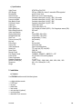
c) Specifications
Video Format
HDD Storage
Record Mode
Search Function
Camera Input Signal
Camera Loop Back
Main Monitor Output
Call Monitor Output
Audio Input
Audio Output
Motion Detect Area
Motion Detect Sensitivity
Video Loss Detection
Display Refresh Rate
Record Refresh Rate
Dwell Time
Picture-in-picture (PIP)
Key Lock
Picture Zoom
Camera Title
Video Adjustments
Alarm Input
Alarm Output
Remote Control
Time Display Format
Power Source
Power Consumption
Operating Temperature
RS232C / RS485 (bps)
Dimensions
Weight
NTSC/EIA or PAL/CCIR
IDE type, UDMA 66 or above, 2 removable HDDs supported
manual / alarm / timer
Date & time / event / alarm searching
Composite video signal 1Vp-p/75Ω BNC, 16 channels
Composite video signal 1Vp-p/75Ω BNC, 16 channels
Composite video signal 1Vp-p/75Ω BNC
Composite video signal 1Vp-p/75Ω BNC
4 RCA audio inputs
1 RCA audio output (L/R)
15x12 targets per camera (NTSC) / 15x14 targets per camera (PAL)
256 levels
yes
72ips (NTSC), 60ips (PAL)
15ips (NTSC), 12ips (PAL)
programmable (1~10 sec)
yes (movable)
yes
2x2 (movable)
6 characters max.
Colour/contrast/brightness
TTL input, high (5V), low (GND)
COM, NO
RS232 or RS485
YY/MM/DD ; DD/MM/YY ; MM/DD/YY ; OFF
AC 100-240V ±10% switching adapter
< 45W
10 – 40°C
115200 ; 57600 ; 19200 ; 9600 ; 4800 ; 3600 ; 2400 ; 1200
432 x 110 x 325mm (W x H x D)
5.7kg
2. Installation
a) Contents
Your DVR16M should come with the following items:
•
•
•
•
•
•
•
•
a digital multiplex recorder
2 HDD trays
tray keys
power cable
user manual
rack mounting kit (optional)
mounting screws
demounted 15-pin connector
DVR16M
2
GB
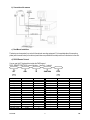
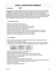
b) Connection with cameras
c) Rack Mount Installation
The device can be mounted in a rack with the optional mounting equipment. Fix the smallest side of the mounting
plates (with the small holes) to the device (screw holes are provided at the sides) and then fix the device to the rack.
d) RS232 Remote Protocol
You can use the PC keyboard to simulate the DMR keypad.
DATA: REMOTE PROTOCOL using 8-bit data – 1 start bit – 1 stop bit
FUNCTION
KEY_MENU
KEY_SELECT
KEY_ENTER
KEY_4CUT
KEY_ZOOM
KEY_9CUT
KEY_PIP
KEY_16CUT
KEY_SLOW
KEY_REC
KEY_LEFT
KEY_UP
KEY_PLAY
KEY_DOWN
KEY_RIGHT
KEY_POWER
KEY_KEY_LOCK
DVR16M
CODE
0 x 4D
0 x 73
0 x 0D
0 x 61
0 x 5A
0 x 62
0 x 70
0 x 63
0 x 53
0 x 72
0 x 4C
0 x 55
0 x 50
0 x 4E
0 x 52
0 x 57
0 x 4B
ASCII
M
S
ENTER
a
Z
b
p
c
S
r
L
U
P
N
R
W
K
FUNCTION
KEY_CH1
KEY_CH2
KEY_CH3
KEY_CH4
KEY_CH5
KEY_CH6
KEY_CH7
KEY_CH8
KEY_CH9
KEY_CH10
KEY_CH11
KEY_CH12
KEY_CH13
KEY_CH14
KEY_CH15
KEY_CH16
3
CODE
0 x 31
0 x 32
0 x 33
0 x 34
0 x 35
0 x 36
0 x 37
0 x 38
0 x 39
0 x 41
0 x 42
0 x 43
0 x 44
0 x 45
0 x 46
0 x 47
ASCII
1
2
3
4
5
6
7
8
9
A
B
C
D
E
F
G
GB
3. Configuration
a) Installing HDD
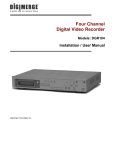
1) HDD Description
1. Handle of the HDD tray
2. Tray lock:
In position A (cf. drawing on the right), the tray is locked and cannot be removed.
In position B, the tray is unlocked and can be removed.
The key lock must be in position A before you switch on the device,
if not the hard disk drive cannot be used in a regular way.
3. Power indicator (green LED): lights up when the device is switched on.
4. HDD access indicator (yellow LED).
2) Installing the Hard Drive into the Tray
•
•
•
•
•
•
•
•
Open the plastic HDD compartment door.
Unlock the tray lock of the desired tray, pull out the handle and pull the tray out of the device.
Push the release latch at the left ("OPEN") to slide the top cover backwards and remove it.
Connect the DC power cable and IDE cable to the HDD.
Insert the HDD in the tray and secure the HDD through the screw holes in the sides.
Put the top cover back on the tray and slide it forward to secure it.
Slide the tray back into the device and lock the tray lock.
Close the plastic HDD compartment door.
When using 2 HDDs at the same time, make sure to set one as 'master' and the other as 'slave' by means of the
jumper on the HDDs themselves.
This device does not support hot swap. Power down the unit and leave it off for more than 60 seconds before
opening it to replace a HDD.
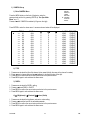
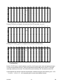
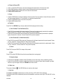
3) Max. Recording Time
The recording time depends on the recording speed and quality. Please refer to the tables below:
Note: these data are the results of a test during which regular TV programs were recorded
NTSC SYSTEM
IPS
rec.
quality
Best
High
Normal
Basic
HDD type
DVR16M
15A
48hr
60hr
96hr
160hr
15
96hr
120hr
192hr
320hr
8
180hr
226hr
360hr
600hr
4
4
360hr
450hr
720hr
1200hr
240GB
2
720hr
900hr
1440hr
2400hr
1
1440hr
1800hr
2880hr
4800hr
GB
PAL SYSTEM
IPS
rec.
quality
Best
High
Normal
Basic
HDD type
12A
48hr
60hr
98hr
162hr
12
100hr
126hr
202hr
336hr
6
202hr
254hr
406hr
676hr
3
406hr
506hr
810hr
1350hr
240GB
2
608hr
760hr
1216hr
2026hr
1
1216hr
1520hr
2440hr
4050hr
b) Control Panel Description
1. HDD trays:
2. Select keys:
3. MENU:
4. ENTER:
5. ZOOM:
6. :
7. SLOW:
8. SELECT:
9. :
10. :
11. :
12. LEDs:
behind the plastic door are the 2 HDD trays. Unlock them and pull them out to insert the HDDs.
press the appropriate camera select key to select the corresponding camera.
Press MENU and enter the password (default: 0000) to access the main menu.
Press ENTER to confirm data or a selection.
Press ZOOM to enlarge the picture displayed on the main monitor.
Press this key to display a picture-in-picture screen.
Press SLOW to slow down the play speed.
Press SELECT and one of the channel select keys to display that channel full screen.
Press this key to go to 4 channel display mode.
Press this key to switch to 7, 9, 10 or 13 channel display mode.
Press this key to go to 16 channel display mode.
HDD: HDD is activated
HDD FULL: HDD is full
ALARM: alarm is armed (when alarm is triggered, LED is flashing)
TIMER: the device is programmed to record
PLAY: recorded material is being reproduced
REC: the device is recording
13. REC:
Press this button to start recording.
14. Controls for video playback
: PLAY: to play recorded video.
!/Down: to stop playback or recording. In setup mode it works as a down button.
"/Up: to pause the fragment. In setup mode it works as an up button.
#/Left: to rewind in PLAY and PAUSE mode. Speed can be adjusted by pressing the REW button
several times. In setup mode it works as a left button.
$/Right: to wind forward in PLAY and PAUSE mode. Speed can be adjusted by pressing the FW
button several times. In setup mode it works as a right button.
15. POWER:
Press this button to power on, and press again to power off.
DVR16M
5
GB
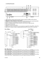
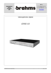
c) Back Panel Description
1. LOOP connectors: bring the channel input signal out again to connect to an additional VCR, monitor etc.
2. VIDEO IN: to connect a video source such as a camera.
3. 75/HI switches: set these switches to the right position for the destination device when using the loop function.
4. POWER: connect the provided adapter to this connector and plug it into the mains.
5. External I/O: the device can be controlled remotely by an external device or trigger mechanism.
6. CALL: to connect a call monitor.
7. MONITOR: to connect the main monitor.
8. AUDIO IN: to connect an audio source such as a microphone (only when IPS is 15A for NTSC or 12A for PAL).
9. AUDIO OUT: to connect to a monitor or speaker system (only when IPS is 15A for NTSC or 12A for PAL).
25-pin COM port
9-pin COM port
PIN 1: GND: GROUND
PIN 2: ALARM INPUT 8: By connecting ALARM INPUT 8 (pin 2) to GND (pin 1), the DVR16M will start recording
and the buzzer will be on. Triggering depends on the set level (high/low) under Menu/Camera/Alarm.
PIN 3: ALARM INPUT 6: By connecting ALARM INPUT 6 (pin 3) to GND (pin 1), the DVR16M will start recording
and the buzzer will be on. Triggering depends on the set level (high/low) under Menu/Camera/Alarm.
PIN 4: ALARM INPUT 4: By connecting ALARM INPUT 4 (pin 4) to GND (pin 1), the DVR16M will start recording
and the buzzer will be on. Triggering depends on the set level (high/low) under Menu/Camera/Alarm.
DVR16M
6
GB
PIN 5: ALARM INPUT 2: By connecting ALARM INPUT 2 (pin 5) to GND (pin 1), the DVR16M will start recording
and the buzzer will be on. Triggering depends on the set level (high/low) under Menu/Camera/Alarm.
PIN 6: ALARM INPUT 16: By connecting ALARM INPUT 16 (pin 6) to GND (pin 1), the DVR16M will start recording
and the buzzer will be on. Triggering depends on the set level (high/low) under Menu/Camera/Alarm.
PIN 7: ALARM INPUT 14: By connecting ALARM INPUT 14 (pin 7) to GND (pin 1), the DVR16M will start recording
and the buzzer will be on. Triggering depends on the set level (high/low) under Menu/Camera/Alarm.
PIN 8: ALARM INPUT 12: By connecting ALARM INPUT 12 (pin 8) to GND (pin 1), the DVR16M will start recording
and the buzzer will be on. Triggering depends on the set level (high/low) under Menu/Camera/Alarm.
PIN 9: ALARM INPUT 10: By connecting ALARM INPUT 10 (pin 9) to GND (pin 1), the DVR16M will start recording
and the buzzer will be on. Triggering depends on the set level (high/low) under Menu/Camera/Alarm.
PIN 10: PIN OFF
PIN 11: RS232-TX + PIN 23: RS232-RX: This device can be controlled remotely by an external device or control
system, such as a control keyboard, using RS-232 serial communications signals.
PIN 12: RS485-A + PIN 24: RS485-B: This device can be controlled remotely by an external device or control
system, such as a control keyboard, using RS-485 serial communications signals.
PIN 13: EXTERNAL ALARM NO + PIN 25: EXT. ALARM COM: During normal functioning COM is connected with
NC and not with NO. When there is an alarm trigger, COM disconnects from NC and connects with NO.
PIN 14: PIN OFF
PIN 15: ALARM INPUT 7: By connecting ALARM INPUT 7 (pin 15) to GND (pin 1), the DVR16M will start recording
and the buzzer will be on. Triggering depends on the set level (high/low) under Menu/Camera/Alarm.
PIN 16: ALARM INPUT 5: By connecting ALARM INPUT 5 (pin 16) to GND (pin 1), the DVR16M will start recording
and the buzzer will be on. Triggering depends on the set level (high/low) under Menu/Camera/Alarm.
PIN 17: ALARM INPUT 3: By connecting ALARM INPUT 3 (pin 17) to GND (pin 1), the DVR16M will start recording
and the buzzer will be on. Triggering depends on the set level (high/low) under Menu/Camera/Alarm.
PIN 18: ALARM INPUT 1: By connecting ALARM INPUT 1 (pin 18) to GND (pin 1), the DVR16M will start recording
and the buzzer will be on. Triggering depends on the set level (high/low) under Menu/Camera/Alarm.
PIN 19: ALARM INPUT 15: By connecting ALARM INPUT 15 (pin 19) to GND (pin 1), the DVR16M will start
recording and the buzzer will be on. Triggering depends on the set level (high/low) under Menu/Camera/Alarm.
PIN 20: ALARM INPUT 13: By connecting ALARM INPUT 13 (pin 20) to GND (pin 1), the DVR16M will start
recording and the buzzer will be on. Triggering depends on the set level (high/low) under Menu/Camera/Alarm.
PIN 21: ALARM INPUT 11: By connecting ALARM INPUT 11 (pin 21) to GND (pin 1), the DVR16M will start
recording and the buzzer will be on. Triggering depends on the set level (high/low) under Menu/Camera/Alarm.
PIN 22: ALARM INPUT 9: By connecting ALARM INPUT 9 (pin 22) to GND (pin 1), the DVR16M will start recording
and the buzzer will be on. Triggering depends on the set level (high/low) under Menu/Camera/Alarm.
4. System Set-up
a) Open Main Menu
Press the MENU button on the front of the device. The screen
you see on the right will be displayed. You will need to enter a
password to access the main menu. Press #or$ (left/right) to
change digits and"or!(up/down) to change the value of the
digit. Press ENTER to confirm the password.
e.g.: password: 0000 (default: 0000)
After entering the correct password and confirming it by pressing
ENTER, this display will appear:
DVR16M
7
PASSWORD: 0000
(MENU)
► SEARCH
TIMER
RECORD
CAMERA
SYSTEM
EVENT
GB
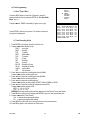
b) System Menu
Press the MENU button on the front of the device, enter the
password and confirm it by pressing ENTER (cf. "4a: Open Main
Menu" on p.7)
(MENU)
SEARCH
TIMER
RECORD
CAMERA
► SYSTEM
EVENT
Press"or!until 'SYSTEM' is selected (cf. figure on the right).
(System)
► AUDIO INPUT: 1
INT AUDIBLE ALARM: ON
EXT AUDIBLE ALARM: ON
ALARM DURATION: 10 SEC
DWELL TIME: 02 SEC
MESSAGE LATCH: NO
TITLE DISPLAY: ON
TIME DISPLAY: Y/M/D
2003-MAY-21 (WED) 22:38:29
NEW PASSWORD: xxxx
CLEAR HDD: MASTER
SYSTEM RESET: NO
REMOTE MODE: RS-232
BAUD RATE: 9600
REMOTE ID: 000
Press ENTER to enter the system set-up menu.
A screen as shown on the right will be displayed.
All instructions below start from this point.
1)
1.
2.
3.
4.
Press"or!to choose 'AUDIO INPUT' and the ENTER button to open the audio input menu.
Press"or!to set the audio input channel 1~4.
Press MENU to confirm the current set-up and return to the previous menu.
Press MENU again to exit and close the system set-up menu.
2)
1.
2.
3.
4.
EXT AUDIBLE ALARM Set-Up
Press"or!to choose EXT AUDIBLE ALARM and the ENTER button to open the menu.
Press"or!to choose EXT AUDIBLE ALARM: ON/OFF (external buzzer on/off)
Press MENU to confirm the current set-up and return to the previous menu.
Press MENU again to exit and close the system set-up menu.
4)
1.
2.
3.
4.
INT AUDIBLE ALARM Set-Up
Press"or!to choose INT AUDIBLE ALARM and the ENTER button to open the menu.
Press"or!to choose INT AUDIBLE ALARM: ON/OFF (internal buzzer on/off)
Press MENU to confirm the current set-up and return to the previous menu.
Press MENU again to exit and close the system set-up menu.
3)
1.
2.
3.
4.
AUDIO INPUT Set-Up
ALARM DURATION Set-Up
Press"or!to choose ALARM DURATION and the ENTER button to open the menu.
Press"or!to choose ALARM DURATION: 10/15/20/30 SEC / 1/2/3/5/10/15/30 MIN / ALWAYS.
Press MENU to confirm the current set-up and return to the previous menu.
Press MENU again to exit and close the system set-up menu.
DVR16M
8
GB
5)
1.
2.
3.
4.
DWELL TIME Set-Up
Press"or!to choose DWELL TIME and the ENTER button to open the menu.
Press"or!to set the dwell time (period each channel is sequentially shown on the monitor): 01~10 SEC.
Press MENU to confirm the current set-up and return to the previous menu.
Press MENU again to exit and close the system set-up menu.
6)
MESSAGE LATCH Set-Up
The user can decide whether or not the External Alarm and Video Loss graphs should appear on the monitor.
1. Press"or!to choose MESSAGE LATCH and the ENTER button to open the menu.
2. Press"or!to set MESSAGE LATCH: ON/OFF.
3. Press MENU to confirm the current set-up and return to the previous menu.
4. Press MENU again to exit and close the system set-up menu.
7)
1.
2.
3.
4.
Press"or!to choose TITLE DISPLAY and the ENTER button to open the menu.
Press"or!to set TITLE DISPLAY (if the title of a channel should appear on the monitor): ON/OFF.
Press MENU to confirm the current set-up and return to the previous menu.
Press MENU again to exit and close the system set-up menu.
8)
1.
2.
3.
4.
TIME DISPLAY Set-Up
Press"or!to choose TIME DISPLAY and the ENTER button to open the menu.
Select a format with"or!: Y-M-D, M-D-Y, D-M-Y (D=day ; M=month ; Y=year) or OFF (time is not displayed).
Press MENU to confirm the current set-up and return to the previous menu.
Press MENU again to exit and close the system set-up menu.
9)
1.
2.
3.
4.
TITLE DISPLAY Set-Up
TIME Set-Up
Press"or!to choose the date and time indication and the ENTER button to open the menu.
Press"or!to change the value and #or$ to move to the previous or next value.
Press MENU to confirm the current set-up and return to the previous menu.
Press MENU again to exit and close the system set-up menu.
10) Change Password (default password : 0000)
1.
2.
3.
4.
Press"or!to choose 'New password' and the ENTER button to open the password menu.
Press"or!to change the value and #or$ to move to the previous or next value.
Press MENU to confirm the current set-up and return to the previous menu.
Press MENU again to exit and close the system set-up menu.
11) CLEAR HDD Yes / No Set-Up
1. Press"or!to choose CLEAR HDD and the ENTER button.
2. Press"or!to set CLEAR HDD: MASTER or SLAVE.
3. Press ►or ◄ to choose between Yes and No:
Yes: press ►to clear the HDD.
No: press◄ NOT to clear the HDD.
4. Press MENU to confirm the current set-up and return to the previous menu.
5. Press MENU again to exit and close the system set-up menu.
DVR16M
9
All Data in HDD
Will Be Cleared
Are you sure?
(◄: No ►: Yes)
GB
12) SYSTEM RESET Set-Up
1. Press"or!to choose SYSTEM RESET and the ENTER button.
2. Press"or!to choose SYSTEM RESET: YES/NO.
Yes: to reset the system (Time & Password set-up will not be changed).
No: not to reset the system.
3. Press MENU to confirm the current set-up and return to the previous menu.
4. Press MENU again to exit and close the system set-up menu.
13) REMOTE MODE Set-Up
1.
2.
3.
4.
Press"or!to choose REMOTE MODE and the ENTER button to open the menu.
Press"or!to set REMOTE MODE: RS-232 / RS-485.
Press MENU to confirm the current set-up and return to the previous menu.
Press MENU again to exit and close the system set-up menu.
14) Remote Protocol Transmission BAUD RATE Set-Up
1.
2.
3.
4.
Press"or!to choose BAUD RATE and the ENTER button to open the menu.
Press"or!to set BAUD RATE: 115200 / 57600 / 19200 / 9600 / 4800 / 3600 / 2400 / 1200.
Press MENU to confirm the current set-up and return to the previous menu.
Press MENU again to exit and close the system set-up menu.
15) REMOTE ID Set-Up (only when RS-232 is selected as remote protocol)
The RS232 protocol allows you to operate several DVR16M. The identification number can vary from 000 to 255.
1. Press"or!to choose REMOTE ID and the ENTER button to open the menu.
2. Press"or!to set REMOTE ID: 000~255.
3. Press MENU to confirm the current set-up and return to the previous menu.
4. Press MENU again to exit and close the system set-up menu.
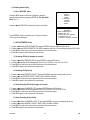
c) Search Menu
Press the MENU button on the front of the device, enter the
password and confirm it by pressing ENTER (cf. "4a: Open Main
Menu" on p.7)
Press"or!until 'SEARCH' is selected (cf. figure on the right).
Press ENTER to enter the search set-up menu.
A screen as shown on the right will be displayed.
From here on, follow the steps as indicated below.
DVR16M
(MENU)
► SEARCH
TIMER
RECORD
CAMERA
SYSTEM
EVENT
► LAST RECORD
FULL LIST
ALARM LIST
TIME SEARCH
10
GB
1) Last Recording
Press "or!to select 'LAST RECORD' and press ENTER to
play the last recording.
2) Full list of recordings
Press "or!to select 'FULL LIST'. Press ENTER to obtain the
full list and a screen as shown on the right will be displayed.
Press #or$ to switch pages (8 events per page) and select the
desired recording with"or!.
Press ENTER to play the selected recording.
M = Manual Recording
A = Alarm Recording
T = Timer Recording
M-HDD = storage in master HDD
S-HDD = storage in slave HDD
3) Recorded Video in Alarm List
Press "or!to select 'Alarm List'. Press ENTER to obtain the
alarm list and a screen as shown on the right will be displayed.
Press #or$ to switch pages (8 events per page) and select the
desired recording with"or!.
Press ENTER to play the selected recording.
► M 2002-JAN-01 01:02:03 M-HDD
M 2002-JAN-01 01:02:03 M-HDD
A 2002-JAN-01 01:02:03 M-HDD
T 2002-JAN-01 01:02:03 M-HDD
T 2002-JAN-01 01:02:03 S-HDD
M 2002-JAN-01 01:02:03 S-HDD
A 2002-JAN-01 01:02:03 S-HDD
T 2002-JAN-01 01:02:03 S-HDD
◄: Page Up ►: Page Down
► A 2002-JAN-01 01:02:03 M-HDD
A 2002-JAN-01 01:02:03 M-HDD
A 2002-JAN-01 01:02:03 M-HDD
A 2002-JAN-01 01:02:03 M-HDD
A 2002-JAN-01 01:02:03 M-HDD
A 2002-JAN-01 01:02:03 M-HDD
A 2002-JAN-01 01:02:03 S-HDD
A 2002-JAN-01 01:02:03 S-HDD
◄: Page Up ►: Page Down
4) Search a recording by time
Press "or!to select 'Time Search'. Press ENTER to obtain the
search screen and a screen as shown on the right will be
displayed.
Press #or$ to switch parameters and"or!to change the
parameter value.
Press ENTER to play the selected recording. If there is no
recording available for the time provided, the screen will display
"Not Found".
DVR16M
11
Play Time: 2002-JAN-01 18
GB
d) Timer Programming
1) Enter "Timer" Menu
Press the MENU button on the front of the device, enter the
password and confirm it by pressing ENTER (cf. "4a: Open Main
Menu" on p. 7)
Press"or!until 'TIMER' is selected (cf. figure on the right).
Press ENTER to enter the timer menu. The screen as shown on
the right will be displayed.
(Menu)
SEARCH
► TIMER
RECORD
CAMERA
SYSTEM
EVENT
(TIMER)
DAY
START END QUALITY IPS
DAILY 00:00 00:00 BEST 15A
DAILY 00:00 00:00 BEST 15A
DAILY 00:00 00:00 BEST 15A
DAILY 00:00 00:00 BEST 15A
DAILY 00:00 00:00 BEST 15A
DAILY 00:00 00:00 BEST 15A
DAILY 00:00 00:00 BEST 15A
TIMER ENABLE: NO
2) Timer Recording Set-Up
1. Press ENTER to set the day selection of the first line.
2. Press"or!to select the day set-up:
DAILY : every day
MON
: Monday
TUE
: Tuesday
WED
: Wednesday
THU
: Thursday
FRI
: Friday
SAT
: Saturday
SUN
: Sunday
MO-FR : Monday to Friday
SA-SU : Saturday & Sunday
JAN-01 : special date.
OFF
: Not activated
3. Press #or$ to select the recording start time (HH:MM).
Press"or!to set the recording start time.
4. Press #or$ to select the recording end time (HH:MM).
Press"or!to set the recording end time.
5. Press #or$ to select the recording quality.
Press"or!to set the recording quality to BEST, HIGH, NORMAL or BASIC.
6. Press #or$ to select the number of images per second (IPS).
Press"or!to set the number of IPS:
NTSC : 1, 2, 4, 8, 15, 15A
PAL: 1, 2, 3, 6, 12, 12A
REMARK: Recording quality and format are determined in the 'Record' menu (see below).
7. Press MENU to confirm current settings and ENTER to go to the next programming line.
8. Press"or!to select 'Timer Enable'
Yes: to activate the programmed settings.
No: to ignore the programmed settings.
9. Press MENU to confirm the current set-up and return to the previous menu.
10. Press MENU again to exit and close the Timer menu.
DVR16M
12
GB
e) Recording Mode Set-Up
1) Enter "RECORD" menu
Press the MENU button on the front of the device, enter the
password and confirm it by pressing ENTER (cf. "4a: Open Main
Menu" on p. 7)
(MENU)
SEARCH
TIMER
► RECORD
CAMERA
SYSTEM
EVENT
Press"or!until 'RECORD' is selected (cf. figure on the right).
Press ENTER to enter the recording menu. A screen as shown
on the right will be displayed.
(RECORD)
► HDD OVERWRITE: NO
RECORD IPS: 15A
RECORD QUALITY: NORMAL
ALARM REC IPS: 15A
ALARM REC QUALITY: NORMAL
2) HDD OVERWRITE Set-Up
1.
2.
3.
4.
Press"or!to select 'HDD OVERWRITE' and press ENTER to open the HDD overwrite set-up.
Press"or!to set HDD OVERWRITE: YES (HDD overwritten when full) / NO (recording stops when HDD is full)
Press MENU to confirm the current set-up and return to the previous menu.
Press MENU again to exit and close the record menu.
3) Recording IPS Set-Up (images per second)
1.
2.
3.
4.
Press"or!to select 'RECORD IPS' and press ENTER to open the IPS set-up.
Press"or!to set the IPS recording speed: 15A-15-8-4-2-1 (NTSC) or 12A-12-6-3-2-1 (PAL).
Press MENU to confirm the current set-up and return to the previous menu.
Press MENU again to exit and close the record menu.
4) Recording Quality Set-Up
1.
2.
3.
4.
Press"or!to select 'RECORD QUALITY' and press ENTER to open the recording quality set-up.
Press"or!to set RECORD QUALITY: BEST, HIGH, NORMAL or BASIC.
Press MENU to confirm the current set-up and return to the previous menu.
Press MENU again to exit and close the record menu.
5) Alarm Recording IPS Set-Up (images per second)
1.
2.
3.
4.
Press"or!to select 'ALARM REC IPS' and press ENTER to open the IPS set-up.
Press"or!to set the IPS recording speed: 15A-8-4-2-1 (NTSC) or 12A-12-6-3-2-1 (PAL).
Press MENU to confirm the current set-up and return to the previous menu.
Press MENU again to exit and close the record menu.
6) Alarm Recording Quality Set-Up
1.
2.
3.
4.
Press"or!to select 'ALARM REC QUALITY' and press ENTER to open the recording quality set-up.
Press"or!to set ALARM REC QUALITY: BEST, HIGH, NORMAL or BASIC.
Press MENU to confirm the current set-up and return to the previous menu.
Press MENU again to exit and close the record menu.
DVR16M
13
GB
f) CAMERA Set-up
1) Enter CAMERA Menu
(MENU)
SEARCH
TIMER
RECORD
► CAMERA
SYSTEM
EVENT
Press the MENU button on the front of the device, enter the
password and confirm it by pressing ENTER (cf. "4a: Open Main
Menu" on p. 7)
Press"or!until 'CAMERA' is selected (cf. figure on the right).
Press ENTER to enter the alarm menu. A screen as shown below will be displayed.
►
TITLE
---- 01
---- 02
---- 03
---- 04
---- 05
---- 06
---- 07
---- 08
---- 09
---- 10
---- 11
---- 12
---- 13
---- 14
---- 15
---- 16
DWELL
ON
ON
ON
ON
ON
ON
ON
ON
ON
ON
ON
ON
ON
ON
ON
ON
5
5
5
5
5
5
5
5
5
5
5
5
5
5
5
5
5
5
5
5
5
5
5
5
5
5
5
5
5
5
5
5
5
5
5
5
5
5
5
5
5
5
5
5
5
5
5
5
ALARM RECORD
LOW
EVENT
LOW
EVENT
LOW
EVENT
LOW
EVENT
LOW
EVENT
LOW
EVENT
LOW
EVENT
LOW
EVENT
LOW
EVENT
LOW
EVENT
LOW
EVENT
LOW
EVENT
LOW
EVENT
LOW
EVENT
LOW
EVENT
LOW
EVENT
2) TITLE
1.
2.
3.
4.
Press#or$ to select the title of the channel to be named (initially the name is the channel's number).
Press #or$ to change digits and"or!(up/down) to change the value of the digit.
Press MENU to confirm the current set-up and return to the previous menu.
Press MENU again to exit and close the alarm menu.
3) DWELL
1.
2.
3.
4.
Press#or$ to select the DWELL setting.
Press"or!to set DWELL: ON/OFF.
Press MENU to confirm the current set-up and return to the previous menu.
Press MENU again to exit and close the alarm menu.
4)
1.
2.
3.
4.
(Brightness) /
(Contrast) /
(colour) Set-Up
Press#or$ to select the brightness, contrast or colour setting.
Press"or!to set the level for the selected parameter.
Press MENU to confirm the current set-up and return to the previous menu.
Press MENU again to exit and close the alarm menu.
DVR16M
14
GB
5) Alarm Polarity Set-Up
1.
2.
3.
4.
Press#or$ to select the alarm polarity setting.
Press"or!to set the alarm polarity LOW / OFF / HIGH.
Press MENU to confirm the current set-up and return to the previous menu.
Press MENU again to exit and close the alarm menu.
6) Alarm Recording Mode Set-Up
1. Press#or$ to select the RECORD setting.
2. Press"or!to choose the recording mode: EVENT / NORMAL / OFF.
EVENT: when the alarm on this channel is triggered, it will be recorded more frequently than other channels.
NORMAL: alarm triggering will not affect the recording frequency of this channel.
OFF: this channel will not be recorded under any circumstances.
3. Press MENU to confirm the current set-up and return to the previous menu.
4. Press MENU again to exit and close the alarm menu.
g) Motion Detection Set-Up
1) Enter Motion Detection Menu
(MENU)
SEARCH
TIMER
RECORD
► CAMERA
SYSTEM
EVENT
Press the MENU button on the front of the device, enter the password
and confirm it by pressing ENTER (cf. "4a: Open Main Menu" on p. 7).
Press"or!until 'CAMERA' is selected (cf. figure on the right).
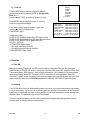
Press ENTER TWICE to enter the motion detection menu. The current camera picture is shown, overlaid with the
motion targets (see below). Push the up, down, left & right buttons to move around in the grid.
REMARK: a motion detection will not automatically trigger the live or recording mode. It will only affect the sequence
of channels shown in live/recording mode, with the icon appearing when a motion detected channel is shown.
1
2
3
4
5
6
7
8
9
10
11
12
13
14
15
032
--
--
--
--
--
--
--
--
--
--
--
--
--
--
--
2) Set Detection Area
Pressing the ENTER button will activate / deactivate the selected position (see figure below: row 6, column 7).
Alternately, you can push the channel select button of the cell on the row you're on that you would like to turn on/off.
DVR16M
15
GB
1
2
3
4
5
6
7
8
9
10
11
12
13
14
15
032
--
--
--
--
--
--
--
--
--
--
--
--
--
--
--
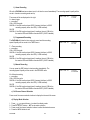
Pressing 'ZOOM' will turn all targets in the current row ON of OFF (see below - ex: row 6)
1
2
3
4
5
6
7
8
9
10
11
12
13
14
15
032
--
--
--
--
--
--
--
--
--
--
--
--
--
--
--
Pressing the PIP button ( ) will turn all targets on the screen ON or OFF (see below).
1
2
3
4
5
6
7
8
9
10
11
12
13
14
15
032
--
--
--
--
--
--
--
--
--
--
--
--
--
--
--
3) Set Sensitivity
Press the "SLOW" button to adjust the detection sensitivity, which focuses on both motion and brightness changes.
The value is shown between columns 7 and 8 (see figures above) and the default value is set at 32. A low value
means high sensitivity and vice versa. The minimum value (max. sensitivity) is 001; the maximum value is 255.
A motion detection will make the concerned channels appear in between the regular channel switching, like: 1-x-2-x3-x-4-x-5-x-…-x-16-x-1x--2-…, with x representing one (or more) motion detected channels.
DVR16M
16
GB
h)
Event List
Press the MENU button on the front of the device, enter the
password and confirm it by pressing ENTER (cf. "4a: Open Main
Menu" on p. 7)
Press"or!until 'EVENT' is selected (cf. figure on the right).
Press ENTER to see the entire 'list of events'. A screen as
shown on the right will be displayed.
Press #or$ to switch pages (8 events on 1 page) and
press"or!to select the desired event.
Press ENTER to play it.
Possible event codes:
M-HDD / S-HDD WARNING: Master/Slave HDD might be failed.
M-HDD / S-HDD LOSS: Master/Slave HDD does not exist/not found.
M-HDD / S-HDD ERROR: Error on Master/Slave HDD
HDD FULL: HDD is full
SYSTEM ERROR: System failure
----02 VLOSS: Video loss on channel 2
----03 ALARM: External I/O alarm on channel 3
POWER RESTORE: Power restore.
(MENU)
SEARCH
TIMER
RECORD
CAMERA
SYSTEM
► EVENT
M-HDD WARNING 2002-JAN-01 03:00:00
M-HDD LOSS
2002-JAN-01 03:00:00
M-HDD ERROR
2002-JAN-01 03:00:00
S-HDD WARNING 2002-JAN-01 03:00:00
HDD FULL
2002-JAN-01 03:00:00
SYSTEM ERROR 2002-JAN-01 03:00:00
----02 VLOSS
2002-JAN-01 03:00:00
----03 ALARM
2002-JAN-02 03:00:00
◄: Page Up ►: Page Down ◄+►: CLEAR
5. Operation
a) Power ON
Before turning power ON make sure any HDD has been locked, and the power LED is red. After pressing the
POWER button, the POWER LED will turn to orange and all the other LEDs will turn RED, except the LED for HDD.
The screen will display "HDD Detecting" ; power on period will be approx. 5 to 15 seconds. If HDD is set as master,
the screen will display " Master HDD Connected". If HDD is set as slave, the screen will display " Slave HDD
Connected". In order to shorten the power on running time, we suggest setting the HDD as master (by means of the
jumper on the HDD itself). When the DVR16M has powered on completely, the POWER LED will turn to green.
b) Recording
Your DVR16M offers a variety of flexible recording modes. You can set it up to record continuously or programmed,
or only to record events ; you can even set the recording speed and resolution. All these options are set through the
system menu. If there should be a power cut during recording, the device will automatically resume recording when
the power returns. The original recording set-up will be respected.
There are 3 recording modes for your device: alarm recording mode, programmed recording mode and manual
recording mode. All recording modes are described here:
DVR16M
17
GB
1) Alarm Recording
When the DVR16M receives an alarm input, it will start to record immediately. The recording speed & quality will be
as set in the alarm recording mode set-up.
The screen will be as displayed on the right.
A = alarm trigger
● = recording
OW = HDD overwrite
032GB = if the OW location shows 32GB, it means that there is 32GB
recording capacity left on the HDD (1 HDD installed).
001GB
032GB = if the OW location shows these 2 readings, there is 1GB left on
the master HDD and 32MB on the slave HDD (2 HDD installed).
2002 - JAN - 01
01:02:03
A ● OW
2002 - JAN - 01
01:02:03
T ● OW
2002 - JAN - 01
01:02:03
M ● 001GB
2) Programmed Recording
The DVR16M will follow the timer set-up to record and the recording
speed & quality will be as set in the TIMER menu.
T = Timer recording
● = recording
OW = HDD overwrite
032GB = if the OW location shows 32GB, it means that there is 32GB
recording capacity left on the HDD (1 HDD installed).
001GB
032GB = if the OW location shows these 2 readings, there is 1GB left on
the master HDD and 32MB on the slave HDD (2 HDD installed).
3) Manual Recording
You can press the REC button to start recording immediately. The
recording speed & quality will be as set in the RECORD menu.
M = Manual recording
● = recording
OW = HDD over write
032GB = if the OW location shows 32GB, it means that there is 32GB
recording capacity left on the HDD (1 HDD installed).
001GB
032GB = if the OW location shows these 2 readings, there is 1GB left on
the master HDD and 32MB on the slave HDD (2 HDD installed).
c) Full Screen Channel Selection
Press one of the camera selection buttons to display that channel full screen.
d) Display Mode Selection
1.
2.
3.
4.
Press , or several times to select the display mode.
Press the SELECT button + #or $ to select a position.
Press one of the channel selection buttons to select the desired camera.
Press the MENU button to exit.
DVR16M
18
GB
e) Picture-in-Picture (PIP)
1.
2.
3.
4.
Press to select the PIP screen: a full screen 'background' channel with a 1/16 size screen insert.
Press one of the channel selection buttons to select the desired channel for the insert screen.
Press the SELECT button and then #or $ to move the insert screen.
Press the MENU button to exit.
f) Zoom
1. Press the ZOOM button to enlarge the display of the main picture. The zoom picture is shown full screen, and the
full channel image appears in a ¼ size format in an inserted moveable window.
2. Press the ZOOM button again to move the zoom pointer.
3. Press the MENU button to exit.
g) Playback
Press PLAY: the DVR16M will go into play mode and will start playing the last recording.
1) Fast Forward (F.F.) & Fast Rewind (F.R.)
• Press PLAY then press$for fast forward searching. Press once for double speed, press twice for quadruple
speed, 3 times for 8x, 4 times for 16x and 5 times for 32x (maximum speed).
• Press PLAY then press #for fast rewind searching. Press once for double speed, press twice for quadruple
speed, 3 times for 8x, 4 times for 16x and 5 times for 32x (maximum speed).
2) Slow Forward (S.F.) & Slow Rewind (S.R.)
• Press PLAY then press SLOW for slow play. Press$once for half speed, press twice for quarter speed, 3 times
for 1/8x, 4 times for 1/16x and 5 times for 1/32x (minimum speed).
• Press PLAY then press SLOW for slow play. Press #once for half speed, press twice for quarter speed, 3 times
for 1/8x, 4 times for 1/16x and 5 times for 1/32x (minimum speed).
3) Pause
Press PLAY then press PAUSE, the image will be paused.
4) Stop
Press STOP and the DVR16M will stop all actions and display the incoming signal.
5) Image by image
• Press PLAY and PAUSE to pause the image. Press$to go to the next image ; keep it pressed to go faster.
• Press PLAY and PAUSE to pause the image. Press #to go to the previous image; keep it pressed to go faster.
When the very first image is shown, the DVR16M cannot return further.
h) Video Loss
The screen will display "
" if the DVR16M does not receive a video signal.
i) Key Lock
Press MENU and ENTER simultaneously to lock the control keys. "KEY LOCK" will be displayed.
Press MENU and ENTER simultaneously and enter the password to unlock the control keys. "KEY UNLOCK" will be
displayed.
DVR16M
19
GB
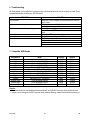
6. Troubleshooting
What may appear to be a malfunction of the device may not be that serious at all and can be easily corrected. Check
the table below before contacting your DVR16M dealer.
PROBLEM
HDD not found
No power
The device does not react to keys being pressed
No recorded video
The device does not start recording
No live video
SOLUTION
Make sure a HDD is inserted and connected and that the HDD
tray is locked.
Check power source cable connections.
Confirm that there is power at the outlet.
Check if it is under key lock mode.
Press MENU and ENTER simultaneously to exit the key lock
mode.
Check if the HDD has been installed properly.
Check if 'record enable' is set to "YES"
Check camera video cable and connections
Check monitor video cable and connections
Confirm that the camera is powered
Check camera lens setting
7. Compatible HDD Brands
Manufacturer
HITACHI
IBM
IBM
IBM
IBM
Maxtor
Maxtor
Seagate
Seagate
Seagate
Western Digital
Western Digital
Western Digital
Model
Deskstar 180GPX (120GB)
Deskstar 120GXP (40GB)
Deskstar 60GXP IC35I060
Deskstar 120GXP (80GB)
Deskstar 120GXP (120GB)
DiamondMax 536DX (60GB) 4W060H4
DiamondMax Plus 9, Model#6Y120L
Barracuda ATA IV ST340016A
Barracuda ATA V, ST3120023A
Barracuda ATA IV, ST380021A
Caviar WD400BB-00BSA0
Caviar WD400EB-00CPF0
Caviar WD1200BB-00CAA1
Capacity
120GB
40GB
60GB
80GB
120GB
60GB
120GB
40GB
120GB
80GB
40GB
40GB
120GB
Rotation
7200rpm
7200rpm
7200rpm
7200rpm
7200rpm
7200rpm
7200rpm
7200rpm
7200rpm
7200rpm
7200rpm
5400rpm
7200rpm
Remarks
• The listed brands have been tested and are compatible with the DVR16M. Do not use other brands than these.
• In order to avoid damage to the HDD, leave the device switched off during at least 60 seconds before removing it.
DVR16M
20
GB