1
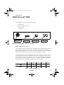
2518 IV.BOOK Page 1 Tuesday, September 22, 1998 7:10 PM
2518 DMX Controller
P/N 510158
use r manu al
2518 IV.BOOK Page 2 Tuesday, September 22, 1998 7:10 PM
© 1997 - 1998 Martin Professional A/S, Denmark.
All rights reserved. No part of this manual may be
reproduced, in any form or by any means, without
permission in writing from Martin Professional A/S,
Denmark.
Printed in Denmark.
P/N 510158 - Version 980828-MA
2518 IV.BOOK Page 3 Tuesday, September 22, 1998 7:10 PM
3
2518 DMX Controller
2518 IV.BOOK Page 1 Tuesday, September 22, 1998 7:10 PM
section 1
Introduction
Safety Precautions ...............................................................................................2
Features ...............................................................................................................2
Accessories ..........................................................................................................2
section 2
Installation
Connecting the Serial Link ....................................................................................3
Connecting a PC ..................................................................................................5
Connecting a MIDI Device ....................................................................................6
Connecting to the Power Supply ..........................................................................6
section 3
Address and Mode Setting
About Addresses and Modes ...............................................................................7
Setting an Address ...............................................................................................8
section 4
Operation
Manual Control ...................................................................................................10
Programming Scenes .........................................................................................11
MIDI Scenes .......................................................................................................13
Executing Scenes ...............................................................................................14
Blackout (Standby) Mode ...................................................................................16
appendix a
Troubleshooting
............................................................................................................................17
appendix b
Service
Calibrating Faders ..............................................................................................18
appendix c
Specifications
............................................................................................................................19
Table of Contents
1
2518 IV.BOOK Page 2 Tuesday, September 22, 1998 7:10 PM
section 1
INTRODUCTION
Thank you for selecting the Martin 2518 DMX Controller. It is a ruggedly built, easy to use
controller that offers 72-channel DMX control and multiple triggering options.
Safety Precautions
•
The 2518 DMX Controller is not for domestic use.
•
Use the device only as described.
•
Do not expose the device to rain or moisture.
•
Make sure the device is properly grounded.
•
Do not operate the device with the cover removed.
•
Immediately repair or replace damaged power cords.
•
There are no user-serviceable parts inside; refer all service to a qualified technician.
Features
•
72 DMX channels
•
30 banks of 6 programmable scenes
•
6 faders for manual control
•
Built-in microphone for music triggering
•
Built-in timer for automatic triggering
•
Interface for MIDI triggering, scene and bank selection
•
2-digit LED display
•
Blackout master
•
Manual override
•
Solid steel construction
•
Table or 19” rack mount
•
Low current standby mode
Accessories
2
•
Martin 4-Channel Opto-Isolated RS-485 Splitter........................................ P/N 920630
•
Martin 6 Channel DMX Switch Pack, 210 - 245 ........................................ P/N 920410
•
Martin 6 Channel DMX Switch Pack, 100 - 130 V..................................... P/N 920412
2518 DMX Controller
2518 IV.BOOK Page 3 Tuesday, September 22, 1998 7:10 PM
section 2
INSTALLATION
The 2518 DMX Controller comes with the following:
•
IEC power cable
•
5 meter 3-pin XLR-XLR cable
•
Termination plug
•
User manual
Rear Panel Connections
DMX Output
RS-232 I/O
MIDI Input
AC Input
Connecting the Serial Link
About Serials Links
The 2518 DMX Controller sends instructions to lighting fixtures and other DMX-controlled
devices through a serial link. A cable connects, or “links,” the output of the controller to the
input of the first lighting fixture. The link is continued to additional fixtures by connecting
the output of the fixture closest to the controller to the input of the next fixture.
Connecting outputs to inputs is complicated a little by the fact that the connection sockets
are not always the same. There are 2 differences to be aware of. First, both 3-pin and 5-pin
XLR sockets are common even though only 3 wires are used for DMX control. Second, the
way the socket pins are wired, known as the pin-out, is different for the Martin standard and
the DMX standard. The pin-outs for each standard are shown in Table 1.
Pin 1
Pin 2
Pin 3
Pin 4
Pin 5
DMX
shield
cold (-)
hot (+)
-
-
Martin
shield
hot (+)
cold (-)
-
-
Table 1: Martin and DMX Pin-Outs
Installation
3
2518 IV.BOOK Page 4 Tuesday, September 22, 1998 7:10 PM
The 2518 DMX Controller uses the DMX pin-out!
The 2518 DMX Controller uses the DMX pin-out. Other Martin products with DMX pinout include the Punisher X250, the Destroyer X250, and the DMX Switch Pack. The pinout for Martin products is always shown next to the connection sockets for the serial link.
Whatever the pin-out, you must connect hot to hot and cold to cold. This means that when
connecting a device with DMX pin-out to a device with Martin pin-out, you must use a
phase-reversing cable that swaps the connections between pins 2 and 3.
Output
Martin
pin 2 (+)
pin 3 (-)
Polarity
3-pin
5-pin
DMX
pin 2 (-)
pin 3 (+)
3-pin
Input
Martin
pin 2 (+)
pin 3 (-)
XLR
DMX
pin 2 (-)
pin 3 (+)
3-pin
3-pin
5-pin
Male Female
1
1
2
2
3
3
Male Female
1
1
2
2
3
3
Male Female
1
1
2
2
3
3
4
5
P/N 309022
P/N 309158
P/N 309162
Male Female
1
1
2
2
3
3
Male Female
1
1
2
2
3
3
Male Female
1
1
2
2
3
3
4
5
P/N 309158
P/N 309022
P/N 309160
Male Female
1
1
2
2
3
3
4
5
Male Female
1
1
2
2
3
3
4
5
Male Female
1
1
2
2
3
3
4
4
5
5
P/N 309163
-
-
Table 2: XLR Cable Requirements
4
2518 DMX Controller
2518 IV.BOOK Page 5 Tuesday, September 22, 1998 7:10 PM
Building the Serial Link
1.
Use shielded twisted-pair cable. Though standard microphone cable may
work, it is less reliable than shielded twisted pair cable. Use 24 AWG cable for
runs up to 300 meters (1000 ft) and use 22 AWG cable for runs up to 500
meters (1640 ft). Your Martin dealer has a range of cables, connectors, and
adaptors designed for lighting control.
2.
Starting from the controller, connect output to input. Check the pinout on Martin fixtures and be sure to connect hot to hot and cold to cold.
Use Table 2 to help plan your cable and connector needs.
3.
Never use a “Y” connector to split the link. It often convenient to split
the serial link into branches. If so, use a dedicated splitter/amplifier such
as the Martin 4-Channel Opto-Isolated RS-485 Splitter.
4.
Don’t overload the link. Up to 32 devices can be connected on a serial
link. Placing more than 32 devices on a link can cause unpredictable performance. The control units for the RoboColor IIx and RoboColor III systems and the Martin DMX Switch Pack each count as 1device.
5.
Always terminate the link. Terminate the link by installing the provided
termination plug in the output socket of the last fixture on the link. The
termination plug, which is simply a male XLR connector with a 120 ohm
resistor soldered between pins 2 and 3, “soaks up” the control signal so it
cannot reflect back down the link. If a splitter is used, terminate each
branch of the link.
Connecting a PC
The 2518 Upload/Download Utility, available for download from the Martin web site at
http://www.martin.dk, is a Windows PC tool for managing lighting programs created with
the 2518 DMX Controller. The program allows the user to:
•
Download the memory of all banks from the 2518 DMX Controller to a PC.
•
Upload a set, or “memory”, of 30 banks from a PC to the controller.
•
Name, save and read individual banks.
•
Reconfigure, save and read memories of 30 banks
•
View and edit the DMX values for all scenes.
•
See the changes as you make them in real time.
To use the 2518 DMX Controller with a computer, a straight-through RS-232 cable must be
connected between the computer’s serial port and the controller’s RS-232 I/O port. Disconnect both devices from AC power before connecting the RS-232 cable.
Installation
5
2518 IV.BOOK Page 6 Tuesday, September 22, 1998 7:10 PM
Connecting a MIDI Device
With a MIDI device connected to the 2518 DMX Controller, you can control lights via
MIDI. Connect the device’s MIDI output to the controller’s MIDI input using a standard
MIDI cable. A standard MIDI cable consists of a shielded twisted-pair and 5-pin DIN connectors wired pin 2 to pin 2, pin 4 to pin 4, and pin 5 to pin 5. The cable shield is connected
to pin 2. Pins 1 and 3 are not used. The cable may be up to 15 meters (50 feet) long.
C o n n e c t i n g t o t h e Pow e r S u p p ly
WA R N I N G !
For safe operation, the controller must be grounded (earthed).
Install Plug
The 2518 DMX Controller is delivered without a plug on the power cord. Following the
manufacturer’s instructions, install an approved 3-prong grounding-type plug that fits your
supply. Connect the wires to the pins as listed below. If the pins are not clearly identified, or
if you have any doubts about proper installation, consult a qualified electrician.
Possible Markings
Wire
Pin
Typical
US
UK
brown
live
“L”
yellow or
brass
red
blue
neutral
“N”
silver
black
yellow/green
ground
(earth)
green
green
Table 3: Plug Wiring
6
2518 DMX Controller
2518 IV.BOOK Page 7 Tuesday, September 22, 1998 7:10 PM
section 3
ADDRESS AND MODE SETTING
About Addresses and Modes
Devices connected to the serial link must have an address, also known as the start channel,
which is the first channel the controller uses to send instructions to the devices. The address
must be unique for each device. If independent control is not required, 2 or more devices
with the same DMX protocol may have the same address; they will receive the same
instructions and behave identically.
Before setting addresses, you must know how many control channels each device requires.
This depends on the number of effects the device has and possible options such as 8 or 16bit pan/tilt resolution and tracking or vector mode. These are described in the device’s user
manual.
If a device can be operated in tracking or vector mode, you should select vector mode. The
2518 DMX Controller does not have a dedicated speed control (fade time) and does not
support tracking mode. In vector mode, speed is programmed on 1 or 2 additional channels.
Devices may be controlled in tracking mode if there are not enough channels, but speed
control will not be possible.
37- 72
1- 36
Controlling a light is easiest if all its channels are assigned to one channel button. This give
the fastest access to the light’s features. The buttons are divided into 12 groups of 6 channels as shown below.
Button 1
Button 2
Button 3
Button 4
Button 5
Ch Setting Ch Setting Ch Setting Ch Setting Ch Setting
Button 6
Ch Setting
4
4
:
4/#5/#6
46
4/#6/#7
4<
4/#5/#8
58
4/#7/#8
64
4/#5/#6/#7/#8
5
5
;
7
47
5/#6/#7
53
6/#8
59
5/#7/#8
65
9
6
4/#5
<
4/#7
48
4/#5/#6/#7
54
4/#6/#8
5:
4/#5/#7/#8
66
4/#9
7
6
43
5/#7
49
8
55
5/#6/#8
5;
6/#7/#8
67
5/#9
8
4/#6
44
4/#5/#7
4:
4/#8
56
4/#5/#6/#8
5<
4/#6/#7/#8
68
4/#5/#9
9
5/#6
45
6/#7
4;
5/#8
57
7/#8
63
5/#6/#7/#8
69
6/#9#
6:
4/#6/#9#
76
4/#5/#7/#9
7<
4/#8/#9
88
4/#5/#6/#8/#9 94
4/#6/#7/#8/#9
9:
4/#5/#:
6;
5/#6/#9
77
6/#7/#9
83
5/#8/#9
89
7/#8/#9
95
5/#6/#7/#8/#9
9;
6/#:
6<
4/#5/#6/#9
78
4/#6/#7/#9
84
4/#5/#8/#9
8:
4/#7/#8/#9
96
4/#5/#6/#7/#8/#9 9<
4/#6/#:
73
7/#9
79
5/#6/#7/#9
85
6/#8/#9
8;
5/#7/#8/#9
97
:
:3
5/#6/#:
74
4/#7/#9
7:
4/#5/#6/#7/#9 86
4/#6/#8/#9
8<
4/#5/#7/#8/#9 98
4/#:
:4
4/#5/#6/#:
75
5/#7/#9
7;
8/#9
5/#6/#8/#9
93
6/#7/#8/#9
5/#:
:5
7/#:
87
99
Table 4: Channel Groups and Settings (DIP-Switch Pins ON)
Address and Mode Setting
7
2518 IV.BOOK Page 8 Tuesday, September 22, 1998 7:10 PM
Setting an Address
Addresses are commonly assigned by setting a DIP-switch on the device. DIP-switch settings are shown in Table 4. The settings apply for Martin products and any other devices
that use base 1 numbering, that is, channel 1 is set with DIP-switch 1 on.
The DIP-switch may also be used to enable special options. The Martin Punisher X250 and
Destroyer X250, for example, must be set with DIP-switch 10 on. Please refer to the user
manuals for specific details on address and mode setting.
Addressing Example
Suppose we have the following equipment.
•
•
•
•
•
•
•
2 sets of 4 RoboColor IIx
4 RoboColor Pro 400s
2 RoboScan 812s
2 Punisher X250s
2 Destroyer X250s
1 RoboZap MSR 1200 (with DMX interface)
1 6-Channel DMX Switch Pack
We could set the equipment as shown in Table 5. There are not enough channels to control
everything independently so 2 RoboColor Pro 400s are together on channels 44 - 48 and 2
more are together on channels 56 - 60. They are set for 5-channel tracking mode because
there is not enough room for 7-channel vector mode - speed control will not be possible.
6 Channel
Switch Pack
RoboZap
MSR 1200
Button 6
Ch Device
31
32
33
34
35
36 not used
67
68
69
70
71
72
Destroyer
X250
Button 5
Ch Device
25
26
27
28
29
30 not used
61
62
63
64
65
66
Destroyer
X250
RoboColor
Pro 400 (2)
RoboScan
812
Button 4
Ch Device
19
20
21
22
23
24
55
56
57
58
59
60
Punisher
X250
Button 3
Ch Device
13
14
15
16
17
18
49
50
51
52
53
54
Punisher
X250
RoboColor
Pro 400 (2)
RoboScan
812
37- 72
Button 2
Ch Device
7
8
9
10
11
12
43
44
45
46
47
48
RoboColor
IIx
RoboColor
IIx
1- 36
Button 1
Ch Device
1
2
3
4
5
6
37
38
39
40
41
42
Table 5: Example (Addresses are shaded)
Note that all fixtures except the RoboScan 812s, which require 7 channels, have all their
control channels on a single button. The second Destroyer is set to channel 31 instead of 30
in order to avoid spitting it between 2 buttons.
8
2518 DMX Controller
2518 IV.BOOK Page 9 Tuesday, September 22, 1998 7:10 PM
If instead we wanted independent control of the RoboColor Pro 400s, another option would
be to control the 2 Destroyers together at the same address and run the 2 Punishers in single-channel mode. The fixtures could be addressed as shown in Table 6.
In this setup, there are enough channels to run 2 of the RoboColor Pro 400s in 7-channel
vector mode. The other 2 Pro 400s are running in 5-channel tracking mode; speed control of
these units will not be possible.
6 Channel
Switch Pack
RoboZap
MSR 1200
Button 6
Ch Device
31
32
33
34
35
36
67
68
69
70
71
72
RoboColor
Pro 400
Button 5
Ch Device
25
26
27
28
29
30
61
62
63
64
65
66
RoboColor
Pro 400
RoboScan
812
Button 4
Ch Device
19
20
21
22
23
24
55
56 Punisher
57 Punisher
58
59
60
RoboColor
Pro 400
Button 3
Ch Device
13
14
15
16
17
18
49
50
51
52
53
54
RoboColor
Pro 400
Destroyer
X250 (2)
RoboScan
812
37- 72
Button 2
Ch Device
7
8
9
10
11
12
43
44
45
46
47
48
RoboColor
IIx
RoboColor
IIx
1- 36
Button 1
Ch Device
1
2
3
4
5
6
37
38
39
40
41
42
Table 6: Another Option (Addresses are shaded)
Address and Mode Setting
9
2518 IV.BOOK Page 10 Tuesday, September 22, 1998 7:10 PM
section 4
OPERATION
The 2518 DMX Controller has 3 modes: manual mode, in which you set lights and program
scenes; execution mode, in which scenes are run; and blackout/standby mode, in which the
lights are blacked out.
Manual Control
Channel Master
DMX Channels
1-6
(37-42)
13-18
(49-54)
19-24
(55-60)
25-30
(61-66)
31-36
(67-72)
Blackout
(Standby)
(37-72)
1
7-12
(43-48)
Scenes
1-36
2
3
4
5
10
9
8
7
6
5
4
3
2
1
6
10
9
8
7
6
5
4
3
2
1
Channel Button
Scene Bank
Store
Auto
Music
Midi
Fader
About DMX Control
Devices are set by activating their DMX channels and sliding the faders.
Channels are activated and deactivated in groups of 6 by pressing the channel buttons. Each
channel button controls the 2 groups of channels listed beside the button. The channel master is used to switch the channel buttons between these 2 groups.
The channel button LEDs indicate which channels are active, that is, under fader control. A
lit LED indicates channels from 1 to 36 are active; a flashing LED indicates channels from
37 to 72 are active. Status is indicated for 36 channels at a time: press the channel master to
see the status of the other channels. In the figure above, channels 1 - 6 are active.
The faders set the DMX values on active channels. They map to the channels from left to
right. The DMX value is 0 when a fader is at the bottom and 255 at the top.
The DMX protocol for a device describes how it responds to DMX values. To make a light
red, for example, you would look in the protocol for the channel that controls color and the
DMX value for red. Then you would slide the corresponding fader to the listed value.
10
2518 DMX Controller
2518 IV.BOOK Page 11 Tuesday, September 22, 1998 7:10 PM
Getting Started
1.
Set up the controller and lights as described in sections 2 and 3.
2.
Slide the faders to 0.
3.
Apply power to the lights. Some fixtures must be turned on before the
controller is turned on in order to automatically detect the control protocol. After a short reset procedure, the lights will be ready to respond to
the controller.
4.
Apply power to the 2518 DMX Controller.
Setting Lights
1.
Activate fader control of channels between 1 and
36: Press a channel button to activate control.
2.
Control the effects: Slide the faders up and
down to control the effects. If there is no light from
the fixture, set all effects to the open position and
turn on the lamp, if applicable, using the fixture’s
DMX protocol as your guide.
3.
You may activate fader control on more than one
button if you want to control several fixtures with
the same protocol. This only works if their start
channels map to the same fader.
4.
5.
Deactivate fader control: Press the button again
to turn off fader control. The LED goes out to indicate manual control is turned off.
Activate fader control of channels between 37
and 72: Press the channel master to switch control between channels 1 - 36 and 37 - 72. Press a
channel button to activate control of the second
group of channels.
1-6
(37-42)
13-18
(49-54)
19-24
(55-60)
1-6
(37-42)
1-36
(37-72)
1-6
(37-42)
Programming Scenes
A light show is made up of scenes. A scene is a complete set of DMX values for each fixture. It contains control instructions for all programmable effects for each device. In addition, a scene may contain speed information. For example, some lights have dimmers that
may be set to fade slowly or snap instantly.
Scenes are programmed by setting the lights as described above and then saving the settings
in memory.
Six scenes can be stored in each bank. The 2518 DMX Controller has 30 banks; up to 180
scenes may be programmed and saved in its memory.
Operation
11
2518 IV.BOOK Page 12 Tuesday, September 22, 1998 7:10 PM
Saving a Scene
1.
Press [Store]. The display flashes.
2.
Select a bank in which to save the scene: If you
want to save the scene in a different bank, press
the up and down arrow buttons to switch banks.
The active bank is displayed as a 2-digit number.
3.
Select the scene to save: Press one of the 6
scene buttons. The active scene is displayed as a
1-digit number. The scene is saved when the display stops flashing.
Store
Scene Bank
1
Editing a Scene
1.
Select the scene to edit.
2.
Make the desired changes.
3.
Save the edited scene as described above.
Copying a Scene
If you want to use the settings from one scene as the starting point for another scene, you
may copy the scene and edit it.
1.
Select the scene to be copied.
2.
Make the desired changes.
3.
Save the new scene as described above.
Deleting a Scene
Deleting a scene is not necessary before saving a new one. It may be useful, though, if you
want a fresh start. Deleting a scene is a matter of creating and saving a scene in which all
DMX values are 0.
12
1.
Deactivate all channels.
2.
Slide all faders to 10.
3.
Activate all channels.
4.
Slide all faders to 0.
5.
Press [Store].
6.
Press the scene button to be deleted.
2518 DMX Controller
2518 IV.BOOK Page 13 Tuesday, September 22, 1998 7:10 PM
Deleting all Scenes
Deleting all scenes is useful if the lighting setup changes or if you want to reprogram all
fixtures.
1.
Disconnect the controller from AC power.
2.
Press and hold [Store] and the up arrow button at
the same time.
3.
Store
Apply power.
MIDI Scenes
A MIDI scene is a scene saved together with a MIDI code so the scene can be executed
directly from a MIDI device such as a keyboard, drum machine, or computer with MIDI
output. The scene executes every time its MIDI code is generated.
Any number of scenes may be MIDI scenes. The MIDI code must be different for each
scene.
MIDI scenes can also be used to switch banks. When a MIDI scene is executed, the active
bank automatically changes to the bank where the scene is stored.
If you have several MIDI devices, MIDI response can be limited to a specific MIDI channel. If no channel is selected, the controller responds to all MIDI channels from 1 to
16.
Creating a MIDI Scene
1.
Select a scene.
2.
Press [Midi]. The display flashes.
3.
(Optional) Select a MIDI channel: Press the up
and down arrow buttons to select a channel
between 1 and 16.
1
Midi
Scene Bank
4.
Generate the MIDI code: On you keyboard or
other MIDI device, play the note or execute the
function to save with the scene.
D e l e t i n g a M I D I S c e n e o r Tr i g g e r
1.
Press [Midi]. The display flashes.
2.
Press [Blackout].
Midi
Blackout
(Standby)
Operation
13
2518 IV.BOOK Page 14 Tuesday, September 22, 1998 7:10 PM
3.
Generate the MIDI code: On you keyboard or
other MIDI device, play the note or execute the
function to delete. The display stops flashing
when the code is deleted. The scene itself is not
deleted.
Deleting all MIDI Functions
1.
Disconnect the controller from AC power.
2.
Press and hold [Midi] and the down arrow button at
the same time.
3.
Apply power.
Midi
Executing Scenes
Tr i g g e r O p t i o n s
Scenes can be run in a sequential loop using 3 different triggers:
•
•
•
Auto Trigger: Scenes are executed at the rate that you set using a built-in timer.
Music Trigger: Scenes are executed to the beat of the music using the built-in microphone.
MIDI Trigger: Scenes are executed every time the MIDI code that you select is generated. Up to 2048 MIDI triggers may be selected.
Each trigger pulse executes the next scene in the active bank, starting at scene 1. After
scene 6, the next trigger pulse executes scene 1 again.
Scenes may also be executed manually in any order by pressing the scene buttons.
Changing Banks
The active bank may be switched at any time by pressing the up or down arrow buttons.
Banks can also be switched by executing a MIDI scene. When you execute a MIDI scene,
the active bank automatically switches to the bank where the scene is stored.
Control Precedence
Fader control overrides programmed control!
When a program is executing, any channel can be overridden by activating fader control
and sliding the fader. The DMX value does not change until the fader is moved. Normal
program execution resumes when fader control is deactivated.
Manual and MIDI scene execution take precedence over automatic scene execution. If the
controller is executing scene 3 in music trigger mode and you press the scene 1 button,
scene 1 will be executed. The next trigger pulse will cause sequential execution to continue
14
2518 DMX Controller
2518 IV.BOOK Page 15 Tuesday, September 22, 1998 7:10 PM
at scene 2.
A u t o Tr i g g e r E x e c u t i o n
1.
Set the trigger rate: Press [Auto] once to start timing, wait for the desired trigger interval, and then
press [Auto] again to stop timing.
2.
The scenes execute sequentially. The timer LED
blinks to indicate scene changes as the controller
steps through the bank.
3.
Exit: Press [Auto] again to exit auto trigger mode.
Auto
Auto
M u s i c Tr i g g e r E x e c u t i o n
1.
Start execution: Press [Music]; the Music Trig LED
lights. The controller runs the scenes to the beat of
the music.
2.
Exit: Press [Music] again.
Music
S e l e c t i n g a M I D I Tr i g g e r
Note: A MIDI code may be used either as a trigger or to execute a MIDI scene, but not both.
1.
Press [Midi]. The display flashes.
2.
Press [Auto].
3.
(Optional) Select a MIDI channel: Press the up
and down arrow buttons to select a channel
between 1 and 16.
4.
Generate the MIDI code: On you keyboard or
other MIDI device, play the note or execute the
function to use as a trigger.
5.
Repeat steps 1 - 4 to select additional MIDI codes as desired. Up to 2048
MIDI codes may be selected.
6.
See “Deleting a MIDI Scene or Trigger” on page 13 to delete a trigger.
Midi
Auto
Scene Bank
M I D I Tr i g g e r E x e c u t i o n
1.
Generate the MIDI code. The scene changes each
time a MIDI trigger is generated.
2.
MIDI triggers remain active until deleted.
Operation
15
2518 IV.BOOK Page 16 Tuesday, September 22, 1998 7:10 PM
Blackout (Standby) Mode
In blackout mode, the 2518 DMX Controller blacks out all
devices by sending the DMX value 0 on all channels. Simply
press [Blackout]. Banks and scenes may be selected but not
run. Press [Blackout] again to resume operation.
In standby mode, there is no DMX output from the controller.
Standby mode uses less current and is recommended whenever
the controller is not being used for more than a few minutes to
reduce wear and tear on the electronic components. Press and
hold [Blackout] until the LED lights to activate standby mode.
Press [Blackout] again to return to normal execution.
Disconnect the 2518 DMX Controller from AC power when not in use.
16
2518 DMX Controller
Blackout
(Standby)
Blackout
(Standby)
Scene Bank
2518 IV.BOOK Page 17 Tuesday, September 22, 1998 7:10 PM
appendix a
TR O U B L E S H O O T I N G
problem
probable cause(s)
suggested remedy
The controller is disconnected from the data link.
Connect controller.
Blackout or standby mode
selected.
Press blackout button.
Bad data link connection.
Check data link connections/
cables and correct accordingly.*
DMX signal polarity reversed.
Swap pins 2 and 3. See section 2.
DMX signal reflection.
Insert termination plug in the
last light on the link.
Incorrect addressing of fixtures.
Check addresses.
Fixtures not on.
Turn on fixtures.
Protocol auto-detection failure.
Switch the fixtures off and
then back on. In general,
power on the controller
before the fixtures.
Fixtures do not execute programming on one or more
channels.
Fader control is overriding
programming.
Turn off fader control.
No light from some or all fixtures.
The scenes do not contain
‘Lamp On’ instructions for fixtures with remote lamp on/off.
Make sure the “Lamp On”
command is saved in at least
one scene.
Uneven or incomplete fader
control.
Faders not calibrated.
Calibrate faders as described
in “Service”.
None of the fixtures respond
to the controller.
Some fixtures do not
respond, respond erratically,
or continuously reset.
* To test the data link with an ohm meter, disconnect the link from the controller and measure the resistance across pins 2 and 3 of the XLR male plug. The reading should be around
120 ohms. Readings from 400 - 20,000 ohms indicate the data link is not terminated. Infinite resistance indicates a bad connection, broken wire, or a defective fixture. Very low
readings indicate a short circuit in the data link or a defective fixture.
Troubleshooting
17
2518 IV.BOOK Page 18 Tuesday, September 22, 1998 7:10 PM
appendix b
SERVICE
Calibrating Faders
If the controller does not output the full range of DMX values, or outputs different values
from the same fader position, the faders can be recalibrated as follows.
18
1.
Disconnect the controller from AC power.
2.
Press Scene buttons 4 and 6 at the same time while applying power to
the controller. The channel LEDs chase upwards.
3.
Slide the 6 faders all the way up to the top.
4.
Press a DMX Channel button.
5.
To verify calibration, slide each fader, one at a time, between 0 and
100%. When a fader is at 0, the display must read 0 (DMX 0). When a
fader is at 10, the display must read FF (DMX 255). Do not leave a fader
on 0 - you will not be able to read the other fader values.
6.
Press a DMX Channel button to complete the process and return to normal operation.
2518 DMX Controller
2518 IV.BOOK Page 19 Tuesday, September 22, 1998 7:10 PM
appendix c
SPECIFICATIONS
Dimensions
•
•
•
•
•
Height ............................................................................. 95 mm (3.7")
Length ...........................................................................483 mm (19.0")
Width ...............................................................................130 mm (5.1")
Weight ............................................................................. 2.8 kg (6.1 lb)
Rack size .......................................................................................... 3U
Po w e r C o n s u m p t i o n
•
.................................................................................................... 2.2 W
AC Vo l t a g e a n d F r e q u e n c y
•
•
EU model ....................................................... 210 to 240 V, 50 to 60 Hz
US model ....................................................... 100 to 130 V, 50 to 60 Hz
Programming Capacity
•
•
Scenes ............................................................................................180
MIDI triggers ..................................................................................2048
DMX Capacity
•
...........................................................................................72 channels
Tr i g g e r S o u r c e s
•
........................................... adjustable timer, MIDI, internal microphone
Re a r Pa ne l C onn e ct io ns
•
•
•
•
Power input ................................................ grounding 3-prong IEC male
DMX output.................................................................3-pin XLR female
MIDI input ................................................................... 5-pin DIN female
RS-232 ................................................................... 9-pin D-SUB female
Materials
•
•
•
Cover, case ................................. steel with electrostatic powder coating
Buttons, knobs ............................................................................ plastic
Feet ............................................................................................ rubber
Specifications
19