1
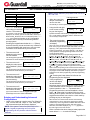
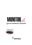
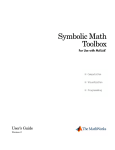
Guardall (formerly VEREX Technology) www.guardall.com | +1 877.249.9993 5201 Explorer Drive, Mississauga, Ont., Canada. L4W-4H1 [email protected] +1 905.206.8434 | [email protected] +1 905.206.8436 | Fax: +1 905.629.4970 21-3691Erev1.3 HSC-IP Module Installation Instructions 9 / 2008 For further information about the HSC-IP Receiver, refer to the HSC-IP Receiver Guide, 21-3690E For further information about IP, refer to the IP Connectivity Guide, 22-9059E Open xL Notices ► ► ► ► ► ► ► ► ► ► ► ► These instructions are used for both the Open xL and Monitor xL versions of xL Security Equipment. A red dot on xL equipment and its packing material will identify it as the Open xL version. Model numbers ending with a “T” will identify the Open xL equipment versions. Open xL and Monitor xL versions of xL Security Equipment can not be used together. VBUS devices can be used with both Open xL and Monitor xL versions of xL Security Equipment. VBUS devices are not used with ISM equipment. Only Monitor xL Security Equipment can be used to upgrade a Monitor ISM security system. The Open xL version is not used with Monitor ISM equipment. Only Monitor xL Director Software can be used to upgrade Director Software that communicates with a Monitor ISM security system. The Open xL Director Software is not used with Monitor ISM equipment. Open xL, Monitor xL and ISM systems can communicate to the same HSC-IP Receiver. However, the Open xL system will require an Open xL HSC-IP Module to communicate with the HSC-IP Receiver. A regular IP Module (non HSC-IP) can be used by an Open xL, Monitor xL or ISM system if they are only communicating to the Monitor xL or Open xL Director Software. Only Monitor xL Director Software can be used with a Monitor xL Security System. Only Open xL Director Software can be used with an Open xL Security System. Confirm that the correct firmware is used when upgrading a security system’s firmware. Upgrading an Open xL security system firmware with Monitor xL firmware can disrupt operations on a system wide scale. An Open xL system must be upgraded with Open xL firmware. The same applies to only using Monitor xL firmware to upgrade a Monitor xL system. Introduction This main control unit HSC-IP Module (part number 650-9062) is the latest version of the previous IP Module (part number 650-9060) and has been designed to communicate with the HSC-IP Receiver over a network or the public internet. For the ISM/AFx/xL security systems to be able to transmit messages to the HSC-IP Receiver, their main controller HSC-IP Module must be programmed. A PC software utility to program the HSC-IP Module is used and discussed in these instructions. The main control unit must have a compatible firmware version to work with the HSC-IP module and will also be discussed in these instructions. The Director Software can also communicate to a security system through the HSC-IP module over a network or the public internet and is discussed in these instructions. Security System Planning for HSC-IP Communications The following will provide the procedures that are necessary to set-up a security system for communications with a HSC-IP Receiver and the Director Software. 1. Check List Considerations to take note of before proceeding with the installation of the Security System HSC-IP Module at a customer’s site: NOTE: One Security System HSC-IP Module is used in every main control unit for it to communicate to an HSC-IP Receiver or Director Software. • • • • • • • • • • • • What kind of security system is at the site the HSC-IP communications is intended for? Is it an ISM/AFx/xL system? Only these types of security systems will work with the HSC-IP Module. How many control units are installed at the site? Each control unit will require one HSC-IP Module for it to communicate with the HSC-IP Receiver or Director Software. What is the firmware version of the control units currently in use? The firmware will likely need upgrading to work with the HSC-IP Module. This is discussed in Step 4. What is the main controller serial number? This is a 5 digit number on a sticker on the main controller circuit board. Is the customer currently reporting to a monitoring station? If “Yes” what is the security system’s account number that reports to the monitoring station? What is the type of alarm reporting? Is it by Dialer, DVACS, HSC, MK7? Who is the customer’s Internet Service Provider? Is there an Ethernet port available at the customer site? How are network addresses assigned on the customer LAN? “Static” or “DHCP”. Does the customer use Proxy services to access the Internet? If “Yes” what is the Proxy server name? E.g. “NTML”, “SOCKS5”. Does the customer use the Director Software at the site? © 2008 CSG Security Inc. / Sécurité CSG Inc. Page 1 of 13 Guardall (formerly VEREX Technology) www.guardall.com | +1 877.249.9993 5201 Explorer Drive, Mississauga, Ont., Canada. L4W-4H1 [email protected] +1 905.206.8434 | [email protected] +1 905.206.8436 | Fax: +1 905.629.4970 21-3691Erev1.3 HSC-IP Module Installation Instructions 9 / 2008 2. Notify the Monitoring Station that you will be installing HSC-IP communications at the customer’s site. 3. Backup the customer’s data base. If it is an existing customer, obtain their system’s database and save it to the Director Software on a local laptop. It will be necessary to get the security system’s Unique ID (Keypad Advanced Programming Section S001:02. 1st selection), Third Party Password (Keypad Advanced Programming Section S001:03.) and the main control unit’s main circuit board’s serial address number (Keypad Advanced Programming Section S005:10. 1st selection) for your laptop’s Director Software to communicate with the security system and get the database. NOTE: Refer to the “Entering and Understanding Advanced Configurations” section at the end of these instructions to learn how to obtain the above information from the Keypad Advanced Programming Sections. 4. Upgrade the Security System’s main control board’s firmware. The security system main controller firmware version can be viewed at an LCD keypad connected to it. Use the following procedure to view the firmware version: Logon to the system as a service user. E.g. Default ID: “000”, service user PIN: “2482” or “7378” if the panel has communicated with the Director Software. NOTE: If the system Feature Set (S002È00) is 5 or greater, keypad programming can not be done. The menus can only be viewed using the keypad. Programming can only be done with the Director Software. • LCD Keypad Screen • When the control box tamper is activated, a service user has Service Enter PIN: _ _ _ _ the authority to access system programming. • Using the left and right Menu Options arrow screen scrolling ↓Ok ◄ Config ► keys on the keypad, scroll the menus until Config is displayed. Press Ok. “Config method” will display. Select “Advanced” with the arrow keys and press Ok. The screen that begins S001:00 4-49U42 Advanced programming ↓OK ↓ +Group- ↓ will display. S001:00: this is the start of the System program section. • The code to the right of S001:00 is the firmware version of the main controller. In this case: “4-49U42“ The security system main controller firmware must be version 4-49U42 or greater in order to work with the HSC-IP module. • If the main controller firmware is a lower version number, it must be upgraded. 4-49 or greater main controller firmware is available on the version 4.72 or greater Director Software disk. Do e.g. a Direct Connect using a RS485 converter from the Director Software to the main controller to flash the new firmware to the main controller. • 5. Send the database back to the main control board or configure it. Return the database to an existing customer’s security system or if it is a new system, configure it according to the customer’s requirements. 6. Basic Programming at the Security System Main Controller to Communicate with the HSC-IP Receiver Log on to the Security System Main Controller keypad as a Service User and enter “Advanced” Configurations. Refer to the “Entering and Understanding Advanced Configurations” at the end of these instructions for further information. • Make the following entries for the security system to communicate with the intended HSC-IP receiver. Use the selections in the “Default” column. • • S005È00 Dialer Selections Keypad Selections (left to right on keypad screen) Example: 123456·1·0·0·09 ÈSave S005È00 If the security system has dialer back-up communications, enter the necessary programming selections. Refer to the Advanced Installation Guide if further dialer programming information is required. Default Name Selections Description 000000 Dialer Account Number (Primary) Enter the dialer account number. The monitoring station receiver number that will identify the security system. © 2008 CSG Security Inc. / Sécurité CSG Inc. Page 2 of 13 Guardall (formerly VEREX Technology) www.guardall.com | +1 877.249.9993 5201 Explorer Drive, Mississauga, Ont., Canada. L4W-4H1 [email protected] +1 905.206.8434 | [email protected] +1 905.206.8436 | Fax: +1 905.629.4970 21-3691Erev1.3 1 Telco Modem Type 0 Telco Alarm Report Mode 0 Telco Format 0 Telco Sequence (no) Telco – prioritized reporting 9(yes) Telco – never allow blind dialing Telco = Telephone Company HSC-IP Module Installation Instructions 1 = Bell 103, 2 = 8OP STU, 3 = WW MODEM 4 = WW MODEM 8OP STU Enter the selection for the modem used. 0 = not used, 1 = primary, 2 = backup, 3 = dual 4 = future Enter “2” 0 = SIA Level 2, 1 =CID (future), 2=(future) SIA Level 3, 3=Future 9 / 2008 STU = Subscriber Terminal Unit WW = World Wide (UK ACPO = 2) (European = 3) 9(yes) □ (no) NOTE: CID communications to the HSC-IP receiver will be available in a future version of the receiver. SIA must be used to communicate to the HSC-IP receiver and dialer back-up. Both forms of communication have to be the same Telco Format. Call Sequence Details: (P = Primary phone # attempt; B = Backup phone # attempt) 0 (ULC): PPBBPPBB / delay 60 min / PPBBPPBB / delay 60 min / PPBBPPBB / delay 60 min / PPBBPPBB. 1 (UL): PPBBPPBBPB / delay 10 min. 2 (Long): PPPPBBBB / delay 10 min / PPPPBBBB / delay 30 min / PPPPBBBB / delay 60 min / PPPPBBBB / delay 2 hours / PPPPBBBB. 3 (MONITOR Standard): PPBP / delay 5 min / PPBP / delay 10 min / PPBP / delay 30 min / PPBP / delay 60 min / PPBP / delay 2 hours / PPBP. Future use. 9(yes) □ (no) Dials regardless of detecting a dial tone. 0: ULC 1: UL compatible 2: Long 3: MONITOR Standard (in Canada use 0 or 3) (UK ACPO = 9yes) Program the dialer Primary phone number in S005È01 and the Secondary back-up phone number in S005È02. Program the following for communications to the HSC-IP Receiver: S005È07 Keypad Selections (left to right on keypad screen) Default Name Selections 000000 1 HSC-IP Account # HSC-IP Mode 0 HSC Timeout 0 HSC Full Report By Area Enter the 6 digit account # that will identify this system when it transmits messages to the HSC-IP receiver. 0 = Not Used 1 = SIP1 and 2 2 = Not Used 3 = HSC POD (module) Enter “1” 0 = 90sec, 1 = 3min, 2 = 5min, 3 = 10min Leave defaulted to “0” 0 = full reporting always, 1 = use area emergency/full setting Leave defaulted to “0” © 2008 CSG Security Inc. / Sécurité CSG Inc. Description This account number is also programmed into the HSC-IP receiver. SIP = Security IP Receiver (HSC-IP) NOTE: HSC POD (High Security Communications) is a proprietary communications of CSG Security Inc. and not used in all markets. Delay before a line failure occurs. Page 3 of 13 Guardall (formerly VEREX Technology) www.guardall.com | +1 877.249.9993 5201 Explorer Drive, Mississauga, Ont., Canada. L4W-4H1 [email protected] +1 905.206.8434 | [email protected] +1 905.206.8436 | Fax: +1 905.629.4970 HSC-IP Module Installation Instructions 21-3691Erev1.3 0 HSC-IP Baud Rate 0 HSC SIP Auto Set 0 = 150, 1 = 600, 2/3 = future Leave defaulted to “0” 0=manual settings, 1 = SIP receiver sets all variables Leave defaulted to “0” 9 / 2008 Future Use Program the HSC-IP trouble indication in the Equipment selections. E016È00 Time Delay Table Enter 01 (immediate) Name HSC module, HSC-IP Trouble Transmit OFF Transmit STAY Transmit ON Alert OFF Alert STAY Alert ON Siren OFF Siren STAY Siren ON E016È01 3 3 3 3 3 3 7. Security System’s version 3 IP Module to version 4 HSC-IP Module Upgrade Utility NOTE: If the IP Module was obtained as a new Version 4 HSC-IP Module, this section is not necessary and proceed to Step 8. These instructions are only needed to upgrade an existing version 3 IP Module to a version 4 IP Module. NOTE: This utility can only be used to upgrade a version 3 IP Module to a version 4 HSC-IP Module. Earlier version IP Modules can not be upgraded using this utility. • This utility is available on the version 4.72, revision 1.2 or greater Director Software disk in the Director Setup folder/Utilities/IP Interface Module/V3 to V4 IP Mod Upgrade/Tortoise Upgrade V1.00.0.msi. NOTICE: If the Director Software disk is not available, contact the Support Dept at the email address or phone number at the top of this page to obtain this utility. Along with the utility software disk, a USB license key is included. The license key must be installed on the PC that the Upgrade Utility Software will be used on. • Depending on the number of version 3 modules to upgrade, the license key can be ordered to specify upgrades for 10, 25, 100 or 1000 version 3 IP Modules to version 4 HSC-IP modules. • Part Numbers for License Keys 120-1101 120-1102 120-1103 120-1104 IP Module V3 upgrade to V4 USB Key + 10 Module License IP Module V3 upgrade to V4 USB Key + 25 Module License IP Module V3 upgrade to V4 USB Key + 100 Module License IP Module V3 upgrade to V4 USB Key + 1000 Module License © 2008 CSG Security Inc. / Sécurité CSG Inc. Page 4 of 13 Guardall (formerly VEREX Technology) www.guardall.com | +1 877.249.9993 5201 Explorer Drive, Mississauga, Ont., Canada. L4W-4H1 [email protected] +1 905.206.8434 | [email protected] +1 905.206.8436 | Fax: +1 905.629.4970 21-3691Erev1.3 HSC-IP Module Installation Instructions 9 / 2008 Version 3 IP Module to Version 4 HSC-IP Module Upgrade Utility • After locating the Upgrade Utility executable on the Director Software disk, double click on it to install it. After the upgrade utility and version 4 HSC-IP Module firmware included with the utility have been installed, open the utility by double clicking on it. The following screen will appear: Connection Target The version 3 IP Module can be connected to in 2 ways with the Upgrade Utility: Discover the IP Module • Follow the instructions for “Using the Discovery Feature” in Step 8, “HSC-IP Module Programming Utility” Connect Remotely • The IP address of the version 3 IP Module must be known. It can be obtained from the Director Software that has been communicating with it in “Configuration/System/Communication”. Enter the version 3 IP Module’s IP address in the IP Address box and the IP Module’s Password if it has one. • Press the “Connect” button at the top of the screen. The upgrade utility will attempt to connect with the version 3 IP Module over the same network that the IP module is on. • If the connection fails, the “Abort” button will be enabled. Press the Abort button to re-enable “Connect” and try again or check network connections, try pinging the IP address from the start/run/open:cmd prompt to check if it is responding. Also check “Key Information” next to Connection on the Utility screen. Is there a message like “Invalid Key”? If so, the license key may need replacement. Contact the supplier. Module Information • • • • • If a successful connection has been made to the version 3 IP Module, the “Disconnect”, “Upgrade” and “Force” buttons will be enabled. The module’s current MAC address, firmware number, program file name, protocol or identifying name (IP Address) will display. This information will change when the firmware has been upgraded. While in communication with the version 3 IP Module for upgrading, press the “Upgrade” button. A dialogue box will open that has located the firmware on the PC and displays its file name and version to upgrade the version 3 IP Module to the version 4 HSC-IP module. Acknowledge the dialogue box to load the upgrade to version 4 firmware to the version 3 IP Module. Watch the activity messages in the lower, left corner of the utility screen as an aid to know what is happening between the utility and the IP module. Dialogue will appear there while the IP Module’s firmware is being upgraded and will indicate when the upgrade is finished. If there seems to be difficulty attempting to upgrade using the ‘Upgrade” button, try using the “Force” button to perform the upgrade. The “About” button will display details for the upgrade software. When the upgrade is completed, press the “Disconnect” button to stop communications with the IP Module. The IP Module should now be a version 4 HSC-IP Module and ready to connect to with the HSC-IP Module Configuration Utility for configuring it to communicate with the HSC-IP Receiver and Director Software. Proceed to Step 8, “Security System’s HSC-IP Module Programming with Utility”. © 2008 CSG Security Inc. / Sécurité CSG Inc. Page 5 of 13 Guardall (formerly VEREX Technology) www.guardall.com | +1 877.249.9993 5201 Explorer Drive, Mississauga, Ont., Canada. L4W-4H1 [email protected] +1 905.206.8434 | [email protected] +1 905.206.8436 | Fax: +1 905.629.4970 21-3691Erev1.3 HSC-IP Module Installation Instructions 9 / 2008 NOTE: When the IP Module is upgraded, it retains its IP Address, Net Mask, Gateway, DNS (Domain Name Server) Information and Remote Password to communicate to it with the Configuration Utility. Key Information Remaining Number of Upgrades • This view acts as a counter for how many upgrades are left on the USB license key that is plugged into the PC that the upgrade utility is used on, after an upgrade has been performed. 8. Security System’s HSC-IP Module Programming with Utility Review the following information for using the utility to program the main control unit’s HSC-IP Module to communicate with the HSC-IP Receiver. HSC-IP Module Programming Utility • The HSC-IP programming utility is available on the version 4.72 or greater Director Software disk. It is in the Director Setup folder/Utilities/IP Interface Module/Version 4/HSC-IPModuleConfig. NOTICE: If the Director Software disk is not available, contact the Support Dept at the email address or phone number at the top of this page to obtain this utility. • Open the HSC-IP programming utility by double clicking on its file. The following screen will appear: The enabled buttons along the top of the screen are: Connect to the intended HSC-IP module. Load Open a Saved HSC-IP module program and transfer it to an HSC-IP module that is connected to the utility. Save BEFORE CONNECTING TO THE HSC-IP MODULE, create selections in the Utility screens and save them as a file for future use. • Defaults Returns all selections in the Utility screens back to their defaulted settings or blank entries. • Help Displays the HSC-IP Program Utility version number. • • • Connection Target • As the “Target” in the opening screen states the Utility can communicate with the intended HSC-IP module using the “Discovery Feature” or remotely to a configured HSC-IP Module. © 2008 CSG Security Inc. / Sécurité CSG Inc. Page 6 of 13 Guardall (formerly VEREX Technology) www.guardall.com | +1 877.249.9993 5201 Explorer Drive, Mississauga, Ont., Canada. L4W-4H1 [email protected] +1 905.206.8434 | [email protected] +1 905.206.8436 | Fax: +1 905.629.4970 HSC-IP Module Installation Instructions 21-3691Erev1.3 9 / 2008 Using the Discovery Feature NOTE: The following Discovery feature can be used over a Network or by the Direct Connection detailed in the following Figure 1 diagram. TB4 1 2 Auxiliary (+)12VDC 0V Yellow Green MONITOR ISM/AFx Aux 12VDC (+) (–) (+) (–) TB2 1 2 3 1 2 3 4 Security System Main Controller HSC-IP Module Connections TB5 Host A Host B 0V xL/AFx 1 2 3 Figure 1 Version 4 HSC-IP Module Discovery Feature Procedure 1. Like the version 3 IP Module, the version 4 HSC-IP Module can be put in the Discovery Feature the same way by de- and re-powering. HOWEVER, the 3 green Communication lights must be watched very closely and the moment they begin flashing, the Discovery Feature button must be released. 2. While the Version 4 HSC-IP Module is powered, the Discovery Feature button can be pressed and held to put the HSC-IP Module into the Discovery Feature. HOWEVER, the 3 green lights must be watched very closely and the moment they begin flashing, the Discovery Feature button must be released. TB16 Previous Version 3 IP Module Discovery Feature Procedure 1. Ensure the 12VDC power is OFF to the IP module. 2. Press and hold the Discovery button on the IP module. 3. While still pressing in the Discovery button, put the 12VDC power ON to the IP module. 4. The 3 green Communication lights on the IP module will flash on and off together. This means that the IP module is in the Discovery Feature. Stop pressing the Discovery Feature button. 0V Host B Host A Red Black Flashing Network LEDS = network Yellow RJ45 activity Green Female On = network Network connection OK. Connector Communication LEDS Green Host RX Yellow Host TX Discovery Mode Green SIP RX Program Button Yellow SIP TX Green Aux RX Yellow Aux TX Wire Connectors Jumper Pins Not Used Communication LEDS Green Host On indicates communication between the security system IP module and the main control board. Green SIP Flashing indicates valid IP address. Yellow SIP On means communicating with HSC-IP Receiver. Rapid flashing means communication with backup receiver. SIP (Security Internet Protocol) Green and Yellow AUX Indicate Director Software communication. 1 2 3 Red (+) 12VDC Green RS485 A Yellow RS485 B HSC-IP PC Utility Jumper Pins Not Used HSC-IP Module Black ( ) Neg. GND Cross Over Cable from PC Network Card Blue Not Used Orange Not Used Discovery Mode Lights The 3 Green Communication Lights will flash on and off together when the HSC-IP Module is in the Discovery Feature. After getting the 3 green Communication lights to flash at the same time on the HSC-IP Module for the Discovery Feature, press the “Connect” button at the top right of the Utility screen. If the connection was successful, these top row buttons will be enabled: • Disconnect Close communications with the HSC-IP module. • Get From Obtain existing settings in an HSC-IP module. • Send To Transfer settings made in the Utility to the HSC-IP module. • © 2008 CSG Security Inc. / Sécurité CSG Inc. Page 7 of 13 Guardall (formerly VEREX Technology) www.guardall.com | +1 877.249.9993 5201 Explorer Drive, Mississauga, Ont., Canada. L4W-4H1 [email protected] +1 905.206.8434 | [email protected] +1 905.206.8436 | Fax: +1 905.629.4970 21-3691Erev1.3 HSC-IP Module Installation Instructions 9 / 2008 Upgrade HSC-IP module’s firmware version to a newer one. Force If the HSC-IP module’s firmware is being upgraded and a problem occurs, this button can be pushed to force the upgrade. • If the connection was unsuccessful, the “Abort” button will be enabled. Press it to re-enable the “Connect” button and try again. Be sure the HSC-IP module is in Discovery mode (3 green lights flashing on/off together) or, repeat steps 2 – 5 if they are not. • • Connect Remotely to a Configured HSC-IP Module • • • • • The HSC-IP module’s firmware version must be “413” or greater. Check the “Connect remotely to a configured IP Module on a LAN/WAN”. Enter the HSC-IP module’s IP Address and Password if one was assigned. Uncheck DHCP and enter the HSC-IP module’s IP address, Net Mask and Gateway under “Network” in the “System” tab. Press the “Connect” button to connect with the HSC-IP module. Information Once the Utility connects with the intended HSC-IP module, this section will display details about any current programming present in the HSC-IP module. • The module’s MAC address, firmware number, program file name, protocol or identifying name (IP Address) will display. • System Section Press the “System” button from the list on the left side of the Utility. © 2008 CSG Security Inc. / Sécurité CSG Inc. Page 8 of 13 Guardall (formerly VEREX Technology) www.guardall.com | +1 877.249.9993 5201 Explorer Drive, Mississauga, Ont., Canada. L4W-4H1 [email protected] +1 905.206.8434 | [email protected] +1 905.206.8436 | Fax: +1 905.629.4970 21-3691Erev1.3 HSC-IP Module Installation Instructions 9 / 2008 Proxy Authetication • • Name E.g. location of HSC-IP board (30 -alpha/numeric-characters maximum). Password Enter a maximum 8-alpha/numeric-character password that will restrict access to the config screens in the future. Be sure to mark this password down in a secure place as it will be requested each time the HSC-IP Module configurations are accessed. Network • • • • • This section is for making different communication selections for the security system to communicate with the HSC-IP Receiver. Example: the DHCP box is defaulted to being checked. Click on it to deselect it. This will enable IP entries if that will be the form of communication. Communications are defaulted to “Half Duplex”. Check the box if “Full Duplex” is required. Enter the IP address, net mask and gateway that the security system will use to communicate to the HSC-IP Receiver. Enter a “Remote Password” for added security when connecting remotely to a configured HSC-IP module on a LAN/WAN. HSC-IP (SIPII) Section Press the “SIPII” button from the list on the left side of the Utility. NOTE: SIPII is an alternative name for HSC-IP. Setup • • These selections are for communications with the HSC-IP Receiver. They can generally be left defaulted. The Mode box is defaulted to None. To enable the Receiver boxes to enter the receiver name/IP address, drop down the Mode box and select “SIA” (HSC-IP Communications) or “SIA + Text” (HSC-IP Communications with descriptors e.g. a reported protection point number also includes the point name e.g. FRONT DOOR). Receiver Enter the URL name or IP address and any other selections needed for the HSC-IP Receiver that the security system will be communicating to. Usually the 1st receiver is the Primary and the 2nd, 3rd, and 4th are Backup receivers. • Check “Ignore Validation Certificate” if one will not be used. A Validation Certificate provides additional communications security over e.g. the Public Internet. Refer to the HSC-IP Receiver Guide, part number 21-3690 for information regarding assigning a HSC-IP Communications Validation Certificate. • © 2008 CSG Security Inc. / Sécurité CSG Inc. Page 9 of 13 Guardall (formerly VEREX Technology) www.guardall.com | +1 877.249.9993 5201 Explorer Drive, Mississauga, Ont., Canada. L4W-4H1 [email protected] +1 905.206.8434 | [email protected] +1 905.206.8436 | Fax: +1 905.629.4970 21-3691Erev1.3 HSC-IP Module Installation Instructions 9 / 2008 Director Section Press the “Director” button from the list on the left side of the Utility. This section enables communications between the security system and the Director Software using the security system HSC-IP module. Refer to the Director User Guide or Director Software On Line Help for further information. Setup Listen Port: Defaulted to “443”. Director URL: Enter the URL name or IP address to contact the Director Software. Director Port: Defaulted to “443”. Use Proxy: Check the box if Proxy is used. Originate: This is the amount of time when the security system will try contacting the Director Software. Select: Never. Every 2, 5, 10, 15, 20, 30 minutes. Every 1, 2, 4, 6, 8, 12, 16, 24 hours. • Ignore Validation Certificate: Check the box if a Validation Certificate is not used. A Validation Certificate provides additional communications security over e.g. the Public Internet. Refer to the Director User Guide or Director Software On Line Help for information regarding assigning a Director Validation Certificate. • Timeout: This is the amount of time before a connection attempt stops between the security system and the Director Software. Select the timeout from 40 – 600 seconds or leave defaulted. • • • • • • When the configurations have been completed, press the “Send To” top row button. The configuration will be sent to the HSC-IP module to program it. NOTE: Watch the activity messages in the lower, left corner of the utility screen as an aid to know what is happening between the utility and the HSC-IP module. E.g. When the utility is connected with the HSC-IP module, the message: “Online” will display. When a configuration is successfully sent to the module, “Sending Configuration” then “Configuration download complete” will display. 9. Initiate Communications • • • • • • Press the “Disconnect” button in the Utility’s top button row and close the Utility. Disconnect the power from the main controller’s HSC-IP Module. Disconnect the crossover cable from it. Re-power the HSC-IP Module. Try sending alarms, openings and closings, trouble signals to the HSC-IP Receiver. Verify with the Monitoring Station that they received all the signals transmitted. Try connecting to the security system using the customer’s Director Software program if it is used. If there is trouble with HSC-IP communications, consult the next section “Viewing Security System, HSC-IP Communications Status”. Refer to the “Security System Main Controller HSC-IP Module Connections” Figure 1 drawing at the beginning of the previous “HSC-IP Module Programming Utility” section to review the HSC-IP Module’s “Communication LEDs” to assist with trouble solving. © 2008 CSG Security Inc. / Sécurité CSG Inc. Page 10 of 13 Guardall (formerly VEREX Technology) www.guardall.com | +1 877.249.9993 5201 Explorer Drive, Mississauga, Ont., Canada. L4W-4H1 [email protected] +1 905.206.8434 | [email protected] +1 905.206.8436 | Fax: +1 905.629.4970 21-3691Erev1.3 HSC-IP Module Installation Instructions Viewing Security System, HSC-IP Communications Status • Log on to the system Menu Options LCD keypad as a Service ◄ Status ► ↓Ok User. Scroll through the menu options using the keypads left-right arrow keys. When Status appears, press Ok. • Scroll through the Status menu until SIPCom (HSC-IP) appears. Press Ok. • SIP (HSC-IP) Comms will SIP Comms . . . OK indicate if it is OK or not. ↓CnclMsgs Debug↓ Press the keypad button below the “CnclMsgs” (Cancel Messages) arrow to delete unwanted messages from being sent to the receiver. Press the keypad button below the “Debug” arrow to view other options. • Press the keypad button under the Receivers arrow. • The condition of the Receiver Num:0 ◄ ► control unit’s Not Configured communications with a HSC-IP receiver will display. In this case, configurations at the security system main control unit have not been done to communicate with receiver # 1 (0). Use the keypad’s left-right arrow keys to select a receiver number. Up to 4 configurable receivers can display. • If communications with Receiver Num:0 ◄ ► receiver # 1 (0) are ok, a Active-Primary message that it is active and that it is the primary receiver will display. Use the keypad’s left-right arrow keys to select a receiver number. • • • View Status of? ◄ SIPCom ► ↓Ok The second receiver (1) Receiver Num:1 will display that it is being [Wait to Open] accessed. It will then display that it is connecting. • If the connection was Receiver Num:1 successful, “Success” will [Success] display. This means that this receiver can accept messages if the primary receiver 1 (0) is not able to. If a connection with the receiver could not be made or if it is malfunctioning [Failure] will display. • Press the keypad “×” key SIP Comms . . . OK to return to this selection ↓CnclMsgs Debug↓ screen and press the keypad button below the “Debug” arrow. • The “SNUM” is the SNUM:00000038 ◄► Sequence Number. This ent:00014 Rst↓ is the security system and the receiver exchanging heartbeat data. “ent” (Event) is the event counter. This is how many transmittable messages the security system has had. Pressing the keypad button below the Rst↓ (Reset) arrow will clear any events and return any counters to 0. Use the keypad’s right arrow key to move to more information or the left arrow key to move back. • “Retry” is how many Retry:00000 Fa◄ ► attempts the security re:00000Rst↓ system has made to contact the receiver. “Fa – re” (Failure) indicates when the security system has been unsuccessful contacting the receiver. 3 unsuccessful Retries = 1 Failure. Pressing the keypad button below the Rst↓ (Reset) arrow will clear any events and return any counters to 0. Use the keypad’s right arrow key to move to more information or the left arrow key to move back. • “Err Info” is Error Err Info:000 I◄ ► Information. A trouble t:000 Rst↓ code will appear from the list below to define a problem. “I – t” is Initialize Tries. This is the number of times calls are made to the receiver. SIP Comms . . . OK ↓Receivers Data↓ If more receivers have Receiver Num:1 ◄ ► been configured for the ↓Test [Idle] security system to communicate with and they are standing by (Idle), they can be tested. Press the button below the arrow for Test. Receiver Num:1 [Connected] © 2008 CSG Security Inc. / Sécurité CSG Inc. 9 / 2008 Pressing the keypad button below the Rst↓ (Reset) arrow will clear any events and return any counters to 0. Use the keypad’s right arrow key to move to more information or the left arrow key to move back. Error Info Trouble Codes 1 2 5 6 11 Description Length Error Unpack Tag Error CRC Error Sequence Error Panel Account Invalid Page 11 of 13 Guardall (formerly VEREX Technology) www.guardall.com | +1 877.249.9993 5201 Explorer Drive, Mississauga, Ont., Canada. L4W-4H1 [email protected] +1 905.206.8434 | [email protected] +1 905.206.8436 | Fax: +1 905.629.4970 HSC-IP Module Installation Instructions 21-3691Erev1.3 12 13 51 52 53 54 55 • Panel Serial Invalid Panel Substitution Primary Receiver Online Not configured Incorrect IP Address Socket Error Packet Timeout “HSCTime:” is the time a call is taking to reach the receiver. The maximum HSCTime:049 Rx◄ ► mber:0 Rst↓ NOTE: Default MASTER (end) USER code is ID 01 or 001, PIN 7793. LCD Keypad Screen • • The next screen will display the main control unit’s IP address. • The next screen will display the main control unit’s “NetMask” (Subnet Mask). • The next screen will display the main control unit’s “Panel Gateway” (Default Gateway). Panel IP addr ◄► 010 . 100 . 001 . 088 Panel NetMask ◄► 255 . 255 . 255 . 128 Panel Gateway ◄► 010 . 100 . 001 . 001 Use the keypad’s right arrow key to move to more information or the left arrow key to move back. • The next screen will Panel DNS ◄► display the main control 255 . 255 . 163 . 186 unit’s “DNS” for DNS type communications. Use the keypad’s left-right arrow keys to move to more information. Entering and Understanding Advanced Configurations • Logon to the system as a service user. E.g. Default ID: “000”, service user PIN: “2482” or “7378” if the panel has communicated with the Director Software. NOTE: If the system Feature Set (S002È00) is 5 or greater, keypad programming can not be done. Programming can only be done with the Director Software. © 2008 CSG Security Inc. / Sécurité CSG Inc. Using the left and right Menu Options arrow screen scrolling ↓Ok ◄ Config ► keys on the keypad, scroll the menus until Config is displayed. Press Ok. “Config method” will display. Select “Advanced” with The screen that begins Advanced programming will display. S001:00 ↓OK F-98U42 ↓ +Group- ↓ S001:00: this is the start of the System program section. Each of the program sections begin with a letter. The next 3 digits (e.g. “001”) represent the first program section for System programming. The next 2 digits (e.g. “00” after the colon) represent a sub programming section of this main system program section. The letters for each of the programming sections are: S: System; A: Areas; M: Modules; P: Input Points; E: Equipment/Pseudo points; B: Programmable Outputs; L: Authority Levels; I: ProfIle; W: User Edit; U: Users; H: Holidays; D: Schedules; T: Custom Pt Type; R: DooRs; G: Area Group; Z: Shared Data Groups (Users and Holidays). F-98U42: the version of the main controller firmware. ↓ +Group- ↓: Using the middle or right down arrow keys this term’s arrows are pointing to will scroll forward or backward through the various program sections (Groups). It will change the program section letter & display that section’s program selections for the same programming and sub programming section. Use the keypad’s right arrow key to move to more information or the left arrow key to move back. • Service Enter PIN: _ _ _ _ the arrow keys and press Ok. Use the keypad’s right arrow key to move to more information or the left arrow key to move back. • When the control box tamper is activated, a service user has the authority to access system programming. is 3 minutes or 180 seconds. If the counter continuously displays 0, the security system has switched to back-up i.e. dialer modem, because it can not contact the receiver. “Rx – mber” is the Receiver Number out of 4 configurable receivers that is currently communicating with the security system. Pressing the keypad button below the Rst↓ (Reset) arrow will clear any events and return any counters to 0. Use the keypad’s right arrow key to move to more information or the left arrow key to move back. 9 / 2008 • ↓OK: Pressing the button below OK will enter the programming section displayed. A sub programming □.□.0.□.1.999□ □ section can display ↓Save S002:1 several defaulted selections that will affect the way the system operates. These selections can be changed to customize the system operation. A box “ □ ” represents that a programming selection has been disabled. A check mark “ 9 “ means that it is enabled. With the cursor flashing under a specific selection, the selection can be toggled back and forth from a box to a check mark by pressing any key on the keypad. Other entries are numerical and with the cursor flashing under them they can be changed by pressing the desired number entry on the keypad from available selections. When entering a sub programming section and all its various selections, the section displayer (e.g. S002:1) appears in the lower right corner of the screen. When a selection has been changed, always press the button below ↓Save to retain the change. Page 12 of 13 Guardall (formerly VEREX Technology) www.guardall.com | +1 877.249.9993 5201 Explorer Drive, Mississauga, Ont., Canada. L4W-4H1 [email protected] +1 905.206.8434 | [email protected] +1 905.206.8436 | Fax: +1 905.629.4970 21-3691Erev1.3 • A program section with a down arrow in its section displayer means if the HSC-IP Module Installation Instructions 9 / 2008 201.01.01. . . . ↓Save ↓? P001↓0 down arrow button beneath it is pressed, the screen will change to the next input, output etc. and the same program selections for it. • Pressing the keypad button below “ ↓? “ when it displays in a screen, will cause a momentary screen to display related information. E.g. an input or output number associated with a module will display the module’s number (i.e. module # XX), what type it is (e.g. Point Expander module), the module’s serial number and its input or output number range. Pressing the button below “↓ “ will display information about a specialized module such as RF wireless or a printer module. © 2008 CSG Security Inc. / Sécurité CSG Inc. Page 13 of 13