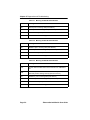
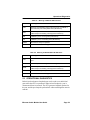
1
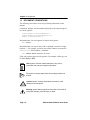
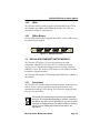
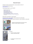
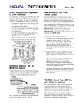
ETHERNET SWITCH MODULE (3E02-04/3E05-04/3E07-04/3E08-04 AND 3E02-08-ATX) USER GUIDE SEGMENT 1 SEGMENT 2 LINK RX OFFLINE X COL TX SEGMENT 1 OFFLINE QUAD IEEE 802.3 / ETHERNET 10BASET SEGMENT 4 SEGMENT 3 LINK RX X COL TX SEGMENT 2 LINK RX X QUAD IEEE 802.3 / ETHERNET AUI SEGMENT 1 X COL TX PWR RESET QUAD IEEE 802.3 / ETHERNET 10BASE2 SEGMENT 4 SEGMENT 3 SEGMENT 2 LINK RX PROC COL TX RX RX RX RX PROC TX TX TX TX PWR RX RX PROC TX TX TX PWR SEGMENT 2 LINK RX RX RX OCTAL IEEE 802.3 / ETHERNET 10BASE-T SEGMENT 1X 2X 3X 4X 5X 6X 7X 8X LINK PROC ACT COL 1 OFFLINE 2 3 4 5 6 7 8 SEGMENT 3 LINK RX COL TX TX SEGMENT 4 RX TX SEGMENT 1 OFFLINE SEGMENT 3 RX PWR TX COL TX QUAD IEEE 802.3 / ETHERNET 10BASE-FL SEGMENT 4 LINK RX RX TX COL TX RX TX LINK RX PROC COL TX PWR NOTICE Cabletron Systems reserves the right to make changes in specifications and other information contained in this document without prior notice. The reader should in all cases consult Cabletron Systems to determine whether any such changes have been made. The hardware, firmware, or software described in this manual is subject to change without notice. IN NO EVENT SHALL CABLETRON SYSTEMS BE LIABLE FOR ANY INCIDENTAL, INDIRECT, SPECIAL, OR CONSEQUENTIAL DAMAGES WHATSOEVER (INCLUDING BUT NOT LIMITED TO LOST PROFITS) ARISING OUT OF OR RELATED TO THIS MANUAL OR THE INFORMATION CONTAINED IN IT, EVEN IF CABLETRON SYSTEMS HAS BEEN ADVISED OF, KNOWN, OR SHOULD HAVE KNOWN, THE POSSIBILITY OF SUCH DAMAGES. Copyright 1996 by Cabletron Systems, Inc., P.O. Box 5005, Rochester, NH 03866-5005 All Rights Reserved Printed in the United States of America Order Number: 9031873-01 May 1996 SPECTRUM and LANView are registered trademarks of Cabletron Systems All other product names mentioned in this manual may be trademarks or registered trademarks of their respective companies. Printed on Ethernet Switch Module User Guide Recycled Paper i Notice FCC NOTICE This device complies with Part 15 of the FCC rules. Operation is subject to the following two conditions: (1) this device may not cause harmful interference, and (2) this device must accept any interference received, including interference that may cause undesired operation. NOTE: This equipment has been tested and found to comply with the limits for a Class A digital device, pursuant to Part 15 of the FCC rules. These limits are designed to provide reasonable protection against harmful interference when the equipment is operated in a commercial environment. This equipment uses, generates, and can radiate radio frequency energy and if not installed in accordance with the operator’s manual, may cause harmful interference to radio communications. Operation of this equipment in a residential area is likely to cause interference in which case the user will be required to correct the interference at his own expense. WARNING: Changes or modifications made to this device which are not expressly approved by the party responsible for compliance could void the user’s authority to operate the equipment. DOC NOTICE This digital apparatus does not exceed the Class A limits for radio noise emissions from digital apparatus set out in the Radio Interference Regulations of the Canadian Department of Communications. Le présent appareil numérique n’émet pas de bruits radioélectriques dépassant les limites applicables aux appareils numériques de la class A prescrites dans le Règlement sur le brouillage radioélectrique édicté par le ministère des Communications du Canada. VCCI NOTICE This equipment is in the 1st Class Category (information equipment to be used in commercial and/or industrial areas) and conforms to the standards set by the Voluntary Control Council for Interference by Information Technology Equipment (VCCI) aimed at preventing radio interference in commercial and/or industrial areas. Consequently, when used in a residential area or in an adjacent area thereto, radio interference may be caused to radios and TV receivers, etc. Read the instructions for correct handling. ii Ethernet Switch Module User Guide Notice CABLETRON SYSTEMS, INC. PROGRAM LICENSE AGREEMENT IMPORTANT: Before utilizing this product, carefully read this License Agreement. This document is an agreement between you, the end user, and Cabletron Systems, Inc. (“Cabletron”) that sets forth your rights and obligations with respect to the Cabletron software program (the “Program”) contained in this package. The Program may be contained in firmware, chips or other media. BY UTILIZING THE ENCLOSED PRODUCT, YOU ARE AGREEING TO BECOME BOUND BY THE TERMS OF THIS AGREEMENT, WHICH INCLUDES THE LICENSE AND THE LIMITATION OF WARRANTY AND DISCLAIMER OF LIABILITY. IF YOU DO NOT AGREE TO THE TERMS OF THIS AGREEMENT, PROMPTLY RETURN THE UNUSED PRODUCT TO THE PLACE OF PURCHASE FOR A FULL REFUND. CABLETRON SOFTWARE PROGRAM LICENSE 1. LICENSE. You have the right to use only the one (1) copy of the Program provided in this package subject to the terms and conditions of this License Agreement. You may not copy, reproduce or transmit any part of the Program except as permitted by the Copyright Act of the United States or as authorized in writing by Cabletron. 2. OTHER RESTRICTIONS. You may not reverse engineer, decompile, or disassemble the Program. 3. APPLICABLE LAW. This License Agreement shall be interpreted and governed under the laws and in the state and federal courts of New Hampshire. You accept the personal jurisdiction and venue of the New Hampshire courts. EXCLUSION OF WARRANTY AND DISCLAIMER OF LIABILITY 1. EXCLUSION OF WARRANTY. Except as may be specifically provided by Cabletron in writing, Cabletron makes no warranty, expressed or implied, concerning the Program (including its documentation and media). CABLETRON DISCLAIMS ALL WARRANTIES, OTHER THAN THOSE SUPPLIED TO YOU BY CABLETRON IN WRITING, EITHER EXPRESSED OR IMPLIED, INCLUDING BUT NOT LIMITED TO IMPLIED WARRANTIES OF MERCHANTABILITY AND FITNESS FOR A PARTICULAR PURPOSE, WITH RESPECT TO THE PROGRAM, THE ACCOMPANYING WRITTEN MATERIALS, AND ANY ACCOMPANYING HARDWARE. 2. NO LIABILITY FOR CONSEQUENTIAL DAMAGES. IN NO EVENT SHALL CABLETRON OR ITS SUPPLIERS BE LIABLE FOR ANY DAMAGES WHATSOEVER (INCLUDING, WITHOUT LIMITATION, DAMAGES FOR LOSS OF BUSINESS, PROFITS, BUSINESS INTERRUPTION, LOSS OF BUSINESS INFORMATION, SPECIAL, INCIDENTAL, CONSEQUENTIAL, OR RELIANCE DAMAGES, OR OTHER LOSS) ARISING OUT OF THE USE OR INABILITY TO USE THIS CABLETRON PRODUCT, EVEN IF CABLETRON HAS BEEN ADVISED OF THE POSSIBILITY OF SUCH DAMAGES. BECAUSE SOME STATES DO NOT ALLOW THE EXCLUSION OR LIMITATION OF LIABILITY FOR CONSEQUENTIAL OR INCIDENTAL DAMAGES, OR ON THE DURATION OR LIMITATION OF IMPLIED WARRANTIES, IN SOME INSTANCES THE ABOVE LIMITATIONS AND EXCLUSIONS MAY NOT APPLY TO YOU. Ethernet Switch Module User Guide iii Notice UNITED STATES GOVERNMENT RESTRICTED RIGHTS The enclosed product (a) was developed solely at private expense; (b) contains “restricted computer software” submitted with restricted rights in accordance with Section 52227-19 (a) through (d) of the Commercial Computer Software - Restricted Rights Clause and its successors, and (c) in all respects is proprietary data belonging to Cabletron and/or its suppliers. For Department of Defense units, the product is licensed with “Restricted Rights” as defined in the DoD Supplement to the Federal Acquisition Regulations, Section 52.227-7013 (c) (1) (ii) and its successors, and use, duplication, disclosure by the Government is subject to restrictions as set forth in subparagraph (c) (1) (ii) of the Rights in Technical Data and Computer Software clause at 252.2277013. Cabletron Systems, Inc., 35 Industrial Way, Rochester, New Hampshire 03867-0505. iv Ethernet Switch Module User Guide CONTENTS CHAPTER 1 INTRODUCTION 1.1 Document Conventions ............................................................... 1-2 1.2 Related Manuals.......................................................................... 1-3 1.3 Getting Help................................................................................. 1-3 1.4 General Description..................................................................... 1-4 1.5 3E02-04 Ethernet Switch Module ................................................ 1-5 1.5.1 Connectors ..................................................................... 1-6 1.5.2 LEDs ............................................................................... 1-6 1.5.3 Offline Button .................................................................. 1-6 1.6 3E07-04 Ethernet Switch Module ................................................ 1-6 1.6.1 Connectors ..................................................................... 1-7 1.6.2 LEDs ............................................................................... 1-7 1.6.3 Offline Button .................................................................. 1-7 1.7 3E08-04 Ethernet Switch Module ................................................ 1-7 1.7.1 Connectors ..................................................................... 1-8 1.7.2 LEDs ............................................................................... 1-8 1.7.3 Offline Button .................................................................. 1-8 1.8 3E05-04 Ethernet Switch Module ................................................ 1-8 1.8.1 Connectors ..................................................................... 1-8 1.8.2 LEDs ............................................................................... 1-9 1.8.3 Offline Button .................................................................. 1-9 1.9 3E02-08-ATX Ethernet Switch Module........................................ 1-9 1.9.1 Connectors ..................................................................... 1-9 1.9.2 LEDs ............................................................................. 1-10 1.9.3 Offline Button ................................................................ 1-10 CHAPTER 2 CONNECTING TO THE NETWORK 2.1 Introduction.................................................................................. 2-1 2.2 Power-up LED Sequence ............................................................ 2-1 2.3 Connecting to a Network ............................................................. 2-2 2.3.1 Connecting the 3E02-04 Ethernet Switch Module .......... 2-3 2.3.2 Connecting the 3E07-04 Ethernet Switch Module .......... 2-3 2.3.3 Connecting the 3E08-04 Ethernet Switch Module .......... 2-4 2.3.4 Connecting the 3E05-04 Ethernet Switch Module .......... 2-5 2.3.5 Connecting the 3E02-08-ATX Ethernet Switch Module .. 2-6 Ethernet Switch Module User Guide v Contents CHAPTER 3 CONFIGURING 3.1 Introduction ..................................................................................3-1 3.2 Connecting the Local Console Manager......................................3-2 3.3 LCM Commands ..........................................................................3-2 CHAPTER 4 MONITORING 4.1 Displaying Port Status..................................................................4-1 4.1.1 Status Command.............................................................4-1 CHAPTER 5 DIAGNOSTICS AND TROUBLESHOOTING 5.1 Power-up Diagnostics ..................................................................5-1 5.1.1 Power-up Tests ...............................................................5-1 5.1.2 Power-Up Results ...........................................................5-1 5.2 Operational Diagnostics ...............................................................5-3 5.2.1 Diagnostic Results...........................................................5-4 5.3 Troubleshooting ...........................................................................5-4 5.3.1 If The Module Fails To Power Up....................................5-4 5.3.2 Connectivity Problems.....................................................5-5 CHAPTER 6 ADDING/SWAPPING MODULES 6.1 Unpacking The Ethernet Switch Module ......................................6-1 6.2 Adding An Ethernet Switch Module .............................................6-1 6.3 Swapping An Ethernet Switch Module.........................................6-2 APPENDIX A TECHNICAL SPECIFICATIONS APPENDIX B CABLES B.1 Types/Connectors ....................................................................... B-1 B.2 Cable Specifications ................................................................... B-1 B.3 10BASE-T Pin Assignments ....................................................... B-3 B.3.1 Crossover Wiring ............................................................ B-4 B.3.2 Straight-Through Wiring.................................................. B-5 B.4 AUI Pin Assignments .................................................................. B-5 B.5 5 - 4 - 3 Rule ............................................................................... B-6 B.5.1 Definitions ....................................................................... B-7 INDEX vi Ethernet Switch Module User Guide CHAPTER 1 INTRODUCTION This manual is for system administrators responsible for configuring, monitoring and maintaining the ATX. It should be used with the ATX User Guide and the ATX MIB Reference Guide. The contents of each chapter are described below. • Chapter 1, Introduction, provides a general description of the modules. • Chapter 2, Connecting to the Network, describes how to physically attach a module to an Ethernet network. • Chapter 3, Configuring, discusses the software configuration options for the modules. • Chapter 4, Monitoring, provides information on Ethernet port statistics obtained via LCM. • Chapter 5, Diagnostics and Troubleshooting, discusses identifying possible problems with the modules. • Chapter 6, Adding/Swapping Modules, gives instructions for adding and replacing an Ethernet module. • Appendix A, Technical Specifications, lists the pertinent technical information about the modules. • Appendix B, Cables, lists pertinent cabling information about the modules. Ethernet Switch Module User Guide Page 1-1 Chapter 1: Introduction 1.1 DOCUMENT CONVENTIONS The following conventions are used in presenting information in this manual: Commands, prompts, and information displayed by the computer appear in Courier typeface: Current Number of Station Addresses: 5 Current Number of Learned Addresses: 133 Number of Defined Filters: 4 Information that you enter appears in Courier bold typeface: ATX >status Information that you need to enter with a command is enclosed in angle brackets <>. For example, you must enter a MAC address to execute the address matrix <MAC address> command: ATX >address matrix 00:40:27:04:1a:0f Field value options appear in bold typeface. For example, a filter type can be either Entry or Exit. NOTE TIP ! Note symbol. Calls the reader’s attention to any item of information that may be of special importance. Tip symbol. Conveys helpful hints concerning procedures or actions. Caution symbol. Contains information essential to avoid damage to the equipment. CAUTION Warning symbol. Warns against an action that could result in equipment damage, personal injury or death. Page 1-2 Ethernet Switch Module User Guide Related Manuals 1.2 RELATED MANUALS You may need to refer to the following documentation when you are using the Ethernet module: • ATX User Guide – contains installation and configuration instructions for the ATX. • ATX MIB Reference Guide – describes the use of Cabletron’s enterprise MIB. If you need internetworking reference material, you may find the following books helpful: • Interconnections, Bridges and Routers, Radia Perlman, Addison Wesley 1992. • Internetworking with TCP/IP: Protocols, and Architecture (2nd edition), Volumes I and II, Douglas Comer, Prentice Hall 1991. • The Simple Book, An Introduction to Management of TCP/IP-based Internets, Marshall T. Rose, Prentice Hall 1991. 1.3 GETTING HELP If you need additional support related to this device, or if you have any questions, comments, or suggestions concerning this manual, contact Cabletron Systems Technical Support: By phone By CompuServe By Internet mail By FTP Login Password (603) 332-9400 Monday – Friday; 8 A.M. – 8 P.M. Eastern Time GO CTRON from any ! prompt [email protected] ctron.com (134.141.197.25) anonymous your email address Ethernet Switch Module User Guide Page 1-3 Chapter 1: Introduction 1.4 GENERAL DESCRIPTION Cabletron Systems Ethernet Switch Modules connect the ATX to a maximum of four individual Ethernet IEEE 802.3 LANs. The Ethernet Switch Module (3E02-08-ATX) connects to a maximum of eight Ethernet IEEE 802.3 LANs. Both module types enable connectivity to FDDI, Token Ring, and Ethernet networks, and can be configured to support Transparent Spanning Tree, Source Routing, or Source Routing Transparent Bridging on each of the ports. The ATX can translate higher level protocols to allow communication between end-nodes on Ethernet as well as FDDI or Token Ring. Protocols translated include TCP/IP, Novell NetWare, and AppleTalk Phase II. The four port Ethernet Switch Module is available in four versions to support various cabling types: • 3E02-04: provides four Unshielded Twisted Pair (UTP) connections • 3E07-04: provides four thin coaxial cable connections • 3E08-04: provides four multimode fiber optic connections • 3E05-04: provides four Attachment Unit Interface (AUI) connections The 3E02-08-ATX module provides eight UTP connections. The Ethernet Switch Modules include processing circuitry for receiving and forwarding data packets between the connected devices. Each module contains an offline button and several LEDs that indicate the module’s and individual ports’ operational status. The four port modules may be installed in any of the five interface slots and the ATX can simultaneously support up to five Ethernet Switch Modules. The 3E02-08-ATX module may be installed in any of the five interface slots in a ATX, and the ATX can simultaneously support up to five eight port modules. Each module provides connectivity to the multiple LANs. Page 1-4 Ethernet Switch Module User Guide 3E02-04 Ethernet Switch Module Each module provides connectivity to the multiple LANs. Since packets are bridged/routed across Ethernet Switch Modules only when it is necessary to reach the end device, each four port module can support four distinct 10 Mbps LANs, while the eight port module supports eight distinct 10 Mbps LANs. S s B bp ET G U 1.6 R ES A LY P LY P P S S U P S S TU TU TU TA TA TA S S E R O E IN B W G R N O TU E P TM S FastNET ATX NMS PORT PACKET PROCESSING ENGINE POWER OCTAL IEEE 802.3 / ETHERNET 10BASE-T SEGMENT 1X 2X 3X 4X 5X 6X 7X 8X LINK PROC ACT COL 1 2 3 4 5 6 7 8 OFFLINE RING 1 RX ST RING 2 RX ST TX 16 OFFLINE SEGMENT 1 TX 16 OPTICAL BYPASS TX RX PROC RX LK TX LK TX PWR RX INTELLIGENT FDDI FDDI MIC B TH R W U R A R P X PR O C FDDI MIC A RX TX 16 PWR QUAD FAST ETHERNET / 802.3 100BASE-FX SEGMENT 4 TX RX LK TX RX SEGMENT 3 TX RX LK TX PWR QUAD IEEE 802.5 TOKEN RING (UTP) RING 4 RX ST PROC TX 16 SEGMENT 2 TX RX OFFLINE RING 3 RX ST RING A OFFLINE MULTI-MODE RING B MULTI-MODE TX PWR QUAD IEEE 802.3 / ETHERNET 10BASE2 SEGMENT 4 S B 1 N R H /T .3 2 0 8 IE D A U Q 1 T N M G E S E IN L F O 2 T N M G E S 3 T N M G E S 4 T N M G E S X R X R X R X R X T X T X T X T C O R P R W P SEGMENT 1 OFFLINE SEGMENT 2 SEGMENT 3 RX RX RX RX PROC TX TX TX TX PWR Figure 1-1 ATX Front Panel 1.5 3E02-04 ETHERNET SWITCH MODULE The 3E02-04 (Figure 1-2) provides connection for four independent 10BASE-T LANs to the ATX backplane and packet processing module. It includes processing circuitry for receiving and forwarding packets between the connected 10BASE-T LANs. The module provides several LEDs to indicate the module’s operational status. The module supports twisted pair Ethernet and the IEEE 802.3 10BASE-T specification. Ethernet Switch Module User Guide Page 1-5 Chapter 1: Introduction 1.5.1 Connectors The 3E02-04 includes eight 8-pin RJ45 ports for attachment directly to the network through UTP cabling. The ATX power supply provides the power for the module. NOTE 1.5.2 An internal receive/transmit pair crossover is provided in the second connector (far right, marked with an X) on each port. This means that when either a station or server is directly attached to a 3E02-04 port, you can choose to use either straight-through or crossover cabling. For more cabling and crossover information, see Appendix B. LEDs The 3E02-04 provides a total of 18 green LEDs labeled LNK, COL, RX and TX for each segment, plus PROC and PWR for the module. The LEDs are described in Chapter 5, Diagnostics and Troubleshooting, of this manual. 1.5.3 Offline Button Use the offline button before swapping the module, to take it offline until the replacement is installed. SEGMENT 1 SEGMENT 2 LINK RX OFFLINE X COL TX Figure 1-2 SEGMENT 3 LINK RX X COL TX QUAD IEEE 802.3 / ETHERNET 10BASET SEGMENT 4 LINK RX X COL TX LINK RX PROC X COL TX PWR 3E02-04 Module Front Panel 1.6 3E07-04 ETHERNET SWITCH MODULE The 3E07-04 (Figure 1-3) provides connection for four independent 10BASE2 LANs to the ATX backplane and packet processing module. It includes processing circuitry for receiving and forwarding packets between the connected 10BASE2 LANs. The 3E07-04 contains several LEDs to indicate the module’s operational status. The 3E07-04 supports thin coaxial cable Ethernet and the IEEE 802.3 10BASE2 specification. Page 1-6 Ethernet Switch Module User Guide 3E08-04 Ethernet Switch Module 1.6.1 Connectors The 3E07-04 includes four pairs of BNC barrel connectors for thin coaxial cabling. Each of the four segments provides an internal BNC T-connector, therefore an external T-connector is not required. The ATX power supply provides the power for the module. 1.6.2 LEDs The 3E07-04 contains a total of 10 green LEDs labeled RX and TX for each segment, plus PROC and PWR for the module. The LEDs are described in Chapter 5 of this manual. 1.6.3 Offline Button Use the offline button before swapping the module, to take it offline until the replacement is installed. SEGMENT 1 OFFLINE SEGMENT 2 QUAD IEEE 802.3 / ETHERNET 10BASE2 SEGMENT 4 SEGMENT 3 RX RX RX RX PROC TX TX TX TX PWR Figure 1-3 3E07-04 Front Panel 1.7 3E08-04 ETHERNET SWITCH MODULE The 3E08-04 (Figure 1-4) provides connection for four independent multimode 10BASE-FL LANs to the ATX backplane and packet processing module. It includes processing circuitry for receiving and forwarding packets between the connected 10BASE-FL LANs. The 3E08-04 contains several LEDs to indicate the module’s operational status. The 3E08-04 supports Ethernet and the IEEE 802.3 10BASE-FL specification. Ethernet Switch Module User Guide Page 1-7 Chapter 1: Introduction 1.7.1 Connectors The 3E08-04 includes four pairs of fiber optic ST connectors for fiber optic cabling. Receive (RX) and transmit (TX) connectors are clearly marked on the front panel of the module. The ATX power supply provides the power for the module. 1.7.2 LEDs The 3E08-04 contains a total of 18 green LEDs labeled LNK, COL, RX and TX for each segment, plus PROC and PWR for the module. The LEDs are described in Chapter 5 of this manual. 1.7.3 Offline Button Use the offline button before swapping the module, to take it offline until the replacement is installed. SEGMENT 1 SEGMENT 2 LINK RX OFFLINE RX TX COL TX SEGMENT 3 LINK RX RX Figure 1-4 TX COL TX QUAD IEEE 802.3 / ETHERNET 10BASE-FL SEGMENT 4 LINK RX RX TX COL TX RX TX LINK RX PROC COL TX PWR 3E08-04 Front Panel 1.8 3E05-04 ETHERNET SWITCH MODULE The 3E05-04 (Figure 1-5) provides connection for four independent Ethernet IEEE 802.3 LANs to the ATX backplane and packet processing module. It includes processing circuitry for receiving and forwarding packets between the connected LANs. The 3E05-04 contains several LEDs to indicate the module’s operational status. The 3E05-04 supports Ethernet version 2 and the IEEE 802.3 specification. 1.8.1 Connectors The 3E05-04 includes four DB15 AUI connectors which you can connect to an AUI drop cable or to a transceiver attached to a LAN. Page 1-8 Ethernet Switch Module User Guide 3E02-08-ATX Ethernet Switch Module 1.8.2 LEDs The 3E05-04 contains a total of 10 green LEDs labeled RX and TX for each segment, plus PROC and PWR for the module. The LEDs are described in Chapter 5 of this manual. 1.8.3 Offline Button Use the offline button before swapping the module, to take it offline until the replacement is installed. QUAD IEEE 802.3 / ETHERNET AUI SEGMENT 1 RESET SEGMENT 2 SEGMENT 3 SEGMENT 4 RX RX RX RX PROC TX TX TX TX PWR Figure 1-5 3E05-04 Front Panel 1.9 3E02-08-ATX ETHERNET SWITCH MODULE The 3E02-08-ATX (Figure 1-6) provides connection for eight independent 10BASE-T LANs to the ATX. It includes processing circuitry for receiving and forwarding packets between the connected 10BASE-T LANs. The 3E02-08-ATX contains several LEDs to indicate the module’s operational status. The 3E02-08-ATX supports UTP cabling and the IEEE 802.3 10BASE-T specification. 1.9.1 Connectors The 3E02-08-ATX includes eight 8-pin RJ45 receptacle connectors with built-in crossover that you can attach directly to the network using unshielded twisted pair (UTP) cabling. The ATX power supply provides the power for the module. NOTE An internal receive/transmit pair crossover is provided within each port. This means that depending on whether crossover is provided on the device you’re connecting to, you can use either crossover or straight-through UTP cable to connect a device to a port. For more cabling and crossover information, see Appendix B. Ethernet Switch Module User Guide Page 1-9 Chapter 1: Introduction 1.9.2 LEDs The 3E02-08-ATX contains a total of 26 green LEDs labeled LINK, ACT, COL for each segment, plus PROC and PWR for the module. The LEDs are described in Chapter 5 of this manual. 1.9.3 Offline Button Use the offline button before swapping the module, to take it offline until the replacement is installed. OCTAL IEEE 802.3 / ETHERNET 10BASE-T SEGMENT 1X 2X 3X 4X 5X 6X 7X 8X LINK PROC ACT COL 1 2 3 4 OFFLINE Figure 1-6 Page 1-10 5 6 7 8 PWR 3E02-08-ATX Front Panel Ethernet Switch Module User Guide CHAPTER 2 CONNECTING TO THE NETWORK 2.1 INTRODUCTION This chapter provides reference material and instructions for a network administrator configuring the Ethernet Switch Modules. For instructions on adding a module to the ATX, see Chapter 6, Adding/Swapping Modules. 2.2 POWER-UP LED SEQUENCE Power-up the ATX and observe the LED sequence. It takes about 1 minute for the ATX to complete the power-up diagnostics. The ATX begins system diagnostics on the PPE (topmost module) and then individually on each installed module progressing from top to bottom. The specific power-up tests run on the Ethernet switch modules are: • ROM checksum test • Instruction memory test • Memory map tests • Interrupt tests • Ethernet data loopback test Ethernet Switch Module User Guide Page 2-1 Chapter 2: Connecting to the Network The power-up LED sequence for an Ethernet Switch Module not attached to a network is as follows: 1. All LEDs flash. 2. The PWR LED remains on, and the TX and RX LEDs flash. 3. 3E02-04: The PROC LED comes on for 5 seconds, then blinks, then remains lit. The RX, COL, and TX LEDs flash for 100 milliseconds. 3E07-04: The PROC, RX, and TX LEDs come on for 5 seconds, then the RX and TX LEDs go off. The PROC LED remains lit. 3E08-04: The PROC LED comes on for 5 seconds, then blinks, then remains lit. The RX, COL, and TX LEDs flash for 100 milliseconds. 3E05-04: The PROC, RX, and TX LEDs come on for 5 seconds, then the RX and TX LEDs go off. The PROC LED remains lit. 4. After a few seconds the module reboots and the PROC LED comes on. 5. All other LED activity beyond this point is a function of the configuration and connection of the ATX. 2.3 CONNECTING TO A NETWORK To connect an Ethernet Switch Module to an Ethernet network, use the following types of Ethernet cable: • Unshielded twisted pair (10BASE-T) • Thin coaxial cabling (10BASE2) • Multimode fiber optics (10BASE-FL) • Attachment Unit Interface cabling (10BASE5) To connect the 3E02-08-ATX to an Ethernet network, use UTP cable (10BASE-T). Page 2-2 Ethernet Switch Module User Guide Connecting to a Network 2.3.1 Connecting the 3E02-04 Ethernet Switch Module You can connect each of the four 10BASE-T ports on the 3E02-04 to a 10BASE-T port on a device such as a workstation, server, hub, etc. using unshielded twisted pair wiring. The second RJ45 connector (far right, marked with an X) for each port on the 3E02-04 provide internal crossover. This means that you can choose which type of UTP cable (crossover or straight-through) you need to connect devices to these ports. Refer to Appendix B, Cables for cable specifications. Connect one end of a UTP cable to an open 10BASE-T port on the 3E02-04 and the other end to the RJ45 port on the device (see Figure 2-1). If the device doesn’t have an RJ45 port, connect a 10BASE-T transceiver directly to the device’s AUI port, and then connect the UTP cable to the RJ45 port on the transceiver. SEGMENT 1 OFFLINE X SEGMENT 2 QUAD IEEE 802.3 / ETHERNET 10BASET SEGMENT 4 LINK RX LINK RX COL TX COL TX COL TX Figure 2-1 2.3.2 SEGMENT 3 LINK RX X X LINK RX PROC X COL TX PWR Connecting to the 3E02-04 Connecting the 3E07-04 Ethernet Switch Module You can connect each of the four pairs of BNC ports on the 3E07-04 to a thin coax network or port. Each segment has two female BNC connectors which form an internal T connection, eliminating the need for an external BNC T-connector. Attach the male end of a thin coax to the first BNC connector (see Figure 2-2). Connect either another thin coax cable section or a 50-ohm terminator to the other BNC connector on the same segment on the 3E07-04 module. Refer to Appendix B, Cables for cable specifications. Ethernet Switch Module User Guide Page 2-3 Chapter 2: Connecting to the Network You do not need to attach terminators to unattached segments. NOTE SEGMENT 1 OFFLINE SEGMENT 2 RX RX RX PROC TX TX TX TX PWR Figure 2-2 2.3.3 QUAD IEEE 802.3 / ETHERNET 10BASE2 SEGMENT 4 SEGMENT 3 RX Connecting the 3E07-04 Connecting the 3E08-04 Ethernet Switch Module You can connect each of the four pairs of ST fiber ports on the 3E08-04 to a 10BASE-FL port on a device such as a hub, etc. using fiber optic cable. Each fiber segment has a pair of female ST connectors clearly marked as “RX” and “TX.” Attach the transmit (TX) connector on the 3E08-04 to the receive (RX) connector on the attached device. Similarly, the receive (RX) connector on the 3E08-04 must be connected to the transmit (TX) connector on the attached device (see Figure 2-3). Refer to Appendix B for cable specifications. SEGMENT 1 RX TX QUAD IEEE 802.3 / ETHERNET 10BASE-FL SEGMENT 4 LINK RX LINK RX PROC COL TX COL TX COL TX COL TX PWR RX Figure 2-3 Page 2-4 SEGMENT 3 LINK RX TX RX TX RX TX To RX on device To TX on device OFFLINE SEGMENT 2 LINK RX Connecting the 3E08-04 Ethernet Switch Module User Guide Connecting to a Network 2.3.4 Connecting the 3E05-04 Ethernet Switch Module You can connect each of the four AUI connectors on the 3E05-04 to an Ethernet network. To connect the 3E05-04 module to a thick coax network, you must use an AUI drop cable and a tap-type transceiver: 1. Attach a tap-type transceiver to the thick coax cable. Refer to the transceiver manufacturer’s manual for installation instructions. 2. Connect one end of the AUI drop to an AUI port on the 3E05-04 and the other end to the tap-type transceiver. a. Slide the hold-down clip on the female DB15 connector on the module to the open position. b. Attach the male DB15 connector on the drop cable, and then slide the clip back to the closed position. To connect the 3E05-04 to an alternate media network, you must use a transceiver connected to the module’s AUI port. There are many types of Ethernet transceivers available; the transceiver must be matched to the Ethernet cable type. Refer to Appendix B for cable specifications. QUAD IEEE 802.3 / ETHERNET AUI SEGMENT 1 RESET SEGMENT 2 SEGMENT 3 SEGMENT 4 RX RX RX RX PROC TX TX TX TX PWR Figure 2-4 Connecting the 3E05-04 Ethernet Switch Module User Guide Page 2-5 Chapter 2: Connecting to the Network 2.3.5 Connecting the 3E02-08-ATX Ethernet Switch Module You can connect each of the eight ports on the 3E02-08-ATX to a 10BASE-T port on a device such as a workstation, server, hub, etc. using UTP wiring. The RJ45 ports on the 3E02-08-ATX provide internal crossover, which means that, depending on whether crossover is provided on the device you’re connecting to, you can use either crossover or straight-through UTP cable to connect a device to a port. Refer to Appendix B for cable specifications. Connect one end of a UTP cable to an open 10BASE-T port on the 3E02-08-ATX and the other end to the RJ45 port on the device (see Figure 2-5). If the device doesn’t have an RJ45 port, connect a 10BASE-T transceiver directly to the device’s AUI port, and then connect the UTP cable to the RJ45 port on the transceiver. OCTAL IEEE 802.3 / ETHERNET 10BASE-T SEGMENT 1X 2X 3X 4X 5X 6X 7X 8X LINK PROC ACT COL 1 2 3 4 5 6 OFFLINE Figure 2-5 Page 2-6 7 8 PWR Connecting the 3E02-08-ATX Ethernet Switch Module User Guide CHAPTER 3 CONFIGURING 3.1 INTRODUCTION You can configure the Ethernet Switch Modules using the following tools: • Local Console Manager (LCM) – allows you to monitor, manage, and configure your ATX through an out-of-band RS-232 connection • SPECTRUM Element Manager or the full SPECTRUM Enterprise network management platform • Any SNMP compliant network management system For more details about LCM, see your ATX User Guide. For details about the other network management software, refer to the product’s documentation. The following attributes are configurable using LCM: • Port’s IP address for originating and receiving IP packets • Enabling/disabling a port’s Transparent Spanning Tree, Source Routing or Source Routing Transparent mode Additionally, you can configure the following attributes using network management software platforms (refer to the network management software documentation for specific instructions): • Parameters for diagnostic loopback testing of a port • Protocol translations Filtering normally occurs as part of the Transparent Spanning Tree and Source Routing algorithms. In addition, you can establish configurable criteria for filtering, to allow greater management control for security or network congestion reasons. All configured filtering criteria are Ethernet Switch Module User Guide Page 3-1 Chapter 3: Configuring maintained in non-volatile memory and are saved across power cycles. Filtering information is covered in the ATX User Guide. 3.2 CONNECTING THE LOCAL CONSOLE MANAGER Connect the Local Console Manager (LCM) to the ATX. Refer to Chapter 2, Connecting to the Network, of the ATX User Guide for specific instructions. Make sure the ATX is powered on and press <Return> a few times. When the ATX > prompt appears, LCM is ready to use. 3.3 LCM COMMANDS To configure an Ethernet Switch Module, refer to the ATX User Guide for LCM commands generic to all modules. Familiarize yourself with LCM before configuring the module. Specific instructions for displaying the port status are given in Chapter 4, Monitoring. Page 3-2 Ethernet Switch Module User Guide CHAPTER 4 MONITORING 4.1 DISPLAYING PORT STATUS Using LCM, you can obtain the status of ports by typing status for the appropriate port. A sample display is shown below. 4.1.1 Status Command ATX >status 2 Port 2 (1st port on module 3) status Type: Ethernet/802.3 CSMA/CD Bridging: Transparent/Translating Routing: IP Routing RIP Enabled/Disabled: Bridging/Routing functions enabled Spanning Tree: Forwarding Pkts Transmitted: 503 Pkts Received: 89711 Small Buffers: 23 Rx_Q Overflows: 10 Carrier Losses: 9 Total Collisions: 184 Excess Collisions: 5 Rx FCS/Align Errs: 0 Internal Rx Errors: 0 Internal Tx Errors: 0 The status of the port includes the following information: • Bridging - which functions have been enabled for bridging (see the bridge command). • Routing - which functions have been enabled for routing (see iproute and ipxroute commands in your NMS manual). • Enabled/Disabled - enabled if it is operational or, disabled if you used the disable command to disable it. If the port is enabled but not operational, its status will be broken. (A port could be broken if it is so badly misconfigured as to be unusable. You might also see a status of broken if an FDDI or Token Ring port can’t connect to a logical ring, or if an Ethernet port continually fails as it tries to transmit.) Ethernet Switch Module User Guide Page 4-1 Chapter 4: Monitoring • Spanning Tree - the port’s Spanning Tree state, which could be any one of the following states: - Blocking - The port is not currently the designated port to a LAN and is therefore not forwarding any packets. (This means there is another route to that LAN and, since the Spanning Tree protocol does not allow simultaneous redundant paths, this port is blocked. If the other route to that LAN goes down, this port would then start forwarding packets.) - Listening - The port is listening for other bridges on the network to determine if it should go to the forwarding or blocking state. - Learning - The port is listening for other bridges on the network and making a table of addresses from packets that it has received. Once the port goes to the forwarding state, it can then use the address information it has learned. - Forwarding - The port is the designated port for the LAN and is forwarding packets and sending out bridge protocol packets. - Broken - The port is not forwarding packets. Reasons include no cable connected, no link status, or network management has disabled the port. - Disabled - The port is not configured for Spanning Tree. • Pkts Transmitted - number of packets transmitted from the port. This includes any packets that might have experienced transmission errors. (The port’s statistics are reset whenever the port is started.) • Packets Received - number of good packets received through the port. Packets with reception errors are not included, nor are packets local to that segment that are hardware filtered. • Small Buffers - number of buffers currently assigned to the port (see RX_Q Overflows below). • RX_Q Overflows - number of incoming packets dropped by the port due to a lack of buffers. After a reboot, the ATX tries to automatically re-allocate the Small Buffers among the ports so that the total number of RX_Q Overflows is minimized. • Carrier Losses - number of packet transmissions that detected a loss of carrier (usually a transceiver problem). Page 4-2 Ethernet Switch Module User Guide Displaying Port Status • Total Collisions - number of collisions during packet transmissions. • Excess Collisions - number of packet transmissions that were aborted due to 16 collisions (usually a transceiver problem). • RX FCS/Align Errs - number of times a received packet was discarded due to a bad checksum or Frame Alignment error. • Internal RX Errs - number of times an inbound packet was dropped due to an internal error. (Whenever a packet is dropped due to TX_Q Overflows, Internal RX Errs may also be incremented.) • Internal TX Errs - number of times a packet transmission was aborted due to an internal error. NOTE All of the counter values are reset to zeros if the ATX is rebooted or if the module housing that port is halted and restarted. Ethernet Switch Module User Guide Page 4-3 Chapter 4: Monitoring Page 4-4 Ethernet Switch Module User Guide CHAPTER 5 DIAGNOSTICS AND TROUBLESHOOTING 5.1 POWER-UP DIAGNOSTICS Built-in diagnostic capabilities for the Ethernet Switch Modules include: • Power-up diagnostics, which are run every time an Ethernet Switch Module is brought online. • Front panel status LEDs. • Local and remote loopback tests. • Temperature sensors. 5.1.1 Power-up Tests The power-up diagnostics assure that the ATX and all the installed modules are operational. During diagnostic mode, the status LEDs are used differently than during normal operation. When the ATX is powered-up, it automatically senses the installed boards and reassigns port numbers starting with the PPE as port 1. During a normal power-up test, the diagnostics test the entire ATX starting with the PPE and proceeding slot by slot from the top down. The normal power-up sequence is described in Chapter 2, Connecting to the Network. 5.1.2 Power-Up Results After completion of the power-up diagnostic sequence, all status LEDs on the ATX front panel should be on (lit), indicating that the modules have passed the power-up tests. Refer to Tables 5-1 through 5-5. If an Ethernet Switch Module fails a critical test, it is automatically disabled. Ethernet Switch Module User Guide Page 5-1 Chapter 5: Diagnostics and Troubleshooting Table 5-1 Meaning of 3E05-04 LED Indicators LED Meaning RX Ethernet port is receiving data (LED flashes) TX Ethernet port is transmitting data (LED flashes) PROC Processor is ready for operation POWER Module hardware is receiving power Table 5-2 Meaning of 3E07-04 LED Indicators LED Meaning RX 10BASE-2 port is receiving data (LED flashes) TX 10BASE-2 port is transmitting data (LED flashes) PROC Processor is ready for operation POWER Module hardware is receiving power Table 5-3 Meaning of 3E08-04 LED Indicators LED Meaning COL Receiver and transmitter active at the same time on 10BASE-FL port LNK 10BASE-FL port is connected to another device by a cable; both cable and port are working correctly (LED is turned on) RX 10BASE-FL port is receiving data (LED flashes) TX 10BASE-FL port is transmitting data (LED flashes) PROC Processor is ready for operation POWER Module hardware is receiving power Page 5-2 Ethernet Switch Module User Guide Operational Diagnostics Table 5-4 Meaning of 3E02-04 LED Indicators LED Meaning COL Receiver and transmitter active at the same time on 10BASE-T port and when port enters jabber state (LED flashes) LNK 10BASE-T port is connected to another device by a cable; both cable and port are working correctly (LED is turned on) RX 10BASE-T port is receiving data (LED flashes) TX 10BASE-T port is transmitting data (LED flashes) PROC Processor is ready for operation POWER Module hardware is receiving power Table 5-5 Meaning of 3E02-08-ATX LED Indicators LED Meaning COL Receiver and transmitter active at the same time on 10BASE-T port ACT 10BASE-T port is receiving and transmitting data LINK 10BASE-T port is connected to another device by a cable; both cable and port are working correctly (LED is turned on) PROC Processor is ready for operation POWER Module hardware is receiving power 5.2 OPERATIONAL DIAGNOSTICS Built-in local and remote loopback tests can be used to test individual ports while the ATX is operational. When in local loopback, a port is disconnected from its network. The ATX generates loopback packets for the port, and the port loops the packets back without sending them onto its network. Ethernet Switch Module User Guide Page 5-3 Chapter 5: Diagnostics and Troubleshooting During a remote loopback test, the port is in normal operation, sending and receiving packets to its network. The ATX generates loopback packets which are sent out of the port to a particular destination device on the port’s network. The destination device echoes the packet back onto the network, and the originating port receives the packet. For both types of tests, normal operation is indicated when generated packets are received back (after looping) without errors. For remote loopback tests, the ATX creates LLC Type 1 test packets for LANs and PPP echo-request packets for WANs and UARTs. Both types of loopback tests can be initiated by the NMS, and test results are reported to the NMS. 5.2.1 Diagnostic Results ATX diagnostic results are indicated in two ways: by observing the front panel LEDs (which are explained later in this chapter) or by reading NMS trap messages. Both power-up and loopback diagnostics produce traps, which are sent to the NMS and may be logged for future reference. In some cases it may be more convenient to simply observe the LEDs, but in most cases traps provide more information. There are no LEDs for the loopback tests—the results of these tests must be observed (i.e., accurate packet transmission) or read using an NMS (i.e., examine traps). 5.3 TROUBLESHOOTING 5.3.1 If The Module Fails To Power Up If the Ethernet Switch Module fails to power up when the ATX is on and functioning properly: 1. Check the status of ports using LCM. 2. Reset the Ethernet Switch Module and observe the power-up sequence again. 3. If the sequence is still abnormal: a. Take the module offline by pressing the OFFLINE button on the module’s front panel. Page 5-4 Ethernet Switch Module User Guide Troubleshooting b. Remove the interface module by unscrewing the two retaining screws on the module’s front panel. Pull the module out using the “ears” on the front panel. c. Carefully but firmly press down on all socketed components. d. Re-install the module. Make sure the module is properly seated and tighten the retaining screws. e. Reset the ATX and observe the power-up sequence. 4. If it is still abnormal, contact Cabletron Systems Technical Support. 5.3.2 Connectivity Problems If the Ethernet Switch Module powers up normally but the workstations are unable to communicate: 1. Check the LEDs for abnormalities which may help indicate the source of the problem. (LED behavior during normal operation is explained earlier in this chapter.) 2. Check the status of the ports using LCM. 3. Check for loose connections between the module, transceivers, and devices. 4. Check that the proper type of cable is used: crossover or straight-through depending on the configuration; distance limitations are adhered to; the 5-4-3 rule is not violated, etc. (Refer to Appendix B for cabling information and the 5-4-3 rule.) Ethernet Switch Module User Guide Page 5-5 Chapter 5: Diagnostics and Troubleshooting Page 5-6 Ethernet Switch Module User Guide CHAPTER 6 ADDING/SWAPPING MODULES Once you have received your ATX, you may want to add a new module to expand your network bandwidth, replace a module with a module of a different type, or swap a module with another module of the same type. If you are: • Adding an Ethernet switch module to a previously vacant slot or to a slot that had a different type of module, refer to the section Adding an Ethernet Switch Module below, for instructions. • Replacing a module, refer to Section 6.3, Swapping an Ethernet Switch Module, on page 6-2 for instructions. Before adding or swapping modules, refer to the latest version of the ATX Release Notes (provided with your ATX software) for information about software and hardware version numbers and compatibility. 6.1 UNPACKING THE ETHERNET SWITCH MODULE Unpack the Ethernet switch module carefully, handling it by the edges only, and inspect it for possible damage. If any damage is evident, contact Cabletron Systems. Save the original container and antistatic wrap in case the module needs to be repaired. 6.2 ADDING AN ETHERNET SWITCH MODULE If the module you are adding is of a different type than the module that previously occupied that slot, or if the slot was previously vacant, you have to reboot the ATX so it will recognize the new module. 1. Make sure the ATX is powered off. 2. Remove the network connections from the module you are going to replace. 3. Loosen the screws at each end of the front panel of the interface module you are going to replace. Ethernet Switch Module User Guide Page 6-1 Chapter 6: Adding/Swapping Modules 4. Remove the installed interface module by pulling gently but firmly on the ears at the ends of the module’s front panel. 5. Gently slide the Ethernet switch module into the plastic guides in the module slot until it is completely inserted. Push the module firmly into place, as far as it will go, to fully engage the connectors at the back of the module with the backplane at the rear of the ATX chassis. 6. Tighten the screws on each side of the module’s front panel. 7. Power on the ATX, and check the Ethernet switch module LED power-on sequence as described in Chapter 2, Connecting to the Network. 8. Make the connections to the network as described in Chapter 2. 6.3 SWAPPING AN ETHERNET SWITCH MODULE When swapping identical modules, it is recommended that you remove power to the ATX. However, the Ethernet switch module you are replacing must be taken offline first, as described below. 1. Take the module to be replaced offline, either by pressing the OFFLINE button on the front panel, or by using the LCM offline command. 2. Remove power from the ATX. 3. Remove the network connections from the module. Note the ports to which the network connections attach. 4. Loosen the screws at each end of the front panel of the module to be replaced. 5. Remove the installed module by pulling gently but firmly on the ears at the ends of the module’s front panel. 6. Gently slide the new module into the plastic guides in the module slot until it is completely inserted. Push the module firmly into place, as far as it will go, to fully engage the connectors at the back of the module with the backplane at the rear of the ATX chassis. Page 6-2 Ethernet Switch Module User Guide Swapping An Ethernet Switch Module 7. Tighten the screws on each side of the module’s front panel. 8. If you took the original module offline by pressing the OFFLINE button, the new Ethernet Switch Module will automatically come back on line when it is inserted in the slot. If you used the LCM offline command to take the original module offline, you must use the online command to bring the new module online. 9. Check the module LED power-on sequence as described in Chapter 2, Connecting to the Network. 10. Make the connections to the network as described in Chapter 2. Ethernet Switch Module User Guide Page 6-3 Chapter 6: Adding/Swapping Modules Page 6-4 Ethernet Switch Module User Guide APPENDIX A TECHNICAL SPECIFICATIONS Standards Compliance • Twisted pair Ethernet • Thin Coax Ethernet • Fiber Optic Ethernet • Ethernet Version 2 • IEEE 802.3, 10BASE-T, 10BASE2, 10BASE-FL Protocol Translations • TCP/IP • IPX • AppleTalk Dimensions Length 30.99 cm (12.2 in.) Width 24.13 cm (9.5 in.) Weight 1.02 kg (2.25 lb.) Ethernet Switch Module User Guide Page A-1 Appendix A: Technical Specifications Environmental Requirements Operating temperature 5˚ C to 40˚ C (41˚ F to 104˚ F) Storage temperature -30˚ C to 90˚ C (-22˚ F to 194˚ F) Relative humidity 0% to 95%, non-condensing Connectors 3E02-04 RJ45 for UTP 3E07-04 BNC for Thin Coaxial Cable 3E08-04 ST for Fiber Optics 3E05-04 DB15 for AUI 3E02-08-ATX RJ45 for UTP LEDs • Power • Processor (Processor status/ready) • Link • Collision (3E02-04 and 3E08-04 only) • Receive • Transmit Bridging Domains • Transparent • Source Routing • Source Routing Transparent Page A-2 Ethernet Switch Module User Guide Appendix A: Technical Specifications Certifications Safety UL 1950, CSA C22.2 950, EN60950 and IEC 950 Emission FCC Part 15 Class A, EN55022 Class A, and VCCI Class I Immunity EN50082-1 Ethernet Switch Module User Guide Page A-3 Appendix A: Technical Specifications Page A-4 Ethernet Switch Module User Guide APPENDIX B CABLES B.1 TYPES/CONNECTORS Table B-1 Cable Types and Connectors Cable Type Male Connector Unshielded Twisted Pair 100 Ohm UTP, 22 - 26 AWG 0.4 - 0.6 mm, 2 pairs 8-pin RJ45 AUI External Transceiver Drop 15-pin DB15, AUI Thick Coaxial Cable 50 Ohm Coax N-Type Thin Coaxial Cable RG58 A/U or RG58 C/U 50 Ohm Coax BNC Multimode Fiber Optics 50/125, 62.5/125, 80/125 or 100/140 Micron Core/Cladding ST B.2 CABLE SPECIFICATIONS Table B-2 UTP Cable Specifications Type 100 Ohm (e.g., IBM Type 3 or AT&T DIW) Number of Pairs 2 or 4 Max. Link Segment Length 328 ft (100 m) Min. Link Segment Length 2.0 ft (0.6 m) Max. Number of Attachments 2 Ethernet Switch Module User Guide Page B-1 Appendix B: Cables Table B-3 AUI Cable Specifications Type External Transceiver Drop Max. Drop Cable Length 165 ft (50 m) Min. Drop Cable Length None Max. Number of Attachments 2 Table B-4 Thick Coax Cable Specifications Type 50 Ohm Coax Max. Cable Segment Length 1640 ft (500 m) Min. Cable Segment Length 8.2 ft (2.5 m) Max. Number of Attachments 100 Table B-5 Thin Coax Cable Specifications Type RG58 A/U or RG58 C/U Coax Max. Cable Segment Length 606 ft (185 m) Min. Cable Segment Length 1.5 ft (0.5 m) Max. Number of Attachments 30 Table B-6 Duplex Fiber Cable Specifications Type 50/125, 62.5/125, 80/125, 100/140 micron core Max. Link Segment Length 1.24 mi (2.0 Km) Min. Link Segment Length None Max. Number of Attachments 2 Page B-2 Ethernet Switch Module User Guide 10BASE-T Pin Assignments B.3 10BASE-T PIN ASSIGNMENTS An Ethernet cable link requires the use of two pairs of a multi-pair cable. While a cable containing only two pairs of wire can be used, it is more common to use four-pair cabling for 10BASE-T links. The jacket of each wire in a four-pair cable will have an overall color; brown, blue, orange, green, or white. In a 4-pair UTP cable (the typical UTP used in networking installations) there will be one wire each of brown, blue, green, and orange, and four wires whose overall color is white. The white wires will be distinguished from one another by periodically placed (usually within 1/2 inch of one another) rings of the other four colors. NOTE Each wire pair must be attached to the RJ45 connectors in a certain orientation. (See Table B-7 for an explanation.) Refer to the diagram below and note how the pins are numbered. Be sure to hold the connectors in the same orientation when connecting the wires to the pins. 1 12345678 1 8 8 TX+ TX- RXRX+ Figure B-1 RJ45 Connector Pin Numbers Each UTP link segment must have an RJ45 male connector attached to both ends. According to the 10BASE-T specification, pins 1 and 2 on the RJ45 connector are used for transmitting data; pins 3 and 6 are used for receiving data, as shown below. Ethernet Switch Module User Guide Page B-3 Appendix B: Cables Table B-7 RJ45 Crossover Pin Assignments RJ45 Pin Assignment* 1 Tx+ 2 Tx– 3 Rx+ 6 Rx– *The “+” and “–” signs are used to represent the polarity of the two wires that make up each wire pair. B.3.1 Crossover Wiring Two Ethernet 10BASE-T devices can communicate only if the transmitter on one device is connected to the receiver on the other device. This reversal, or crossover function, can be implemented either in the wiring or in the device itself. When connecting two identical UTP ports (i.e., both crossover ports or both straight-through ports), a crossover must be implemented in the wiring. Refer to the following table for crossover pin assignments. Table B-8 Page B-4 Crossover - RJ45 Pin Assignments Hub Device 1 (Tx+) 3 (Rx+) 2 (Tx–) 6 (Rx–) 3 (Rx+) 1 (Tx+) 6 (Rx–) 2 (Tx–) Ethernet Switch Module User Guide AUI Pin Assignments B.3.2 Straight-Through Wiring If the UTP link segment is to join two ports and only one of the ports has an internal crossover, the two pairs of wires must be straight-through, as shown below. Table B-9 Straight-Through RJ45 Pin Assignments Hub Device 1 (Tx+) 3 (Tx+) 2 (Tx–) 6 (Tx–) 3 (Rx+) 1 (Rx+) 6 (Rx–) 2 (Rx–) B.4 AUI PIN ASSIGNMENTS Table B-10 AUI Pin Assignments Pin Circuit Signal Name 3 DO-A Data Out Circuit A 10 DO-B Data Out Circuit B 11 DO-S Data Out Circuit Shield 5 DI-A Data In Circuit A 12 DI-B Data In Circuit B 4 DI-S Data In Circuit Shield 8 CO-S Control Out Circuit Shield 2 CI-A Control In Circuit A 9 CI-B Control In Circuit B 1 CI-S Control In Circuit Shield 6 VC Voltage Common 13 VP Voltage Plus Ethernet Switch Module User Guide Page B-5 Appendix B: Cables Table B-10 NOTE AUI Pin Assignments (Continued) Pin Circuit Signal Name 14 VS Voltage Shield Shell PG Protective Ground (Conductive Shell) Voltage Plus (VP) and Voltage Common (VC) use a single twisted-pair in the AUI cable. B.5 5 - 4 - 3 RULE Between any two nodes (i.e., PCs or other stations) on the network, there may be: • Up to 5 segments in series • Up to 4 repeaters or multi-port hubs • Up to 3 populated segments (that is, segments attached to two or more PCs).* * The remaining two segments are unpopulated; these are known as inter-repeater links or IRLs. This distinction between populated and unpopulated segments is significant for coax networks only. NOTE Page B-6 This rule completely consistent with the IEEE 802.3 specification, and is meant only to summarize the configuration specification. Ethernet Switch Module User Guide 5 - 4 - 3 Rule B.5.1 Definitions Backbone A coax segment with hubs, possibly file servers. Cascade A method of interconnecting hubs using their ports rather than their stacking connectors. Link Segment A length of twisted-pair or fiber cable joining a pair of devices in a star topology (e.g., two hubs or a hub and a station). Populated Segment A coax segment to which multiple devices are attached: maximum 100 transceivers for thick coax and 30 devices (e.g., stations and hubs) for thin coax. Coax Segment An electrically continuous length of coax cable with a terminating resistor at each end. Stack A method of interconnecting multiple hubs so that multiple hubs appear as one large hub or repeater to the network. Unpopulated Segment or Inter-Repeater Link (IRL) Relevant to coax networks only. A coax segment with one repeater or hub at each end and no other attached devices is an IRL. Ethernet Switch Module User Guide Page B-7 Appendix B: Cables Page B-8 Ethernet Switch Module User Guide INDEX A L Adding modules 6-1 LEDs diagnostic 5-1 power up sequence types 1-6 to 1-10 B Bridging domains 2-1 A-2 M C Module versions Cabling. See wiring Certifications A-3 Configuration tools 3-1 Connectors A-2 1-4 P Pin assignments AUI B-5 RJ45 crossover B-4 Protocol translations A-1 D Definitions B-7 Diagnostics LED 5-1 power up 5-1 results 5-4 Dimensions A-1 Displaying port status 4-1 Document conventions 1-2 R Repeater rule B-6 S Specifications A-1 Standards compliance 1-5 to 1-9 swapping a module 6-2 E T Environmental requirements A-2 Technical support 1-3 Troubleshooting 5-4 F Filtering 3-2 Front panel 3E02-04 1-6 3E02-08-ATX 3E05-04 1-9 3E07-04 1-7 3E08-04 1-8 ATX 1-5 U 1-10 H Help 1-3 Ethernet Switch Module User Guide Unpacking 6-1 UTP wire color B-3 W Wiring connectors B-1 crossover wiring B-4 specifications B-1 straight-through B-5 types B-1 Index-1 Index Index-2 Ethernet Switch Module User Guide