1
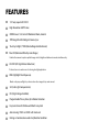
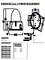
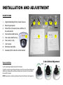
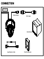
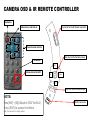
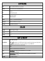
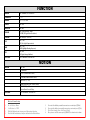
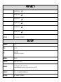
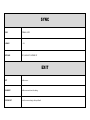
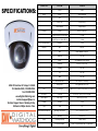
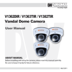
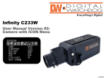
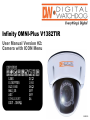
Infinity OMNI-Plus V1382TIR User Manual Version #2: Camera with ICON Menu 11192010 PRECAUTIONS Do not open or modify. Do not open the case except during maintenance and installation, for it may be dangerous and can cause damages. Do not put objects into the unit. Keep metal objects and flammable substances from entering the camera. It can cause fire, short-circuits, or other damages. Be careful when handling the unit. To prevent damages, do not drop the camera or subject it to shock or vibration. Do not install near electric or magnetic fields. Protect from humidity and dust. Protect from high temperature. Be careful when installing near the ceiling of a kitchen or a boiler room, as the temperature may rise to high levels. Cleaning To remove dirt from the case, moisten a soft cloth with a soft detergent solution and wipe. Mounting Surface The material of the mounting surface must be strong enough to support the camera. FCC COMPLIANCE This equipment has been tested and found to comply with the limits for a Class B digital device, pursuant to Part 15 of the FCC rules. These limits are designed to Provide reasonable protection against harmful interference .when the equipment is operated in a residential environment. This equipment generates, uses, and radiates radio frequency energy; and if it is not installed and used in accordance with the instruction manual, it may cause harmful interference to radio communications. WARNING: Changes or modifications are not expressly approved by the manufacture. TROUBSHOOTING Before sending your camera for repair, check the following or contact our technical specialist. No VIDEO Check the coaxial cable and make sure it is connected securely. Check the lens’ iris adjustment at the menu setup of the camera. Check the power supply and make sure the camera has the proper voltage and current. Out-of-Focus VIDEO Check the clear dome cover and the lens for dirt or fingerprints. Use a soft cloth and gently clean. Check the lens manual focal and zoom adjustment. Field test monitor is recommended. FEATURES 1/3” Sony Super HAD II CCD High Resolution 560TV Lines OMNI-Focus 2.9~8.5mm 3X Motorized Zoom, Auto Iris 70ft Range IR with Intelligent Camera Sync True Day & Night / TDN5 (Electro Magnetic Mechanism) Max-DR (Electronic Wide Dynamic Range) Enables the camera to capture perfect images in both bright and dark environments simultaneously. 3D-DNR (3D Digital Noise Reduction) Produces less noise and more color during low-light application. HME (Highlight Mask Exposure) Masks overly exposed light to produce a true video image of any environment. SLC (Side Light Compensation) DIS (Digital Image Stabilizer) Programmable Privacy Zone (6) & Motion Detection Easy Icon Driven OSD Menu with Built-In Joystick Auto Sensing 12VDC or 24VAC with Line Lock No Fog or Condensation under Any Weather Condition DIMENSION (mm) & POWER REQUIREMENT POWER REQUIREMENT: 12VDC @1A 24VAC @ .500mA Power Wire Maximum Distance Wire Gauge 24 AWG 22 AWG 20 AWG 18 AWG 16 AWG 14 AWG 12 AWG 10 AWG 12VDC 80ft 128ft 203ft 323ft 514ft 816ft 1295ft 2057ft 24VAC 323ft 513ft 815ft 1295ft 2056ft 3264ft 5183ft 8228ft COAXIAL CABLE TYPE MAXIMUM DISTANCE RG59/ U RG6/U RG11/U 750feet 1,000feet 1,500feet RS485 (Black+ & White -) INSTALLATION AND ADJUSTMENT Included with DW Vandal Camera: 1. 2. 3. 4. 5. 6. 7. 8. 9. Mounting Template User Manual One Security L-Key One Single Sided Hex Key One Double Sided Hex key Secondary BNC Cable for a Field Monitor Four (4) Screws and Four (4) Dry Wall Anchors 3 Axis Gimbal Guide IR Remote Controller Camera Installation Use the mounting template to mount the camera. Using the security L-key to loosen the four screws that secure the vandal proof dome cover, Remove the vandal proof dome cover to access the screw holes to mount the camera. NOTE: Keep the lens and the vandal proof cover free from dust or fingerprint. 6 3 4 5 7 1 2 8 9 3-Axis Gimbal Adjustment 70.0° INSTALLATION AND ADJUSTMENT INSIDE THE BOX 1. 2. 3. 4. 5. 6. 7. 8. 9. Digital Watchdog Infinity Vandal Camera Mounting template Pack of four (4) wood screws and four (4) dry wall anchors One double sided hex key 1 One single sided hex key One security L-key User manual IR Remote Controller Secondary BNC cable for a field monitor 5 Camera Installation Use the mounting template to mount the camera. Using the security L-key to loosen the four screws that secure the vandal proof dome cover, Remove the vandal proof dome cover to access the screw holes to mount the camera. NOTE: Keep the lens and the vandal proof cover free from dust or fingerprint. 4 3 2 6 9 8 7 3-Axis Gimbal Adjustment 70.0° CONNECTION DC12V / AC24V Video Output BNC Cable Main Monitor Spot Monitor Cable Field Test Monitor CAMERA OSD & IR REMOTE CONTROLLER Key Button Menu Access and Control Dip Switch for the IR Remote Controller Zoom Function Control Mini Joystick for the Menu Setup ID Buttons RIGHT Motion Alarm On &OFF UP DOWN LEFT Field Test Monitor Video Output NOTE: Press [KEY] + [ID] (Default is “001” for ID=1) Press [ENT] to access the Menu Note: The camera ID is a 3-digit number. RS485 Connector EXPOSURE LENS DC (0~100) / MANUAL / VIDEO. (DC Lens is recommended.) SHUTTER 1/160 /1/100 / FLC / 1/250 ~ 10000 / SENS-UP x2 ~ x250 BLC OFF / ON BLC (Back Light Compensation) AGC HIGH / MIDDLE / LOW / OFF AGC (Auto Gain Control) MAX-DR OFF / ON (0 ~ 20) (Electronic Wide Dynamic Range) STAR-LIGHT AUTO (x2 ~ x250) / OFF (x32 is recommended.) EXIT JUMP EXIT / SAVE&EXIT / FACTORY RESET COLOR WB MODE AWC / ATW / MANUAL / PUSH LOCK R-Y GAIN 0 ~ 100 B-Y GAIN 0 ~ 100 DAY & NIGHT AUTO / COLOR / BW / EX-CONT Day & Night Mode COLOR ---- BW : Switching from color to BW; if the number is higher, the camera will only switch during a super low light condition. BW ---- COLOR : Switching from BW to color; this number should always be lower than COLOR to BW Read Time: Time interval to switch from Color to Black-and-White COLOR B&W: (BURST:OFF/ON) When the burst is OFF will make less noise C-SUP Color Suppression :Color will be reduced at low illumination, if the C-SUP Level is higher. 0 ~ 100 (Not Available when DNR is On.) A-SUP Aperture Suppression: The sharpness of the edges will be reduced at low illumination, if A-SUP Level is higher. 0 ~ 100 (Not Available when DNR is On.) EXIT JUMP EXIT / SAVE&EXIT / FACTORY SET FUNCTION MIRROR OFF / MIRROR / V-FLIP / ROTATE SHARPNESS 0 ~ 31 GAMMA 0.05 ~ 1.00 / USER FREEZE OFF / ON NEGATIVE OFF/ ON 3D-DNR OFF / LOW / MIDDLE / HIGH 3D-DNR (3D Digital Noise Reduction) D-ZOOM OFF / ON (x1.0 ~ x32 PTZ) SLC OFF / ON SLC (Side Light Compensation) HME OFF / ON HME (Highlight Masking Exposure) DIS OFF / ON DIS (Digital Image Stabilizer) EXIT JUMP EXIT / SAVE&EXIT / FACTORY SET MOTION MOTION OFF / ON SET WINDOW ALL SET (Set the Entire Screen) ALL CLEAR (Clear the Entire Screen) SENSITIVITY (1 ~ 120) SHOW INDICATOR (OFF / ICON / TRACE) DELAY OUT (1 ~ 15) Motion Alarm Zoom-In Delay EXIT JUMP EXIT / SAVE&EXIT / FACTORY SET M o t i o n A l a r m S etu p 1. 2. 3. 4. Go to Motion Menu Set Motion to “ON” Click [Set Windows] and set your area of the motion detection Press the Left Arrow button, until you exit back to the Motion Menu 5. 6. 7. 8. Zoom out to the farthest you want the camera to zoom out and press [7](Wide) Zoom in to the farthest you want the camera to zoom in and press [8](Tele) Click [Exit Jump] then click [Save & Exit] Once you are out of the menu press [9](ON/OFF) to activate motion alarm PRIVACY MASK 1 OFF / ON MASK 2 OFF / ON MASK 3 OFF / ON MASK 4 OFF / ON MASK 5 OFF / ON MASK 6 OFF / ON EXIT JUMP EXIT / SAVE&EXIT / FACTORY SET SETUP CAMERA ID 0 ~ 255 TITLE OFF / ON DPC OFF / AUTO DPC (Dead Pixels Cancellation) MONITOR CRT / LCD LANGUAGE English, Japanese, Chinese BAUDRATE 2400 / 4800 / 9600 / 14400 / 19200 / 38400. Protocol is Pelco-D (fixed cannot be changed; hardcoded into the DSP) OMNI LENS OFF / 1 ~ 10 (for OMNI-PLUS CAMERA only) EXIT JUMP EXIT / SAVE&EXIT / FACTORY SET SYNC SYNC INTERNAL / AUTO V-PHASE 0 ~ 199 EXIT JUMP EXIT / SAVE & EXIT / FACTORY SET EXIT EXIT Exit the menu SAVE&EXIT Exit the menu and save the setting FACTORY SET Reset the menu setting to factory default SPECIFICATIONS: Camera TYPE Color / BW V1382TIR Mount Surface Device Super HAD II CCD Size 1/3" Pixels-Total 811(H) x 508 (V) Pixels-Effective 768(H) x 494 (V) System 525 line, 2:1Interlace Horizontal Frequency Internal Mode 15,734Hz Vertical Frequency Internal Mode 59.94Hz Min. Scene Illumination IR-LED on 0.0 Lux Functions BLC ON / OFF AGC HIGH / MIDDLE / LOW /OFF MAX-DR OFF / ON Mirror OFF / MIRROR / V-FLIP / ROTATE STAR-LIGHT AUTO (x2 ~ x250) / OFF 3D-DNR OFF / ON SLC OFF / ON HME OFF / ON Motion Detection OFF / ON (Area / Sensitivity) Privacy Zone 6 Programmable Zone / Size Lens Focal Length OMNI-Focus 2.9~8.5mm 3x Motorized Zoom, Auto Iris Resolution Horizontal 560 TV Lines [Color]; 580 TV Lines [BW] Video Output VBS 1.0Vp-p VBS 1.0Vp-p (75 Load) S/N Ratio S/N Ratio 50dB OSD OSD YES Environmental Conditions Operating Temperature -10℃ ~ +55℃(14℉ ~ 131℉) Humidity Less than 90% Power Requirement 12VDC / 24VAC Power Consumption 1.8 [W] / 2.4 [W] LED Off; 4.6 [W] / 4.9 [W] LED On Image Scanning 5436 W Crenshaw St. Tampa, FL 33634 Tel: 866-446-3595 / 813-888-9555 Fax: 813-888-9262 www.Digital-Watchdog.com [email protected] Technical Support Hours: Monday-Friday 8:30am to 8:00pm Eastern Time Power