1
Echelon®, LON®, LONW ORKS®, Neuron®, 3150® and the Echelon logo are trademarks of
Echelon Corporation registered in the United States and other countries.
LonMakerTM and the Lon Users logo are trademarks of Echelon Corporation.
1
Contents
1. Introduction ..........................................................................................................................2
1.1 Purpose of this manual ............................................................................................................................ 2
1.2 Terminology used in this manual.............................................................................................................. 2
2. Product Outline .....................................................................................................................3
2.1 Outline and features................................................................................................................................. 3
2.2 List of products......................................................................................................................................... 4
2.3 Function ................................................................................................................................................... 4
2.4 Specification ............................................................................................................................................. 5
3. System Design Flow ..............................................................................................................7
4. Designing the LMAP03U .........................................................................................................8
4.1 Selecting the air conditioners................................................................................................................... 8
4.2 Selecting the function............................................................................................................................. 10
4.3 Selecting the system control parts ......................................................................................................... 12
4.4 Object ..................................................................................................................................................... 14
4.5 Restrictions on system configuration ..................................................................................................... 16
5. Design and Operation of LONWORKS System ..........................................................................18
5-1 Constructing the LONWORKS network ................................................................................................. 18
5.2 Function relating to installing ................................................................................................................. 19
5.3 Operation at power recovery.................................................................................................................. 20
5.4 Response restrictions on Poll (Fetch) demand...................................................................................... 24
5.5 Operation/setting of air conditioner ........................................................................................................ 25
5.6 State monitoring ..................................................................................................................................... 27
5.7 Measurement (Analog value) ................................................................................................................. 29
5.8 Trouble/alarm monitoring ....................................................................................................................... 30
5.9 Emergency stop ..................................................................................................................................... 31
APPENDIX 1. Outline of Functions – Network Variables ..................................................................32
APPENDIX 2. Outline of Functions – Configuration Properties ..........................................................53
1
1. Introduction
1.1 Purpose of this manual
This manual provides design information and restrictions required by the system designing in constructing
the LONWORKS ® network system using LM ADAPTER. For the items not described here, please refer to the
literatures shown below.
LM ADAPTER installation work
: "Installation Manual of LM ADAPTER"
M-NET wiring and designing
: DATA BOOK of air conditioner and the like
Network variable specification
: "Network Variables Specification" of LM ADAPTER
1.2 Terminology used in this manual
This manual uses abbreviations for product names and unit classification partially. The main abbreviations
are given below. For the terminology relating to the LONWORKS, please see the Appendix of this manual.
LMAP
: LM ADAPTER
BMS
: Building management system
SC
: System controller
IC
: Indoor unit
OC
: Outdoor unit
RC
: Local remote controller
<MA remote controller (PAR-20MAU, etc.)>
<ME remote controller (PAR-F27MEA-US, etc)>
MA
: Local remote controller <MA remote controller (PAR-20MAU, etc.)>
ME
: Local remote controller <ME remote controller (PAR-F27MEA-US, etc)>
TR
: Central controller
2
2. Product Outline
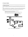
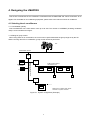
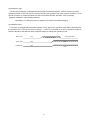
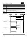
2.1 Outline and features
The LM ADAPTER is a communication interface to connect the Mitsubishi Electric made products for M-NET
use with the LONWORKS network. Only one LM ADAPTER can control and monitor indoor units up to 50
sets.
Since the LONWORKS network is an open protocol, connection with the Building management system
(BMS) and other products usable with LONWORKS can be performed easily thus allowing construction of
various systems including "Schedule operation," "Interlocked operation" and "Energy saving control".
<Features>
- Maximum 50 sets indoor units connectable with one LM ADAPTER
- Operation/monitoring with local remote controllers
- Standard Network Variables Type (SNVT) and enriched function (network variables)
- Various Configuration Properties (CP) essential for network construction
Building management
system (BMS)
LONWORKS network
LMAP
OC
Power supply unit
M-NET indoor-outdoor
transmission line
M-NET centralized control
Transmission line
System remote
controller
IC
IC
IC
ME
MA
OC:Outdoor unit
IC :Indoor unit
MA:MA remote controller
ME:ME remote controller
OC
IC
*Make sure to install the local remote
controller or system controller.
Figure 1-1. System configuration diagram (Example)
3
2.2 List of products
The air conditioners controllable with LM ADAPTER are shown below.
Model name
LMAP03U
1
Objective models for control
CITY MULTI, LOSSNAY
2.3 Function
The basic functions of LM ADAPTER are outlined as below.
Items2
Details
Emergency stop
Stopping all air conditioners. Not prohibiting local remote controller operation.
ON/OFF
Operating/monitoring ON/OFF state.
Mode
Operating/monitoring the operation mode set for air conditioners & LOSSNAYs.
SetPoint
Operating/monitoring the temperature set of air conditioners.
Fanspeed
Operating/monitoring the fan airflow rate setting.
Operating/monitoring the operation prohibit of local remote controllers.
Local remote controller prohibit
(ON/OFF, operation mode, temperature setting, batch)
Forced thermostat OFF
Operating/monitoring the forced thermostat OFF of air conditioners.
Filter sign/Run time for filter
Resetting/monitoring the integrated data of filter operation time.
Setting the local remote controller.
Local remote controller setting
(Time, temperature setting range, simplified locking, actual operation mode display, room
temperature display)
Defrosting state
Outputting the defrosting status of all air conditioners.
Failure/alarm
Outputting the failure of air conditioners, control panels and humidifiers.
LM ADAPTER
Outputting the communication error if existed between LM ADAPTER and air conditioners.
abnormal communication state
Air conditioner (charging) information
Outputting each state of the operation/thermostat/auxiliary heater of air conditioners.
(thermostat status)
Air conditioner (charging) information
Outputting the capacity code of air conditioners.
(capacity code)
Space temperature status
1
2
Outputting the outlet and inlet temperature of each air conditioner.
North America model
The applicable function differs depending on the objective models for control.
4
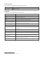
2.4 Specification
(1) Product specification
Items
1
Specification
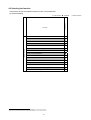
Dimension
340mm(Height) x 360mm(Width) x 59.6mm(Depth)
13 7/16(Height) x 14 3/16(Width) x 2 3/8(Depth) in
Weight
3.4 kg / 7 ½ lb
Power source
~ 208 – 230V (60Hz)
Power consumption
10 W
Data holding
Memorizing binding information, address information on air conditioners
and set values in nonvolatile memory. Input/output variables are not
held.
Environmental
Temperature
condition
Operating
- 15 to 43 ℃ / 5 to 109 °
F
Non operating
- 20 to 60 ℃ / - 4 to 140 °
F
Humidity
Installation method
30 to 95 %RH (No condensation allowed)
Mountable in horizontal or vertical direction
For vertical installation, locate in the direction of the pasted seal.
External finish
Galvanized steel plate
Alias
100 pieces
Explicit message
Not applicable yet
Neuron ID
Indicated on the seal attached to circuit board (differs by product)
Program ID
Indicated on the seal attached to circuit board (differs by product)
Neuron chip
TMPN3150(10MHz)
1 piece
Network transceiver
FTT-10A (Free topology 78kbps)
1 piece
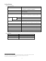
(2) Performance
Items
2 3
Specification
Mean communication capacity
2.5 input / second
Peak communication capacity
50 input / second (for 1 second)
Response capacity for poll demand
15 demand / second
1
For the detail specification of the LONWORKS network, see the data published by Echelon. "FTT-10A Free Topology Transceiver User's Guide"
2
Transmitting with an interval time exceeding the capacity hinders normal receiving. Please take a sufficient interval.
The Ack Service is recommended for your network service.
3
5
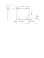
(3) External dimension
6
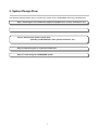
3. System Design Flow
The following indicates design flow to construct the system of the LONWORKS network by LM ADAPTER.
Step 1: Selecting the air conditioners (objective equipment for control, restrictions, etc.).
Step 3: Selecting the system control parts
(Quantity of LM ADAPTER, other system controllers, etc.).
Step 4: Determining the air conditioner addresses.
Step 5: Constructing the LONWORKS system.
7
4. Designing the LMAP03U
This section summarizes the air conditioners controllable with LM ADAPTER and various restrictions to be
applied. For the details of air conditioning equipment, please refer to the manual of each air conditioner.
4.1 Selecting the air conditioners
4.1.1 Controllable quantity
One LM ADAPTER can control indoor units up to 50 sets. The number of LOSSNAY (including ventilation
units) is to be included in this figure.
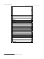
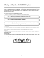
4.1.2 Range of group control
When using other SC in combination, the control can be performed within the group range set by the SC.
When not using other SC in combination, group control cannot be performed.
BMS
LONWORKS network
LMAP
OC
Power supply unit
M-NET centralize control
transmission line
System remote
controller
M-NET indoor-outdoor
transmission line
IC
IC
IC
Group1
IC
Group2
ME
ME
OC
IC
Group3
*Make sure to install a local remote
controller or system controller.
Figure 4-1. System configuration (Example)
8
4.1.3 Objective equipment for control
The following table lists the objective air conditioners for control.
Some indoor units own the plural M-NET addresses. For counting the connected numbers, refer to the table
below.
O : Controllable
x : Uncontrollable
△ : Controllable depending on connected models
Function
LMAP03U
Counting method of connected quantity
Models
○
CITY MULTI
PAC for general purpose/industrial application
K-control unit
1
Quantity of indoor unit
×
×
-
4.1.4 Connecting location
Connect LM ADAPTER to the centralized system transmission line of air conditioners.
4.1.5 Restriction on M-NET transmission wiring
As the M-NET transmission line has restrictions on its wiring length, wire materials, etc. in accordance with
the system configuration, the design should be conducted taking the transmission lines of air conditioners and
control equipment into your consideration. For detail, please refer to the manuals such as the "DATA BOOK"
of each air conditioner.
1
Unable to control/monitor even by connecting the K-transmission converter.
9
4.2 Selecting the function
The list below shows the operation/monitor function of LM ADAPTER.
(1) Operation/Setting
◎: With function ●: Individual
CITY MULTI
Function
Request All OFF (Emergency stop)
●
Request On/Off
●
Request Mode
●
SetPoint
●
Request LOSSNAY Mode
-
Operation/Setting
●
Request Fanspeed
Request Local Prohibit On/Off
Request Local Prohibit Mode
1
●
1
●
Request Local Prohibit SetPoint 1
Request Collective Operation Prohibit
●
1
Request Forced Thermostat OFF
●
Filter Sign Reset
●
Time Stamp
2
●
Request Limit Temperature Setting Range
Request Simplified Locking 2
1
2
●
2
●
●
Applicable only at using of MA remote controller (PAR-20MAA) for a local remote controller.
Applicable only at using of ME remote controller (PAR-F27MEA) for a local remote controller.
10
-: Without function
(2) Monitoring/Measuring
◎: With function ●: Individual
Emergency state
●
On/Off run state
●
Collective On/Off state
●
Mode state
●
SetPoint state
●
LOSSNAY Mode state
-
●
Fanspeed state
Local Prohibit On/Off state
Local Prohibit Mode state
Measuring/Monitoring
1
CITY MULTI
Function
1
●
1
Local Prohibit SetPoint state
●
1
Collective Local Prohibit state
●
1
●
Forced Thermostat OFF state
●
Filter Run Time
●
Space Temperature
●
Alarm state
●
Collective Alarm for Indoor Unit
●
Collective Alarm for LM ADAPTER
●
Error Code
●
Error Unit Address
●
Thermostat On/Off state_1
●
Thermostat On/Off state_2
●
Model Code
●
Defrost state
●
Applicable only at using of MA remote controller (PAR-20MAA) for a local remote controller.
11
-: Without function
4.3 Selecting the system control parts
Using the system controller (SC) together other than LM ADAPTER allows connecting operation. Some
rules to be observed for this purpose are introduced below.
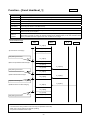
4.3.1 Master controller and slave controller
When LM ADAPTER is used together with other system controller inside a system under own control, it is
essential to set a slave SC(requiring a DIP-SW change). In this case, set it so that the control range of LM
ADAPTER is included within the control range of the system controller (air conditioner) which is to be the
master SC.
M-NET centralized control
transmission line
Mas ter SC
OC
M-NET indoor-outdoor
transmission line
System remote
controller
IC
IC
IC
Power supply unit
Slav e SC
LMAP
MA
ME
Figure 4-2. System configuration of system controller
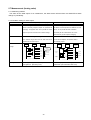
(1) In the case when the control range of the LM ADAPTER is covering that of plural system controllers, make
sure to install the Master system controller that covers the LM ADAPTER control range.
Master SC
LM ADAPTER
control range
SC1
control
range
LM ADAPTER
control range
SC2
control
range
SC1
control
range
SC2
control
range
(2) In the case when the LM ADAPTER control range is covering the control range of the system controller
partially, install the system controller so that it covers the entire control range of LM ADAPTER.
SC2
control range
SC1
control range
SC1
control range
LM ADAPTER
control range
12
LM ADAPTER
control range
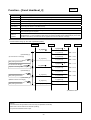
4.3.2 Local remote controller
The local remote controller includes ME remote controller (PAR-F27MEA, etc.) to be connected to the
M-NET indoor-outdoor transmission line of air conditioners and MA remote controller (PAR-20MAA, etc.) to be
connected to each indoor unit. Each remote controller provides a different function usable by LM ADAPTER
and a different system construction method.
M-NET centralized control
transmission line
Mas ter SC
OC
M-NET indoor-outdoor
transmission line
System remote
contoller
IC
IC
IC
Power supply unit
Slav e SC
LMAP
MA
ME
Figure 4-3. System configuration of local remote controller
(1) Comparison of function by local remote controllers
The usable function (network variables) by LM ADAPTER differs depending on the model of the local remote
controllers (MA remote controller/ME remote controller).
MA remote
ME remote
controller
controller
Function (NV names)
Request Local Prohibit (ON/OFF , Mode , SetPoint)
○
△
1
Local Prohibit State (ON/OFF , Mode , SetPoint)
○
△
1
Request Collective Local Prohibit
○
△
1
Collective Local Prohibit State
○
△
1
Time Stamp
×
△
2
Request Limit Temperature Setting Range
×
△
2
Request Simplified Locking
×
△
2
○ : With function
△ : Possible with limitation
×: Without function
(2) Caution on a system without using remote controller
The following problems will be incurred when the operation/monitoring is done only from the BMS
(centralized monitoring system) without using the local remote controller. Therefore, please be sure to install a
local remote controller or system controller without fail.
① Test run can not be applied to air conditioners until the BMS has started up.
② Air conditioners can not be operated or monitored when trouble is generated on the BMS and
LM ADAPTER.
③ The detail of the trouble i.e. the stopping of indoor units can not be clarified.
④ The operation/setting of the items other than that controlled by the BMS cannot be performed.
⑤ Interlocked setting of LOSSNAY and air conditioners can not be performed.
1
2
Applicable to some model of CITY MULTI air conditioners ( manufactured after January 2003 ) even when using ME remote controller.
Applicable when only using ME remote controller for the standard models except the medium temperature models.
13
4.3.3 External contact input/output
The external contact input/output function is not provided to LM ADAPTER.
4.3.4 Power supply to M-NET transmission line
The M-NET centralized system controller line should be powered. For the system using other system
controller or that with LOSSNAY only, the power supply unit for transmission line is required. In accordance
with the system configuration, the setting of LM ADAPTER and outdoor units should partially be changed.
Please conduct the setting operation by referring to the "Installation Manual" of LM ADAPTER. For the power
supply capacity of the power supply unit and the selection of the unit, please refer to the manuals (like DATA
BOOK) of each air conditioner.
Installation of power supply unit
Individual
With SC
Not required
Required
LMAP02-E
LMAP03U
4.4 Object
4.4.1 Network variables and objects
The network variables provided allows the LA ADAPTER to operate/monitor plural equipment (indoor unit,
LOSSNAY, etc.) The functional profile (object) represents the network variables collected for each objective
equipment to be controlled. Here the objects and network variables are outlined, and the relationship with air
conditioners is explained. For the detail of each object and the specification of the network variables, please
refer to the "Network Variables Specification" of each product.
(1) Object configuration of LM ADAPTER
Node
Object
For node object
Indoor [0]
Indoor [50]
Indoor [1]
For collective variables
and configuration property
14
For indoor unit
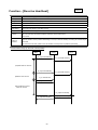
(2) Object and equipment address
The object for indoor units is individually related with the objective equipment for control. The object (Indoor
[1] ~ Indoor [50]) corresponds to the indoor unit (LOSSNAY, ventilation unit, Mr. SLIM) with the M-NET
address of 01 ~ 50 being set to each equipment.
Outdoor unit
051
IC
001
M-NET centralized
control transmission line
IC
002
IC
003
M-NET Indoor-outdoor
transmission line
Indoor [1]
Indoor [2]
Legend
OC:Outdoor unit
IC:Indoor unit
Indoor [3]
IC
05
M-NET
address
Object of LM ADAPTER
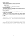
4.4.2 Network variables and air conditioner address
LM ADAPTER owns the network variables for each air conditioner. The network variables include
set/monitor of an air conditioner individually and to set/monitor of all air conditioners collectively.
Please set so that the M-NET address of the objective air conditioner for control will agree to the name of the
variable.
Outdoor unit
051
IC
001
IC
002
M-NET centralized
control transmission line
IC
003
M-NET Indoor-outdoor
transmission line
Request On/Off
On/Off run state
SetPoint
SetPoint state
:
:
:
Indoor [1]
:nviOnOff_001
:nvoOnOff_001
:nviSetP_001
:nvoSetP_001
:
:
:
For No.1 indoor unit
Network variable name → Function name + M-NET address (3-digit display)
Relationship between M-NET address and Network variables
15
4.5 Restrictions on system configuration
The restrictions in constructing the system by LM ADAPTER are outlined here.
4.5.1 Restrictions by system configuration
(1) Group control
In the case when the group setting of indoor units are carried out by the local remote controller or system
controller, the operation from the BMS is performed as follows.
Group setting
Operation
Monitoring
every unit
every unit
No setting
(individual)
Setting by the local
remote controller
every unit
Required to issue a same command to all
every unit
indoor units
Setting by the system
controller
Principal
1
unit in the same group
When using “Forced Thermostat OFF” is
every unit
required to request into indoor units individual
4.5.2 Restrictions by control items
(1) Operation prohibit
① When using together the system controller that can set to prohibit the local remote controller operation,
make the controller for setting of operation prohibit one unit, either LM ADAPTER (BMS) or the system
controller.
② Operation prohibit can not be applied to other system controllers by LM ADAPTER (from BMS)
③ Although air conditioners can not be operated by the local remote controller of which operation is being prohibited,
they can be operated by LM ADAPTER (BMS) or other system controllers.
1
At the unit of lowest address in the same group
16
(2) Emergency stop
The emergency stopping of LM ADAPTER stops all air conditioners together, however it does not set the
operation prohibit of the local remote controller allowing the operation from other system controller or local
remote controller. To prohibit operation from the local remote controller, therefore, set it by entering
[Request Collective Local Prohibit] (collective).
*Operating to run during emergency stopping only results in immediate stopping.
(3) Operation mode
In the case of cooling/heating selectable models of CITY MULTI, the operation mode will be determined by
the principle of the "Priority for former pressing."
Under the circumstance, a same command should be
issued to all indoor units within a same refrigerant system to change the operation mode.
Indoor unit 1
Cool
Indoor unit 2
Cool
Outdoor unit
Heat (Inoperable)
Cool ( Inoperable)
Heat
Cool
Heat
17
5. Design and Operation of LONWORKS System
This section introduces the mechanism, function and operating method of LM ADAPTER in configuring the
system of LONWORKS network by LM ADAPTER. As the operating method shown here represents just one
of the examples, you are kindly requested to carry out your designing to meet the system configuration or
operation in the actual system.
5-1 Constructing the LONWORKS network
The flow of installation procedure for LONWORKS network is shown below.
Step 1: Addressing (to determine the address of each node)
Step 2: Binding (to connect network variables)
Step 3: Configuration (for optimum service of each connection, adjustment of
re-transmission frequency and interval)
(1) Addressing
An address is assigned to each node (equipment applicable to LONWORKS) on the LONWORKS network.
Set this address by using the install tool. Setting by using LM ADAPTER is not necessary.
(2) Binding
The network variables between each node should be related with the exclusive tool like LonMaker for
Windows ® or the like.
(3) Configuration
For the configuration property of LM ADAPTER, the initial value was set at factory shipment. The set value
may be changed depending on the configuration or operation of the network.
Node Address = 1
Node Address = 2
BMS
Indoor [1]
Binding of network variables
18
5.2 Function relating to installing
(1) Service pin (Service switch)
The service pin is used at the installation of LONWORKS network.
Pressing the service pin sends out the service pin-message (control message including Neuron ID and
Program ID) to the network.
(2) Service LED
The service ID indicates the present state of the product.
In the case of LM ADAPTER under the shipment state (Non-configured state), the service LED is blinking.
(3) WINK
Upon receipt of the WINK message from the LONWORKS network, LM ADAPTER blinks the maintenance
LED 001 for about 10 seconds.
(4) Commission
After completing the binding, the set detail is reflected on the node. Doing this way allows communication
between the nodes on the LONWORKS network.
(5) XIF
To design the LONWORKS network, the configuration information of each node, interface (network
variables), etc. are required. When the product is already in your hand, such information can be obtained from
the LONWORKS network. Without the product, however, you may get it from XIF (eXternal Interface File)
locating the interface information of the product.
19
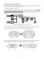
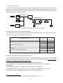
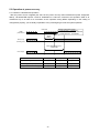
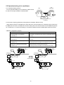
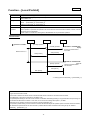
5.3 Operation at power recovery
5.3.1 Outline of LM ADAPTER operation
After the power source is applied (the same as the power recovery after instantaneous power stop/power
failure), LM ADAPTER requires a time for initialization to collect the connection and operation state of air
conditioners up to 50 sets to be controlled. As the operation timing differs depending on the setting of
configuration property, you are kindly requested to carry out designing to meet the system operation.
Power ON
LMAP
power source
Communication
Timing
(nciSet_1)
Relating configuration property
- Send Start Time( nciStartOutTm)
- Send Heartbeat Start Time( nciStartHrtBt)
- Initialize Start Time( nciInitStartTm)
Neuron chip
operating state
Send Heartbeat Start Time
(nciStartHrtBt)
Event output
(A)
(B)
(C)
(A)
(B)
(C)
Operation/setting from BMS
Not applicable
Applicable
Applicable
Monitoring by Poll (Fetch) from BMS
Not applicable
Applicable
Applicable
Output from LM-AP at changing
Not applicable
Not applicable
Applicable
20
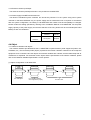
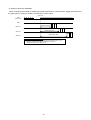
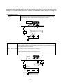
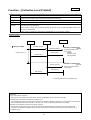
5.3.2 Setting relating to operation after power recovery
(1) Setting of Neuron Chip communication start time
The communication start timing of NC can be set through “Communication Timing 【nciSet_1】”.
① "initialize"
Upon completion of the connection between LM ADAPTER and air conditioner, NCstartsoperation. Up to
this time, NC will not reply (even without returning of Ack).
This operation is specifically used to acquire the state of air conditioners by Poll (Fetch)demand.
② "setting time"
Synchronized with the shortest time among the set times of the configuration property below, NC starts
operation. Up to this time, NC will not reply (even without returning of Ack).
This operation is specially used to acquire the state of air conditioners by event (at changing) output.
- Send Start Time 【nciStartOutTm】
- Send Heartbeat Start Time 【nciStartHrtBt】
- Initialize Start Time 【nciInitStartTm】
Power ON
LMAP power source
NC operation
[ initialize ]
Related configuration property
- Send Start Time ( nciStartOutTm )
- Send Heartbeat Start Time( nciStartHrtBt)
- Initialize Start Time( nciInitStartTm)
Set time
[ setting time ]
Completed initialization
between LM ADAPTER
and air conditioner
(2) Setting of start time relating to event output
The start timing of event output after power recovery can be set by the configuration property shown in the
table below.
Items
Set detail and operation
Send Start Time
The timing to start output at changing is set.
【nciStartOutTm】
Up to the time passing the set time after power recovery, LM ADAPTER does not
output the variables even when the status of the air conditioner changes. During this
time, the air conditioner can be operated/set.
Send Heartbeat Start Time
The timing to start the automatic updating (periodical status notice) from LM
【nciStartHrtBt】
ADAPTER is set.
Initialize Start Time
The timing to start the initial output is set.
【nciInitStartTm】
To match the image of the operation information on air conditioners held by BMS and
that of the actual operation status, LM ADAPTER automatically outputs the status of
the air conditioners after power recovery.
21
(3) Setting to match images
1
The state of an air conditioner before power failure and after power recovery may differ sometimes . In
such case, the operation state of the air conditioner held by the BMS differs from the actual operation state of
the air conditioner. In order to match the image after power recovery, LM ADAPTER can be set enabling the
initial output to match the image at a time when a certain time has elapsed after power recovery.
∇Relating configuration property
Items
Set detail and operation
Initialize Start Time
Explained before
【nciInitStartTm】
Initialize Send Time_1
The transmission interval of each air conditioner is set respectively.
【nciInitOutTm_1】
The variable firstly output by each air conditioner (operation state output) keeps the set
interval for output.
Initialize Send Time_2
The transmission interval of each variable is set respectively.
【nciInitOutTm_2】
Each variable of each air conditioner is output keeping this set interval.
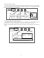
① Outline of operation
When “Initialize Start Time 【nciInitStartTm】” has passed, the state variable of air conditioners will be output
from No.1 unit in order. The transmission interval of each variable will be that being set by the configuration
property. When the initial output time per each unit exceeds “Initialize Send Time_1【nciInitOutTm_1】”, the
variable of the next indoor unit will be output after completing the output of the variable of the indoor unit
immediately before.
Power ON
LMAP
power source
State of
No.1 unit
State of
No.2 unit
Start of
No.3 unit
BMS
LMAP
Initialize Start Time
Initialize Send
Time_1
Initialize Send
Time_1
Output image in a unit of air
conditioner (Status of No.2 unit)
Initizalize
Initizalize
Initizalize
Send Time_2 Send Time_2 Send Time_2
Run
Cool
25℃
Low
Standard of set time
Initialize Send Time_1(Sec) = Initialize Send Time_2(Sec)×N
* N value (To be determined by a number of the objective variables)
N = 12
1
Through the setting of air conditioners, the operation after power recovery ( Power ON/OFF, / Automatic recover / Normal <Stop> ) can be set.
22
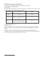
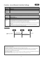
② Setting for plural unit installation
When conducting initial output by installing plural LM ADAPTERs on a same system, stagger the start time of
the initial output in setting to avoid the concentration of each output.
Power ON
LMAP
power source
BMS
Initialize Start Time
LMAP_001
Initialize Start Time
LMAP_002
Initialize Start Time
LMAP_003
Standard of set time (for LMAP_002)
Initialize Start Time(LMAP_002) = Initialize Start Time(LMAP_001) + Ti ×m
Maximum control address value of LMAP_001:m(1 to 50)
Initialize Send Time_2 of LMAP_001:Ti
23
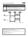
5.4 Response restrictions on Poll (Fetch) demand
Upon receipt of Poll (Fetch) demand from the BMS, LM ADAPTER responses with the latest value of the
corresponding variable.
As the operation status being held will be responded at power shutdown due to air conditioner inspection or
communication error caused by the disconnection of M-NET transmission line, the error cannot be judged by
the BMS.
When the present data being held is uncertain as is in such case, LM ADAPTER can be set so that error
generation can be judged easily by suppressing the response against Poll (Fetch) demand.
①Suppressing the response of unconnected indoor units.
②Suppressing the response of indoor units unable to communicate.
This setting is to follow the configuration property below.
Effective PollFetch【nciPollFetch】
BMS
Event driben system
LM
ADAPTER
Monitor
transmission
Indoor unit
Monitor
transmission
Monitor demand
Poll (Fetch)
system
Monitor response
Responding with
holding latest state
Monitor demand
Communication
error
Suppressing
Poll response
24
Status
change
5.5 Operation/setting of air conditioner
5.5.1 Operation/setting method
LM
ADAPTER
BMS
For the operation/setting of air conditioners, please renew
Indoor [1]
the value of the input variable of LM ADAPTER.
nvi
nvo
nvi1
nvi2
nvo1
Renewal of input
variable
Operating/setting method of air
conditioners
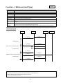
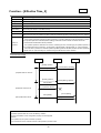
5.5.2 Function requiring periodical renewal (Receive Heartbeat, Effective Time)
When setting cannot be cancelled by the local side at the communication error caused by some reason from
the BMS side, a function is available to cancel the setting when the communication from the BMS side pauses
for a certain time. To continue the setting, it is required to update the input variable again within the set time.
∇Relating configuration property
Items
Set detail and operation
Receive Heartbeat_1 (Local Prohibit)
The setting is cancelled when the set time is passed after previous
【nciRcvHrtBt_1】
receiving.
Receive Heartbeat_2 (Forced Thermostat OFF)
The setting is cancelled when the set time is passed after previous
【nciRcvHrtBt_2】
receiving.
Effective Time_1 (Emergency Stop)
Effective request is continued over the set time.
【nciEffectTm_1】
The setting cannot be cancelled until the effective time is over.
Effective Time_2 (Collective Local Prohibit)
Effective request is continued over the set time.
【nciEffectTm_2】
The setting cannot be cancelled until the effective time is over.
Building
Management
system
Error
occurred
LONWORKS network
LONWORKS network
LMAP
Building
Management
system
Error
continues
Continue operation
prohibit
LMAP
Set time passed
OC
OC
Operation prohibit
IC
Cancel operation
prohibit
Operation permit
IC
IC
IC
IC
MA
Enable to
change setting
OFF
ON
MA
Disable to
change setting
25
IC
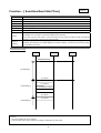
5.5.3 Function allowing operating/setting at local side
When using a remote controller together to operate air conditioners locally by user, the same function can be
operated/set at both the master system side and the local side. In this case, the "Priority is given to the later
pressing" is a principle. Please carry out to configure the LONWORKS system taking the following into
consideration.
(1) Disagreement of state
Problem
Disagreement of state may occasionally be detected when setting is changed by the local
side including the local remote controller after operating/setting of the BMS.
Measure taken by BMS side
Avoid detecting for the disagreement of the state.
BMS
Reques t:[Stop]
State:[Stop]
State
dis agreed
LONWORKS network
[Run] s tate
LMAP
Af ter operated f or [Stop] from Building
manage ment s y s tem, [Run] is reques ted
f rom loc al s ide.
OC
IC
IC
IC
[Run] reques t
MA
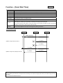
(2) Periodical transmission from master system
Problem
When receiving run request from equipment (like PLC) with the function of periodical transmission
(Send Heartbeat), the setting of the local side like remote controllers may not be reflected (or seems
to be not reflected) on the air conditioners.
Measure taken by BMS
Try to transmit (renew) a request only at a time of changing.
side
<Example actions>
- Make the periodical transmission (Send Heartbeat) invalid.
- Fetch it once by the BMS, and renew the variable of LM ADAPTER.
BMS
Interloc ked
w ith lighting
LONWORKS network
PLC
LMAP
Trans mits
periodic ally
Lighting
OFF
OC
[Stop] reques t
Stop
↓↑
Run
IC
IC
[Run] reques t
MA
[Run]s but [Stop]s s oon
26
IC
5.6 State monitoring
5.6.1 State monitoring method
The method to monitor the operation state of air conditioners from the BMS via LM ADAPTER can roughly
be classified into two systems, namely (1) Event driven system and (2) Polling system. The configuration
property for setting differs depending on the systems.
Event driven system
Polling system
Operation
State is automatically output from LM ADAPTER at the
Regardless of air conditioner state changes, the
outline
change of air conditioner status (event generation).
variable is directly acquired through polling or
fetching from the BMS at any time.
State change
At state change of air conditioner
At Poll (Fetch) demand
Each variable of both BMS and LM ADAPTER should
Polling cycle is determined taking the following into
be bound.
consideration.
output timing
Condition
①Communication traffic of whole LONWORKS
network
②Response performance of LM ADAPTER
Communication
image
BMS
Air
condi tioner
LM-AP
BMS
Poll demand
Stat e: st op
Air
condi tioner
LM-AP
Stat e: st op
Stop
Stop
Poll
cycle
stop
stop
Poll demand
Stat e: run
Stat e: run
Run
Poll
cycle
run
Poll demand
Poll
cycle
Relating nci
stop
run
nciStartOutTm【Send Start Time】
nciPollFetch【Effective PollFetch】
nciStartHrtBt【Send Heartbeat Start Time】
nciOffline【Effective Offline Mode】
nciMinOutTm【Minimum Send Time】
nciSet_1【Comminication Timing】
nciSndHrtBt_1【Send Heartbeat_1】
nciSndHrtBt_2【Send Heartbeat_2】
nciInitStartTm【Initialize Start Time】
nciInitOutTm_1【Initialize Send Time_1】
nciInitOutTm_2【Initialize Send Time_2】
nciSet_1【Communication Timing】
27
Run
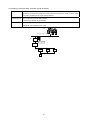
5.6.2 Setting of periodical state notification (Send Heartbeat)
Purpose
In the case of the event driven system, there is no chance to renew the state until facing the next event
generation if an unexpected omitting was incurred carelessly. During this time, the air conditioner status
being held by the BMS and that of the actual are different.
Countermeasure
Set to conduct the periodical state notification
(Transmission heartbeat: Send Heartbeat).
Setting nci
nciSndHrtBt_1【Send Heartbeat_1】
nciStartHrtBt 【Send Heartbeat Start Time】
BMS
Po ll res pons e:[Run] s tate
LONWORKS network
Run
LMAP
Trans mits
periodic ally
OC
Run
IC
IC
MA
28
IC
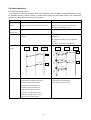
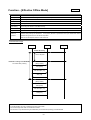
5.7 Measurement (Analog value)
5.7.1 Measuring method
The same as the state output of air conditioners, the state will be informed from LM ADAPTER at state
change or periodically.
5.7.2 Condition setting for state output
Condition setting of output at changing
Purpose
Setting of periodic state notification
As the analog value such as the room temperature
The variation range of the room temperature
varies continually, frequent outputs are presented at
decreases as the temperature is stabilized. For this
changing. To suppress this, set to provide the event
reason, set to provide the state notification
output only at the occurrence of a certain change.
periodically as the measurement can not be
performed only by the output at changing.
Countermeasure
Communication
Set the variation range of analog value.
Set the transmission interval.
The variation range below the set value will not be
As the set time elapsed, the present value is
applied with the event output.
automatically output.
BMS
LM-AP
Air
c ondit ioner
Air
c onditioner
LM -A P
BMS
image
2 2 .5 ℃
2 2 .5 ℃
pe riodic al m on itorin g
in te rval
2 2 .9 ℃
+ 1 .1 ℃
2 3 .6 ℃
22.6℃
22.7℃
10 m inut es
10 m inut es
2 3 .1 ℃
2 2 .4 ℃
22.5℃
0.2℃
2 3 .6 ℃
2 3 .4 ℃
- 1 .2 ℃
22.5℃
Event dri ve n
out put
Heartb eat
out put
2 2 .2 ℃
22.6℃
22.6℃
0.1℃
10 m inut es
2 2 .4 ℃
22.7℃
Heartb eat
out put
22.4℃
22.4℃
22.2℃
In c ase o f variatio n ran ge = 1 0 ℃
In c ase o f variatio n ran ge = 1 .0 ℃
Setting nci
nciAnalogWidth 【Spacetemp Width】
nciSndHrtBt_2 【Send Heartbeat_2】
nciAnlgMonTm 【Monitoring Time)
nciStartHrtBt 【Send Heartbeat Start Time】
29
10 minu tes
10 minu tes
10 minu tes
5.8 Trouble/alarm monitoring
BMS
The trouble/alarm that can be monitored with LM
⑤
ADAPTER can mainly be classified as follows.
(Note: It differs depending on the types of LM ADAPTER)
① Trouble of equipment such as air conditioners and
LONWORKS network
④
LMAP
remote controllers
M-N ET c entraliz ed c ontrol
s ys tem trans mis s ion line
② Network fault of M-NET
②
③ Alarm due to improper air conditioning
①、③
OC
④ Trouble of LM ADAPTER
M-NET indoor-outdoor
trans mis s ion line
⑤ Fault of LON network
IC
IC
IC
MA
Section in trouble
Symptom
Monitoring method
①③
Trouble of relating equipment such as air
Air conditioning equipment
conditioner/remote controller
② M-NET communication
1) Network variable (Error)
1) None
Unable to communicate between
1) Network variable (Error)
1) None
LM ADAPTER and objective equipment
2) Presence of Poll response
2) nciPollFetch
for control
④ LM-AP
(Effective PollFetch)
Trouble of LM ADAPTER itself
1) Node object
1) & 2) nciSet_1
2) Presence of response
(Communication
(including Ack)
⑤ LON communication
Relating nci
Timing)
Unable to perform the communication of
1) Node object
1) & 2) nciSet_1
LONWORKS network
2) Presence of response
(Communication
(including Ack)
Timing)
5.8.1 Trouble/alarm monitoring by network variables
(1) Trouble and alarm of air conditioner - - - ①,③
Air conditioning equipment in trouble will be informed to the BMS by the network variables via LM ADAPTER.
In case when the local remote controller or system controller is installed, the detail of the trouble will be
displayed.
Detecting method of trouble
- Trouble of indoor unit : Error output from individual indoor unit
- Trouble of outdoor unit : Error output from all indoor units within a same refrigerant system
(2) Communication fault of M-NET (including power failure) - - - ②
When the communication (M-NET) between LM ADAPTER and air conditioner is disabled, LM ADAPTER
monitors the communication with the air conditioner for a certain time, and informs you about a
communication error if abnormality is detected.
Detecting method of M-NET communication error
- Network variables (collective for all indoor units) exclusive for communication error
- Response to Polling (by “Effective PollFetch 【nciPollFetch】”)
30
(3) Resetting of trouble/alarm
The resetting method differs depending on the equipment generating trouble/alarm.
Trouble of indoor unit
Switches over the indoor unit in trouble from [Run] to [Stop].
Trouble of outdoor unit
Switchovers all indoor units in the refrigerant system from [Run] to [Stop].
5.8.2 Health check of LM ADAPTER - - - ④,⑤
Several factors can be considered as the cause to disable the communication of the master system with LM
ADAPTER. Depending on the function of the BMS or the system configuration, conduct health check (to judge
the life) by combining each detecting method.
(1) Detection by Node Object
The Node Object is an exclusive variable to conduct health check (to judge the life) on LM ADAPTER. This is
effective when the application of LM ADAPTER is crashed under the condition allowing LON communication,
or to detect the recovery timing of power failure.
The node object uses the input variable 【nviRequest】 and output variable 【nvoStatus】 in a pair. The
output variable returns the value corresponding to the requested value when only the input variable is
renewed. The response can be performed if the application is working regardless of the status of the local
side (M-NET).
(2) Detection by effectuation of communication
When Ackd is used as the communication service of LON communication, the fault of LON communication
can be monitored by the presence of Ack.
However for the generating spot of the communication error, it is
required to judge comprehensively taking the communication status of other node into consideration.
5.9 Emergency stop
In the case when air conditioners are stopped (emergency stop) collectively, it is considered that the
communication with the master system may not be performed after stopping. For this reason, the present
status will be maintained until “Effective Time_1【nciEffectTm_1】” has passed once emergency stop was
received. Even after releasing the emergency stop, the air conditioner will continue to stop unless receiving
the run request.
31
APPENDIX 1. Outline of Functions – Network Variables
- Models
LMAP03U
- Functions
「ON/OFF」
「Mode」
「Thermostat ON/OFF state」
「Filter Sign Reset / Run Time for Filter」
「LOSSNAY Mode」
「Error state」
「Collective Alarm」
「Collective ON/OFF」
「Local Prohibit」
「Collective Local Prohibit」
「Local Remote Controller Setting」
「Space Temperature」
「Set Point」
「Fan Speed」
「Forced Thermostat OFF」
「Emergency Stop」
「Model Code」
「Collective Alarm for LM ADAPTER」
「Defrost state」
「Group Number」
32
LMAP03U
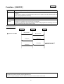
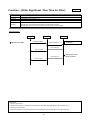
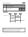
Function - [ ON/OFF ]
Function
[Request On/Off] [On/Off run state]
Description
The run/stop operation and state of indoor units or ventilation units (individual operation without interlocking) are
monitored.
In the case of the ventilation unit interlocked with the indoor unit, the operation will run/stop interlocking with the
indoor unit being registered for interlocking.
Using NV
【nviOnOff_n】【nvoOnOff_n】
Control unit
Indoor unit
Outline of
operation
"Indoor unit" will run/stop for each unit individually.
"Ventilation unit (individual)" will run/stop for each unit individually.
"Ventilation unit (interlocked)" will run/stop interlocking with the unit being registered for interlocking. There is no
need to control the operation and to monitor the state.
Communication Image
BMS
① Operation from BMS
IC
LM-AP
[Run] operation
[Run] operation
state [Run]
state [Run]
state [Stop]
state [Stop]
Restrictions
- Operation control during emergency stopping (LMAP03U only)
During the emergency stopping in valid, the operation control by the LonWorks network will be invalid.
33
② Operation from local
remote controller
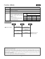
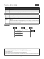
Function - [Mode]
LMAP03U
Function
[Request Mode] [Mode state]
Description
The operation mode control and state of the indoor unit are monitored.
Using NV
【nviMode_n】 【nvoMode_n】
Control unit
Indoor unit
Outline of
operation
"Cooling only unit", "Heat Pump (Y unit)"
Within a same refrigerant system, the mixed
operation of cooling and heating can not be
performed. "Priority is given to the former
pressing."
"Heat Pump (R2 unit)"
Within a same refrigerant system, cooling
and heating operation can be mixed. "Priority
is given to the later pressing."
Within a same refrigerant system, mode
operation can be mixed.
Cooling only unit
Y unit
R2 unit
Auto
--
--
All
Cool/Dry
Fan
Fan
All
Heat
--
Fan
All
Fan
Cool
Cool/Heat
All
Communication Image
BMS
IC
LM-AP
[Cool] operation
[Cool] operation
① Operation from BMS
state [Cool]
state [Cool]
state [Heat]
state [Heat]
② Operation from local
remote controller
Restrictions
- How to determine the operation mode
In the case of CITY MULTI air conditioners (models exclusive for cooling and that for cooling/heating selectable), priority is given to
the operation mode (Cooling-Dry/Heating) formerly adapted to the indoor unit within a same refrigerant system. ("Priority is given to
the former pressing.") To change the operation mode, therefore, change the operation mode of all indoor units within a same
refrigerant system simultaneously.
For the models of cooling/heating simultaneous operation, the indoor unit operating for cooling (drying) and that for heating can be
mixed in a same refrigerant system. ("Priority is given to the later pressing.")
34
LMAP03U
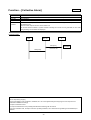
Function – [Thermostat ON/OFF state]
Function
[Thermo On/Off state_1] [Thermo On/Off_2]
Description
Monitoring the thermostat state of indoor units, run/stop state, and the state of auxiliary heater for heating.
Using NV
LMAP02-E:【nvoThermo_n】
LMAP03U:【nvoThermoSt_n】【nvoThermo_n】
Control unit
Indoor unit
Outline of
operation
The thermostat status of each indoor unit is monitored. In the case of CITY MULTI, the compressor of the
outdoor unit turns off if the thermostat of all indoor units within a same refrigerant system turn off. (It depends on
the operating condition.)
*While the thermostat is turned off forcibly, the thermostat OFF will be output. (LMAP03U only)
Communication Image
BMS
IC
LM-AP
state [Thermostat ON]
state [Thermostat ON]
state [Thermostat OFF]
state [Thermostat OFF]
35
Thermostat [ON]
→ Thermostat [OFF]
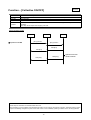
Function – [Filter Sign Reset / Run Time for Filter]
LMAP03U
Function
[Filter Sign Reset] [Run Time for Filter]
Description
Monitoring the integrated operation time of the filter. Resetting the filter sign information also.
Using NV
【nviFiltReset_n】 【nvoOnTime_n】
Control unit
Indoor unit
Outline of
operation
The filter sign resetting clears the filter sign and the filter operating integrated time.
The filter sign of the local remote controller or the like will also be reset.
The filter sign can be reset with the local remote controller or system controller.
Communication
BMS
① Operation from BMS
IC
LM-AP
[Reset] operation
[Reset] operation
Resetting the run time
of the filter
Run Time [0h]
Run Time [0h]
Run Time [0h]
② Operation from local
remote controller
Run Time [0h]
Restrictions
- The Run Time for filter.
The filter cleaning period cumulative time and maximum value differ with model (Indoor unit, ventilation, etc...).
- Continuous reset operation
When reset operation is continuously carried out by local remote control or BMS, Run Time is reset each time.
36
LMAP03U
Function – [LOSSNAY Mode]
Function
[Request LOSSNAY Mode] [LOSSNAY Mode State]
Description
Switching over and monitoring the operation and state of the ventilation unit individually operated (not
interlocked with indoor unit).
Using NV
【nviLCMode_n】 【nvoLCMode_n】
Control unit
Indoor unit
Outline of
operation
The operation mode (LOSSNAY ventilation/bypass ventilation/automatic) is selected for each ventilation unit.
However, the ventilation unit that used the LOSSNAY adapter can not be changed over to the automatic mode.
The operation mode of the ventilation unit interlocked with indoor unit is determined by the operating condition of
the indoor unit.
Communication Image
BMS
① Operation from BMS
Ventilation
LM-AP
[LOSSNAY ventilation]
operation
state
[LOSSNAY ventilation]
state
[Bypass ventilation]
[LOSSNAY ventilation]
operation
state
[LOSSNAY ventilation]
state
[Bypass ventilation]
② Operation from local
remote controller
Restrictions
-The operation mode of the ventilation unit interlocked with indoor unit can not be changed over.
-Determining measure of operation mode of ventilation unit interlocked with indoor unit
- Operation from the Building management system, system controller, and remote controller is disabled. It is fixed to the automatic
mode.
However, the ventilation unit that the LOSSNAY adapter, operation mode is fixed to the LOSSNAY ventilation mode.
37
LMAP03U
Function – [Error state]
Function
[Alarm State]
Description
Monitoring the error of the indoor unit or ventilation unit if any.
Using NV
【nvoAlarm_n】
Control unit
Indoor unit
Outline of
operation
The error of the indoor unit and ventilation unit if any is output for each unit.
The error of the outdoor unit if any is output by all indoor units within a same refrigerant system.
Function
[Error Code] [Error Address]
Description
Outputting the error detail (error code, generating source address) of the indoor unit or ventilation unit.
Using NV
【nvoErrCode_n】 【nvoErrAdrs_n】
Control unit
Indoor unit
Outline of
operation
For the error of the indoor unit and ventilation unit, the error code and generating source address are output for
each unit.
For the error of the outdoor unit, the error code and generating source address of the outdoor unit are output
from all indoor units within a same refrigerant system.
On the local remote controller or system controller controlling the unit generating an error, the error code and
generating source address are displayed.
Communication
BMS
IC
LM-AP
state [Error]
state [Alarm]
Error
occurred
Error Code [xxxx]
Error Address [xxx]
Restrictions
- Error output during stopping (All of the alarm, error code and error generating source)
Under the stopping of air conditioner, ventilation unit, etc., error output from LM ADAPTER is disabled.
- Output of maintenance error
The output of maintenance error (including intermittent fault checking) will not be done.
- For some ventilation units, the error (including all alarms, error codes and error generating source addresses) is disabled to output.
38
Function – [Collective Alarm]
LMAP03U
Function
[Collective Alarm for Indoor Unit]
Description
Monitoring the possible error of all units controlled by LM ADAPTER collectively.
Using NV
【nvoAllAlarm】
Control unit
All of indoor units controlled by LM ADAPTER
Outline of
operation
The error will be output even if 1 set of indoor units or ventilation units being controlled by LM ADAPTER
generates an error.
The error will be output at the error of the outdoor unit.
On the local remote controller or system controller controlling the unit with an error generated, the error code
and generating source address are displayed.
Communication
BMS
IC
LM-AP
state [Error]
Error
occurred
from error unit
state [Alarm]
Restrictions
- Error output during stopping
As the error judgment of air conditioners, LOSSNAY, etc. can not be applied during their stopping; the error output from LM
ADAPTER is disabled accordingly.
- Output of maintenance error
The output of maintenance error (including intermittent fault checking) will not be done.
- For some ventilation units, the output of the error (including all alarms, error codes and error generating source addresses) is
disabled.
39
LMAP03U
Function – [Collective ON/OFF]
Function
[Collective On/Off State]
Description
Monitoring the operation status of all units controlled by LM ADAPTER collectively.
Using NV
【nvoAllOnOff】
Control unit
All of indoor units controlled by LM ADAPTER
Outline of
operation
The "Run" will be output even if 1 set of indoor units or ventilation units being controlled by LM ADAPTER is
operating.
The "Stop" will be output at the stopping of all units.
Communication Image
BMS
① Operation from BMS
IC
LM-AP
[Run] operation
[Run] operation
state [Run]
state [Run]
state [Stop]
② Operation from local
remote controller
state [Stop]
Restrictions
- State output of ventilation unit interlocked with indoor unit
When operating only the ventilation unit interlocked with indoor unit by using the local remote controller, "Collective stopping" will be
output to the Building management system unless other indoor unit or individually operating ventilation unit is not being operated.
40
LMAP03U
Function – [Local Prohibit]
Function
[Request Local Prohibit] [Local Prohibit State]
Description
Monitoring and setting the prohibit/permit of operation of the remote controller to be connected with indoors unit
and ventilation unit.
Using NV
ON/OFF: 【nviProOnOff_n】 【nvoProOnOff_n】
Mode : 【nviProMode_n】 【nvoProMode_n】
SetPoint: 【nviProSetP_n】 【nvoProSetP_n】
Control unit
Indoor unit
Outline of
operation
Setting the prohibit/permit of each operation for each unit.
When operation is prohibited, the operation can not be done from the local remote controller, however, it can be
carried out from LM ADAPTER.
If other system controllers are used together, LM ADAPTER can not prohibit their operation.
Communication
BMS
① Operation from BMS
IC
LM-AP
[Prohibit] operation
[Prohibit] operation
Effective Time(*1)
“CENTRALLY CONTROLLED”
display
Remote controller buttons
are locked.
state [Prohibit]
state [Prohibit]
[Permit] operation
“CENTRALLY CONTROLLED”
goes off
Remote controller buttons
are unlocked.
state [Permit]
state [Permit]
*1: Setting by Receive Heartbeat_1 【nciRcvHrtBt_1】
Restrictions
- Types of local remote controller
This function is effective to use MA remote controller and ME remote controller for the local remote controller.
- Prohibit/permit of local remote controller for ventilation units
The prohibit/permit setting for the local remote controller of LOSSNAY individually operating is only possible when OA processing unit
is controlled with MA remote controller. In this case, turn on the function setting switch (SW1-1) of LMAP.
- Effective time of operation prohibit for local remote controller (LMAP03U only)
The operation prohibit setting of the local remote controller will automatically be the operation permit of the local remote controller, if
the effective time passes without set value renewal or poll/fetch demand within the effective time being set by the “Receive
Heartbeat_1 【nciRevHrtBT_1】”.
41
LMAP03U
Function – [Collective Local Prohibit]
Function
[Request Collective Local Prohibit] [Collective Local Prohibit state]
Description
Setting and monitoring the operation for prohibit/permit of all local remote controllers to be connected with the
indoor units and ventilation units individually operated (without interlocking).
Using NV
【nviAllPro】 【nvoAllPro】
Control unit
All of local remote controllers
Outline of
operation
The operation of all local remote controllers to be connected with indoor units and ventilation units is set
collectively for the prohibit/permit.
When operation is being set to prohibit, the operation by the local remote controller is disabled, however, it can
be done by LM ADAPTER.
If other system controllers are used together, LM ADAPTER can not prohibit their operation.
Communication
BMS
① Setting from BMS
IC (All)
LM-AP
[Prohibit] operation
[Prohibit] operation
Effective Time(*1)
state [Prohibit]
state [Prohibit]
[Permit] operation
“CENTRALLY CONTROLLED”
display
Restricted operations are
shown below.
ON/OFF
Operation mode
Set temperature
“CENTRALLY CONTROLLED”
goes off
Remote controller buttons
are unlocked.
state [Permit]
state [Permit]
*1: Setting by Effective Time_2【nciEffect_2】
Restrictions
- Type of local remote controllers
This function is only effective to use MA remote controller (PAR-20MAA) for the local remote controller.
- Prohibit/permit of local remote controller for ventilation units
The prohibit/permit setting for the local remote controller of LOSSNAY individually operating is only possible when OA processing
unit is controlled with MA remote controller. In this case, turn on the function setting switch (SW1-1) of LMAP.
- Effective time of operation prohibit for local remote controller
The operation prohibit setting of the local remote controller will automatically be the operation permit of the local remote
controller, if the effective time passes without set value renewal within the effective time being set by the “Effective TIme_2
【nciEffectTm_2】”.
42
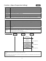
LMAP03U
Function – [Local Remote Controller Setting]
Function
[Time Stamp]
Description
Setting the time of the local remote controller.
Using NV
【nviRmTime】
Control unit
All local remote controllers
Outline of
operation
Set the local remote controller’s time.
Function
[Request Limit Temperature Setting Range] [Request Simplified Locking]
Description
Setting the limit on the temperature range that can be set with the local remote controller and the simplified
locking of operation.
Using NV
【nviRmLim】 【nviRmLck】
Control unit
All local remote controllers
Outline of
operation
"Set temperature range limit" Limits the temperature range that can be set with the local remote controller.
Limited temperature range: Cooling/drying lower limit temperature, heating upper limit temperature
"Simplified locking" Locks simply the operation of local remote controllers.
Operation items to set: All operation or the operation other than ON/OFF
At setting of the set temperature range and simplified locking, the display detail of the local remote controller can
also be set.
Display to be set: Display of actual operation mode under automatic operation and room temperature
Each set value is to be prepared by the configuration property.
Communication
BMS
RC (All)
LM-AP
[hhmmdd] setting
① Setting from BMS
[hhmmdd] setting
Renewal
Restrictions
- Types of local remote controllers
This function is only effective to use ME remote controller for the local remote controller.
By using ME remote controller, it is also effective to control OA processing unit among the ventilation units individually operated.
(The other models than LOSSNAY can not be controlled with ME remote controller when they are operating individually.)
- Mode selection when temperature set range is limited
When limiting the temperature set range, the automatic mode can not be selected. The operation mode changes to the fan operation
when the setting is changed.
Under the circumstance, please change the operation mode after setting the temperature set range.
43
LMAP03U
Function – [Space Temperature]
Function
[Space Temperature State]
Description
The room temperature designed to be measured by the indoor unit will be measured.
Using NV
【nvoSpaceTemp_n】
Control unit
Indoor unit
Outline of
operation
The room temperature (or inlet temperature) is measured.
Measuring temperature range: -10ºC ~ 50ºC, Temperature unit: 1.0ºC
For the measuring sensor, select the indoor unit inlet or remote controller sensor in the setting of indoor units.
The output for changes will be output at the change exceeding a certain change range.
Even in the case of no change, the current value will be output after a certain time is elapsed.
The value of the changing range is set by the configuration property.
Communication Image
BMS
IC
LM-AP
Space temp. demand
Renewal
The output for changes will be
output at the change exceeding a
certain change range.
state [xx℃]
state [xx℃]
Update interval(*1)
Space temp. demand
Renewal
The current value will be output
after a certain time is elapsed.
state [xx℃]
state [xx℃]
*1: Setting by Send Heartbeat_2【nciSndHrtBt_2】
Restrictions
- A difference of the display value of local remote control and BMS
With monitor timing, the display value of local remote control and BMS may change.
- Depending on the connecting number of indoor unit, the monitor interval that can be set is different.
To set a periodical monitor interval below 10 minutes, it is required to change SW1-3 on LM ADAPTER to ON. Please make the
connecting number 30 sets or less.
- The changing range: 0.5 ℃~2.0 ℃, Temperature unit: 0.5 ℃
Operated for 0.49℃ or less (except –0.01 ℃) --- Set to 0.5 ℃
Operated for –0.01℃ --- Set to 1.0 ℃
Operated for 2.01℃ or more --- Set to 2.0℃
44
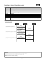
LMAP03U
Function – [Set Point]
Function
[Setpoint] [Setpoint State]
Description
Setting and monitoring the target temperature of indoor units.
Using NV
LMAP02-E: 【nviSetPoint_n】 【nvoSetPoint_n】
LMAP03U : 【nviSetP_n】 【nvoSetP_n】
Control unit
Indoor unit
Outline of
operation
The target room temperature for each indoor unit is set and monitored.
In accordance with the operation mode of indoor units, the temperature
range that can be set is different.
Set temperature unit: 1.0ºC
Mode
Setting Range
Auto
19 ~28 ℃
Cool
19 ~30 ℃
Heat
17 ~28 ℃
Dry
19 ~30 ℃
Fan
Not used
Communication Image
BMS
① Operation from BMS
IC
LM-AP
[xx℃] setting
[xx℃] setting
state [xx℃]
state [xx℃]
state [xx℃]
state [xx℃]
② Operation from local
remote controller
Restrictions
- To set temperature from the Building management system, set so that it stays within the set temperature range above.
- The action by the setting out of the set temperature range differs depending on the operation mode at that time.
<At cooling/drying mode> Operated for 19ºC or less, or 31ºC or more - - - Set to 19ºC, 30ºC respectively
<At heating mode> Operated for 17ºC or less, or 29ºC or more - - - Set to 17ºC, 28ºC respectively
<At automatic mode> Operated for 19ºC or less, or 29ºC or more - - - Set to 19ºC, 28ºC respectively
45
LMAP03U
Function – [Fan Speed]
Function
[Request FanSpeed] [FanSpeed State]
Description
Setting and monitoring the airflow rate of indoor units and individually operating ventilation units (not interlocked
with indoor units).
Using NV
【nviFanSpeed_n】 【nvoFanSpeed_n】
Control unit
Indoor unit
Outline of
operation
The airflow rate (High/Med.2/Med.1/Low) for each unit is set and monitored.
Communication Image
BMS
① Operation from BMS
IC
LM-AP
[High] operation
[High] operation
state [High]
state [High]
state [Low]
state [Low]
Restrictions
- Airflow setting value and setting operation by unit types
3-speed model: Setting to Med.2 operates in the Med.1 airflow.
2-speed model: Setting to Med 2 or Med 1 operates in the low airflow rate.
1-speed model: Setting to Med 2, Med 1 or Low operates in the high airflow rate.
46
② Operation from local
remote controller
LMAP03U
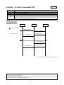
Function – [Forced Thermostat OFF]
Function
[Request Forced Thermostat OFF] [Forced Thermostat OFF State]
Description
Setting the Indoor unit forcibly to thermostat OFF.
Using NV
【nviThermoOff_n】 【nvoThermoOff_n】
Control unit
Indoor unit
Outline of
operation
Indoor unit is forcibly set to thermostat OFF.
The indoor unit being set to thermostat OFF will be in the thermostat OFF status regardless of operating
conditions (i.e. room temperature, set temperature, etc.).
Communication Image
BMS
IC
LM-AP
① Operation from BMS
[Enable] operation
[Enable] operation
Effective Time(*1)
state [Enable]
state [Enable]
[Disable] operation
state [Disable]
state [Disable]
*1: Setting by Receive Heartbeat_2【nciRcvHrtBt_2】
Restrictions
- Effective time of forced thermostat OFF
The thermostat OFF will automatically be cancelled if it is not renewed or poll/fetch demand is not presented during the effective
time being set by the “Receive Heartbeat 2【nciRcvHrtBt 2】”.
47
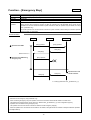
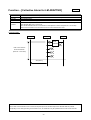
Function – [Emergency Stop]
LMAP03U
Function
[Request All Off] [Emergency State]
Description
Applying emergency stop collectively to all units controlled by LM ADAPTER.
Using NV
【nviAllOff】
Control unit
All of indoor units controlled by LM ADAPTER
Outline of
operation
The indoor units and ventilation units being controlled by LM ADAPTER are stopped collectively.
During the time when emergency stopping is valid, the operation from LM ADAPTER will be invalid. As the
operation from the local remote controller or system controller is valid, the operation may be started, but it stops
soon. (LMAP03U only)
To prohibit operation from the local remote controller or system controller, use the setting for collective operation
prohibit together in combination.
Communication
BMS
① Operation from BMS
IC (All)
LM-AP
[Stop] operation
[Stop] operation
state [Stop]
state [Stop]
Effective Time(*1)
② Operation from BMS during
emergency stop
[Run] operation
state [Run]
state [Run]
③ Operation from local
remote controller
*1: Setting by Effective Time_1【nciEffectTm_1】
Restrictions
- Effective time of emergency stop (LMAP03U only)
When conducting emergency stop, the operation control from LonWorks network will be invalid for a certain time.
The effective time mentioned here can be set by the “Effective time_1【nciEffectTm_1】” of the configuration property.
- Operation of air conditioner during emergency stop
The operation from the local remote controller is valid even under emergency stopping.
When the operation from the local remote controller is not desired, use together with the variable of “Request Collective Operation
prohibit【nviAllPro】”.
48
LMAP03U
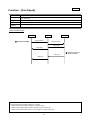
Function – [Model Code]
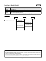
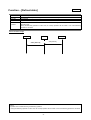
Function
[Mode Code]
Description
Outputting the capacity code of indoor unit and OA processing unit.
Using NV
【nvoIcMdlSize_n】
Control unit
Indoor unit
Outline of
operation
The capacity code indicating the capacity of indoor unit and OA processing unit is output.
This is used for the apportioning of charge, etc.
As this variable is not provided by the event output, acquire the data by Polling or Fetching.
Communication
BMS
① Polling or Fetching from BMS
IC
LM-AP
Poll demand
demand [Model Code]
output [Model Code]
output [Model Code]
Restrictions
- About the output at changing
This variable is of universal not applicable to the output at changing. Use the Poll or Fetch demand for acquisition as shown above.
- Models for which indoor capacity code can not be output
Since the general/industrial application packaged air conditioner units and ventilation units (excluding OA processing units) have no
information on the indoor unit capacity code, the code will not be output. (Default value)
49
LMAP03U
Function – [Collective Alarm for LM ADAPTER]
Function
[Collective Alarm for LM ADAPTER]
Description
Monitoring collectively the communication state of indoor units controlled by LM ADAPTER
Using NV
【nvoAllAlarmLMAP】
Control unit
All of indoor units controlled by LM ADAPTER
Outline of
operation
Alarm will be output if communication error occurs between the indoor unit and ventilation unit being controlled
with LM ADAPTER even on the one set.
Error will be detected when the communication is interrupted for a certain time (about 50 ~ 60 minutes).
When all communication errors are restored, the error will be restored as a result.
Communication
BMS
IC
LM-AP
Error
occurred
Under communication
abnormal detection
(about 50 – 60 minutes)
state [Alarm]
Cautions
- Even under a communication error occurred, the request input to and the state output from LM ADAPTER are possible.
- Depending on the cause generating communication error, air conditioners may be operated from the local remote controller.
50
LMAP03U
Function – [Defrost state]
Function
[Defrost State]
Description
Monitoring collectively the defrosting state of indoor units controlled by LM ADAPTER.
Using NV
【nvoDefrost】
Control unit
All of indoor units controlled by LM ADAPTER
Outline of
operation
Output will be commenced if even one of the indoor units being controlled by LM ADAPTER enters into
defrosting state.
During the defrosting operation of indoor unit, the run/stop operation will be invalid. It runs if the defrosting
operation is cancelled.
Communication Image
BMS
IC
LM-AP
state [Defrost]
state [Defrost]
Caution
- Operation of air conditioner during the defrosting operation
During the defrosting operation of indoor unit, the run/stop operation will be invalid. It runs if the defrosting operation is cancelled.
51
LMAP03U
Function – [Group Number]
Function
[Group Number]
Description
Outputting group information on the indoor unit or ventilation unit.
Using NV
【nvoGroup_n】
Control unit
Indoor unit
Outline of
operation
The group information (No.) of indoor unit or individually operating ventilation unit (not locked with indoor unit)
will be output. As this variable is not applied with the event output, acquire the data by Poll or Fetch demand.
The group information will only be set when grouping is performed with other system controller.
Communication
BMS
LM-AP
IC
① Polling or Fetching from BMS
Poll demand
output [Group Number]
Restrictions
- About output at changing
This variable is of universal and not applicable to the output at changing. Use the Poll or Fetch demand for acquisition as shown
above.
- Condition to output indoor unit group information
The group information will be output only when using other system controller like the centralized controller together in combination.
52
APPENDIX 2. Outline of Functions – Configuration Properties
-
Models
LMAP03U
-
Functions
「Minimum Send Time」
「Send Heartbeat Start Time」
「Send Start Time」
「Initial Output」
「Send Heartbeat_1」
「Send Heartbeat_2」
「Receive Heartbeat_1」
「Receive Heartbeat_2」
「Effective Time_1」
「Effective Time_2」
「Effective PollFetch」
「Effective Offline Mode」
「Space Temperature Setting」
「Limit Temperature Setting Range」
「Local Operation Lock」
「Local Display Setting」
「Communication Timing」
53
LMAP03U
Function – [ Minimum Send Time]
Function
[Minimum Send Time]
Description
Defines the minimum send time between the output network variables.
Using CP
【nciMinOutTm】
Control unit
LM ADAPTER
Relating CP
Nothing
Data holding
Memorizing set values in nonvolatile memory.
Reference NV
Variable output previously (in a unit of same indoor unit)
Purpose
When a state change occurs continually, the variable will be output with a certain interval not to output all state
changes.
Outline of
operation
When a state change occurs on the same unit that output previously, the output at changing will not be provided
within the set time. It will be supplied after elapsing the set time.
When the unit other than that output previously changes its state, it will be output even within the set time.
Communication Image
BMS
LM-AP
IC_01
IC_01[Run]
IC_01[Run]
【nciMinOutTm】
IC_01[Stop]
IC_01[Stop]
IC_01[Fan]
①Same indoor unit state changing
IC_01[Cool]
【nciMinOutTm】
IC_01[Cool]
IC_02[Run]
②Different indoor unit state changing
IC_02[Run]
【nciMinOutTm】
IC_01[Run]
IC_01[Run]
Cautions
- Effective for the output interval between the output variables on a same indoor unit.
- Unable to keep the output interval between different indoor units.
- Only the bound variables are output.
54
IC_02
LMAP03U
Function – [ Send Heartbeat Start Time]
Function
[Send Heartbeat Start Time]
Description
Defines the start time of automatic updating at the powering of the LM ADAPTER.
Using CP
【nciStartHrtBt】
Control unit
LM ADAPTER
Relating CP
【nciSndHrtBt_1】 【nciSndHrtBt_2】
Data holding
Memorizing set values in nonvolatile memory.
Reference NV
Nothing
Purpose
This sets the start time of automatic updating at applying power to LM ADAPTER. When plural LM ADAPTERS
are installed, the concentration of automatic updating can be prevented.
In the case using the initial output to match the image, this can further be applied to delay the automatic
updating to avoid excess output during the initial outputting.
Outline of
operation
At the passing of the set time after applying power, the timer of “Send Heartbeat_1【nciSndHrtBt_1】” and “Send
Heartbeat_2【nciSndHrtBt_2】 is started validating the automatic updating. The output by the automatic updating
is invalid within the set time.
Communication Image
BMS
LM-AP
Power Recovery
【nciStartHrtBt】
IC_01[Stop]
IC_01[Cool]
IC_01[25℃]
【nciSndHrtBt_1】
IC_01[LOSSNAY ventilation]
IC_01[High]
IC_01[Stop]
IC_01[Cool]
【nciSndHrtBt_1】
:
:
:
Cautions
- The bound variables will only be supplied.
- To use the initial output, set the start time for updating to initiate after the initial output.
55
IC_01
LMAP03U
Function – [Send Start Time]
Function
[Send Start Time]
Description
Defines the start time of the output network variable change at powering of LM ADAPTER.
Using CP
【nciStartOutTm】
Control unit
LM ADAPTER
Relating CP
Nothing
Data holding
Memorizing set values in nonvolatile memory.
Reference NV
Nothing
Purpose
This is to set the start time of output at changing when LM ADAPTER is powered. When the plural LM
ADAPTERS are installed, the concentration of the output at changing can be prevented.
In the case using the initial output to match the image, this can further be applied to delay the automatic
updating to avoid excess output during the initial outputting.
Outline of
operation
The output at changing will be effective when the set time is passed after powering. The status change within the
set time will be applied with the output at changing when passing the set time.
Communication Image
BMS
LM-AP
IC_01
Power Recovery
IC_01[Run]
①Status change within the set time
IC_01[Stop]
IC_01[Stop]
IC_01[Run]
IC_01[Run]
②Status change when passing the set time
Cautions
- After initializing LM ADAPTER, the request before the starting of the output at changing will be valid, but the state change will not be
provided.
- Only the bound variables are output.
56
LMAP03U
Function – [Initial Output]
Function
[Initialize Start Time] [Initialize Send Time_1] [Initialize Send Time_2]
Description
Defines the time to start the output when the output network variables change at LM ADAPTER power on, and
the minimum send time between the output network variables at initial output.
Using CP
【nciInitStartTm】 【nciInitOutTm_1】 【nciInitOutTm_2】
Control unit
LM ADAPTER
Relating CP
Nothing
Data holding
Memorizing set values in nonvolatile memory.
Reference NV
Nothing
Purpose
At the powering of LM ADAPTER, initial output will be provided to match the image of the indoor unit held by the
Building management system and that of the current state.
Outline of
operation
After passing the set time, the output variable will be supplied starting from No.1 unit in order.
The transmission interval between each unit【nciInitOutTm_2】 and that between the variables【nciInitOutTm_1】
are set by each configuration property respectively.
Communication Image
BMS
LM-AP
IC_01
Power Recovery
Monitoring[IC_01]
【nciInitStartTm】
Monitorign[IC_02]
①Initial output : [IC_01]
【nciInitOutTm_1】
【nciInitOutTm_1】
【nciInitOutTm_2】
【nciInitOutTm_1】
【nciInitOutTm_1】
②Initial output : [IC_02]
【nciInitOutTm_1】
【nciInitOutTm_2】
Caution
- Only the bound variables are output.
57
IC_02
LMAP03U
Function – [Send Heartbeat_1]
Function
[Send Heartbeat_1]
Description
Defines the time between the previous and next updating.
Using CP
【nciSndHrtBt_1】
Control unit
LM ADAPTER (in a unit of same indoor unit)
Relating CP
【nciStartHrtBt】
Data holding
Memorizing set values in nonvolatile memory.
Reference NV
Output of the previous nvoOnOff_n
Purpose
This is to use for preventing the non-agreement of the image when the output of LM ADAPTER is failed to
receive normally by the recipient.
Outline of
operation
When the set time is passed after the automatic updating or outputting at changing of the previous
【nvoOnOff_n】 (On/Off run state), the objective variable will be updated (output). In this case, the latest value
held by LM ADAPTER will be supplied even when the data has no change.
Communication Image
BMS
LM-AP
IC_01
IC_01[Run]
IC_01[Cool]
①In the case of no changing
IC_01[25℃]
:
After passing the set time
:
IC_01[Run]
IC_01[Cool]
②When except ON/OFF state changes
IC_01[25℃]
IC_01[Heat]
IC_01[Heat]
After passing the set time
IC_01[Run]
③When ON/OFF state changes
IC_01[Stop]
IC_01[Stop]
Outputs to the timing which changed.
IC_02[Run]
④Different indoor unit state changing
IC_02[Run]
IC_01[Stop]
IC_01[Heat]
After passing the set time
IC_01[25℃]
Cautions
- The transmission timing between indoor units may be duplicated occasionally.
- Make sure to set the start time of automatic updating.
- Only the bound variables will be output.
58
IC_02
LMAP03U
Function – [Send Heartbeat_2]
Function
[Send Heartbeat_2]
Description
Defines the time between the previous and next updating.
Using CP
【nciSndHrtBt_2】
Control unit
LM ADAPTER (in a unit of same indoor unit)
Relating CP
【nciInitStartTm】 【nciAnlgMonTm】 【nciAnalogWidth】
Data holding
Memorizing set values in nonvolatile memory.
Reference NV
Output of the previous nvoSpaceTemp
Purpose
This is to use for preventing the non-agreement of the image when the output of LM ADAPTER is failed in
normal receiving by the recipient.
Outline of
operation
When the set time is passed after the automatic updating or outputting at changing of the previous
nvoSpaceTemp_n (room temperature state output), the objective variable will be updated (output). In this case,
the latest value held by LM ADAPTER will be supplied even when the data has no change.
Communication Image (In the case of spacetemp width )
BMS
LM-AP
IC_01
IC_02
IC_01[25.5℃] ※
IC_01[25.5℃]
IC_01[25.6℃]
width = 0.1℃
IC_01[25.8℃]
width = 0.3℃
IC_01[26.0℃]
width = 0.5℃
IC_01[26.6℃] ※
width = 1.1℃
IC_01[26.1℃]
width = 0.5℃
IC_01[25.9℃]
width = 0.7℃
IC_01[25.8℃]
width = 0.8℃
【nciSndHrtBt_2】
①In the case of no changing
IC_01[25.8℃]
After passing the set time
②In the case of changing
IC_01[26.6℃]
Outputs to the timing which changed.
【nciSndHrtBt_2】
After passing the set time
IC_01[25.9℃]
【nciSndHrtBt_2】
③Different indoor unit changing
IC_02[25.0℃]
IC_02[25.0℃]
IC_01[25.7℃]
After passing the set time
width = 0.9℃
IC_01[25.7℃]
※ Reference value
Cautions
- The transmission timing between indoor units may be duplicated occasionally.
- Make sure to set the start time of automatic updating.
- Only the bound variables will be output.
59
LMAP03U
Function – [Recerive Heartbeat]
Function
[Receive Heartbeat_1] [Receive Heartbeat_2]
Description
Defines the maximum elapse time from the last update of the network variables.
Using CP
【nciRcvHrtBt_1】 【nciRcbHrtBt_2】
Control unit
LM ADAPTER
Relating CP
Nothing
Data holding
Memorizing set values in nonvolatile memory.
Reference NV
Objective variable lastly updated
Purpose
This is to be used to determine the operation when the periodical updating to LM ADAPTER is eliminated such
as in the case when the master system is downed or communication error
is occurred.
Outline of
operation
When the set time is passed after updating the network variable lastly (by renewing the set value for the input
network variable, and the poll/fetch demanding for the output network variable), the setting will automatically be
cancelled.
To continue the set state, update one of the variables of the objective unit (address) periodically.
Communication Image (In the case of local prohibit)
BMS
LM-AP
IC_01[Prohibit ON/OFF]
IC_01
IC_01[Prohibit ON/OFF]
①Update within the set time
IC_01[Prohibit ON/OFF]
IC_01[Prohibit ON/OFF]
②Monitor within the set
IC_01 Poll demand
IC_01[Prohibit ON/OFF]
③No update and monitor
within the set time
IC_01[Permit ON/OFF]
IC_01[Permit ON/OFF]
IC_01[Permit ON/OFF]
60
Function – [Effective Time_1]
LMAP03U
Function
[Effective Time_1]
Description
Defines the valid time of nviAllOff (Request All Off)
Using CP
【nciEffectTm_1】
Control unit
LM ADAPTER
Relating CP
Nothing
Data holding
Memorizing set values in nonvolatile memory.
Reference NV
nviAllOff
Purpose
The continuing time of emergency stopping is set.
During the emergency stopping, individual operation will be invalid.
Outline of
operation
"Emergency stop"
If emergency stop is requested by 【nviAllOff】(Request All Off), all units controlled by LM ADAPTER will be
stopped. The emergency stop effective status is valid during the set time. During this time, the ON/OFF
operation by 【nviOnOFF_n】(Request ON/OFF) is invalid. As the set time is passed, the emergency stopping
status will be cancelled making the ON/OFF operation by 【nviOnOff_n】valid.
Communication Image
BMS
LM-AP
IC (All)
[Emergency Stop]
[Stop] operation
state [Emergency Stop]
①Update within the set time
[Emergency Stop]
[Stop] operation
state [Emergency Stop]
IC_01[Run]
②Operation within the set
state [normal]
③No update within the set
Restrictions
- During a period when the emergency stopping is valid, individual ON/OFF operation will be invalid.
Cautions
-The operation with local remote controllers or system controllers is possible.
- When emergency stop is effectuated by using the set input of the system controller or the like, LM ADAPTER will not be under
emergency stopping.
61
LMAP03U
Function – [Effective Time_2]
Function
[Effective Time_2]
Description
Defines the valid time of nviAllPro (Request Collective Operation Prohibit)
Using CP
【nciEffectTm_2】
Control unit
LM ADAPTER
Relating CP
Nothing
Data holding
Memorizing set values in nonvolatile memory.
Reference NV
nviAllPro
Purpose
This is to set the time to continue collective operation prohibit.
During the time when the operation prohibit is valid, the individual operation prohibit setting will not be reflected.
Outline of
operation
"Collective Local Prohibit "
Upon receipt of collective operation prohibiting request by 【nviAllPro】(Request Collective Operation Prohibit),
the operation (ON-OFF mode/Temperature setting) of the local remote controller connected to all units
controlled with LM ADAPTER will be prohibited.
The operation prohibit is valid within the set time, and during this time, the setting by the operation prohibit of
the individual local remote controller (【nviProOnOff_n】【nviProMode_n】【nviProSetP_n】) will be reserved.
As the set time is passed, the collective operation prohibiting state is cancelled, and the operation prohibiting
request such as 【nviProOnOff】, etc. received during the effective time will be reflected.
Communication Image
BMS
LM-AP
IC (All)
[Enable] operation
[Prohibit (Batch)] operation
state [Enable]
①Update within the set time
[Enable] operation
[Prohibit (Batch)] operation
state [Enable]
IC_01[Prohibit ON/OFF]
②Operation within the set
[Permit (Batch)]
state [disable]
③No update within the set
IC_01[Prohibit ON/OFF]
Restrictions
- Operation prohibit state can not be cancelled by nviAllPro.
The time minimization of this configuration property should be applied.
Cautions
- The operation by the system controller is possible.
- The command from the LonWorks network under operation prohibit is valid.
62
Function – [Effective PollFetch]
LMAP03U
Function
[Effective PollFetch]
Description
Defines the presence of response to the output network variables Poll (Fetch) request.
Using CP
【nciPollFetch】
Control unit
LM ADAPTER
Relating CP
Nothing
Data holding
Memorizing set values in nonvolatile memory.
Reference NV
Nothing
Purpose
This is to use when not desiring to get a response under unstable state.
Outline of
operation
Under the conditions below, the response to Poll (Fetch) demand against the output variable will not be returned.
- Unit not being connected
- Unit with outdoor unit being not powered
- Communication with LM ADAPTER interrupted for a certain time
- Registration of LM ADAPTER to Master controller is not completed yet
Communication Image
BMS
LM-AP
IC_01
IC_02
IC_03
connected
connected
not connected
[no response] setting
Poll demand[IC_01]
①When [no response] setting
IC_01[Run]
Poll demand[IC_03]
[response] setting
Poll demand[ IC_03]
②When [response] setting
IC_03[Stop (initial value)]
Caution
- When the Ack service is employed, Ack will be responded.
63
Function – [Effective Offline Mode]
LMAP03U
Function
[Effective Offline Mode]
Description
Defines the offline mode setting when the LM ADAPTER power is turned ON.
Using CP
【nciOffline】
Control unit
LM ADAPTER
Relating CP
Nothing
Data holding
Memorizing set values in nonvolatile memory.
Reference NV
Nothing
Purpose
The mode will be fixed to judge whether the initialization is commenced at the powering of LM ADAPTER.
Outline of
operation
In the case when the OFF line mode is set in valid, the OFF line mode will forcibly be commenced for about 20
minutes after powering LM ADAPTER. If Poll (Fetch) demand is presented to the input variable and outdoor
variable during this time, the null will be responded.
After 20 minutes elapsed, ON line mode will be set.
Communication Image
BMS
LM-AP
IC_01
Power Recovery
NC no response
Initialization setting of LM ADAPTER
20 minutes after powering
[Query Status]
state [offline]
Poll demand[IC_01]
state [null]
[Query Status]
state [online]
Poll demand[IC_01]
state [Run]
Cautions
- To conduct binding, be sure to make the OFF line mode invalid.
- The mode change under OFF line mode will be invalid.
- This function is only effective during the initialization (20 minutes after powering) of LM ADAPTER.
64
Function – [Space Temperature Setting]
LMAP03U
Function
[Monitoring Time]
Description
Defines the indoor temperature monitor interval from the LM ADAPTER to the indoor unit.
Using CP
【nciAnlgMonTm】
Control unit
LM ADAPTER
Relating CP
【nciSndHrtBt_2】
Data holding
Memorizing set values in nonvolatile memory.
Reference NV
Nothing
Purpose
To be used to modify the monitoring interval of room temperature
Outline of
operation
With the set interval, room temperature is monitored for indoor units from LM ADAPTER.
Depending on the connecting number of indoor units, the monitor interval that can be set is different.
Function
[Spacetemp Width]
Description
Defines the minimum variation width of the output when 【nvoSpaceTemp_n】(Space Temperature) changes.
Using CP
【nciAnalogWidth】
Control unit
LM ADAPTER
Relating CP
【nciSndHrtBt_2】
Data holding
Memorizing set values in nonvolatile memory.
Reference NV
Nothing
Purpose
To be used for suppressing frequent outputs at the changes of room temperature
Outline of
operation
The output at changes will be provided if the status change of room temperature becomes more than the set
temperature range. The output at changes will not be provided if the status change of room temperature
becomes less than the set temperature range.
Changing range: 0.5 ℃~2.0 ℃, Temperature unit: 0.5 ℃
Communication Image
BMS
LM-AP
IC_01
Monitoring
[Room Temperature]
Response
Monitoring
[Room Temperature]
Response
【nciAnlgMonTm】
【nciAnlgMonTm】
Monitoring
[Room Temperature]
Response
【nciAnlgMonTm】
Restriction
- The set range differs depending on the connecting number of indoor units.
Caution
- To set a periodical monitor interval below 10 minutes, it is required to change SW1-3 on LM ADAPTER to ON. Please make the
connecting numbers 30 sets or less.
65
Function – [Limit Temperature Setting]
LMAP03U
Function
[Lower Setpoint Cooling] [Upper Setpoint Heating]
Description
Defines the limit temperature setting value for local remote controller.
Using CP
【nciCoolLrSetP】 【nciHearUpSetP】
Control unit
LM ADAPTER
Relating CP
【nciRmDsp_1】 【nciRmDsp_2】
Using NV
【nviRmLim】
Data holding
Memorizing set values in nonvolatile memory.
Reference NV
Nothing
Purpose
To be used for energy saving purpose by preventing cooling, drying and heating operation at excessive
temperature
Outline of
operation
With this configuration property, the lowest set temperature in cooling and drying and the highest set
temperature in heating are set to the local remote controller. The set detail will be reflected on the local remote
controller when "Valid" is requested by 【nviRmLim】.
Communication Image
BMS
①Setting change at [Lower temperature in cooling]
[Lower temperature in cooling] =20℃
LM-AP
nciCoolLrSetP
nviRmLim
[Upper temperature in heating] =28℃(initial value)
②Setting change at [Upper temperature in heating]
[Lower temperature in cooling] =20℃(no change)
RC
Lower cooling[20℃]
Upper Heating[28℃]
nciHeatUpSetP
nviRmLim
[Upper temperature in heating] =26℃
Lower Cooling[20℃]
Upper Heating[26℃]
③Setting initialize
[Lower temperature in cooling] = 19℃
nviRmLim
[Upper temperature in heating] = 28℃
Lower Cooling[19℃]
Upper Heating[28℃]
Restriction
- This is effective only for the standard local remote controllers with function to limit the set temperature range.
Cautions
- As the setting is applied to the local remote controller collectively, the setting can not be changed for the remote controller
individually.
- Changing the setting moves to the fan mode.
66
LMAP03U
Function – [Local Operation Lock]
Function
[Local Operation Lock]
Description
Defines the local remote controller simple lock setting value.
Using CP
【nciRmOpLck】
Control unit
LM ADAPTER
Relating CP
【nciRmDsp_1】 【nciRmDsp_2】
Using NV
【nviRmLck】
Data holding
Memorizing set values in nonvolatile memory.
Reference NV
Nothing
Purpose
To be used for limiting the switch operation of local remote controller collectively
Outline of
operation
With this configuration property, the limiting range of simplified locking function is set for the local remote
controller. The set detail will be reflected on the local remote controller when "Valid" is requested by
【nviRmLim】.
Communication Image
BMS
①Simplified locking [All buttons]
LM-AP
Setting
[nciRmOpLck: All buttons]
Setting
[nviRmLck: enable]
②Simplified locking [Except ON/OFF]
RC
Broadcast
Setting
[nciRmOpLck:
except ON/Off button ]
Setting
[nviRmLck: enable]
Broadcast
③Simplified locking [Cancelled: disable]
Setting
[nviRmLck: disable]
Broadcast
Restrictions
- Effective only for the local remote controller with function to limit switch operation
- Effective only for the local remote controller set to the standard model.
Caution
- Setting to local remote controllers collectively
67
Function – [Local Display Setting]
LMAP03U
Function
[Local Display_1] [Local Display_2]
Description
Defines the presence of the automatic actual operation mode display on the local remote controller.
Using CP
【nciRmDsp_1】 【nciRmDsp_2】
Control unit
LM ADAPTER
Relating CP
Nothing
Using NV
【nviRmLck】 【nviRmLim】
Data holding
Memorizing set values in nonvolatile memory.
Reference NV
Nothing
Purpose
Used for switching over the display of operation mode and room temperature alternately on the local remote
controller
Outline of
operation
"Automatic actual operation mode"
Selecting the presence of display for the operation mode (automatic cooling, automatic heating) actually
working on the models operable automatically.
"Room temperature display"
Selecting the presence of display for room temperature.
With this configuration property, the presence of display for the actual operation mode of local remote
controller is set. The set detail is reflected on the local remote controller at the renewal of 【nviRmLim】
and 【nviRmLck】.
Communication Image
BMS
① “Automatic actual operation mode “ changing
“Automatic actual operation mode[enable]
“Room temperature display “ [enable]
① “Room temperature display “ changing
“Automatic actual operation mode” [enable]
“Room temperature display “ [disable]
LM-AP
RC_101
Setting
[nciRmDsp_1]
Setting
[nviRmLck / nviRmLim]
“Automatic actual operation mode[enable]
“Room temperature display “ [enable]
Setting
[nciRmDsp_2]
Setting
[nviRmLck / nviRmLim]
“Automatic actual operation mode[enable]
“Room temperature display “ [disable]
Restrictions
- Effective only for the local remote controller with function to change over the presence of display
- Effective only for the local remote controller set to the standard model.
Caution
- Setting to local remote controllers collectively
68
Function – [Communication Timing]
LMAP03U
Function
[Communication Timing]
Description
Defines the network communication start timing at the powering of the LM ADAPTER.
Using CP
【nciSet_1】
Control unit
LM ADAPTER
Relating CP
【nciStartHrtBt】 【nciStartOutTm】 【nciInitStartTm】
Data holding
Memorizing set values in nonvolatile memory.
Reference NV
Nothing
Purpose
To be used for setting of the timing to start the operation of Neuron Chip after completing the initialization. While
the Neuron Chip is stopped during the initialization setting of LM ADAPTER with air conditioners.
Outline of
operation
At the set time after powering, the operation of Neuron Chip will start enabling the LonWorks communication of
LM ADAPTER.
Communication Image
BMS
① [initialize]
LM-AP
IC_01
Power Recovery
Poll demand
Initialization setting of LM ADAPTER
NC will not reply
Poll demand
response
BMS
②[setting time]
LM-AP
IC_01
Power Recovery
Poll demand
Initialization setting of LM ADAPTER
NC will not reply
Poll demand
Related configuration property
- Send Start Time 【nciStartOutTm】
- Send Heartbeat Start Time 【nciStartHrtBt】
- Initialize Start Time【nciInitStartTm】
Poll demand
response
Caution
- This does not represent the start timing of the output at changing (event output). Setting is required by the configuration property
(Send Start Time 【nciStartOutTm】) additionally.
69
3400 Lawrenceville Suwanee Road ● Suwanee, Georgia 30024
Toll Free: 800-433-4822 ● Toll Free Fax: 800-889-9904
Specifications are subject to change without notice.