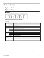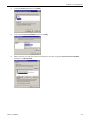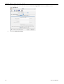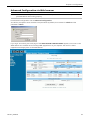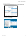
1
SIEMENS ADSL E-110/E-110-I
ETH & USB ComboRouter
User Manual
Rev:01_040220
2004-02-20
No part of this publication may be reproduced in any form by any means without the prior written
permission from Siemens Switzerland Ltd
SIEMENS ADSL E-110_E-110-I user manual
Safety Notes
For Installation
•
Use only the type of power source indicated on the marking labels.
•
Use only the power adapter supplied with the product.
•
Do not overload wall outlet or extension cables as this may increase the risk of electric shock or fire. If
the power cable is frayed, replace it with a new one.
•
Proper ventilation is necessary to prevent the product overheating. Do not block or cover the slots
and openings on the device, which are intended for ventilation and proper operation. It is
recommended to mount the product with a stack.
•
Do not place the product near any source of heat or expose it to direct sunshine.
•
Do not expose the product to moisture. Never spill any liquid on the product.
•
Do not attempt to connect with any computer accessory or electronic product without instructions
from qualified service personnel. This may result in risk of electronic shock or fire.
•
Do not place this product on an unstable stand or table.
For Using
•
Power off and unplug this product from the wall outlet when it is not in use or before cleaning. Pay
attention to the temperature of the power adapter. The temperature might be high.
•
After powering off the product, power on the product at least 15 seconds later.
•
Do not block the ventilating openings of this product.
•
When the product is expected to be not in use for a period of time, unplug the power cable of the
product to prevent it from the damage of storm or sudden increases in rating.
For Service
Do not attempt to disassemble or open covers of this unit by yourself. Nor should you attempt to service
the product yourself, which may void the user’s authority to operate it. Contact qualified service personnel
under the following conditions:
•
If the power cable or plug is damaged or frayed.
•
If liquid has been spilled into the product.
•
If the product has been exposed to rain or water.
•
If the product does not operate normally when the operating instructions are followed.
•
If the product has been dropped or the cabinet has been damaged.
•
If the product exhibits a distinct change in performance.
Warning
•
This equipment must be installed and operated in accordance with provided instructions.
•
This device complies with Part 15 of the FCC Rules. Operation is subject to the following two
conditions: (1) this device may not cause harmful interference, and (2) this device must accept any
interference received, including interference that may cause undesired operation.
Caution
•
ii
Any changes or modifications not expressly approved by the party responsible for compliance could
void the authority to operate equipment.
Rev:01_040220
Contents
Content
Safety Notes................................................................................................................................. i
Safety Notes................................................................................................................................ ii
For Installation.................................................................................................................... ii
For Using ............................................................................................................................ ii
For Service .......................................................................................................................... ii
Warning.............................................................................................................................. ii
Caution............................................................................................................................... ii
Content ............................................................................................................................................. iii
Before You Use................................................................................................................................... 1
Features ...................................................................................................................................... 1
System Requirements................................................................................................................. 2
Unpacking ................................................................................................................................... 2
Chapter 1: Overview .......................................................................................................................... 3
Physical Outlook ......................................................................................................................... 3
Physical Outlook ......................................................................................................................... 3
Front Panel ......................................................................................................................... 3
Rear PanelRear Panel .......................................................................................................... 4
Chapter 2: Installation ....................................................................................................................... 5
Choosing a place for the ADSL Router ....................................................................................... 5
Connecting the ADSL Router ...................................................................................................... 5
Analog (PSTN) installation................................................................................................... 5
ISDN installation ................................................................................................................. 6
USB driver installation ................................................................................................................ 7
Install the USB driver ........................................................................................................... 7
Uninstall the USB driver....................................................................................................... 8
Chapter 3: Configuration ................................................................................................................... 9
Step 1: Configure TCP/IP on Client PC......................................................................................... 9
For Windows 95 .................................................................................................................. 9
For Windows 98 and Windows 98 SE ................................................................................. 13
For Windows ME ............................................................................................................... 17
For Windows NT................................................................................................................ 18
For Windows 2000 ............................................................................................................ 22
For Windows XP ................................................................................................................ 25
For Macintosh OS 8.6 and 9.x............................................................................................ 26
For Macintosh OS 10.x ...................................................................................................... 27
Renew IP Address on Client PC................................................................................................. 29
For Windows 98 and Windows 98 SE ................................................................................. 29
For Windows ME ............................................................................................................... 30
For Windows NT................................................................................................................ 30
For Windows 2000 ............................................................................................................ 31
For Windows XP ................................................................................................................ 31
Step 2: Quick Configuration via Web browser ......................................................................... 32
Internet Access.................................................................................................................. 32
Rev:01_040220
iii
SIEMENS ADSL E-110_E-110-I user manual
Advanced Configuration via Web browser .............................................................................. 33
Main Menu ....................................................................................................................... 34
Commonly Used Buttons and Icons.................................................................................... 34
Viewing Basic System Information..................................................................................... 35
Quick Configuration .......................................................................................................... 36
Committing Changes to Permanent Storage ...................................................................... 37
Rebooting the device using Configuration Manager........................................................... 37
Sub-Menus........................................................................................................................ 38
Chapter 4: Advanced Configuration................................................................................................ 40
Configuring IP Routes............................................................................................................... 40
DHCP Configuration.................................................................................................................. 41
Configuring DHCP Server ................................................................................................... 41
Configuring DHCP Relay .................................................................................................... 44
NAT Configuration .................................................................................................................... 45
Viewing Your NAT Configuration ....................................................................................... 45
Viewing NAT Rules and Rule Statistics................................................................................ 48
Viewing Current NAT Translations ..................................................................................... 48
Adding NAT Rules.............................................................................................................. 49
RIP Configuration...................................................................................................................... 54
Configuring the RIP ........................................................................................................... 54
Viewing RIP Statistics......................................................................................................... 55
Firewall, IP Filters and Blocked Protocols................................................................................. 56
Firewall Configuration ...................................................................................................... 56
IP Filter Configuration ....................................................................................................... 58
To Block Specific Protocols................................................................................................. 64
Administration Tasks ................................................................................................................ 65
Changing the System Date and Time ................................................................................. 65
User Configuration ............................................................................................................ 65
Image Upgrade ................................................................................................................. 66
View System Alarms.......................................................................................................... 67
Diagnostics ....................................................................................................................... 67
Port Settings ..................................................................................................................... 68
View DSL Parameters................................................................................................................ 69
Chapter 5: Connection Modes ......................................................................................................... 71
Bridge Mode ............................................................................................................................. 71
Part 1: Configuring the ADSL Router .................................................................................. 71
Part 2: Check your connection status. ................................................................................ 74
Part 3: Configuring the PC. ................................................................................................ 74
PPP Connection Mode............................................................................................................... 74
Part 1: Configuring the ADSL Router .................................................................................. 74
Part 2: Check your connection status. ................................................................................ 76
Part 3: Configuring the PC. ................................................................................................ 76
Router Connection Mode ......................................................................................................... 77
Part 1: Configuring the ADSL Router .................................................................................. 77
Part 2: Check your connection status. ................................................................................ 78
Part 3: Configuring the PC. ................................................................................................ 78
Chapter 6: Troubleshooting............................................................................................................. 79
Chapter 7: Glossary.......................................................................................................................... 81
iv
Rev:01_040220
Contents
Appendix: Specification................................................................................................................... 83
Software ................................................................................................................................... 83
Hardware .................................................................................................................................. 84
Rev:01_040220
v
Before You Use
Before You Use
The SIEMENS ADSL E-110/E-110-I is an Asymmetric Digital Subscriber Line (ADSL) Router. With the
asymmetric technology, this device runs over standard copper phone lines. In addition, ADSL allows you to
have both voice and data services in use simultaneously all over one phone line.
The SIEMENS ADSL E-110/E-110-I is designed to offer cost-effective high-speed services for home or office
users. It provides a downstream rate of up to 8 Mbps and upstream rate of up to 1 Mbps for ADSL
connection, even offers auto-negotiation capability for different flavors (ANSI T1.413 Issue 2, G.lite, G.dmt
for Annex A, G.dmt for Annex B or G.hs) according to central office DSLAM’s settings (Digital Subscriber
Line Access Multiplexer). Also the feature-rich routing functions are seamlessly integrated to ADSL service
for existing corporate or home users. Now users can enjoy various bandwidth-consuming applications via
the SANTIS ADSL Router.
Features
ADSL Compliance
•
ANSI T1.413 Issue 2
•
ITU G.992.2 Annex A (G.lite)
•
ITU G.992.1 Annex A (G.dmt)
•
ITU G.992.1 Annex B (G.dmt)
•
ITU G.994.1 (G.hs)
ATM Features
•
Compliant to ATM Forum UNI 3.1 / 4.0 Permanent Virtual Circuits (PVCs)
•
Support up to 8 AAL5 Virtual Circuit Channels (VCCs) for UBR, CBR and GFR service classes
•
Provides ATM layer functionality
•
Provides adaptation layer (AAL5) functionality
•
Performs the traffic shaping and scheduling per ATM port
•
Supports PPP encapsulation over ATM (PPPoA) and PPP over Ethernet (PPPoE)
•
ADSL-aware CAC
•
Support for F5 AIS, RDI and loopback cells
Bridging Features
•
Up to 1000 hosts
•
Supports transparent bridging as specified in IEEE 802.1D Transparent Bridging
•
Supports bridged PDU encapsulation (RFC 2684)
•
MAC-level filter to accept/deny packets based on rules applicable at the MAC level
Routing Features
•
Network Address Translation (NAT)
•
IP filtering and raw filtering
•
Dynamic IP address allocation is supported through DHSP and IPCP
•
Point-to-point Protocol (PPP): PPPoA, PPPoE, PAP or CHAP for user authentication, Routing information
Protocol (RIP) v1 and v2
Security Features
•
PAP (RFC1334), CHAP (RFC1994) for PPP session
•
Firewall support IP packets filtering based on IP address/Port number/Protocol type and TCP code field
flags
•
Intrusion Detection provides protection from a number of attacks (such as SYN/FIN/RST Flood, Smurf,
WinNuke, Echo Scan, Xmas Tree Scan, etc)
Rev:01_040220
1
SIEMENS ADSL E-110_E-110-I user manual
Configuration and Management
•
DSL Forum TR37-compliant auto configuration
•
SNMPv1 over DSL or Ethernet for access to the MIB-II (router only)
•
CLI (Command Line Interface) via serial interface or Telnet over Ethernet or DSL
•
Web-based Graphical User Interface (GUI) enabling end-user device configuration via Web browser
•
Update of boot image configuration data over TFTP/FTP
System Requirements
For using this, you have to make sure you have the following that installed on the clients:
•
Operating System must be Windows 95/98/98 SE/ME/NT/2000/XP or Macintosh 8.6/9.x/10.x
•
10/100 Base-T NIC
•
10/100 Base-T (UTP) network cable
Unpacking
Check the contents of the package against the pack contents checklist below. If any of the items is missing,
then contact the dealer from whom the equipment was purchased.
2
•
ADSL Router
•
Power Adapter
•
RJ-11 ADSL Line Cable
•
RJ-45 Ethernet Cable
•
CDROM with Quick Start Guide / User Manual
Rev:01_040220
Chapter 1: Overview
Chapter 1: Overview
Physical Outlook
Physical Outlook
Front Panel
The following illustration shows the front panel of the ADSL Router:
LED Indicators (Front Panel System Messages)
The ADSL Router is equipped with orange LEDs on the front panel as described in the table below (from
left to right):
LED
Status
Description
Power
On
Unit is powered on.
Off
Unit is powered off.
Status
Blinking
Flashes to indicate that the device software is operational.
ADSL
Link/Act
Short
Blinking
The Router Modem is in ‘training’
OFF
ADSL link is established
Irregular
Blinking
Indicates ADSL traffic
On
Ethernet link is established
Off
No Ethernet link
Irregular
Blinking
Indicates Ethernet traffic
On
USB link is established
Off
No USB link
Irregular
Blinking
Indicates USB traffic
Ethernet
Link/Act
USB
Link/Act
Rev:01_040220
3
SIEMENS ADSL E-110_E-110-I user manual
Rear PanelRear Panel
The following figure illustrates the rear panel of your ADSL Router.
4
ADSL
Connects the device to an ADSL telephone jack using the supplied cable.
USB
Connects the device to the USB port on your PC.
Ethernet
Connects the device to your PC's Ethernet port, or to the uplink port on your LAN's hub,
using the cable provided.
Reset Button
Reset to factory defaults.
To reset the device to factory defaults, you don’t need to power off the device. Just
push a paper clip into the hole. Press down the button for 3 times and then release.
Then wait for the device to finish boot-up.
9V
Connects to the supplied power converter cable.
1A
Rev:01_040220
Chapter 2: Installation
Chapter 2: Installation
Choosing a place for the ADSL Router
1.
Place the ADSL Router close to ADSL wall outlet and power outlet for the cable to reach it easily.
2.
Avoid placing the device in places where people may walk on the cables. Also keep it away from
direct sunshine or heat sources.
3.
Place the device on a flat and stable stand.
Connecting the ADSL Router
Follow the steps below to connect the related devices.
Note: For ADSL standard, a PSTN Microfilter or an ISDN Splitter is necessary on subscriber’s premise to
keep the telephone and ADSL signals separated, giving them the capability to provide
simultaneous Internet access and telephone service on the same line.
Analog (PSTN) installation
If your telephone service is analog (SIEMENS ADSL E-110), proceed as follows to install your Hardware:
Remove the end of the phone line from your phone connector and plug it into the “LINE” plug of the PSTN
Microfilter. Use another phone line to connect your phone and Microfilter. Plug this phone line into the
“PHONE” plug of the ADSL Microfilter, and plug the other end of the line onto your phone.
Y-Line Filters
1.
Unplug the device’s cable from the phone jack.
2.
Plug the Y-Line Filter into the phone jack.
3.
Plug the phone cable (or other device cable) into the “PHONE” jack of your Y-Line Filter.
4.
Plug the ADSL cable into the “ADSL” jack of your Y-Line Filter.
2.
3.
4.
Rev:01_040220
5
SIEMENS ADSL E-110_E-110-I user manual
ISDN installation
If your telephone service is ISDN (SIEMENS ADSL E-110-I), proceed as follows to install your Hardware:
1.
Remove the U-Line (incoming line) form your ISDN NT and plug it into the “LINE” plug of the ISDN
Splitter. Use another phone line to connect your ISDN NT with your ISDN Splitter. Plug this phone line
onto the “PHONE” plug of the ADSL splitter, and plug the other end of the line into the U-Line plug of
your ISDN NT.
PHONE port
ISDN
U-Line
LINE port
ISDN NT
MODEM port
6
2.
Use the line to connect the ADSL Microfilter or Splitter and your ADSL LAN port.
3.
Please attach one end of the Ethernet cable with RJ-45 connector to the “LAN” port of your ADSL
Router.
4.
Connect the other end of the cable to the Ethernet port of the client PC.
5.
Connect the supplied power adapter to the PWR port of your ADSL Router, and plug the other end to
a power outlet.
6.
Turn on the power switch.
Rev:01_040220
Chapter 2: Installation
USB driver installation
Install the USB driver
Note: The USB driver is only working on the following operating systems (OS):
Windows 98, Windows 98SE, Windows ME, Windows 2000 and Windows XP
If your Router is NOT equipped with an Ethernet interface you have to install first the USB driver in order to
be able to configure your ADSL Router. For the driver installation proceed as follows:
Note: Windows 98 users need the Windows 98 CD-ROM to complete the installation.
1a.
With your computer off, connect the USB cable to the USB port on your computer (plug it in a
separate USB port on the PC – preferably without using a hub).
1b. Do NOT connect your ADSL router to your computer now.
2.
Turn on your computer.
3.
Insert the Siemens installation CD-ROM in your CD-ROM drive.
4.
The installation procedure will start automatically and the following window appears:
Note: In case the setup wizard does not start automatically, open a “Run” window via “Start” “Run” and
enter the path D:\setup.exe, where “D” represents the drive letter of the CD-ROM drive.
5.
Click on Next. The software will be installed after which the following window appears:
6.
Connect the USB cable to your ADSL router. The driver will be installed automatically.
Note for Windows 98 users:
Rev:01_040220
If prompted, you need to insert the Windows 98 CD-ROM in your CD-ROM
drive to complete the installation.
7
SIEMENS ADSL E-110_E-110-I user manual
7.
You will be asked whether the PC should be restarted. Click on Close.
The PC will be restarted and the following window appears:
8.
Click on Finish.
Uninstall the USB driver
Note:
Do not unplug the ADSL router from the PC until the uninstaller asks!From your PC desktop
click Start Programs Siemens DSL Modem Uninstall.
1.
A message will be displayed asking you to confirm the removal of the SANTIS ADSL router software,
click on Yes.
2.
The “Information” window will be displayed reminding you NOT to unplug the USB cable until the
uninstall process has been completed. Click OK.
3.
A message will be displayed, that you now can unplug your ADSL router from the computer. Unplug
your ADSL router from your computer. Click OK.
4.
The Reboot window indicates successful completion of the uninstall process.
Remove any disks from the drives. Select the Yes, reboot the computer now option by clicking in the
radio button to its left, and click Close.
8
Rev:01_040220
Chapter 3: Configuration
Chapter 3: Configuration
In order to access the Internet through the router, you must check the TCP/IP settings before configuring
the router.
Step 1: Configure TCP/IP on Client PC
To access the ADSL Router via Ethernet, the host computer must meet the following requirements:
•
With Ethernet network interface.
•
Must have TCP/IP protocol installed.
•
Set client PC with obtain an IP address automatically.
•
With a Web browser installed: Internet Explorer 5.x or later.
The ADSL Router is configured with the default IP address of 192.168.1.1 and subnet mask of
255.255.255.0. As the DHCP server is Enabled by default, the DHCP clients should be able to access the
ADSL Router. Or you could assign an IP address to the host PC first for initial configuration.
You also can manage the ADSL Router through a Web browser-based manager: ADSL ROUTER CONTROL
PANEL. The ADSL Router manager uses the HTTP protocol via a Web browser to allow you to set up and
manage the device.
To configure the device via Web browser, at least one properly configured PC must be connected to the
network (either connected directly or through an external hub/switch to the LAN port of the device).
If TCP/IP is not already installed, follow the steps below for installation.
For Windows 95
Note: Windows 95 users need the Windows 95 installation CD-ROM to complete the installation!
1.
Click on the Start menu, point to Settings and click on Control Panel.
Rev:01_040220
9
SIEMENS ADSL E-110_E-110-I user manual
10
2.
Double-click the Network icon.
3.
The Network window appears. On the Configuration tab, check out the list of installed network
components.
Option 1: If you have no TCP/IP protocol, click [Add].
Option 2: If you have TCP/IP protocol, go to Step 6.
4.
Highlight Protocol and click [Add].
Rev:01_040220
Chapter 3: Configuration
5.
On the left side of the windows, highlight Microsoft and then select TCP/IP on the right side. Then
click [OK].
6.
When returning to Network window, highlight TCP/IP protocol for your NIC and click [Properties].
7.
On IP Address tab, select Obtain an IP address automatically. Then click [OK].
Rev:01_040220
11
SIEMENS ADSL E-110_E-110-I user manual
8.
When returning to Network window, click [OK].
9.
Windows may ask you for the original Windows installation disk or additional files. Insert the
Windows 95 installation CD-ROM and click [OK].
10. Supply the requested files by pointing to the correct location, e.g. D:\Win95, where “D” represents the
letter of your CD-ROM drive.
11. Wait for Windows copying files.
12. When prompted with System Settings Change dialog box, click [Yes] to restart your computer.
12
Rev:01_040220
Chapter 3: Configuration
For Windows 98 and Windows 98 SE
Note: Windows 98 and 98 SE users need the Windows 98 / Windows 98 SE installation CD-ROM to
complete the installation!
1.
Click on the Start menu, point to Settings and click on Control Panel.
2.
Double-click the Network icon.
Rev:01_040220
13
SIEMENS ADSL E-110_E-110-I user manual
3.
The Network window appears. On the Configuration tab, check out the list of installed network
components.
Option 1: If you have no TCP/IP protocol, click [Add].
Option 2: If you have TCP/IP protocol, go to Step 6.
Your network
interface card.
Check out if TCP/IP
for your NIC is
installed or not.
14
4.
Highlight Protocol and click [Add].
5.
On the left side of the windows, highlight Microsoft and then select TCP/IP on the right side. Then
click [OK].
Rev:01_040220
Chapter 3: Configuration
6.
When returning to Network window, highlight TCP/IP protocol for your NIC and click [Properties].
7.
On IP Address tab, select Obtain an IP address automatically. Then click [OK].
8.
When returning to Network window, click [OK].
Rev:01_040220
15
SIEMENS ADSL E-110_E-110-I user manual
9.
Windows may ask you for the original Windows installation disk or additional files. Insert the
Windows 95 installation CD-ROM and click [OK].
10. Supply the requested files by pointing to the correct location, e.g. D:\Win95, where “D” represents the
letter of your CD-ROM drive.
11. Wait for Windows copying files.
12. When prompted with System Settings Change dialog box, click [Yes] to restart your computer.
16
Rev:01_040220
Chapter 3: Configuration
For Windows ME
1.
Click on the Start menu, point to Settings and click on Control Panel.
2.
Double-click the Network icon.
3.
The Network window appears. On the Configuration tab, check out the list of installed network
components.
Option 1: If you have no TCP/IP protocol, click [Add].
Option 2: If you have TCP/IP protocol, go to Step 6.
4.
Highlight Protocol and click [Add].
5.
On the left side of the windows, highlight Microsoft and then select TCP/IP on the right side. Then
click [OK].
6.
While returning to Network window, highlight TCP/IP protocol for your NIC and click [Properties].
7.
On the IP Address tab, select Obtain an IP address automatically. Then click [OK].
8.
While returning to the Network window, click [OK].
9.
Wait for Windows copying files.
10. When prompted with the System Settings Change dialog box, click [Yes] to restart your computer.
Rev:01_040220
17
SIEMENS ADSL E-110_E-110-I user manual
For Windows NT
Note: Windows NT users need the Windows NT installation CD-ROM to complete the installation!
18
1.
Click Start, point to Settings and then click Control Panel.
2.
Double-click the Network icon.
3.
The Network window appears. On the Protocols tab, check out the list of installed network
components.
Option 1: If you have no TCP/IP Protocol, click [Add].
Option 2: If you have TCP/IP Protocol installed, go to Step 10.
Rev:01_040220
Chapter 3: Configuration
4.
Highlight TCP/IP Protocol and click [OK].
5.
Click [Yes] to use DHCP.
6.
Insert the Windows NT CD into your CD-ROM drive and type the location of the CD. Then click
[Continue].
7.
Returning to the Network window, you will find the TCP/IP Protocol among the list. Click on [Close].
8.
When prompted with Network Settings Change dialog box, click [Yes] to restart your computer.
Rev:01_040220
19
SIEMENS ADSL E-110_E-110-I user manual
9.
Right click on the Network Neighborhood icon on the desktop and select Properties.
10. In the Protocol tab select TCP/IP Protocol and click on [Properties].
11. Select Obtain an IP address from a DHCP server. Then click [OK].
12. When prompted with Microsoft TCP/IP dialog window, click [Yes].
20
Rev:01_040220
Chapter 3: Configuration
13. When returning to Network window, click [OK].
Rev:01_040220
21
SIEMENS ADSL E-110_E-110-I user manual
For Windows 2000
22
1.
From the Start menu, point to Settings and then click Network and Dial-up Connections.
2.
Right-click the Local Area Connection icon and then click Properties.
3.
On the General tab, check out the list of installed network components.
Option 1: If you have no TCP/IP Protocol, click [Install].
Option 2: If you have TCP/IP Protocol, go to Step 6.
Rev:01_040220
Chapter 3: Configuration
4.
Highlight Protocol and then click [Add].
5.
Click Internet Protocol(TCP/IP) and then click [OK].
6.
When returning to Local Area Connection Properties window, highlight Internet Protocol (TCP/IP)
and then click [Properties].
Rev:01_040220
23
SIEMENS ADSL E-110_E-110-I user manual
24
7.
Under the General tab, select Obtain an IP address automatically. Then click [OK].
8.
When prompted to restart your computer, reboot it to enable the settings.
Rev:01_040220
Chapter 3: Configuration
For Windows XP
1.
From the Start menu, point to Control Panel and then click Network and Internet Connections.
2.
Click Network Connection and then click Properties.
3.
On the General tab, check out the list of installed network components.
Option 1: If you have no TCP/IP Protocol, click [Install].
Option 2: If you have TCP/IP Protocol, go to Step 6.
4.
Highlight Protocol and then click [Add].
5.
Click Internet Protocol(TCP/IP) and then click [OK].
6.
On the Local Area Connection Properties window, highlight Internet Protocol (TCP/IP) and then click
[Properties].
7.
Under the General tab, enable Obtain an IP address automatically. Then click [OK].
8.
When prompted to restart your computer, reboot it to enable the settings.
Rev:01_040220
25
SIEMENS ADSL E-110_E-110-I user manual
For Macintosh OS 8.6 and 9.x
26
1.
From the Apple Menu, point to Control Panels and then click TCP/IP.
2.
From the Connect via pull-down menu select Ethernet built-in. From the Configure pull-down
menu select Using DHCP Server. Close the TCP/IP window and click on [Save].
Rev:01_040220
Chapter 3: Configuration
For Macintosh OS 10.x
1.
From the Apple Menu, select System Preferences…
2.
Click on Network.
3.
From the Show pull-down menu select Built-in-Ethernet. On the TCP/IP tab, select Using DHCP from
the Configure pull-down menu.
Rev:01_040220
27
SIEMENS ADSL E-110_E-110-I user manual
28
4.
On the PPPoE tab, and make sure that the Connect using PPPoE check box is NOT activated.
Click Apply Now.
5.
Close the Network window.
Rev:01_040220
Chapter 3: Configuration
Renew IP Address on Client PC
There is a chance that your PC does not renew its IP address after the ADSL Router is on line and the PC
cannot access the Internet. Please follow the procedures below to renew PC’s IP address.
Note: This feature is only available for the following operating systems: Windows 98/98 SE/ME/2000/XP!
For Windows 98 and Windows 98 SE
1.
Select Run from the Start menu.
2.
Type winipcfg in the dialog box and the click [OK].
3.
When the figure below appears, click [Release] and then [Renew] to get an IP address.
Rev:01_040220
29
SIEMENS ADSL E-110_E-110-I user manual
For Windows ME
1.
Select Run from the Start menu.
2.
Type winipcfg in the dialog box and the click [OK].
3.
When the figure below appears, click [Release] and then [Renew] to get an IP address.
For Windows NT
30
1.
Select Run from the Start menu.
2.
Type cmd in the dialog box and the click [OK].
3.
Type ipconfig at prompt. Then you will see the IP information from DHCP server.
4.
If you want to get a new IP address, type ipconfig /release to release the previous IP address and
then type ipconfig /renew to get a new one.
Rev:01_040220
Chapter 3: Configuration
For Windows 2000
1.
From the Start menu, point to Programs > Accessories and then click Command Prompt.
2.
Type ipconfig at prompt. Then you will see the IP information from DHCP server.
3.
If you want to get a new IP address, type ipconfig /release to release the previous IP address and
then type ipconfig /renew to get a new one.
For Windows XP
1.
From the Start menu, point to Programs > Accessories and then click Command Prompt.
2.
Type ipconfig at prompt. Then you will see the IP information from DHCP server.
3.
If you want to get a new IP address, type ipconfig/ release to release the previous IP address and
then type ipconfig/ renew to get a new one.
Rev:01_040220
31
SIEMENS ADSL E-110_E-110-I user manual
Step 2: Quick Configuration via Web browser
Your ADSL Router includes a Web-based Configuration Manager, which enables you to configure the
device settings to meet the needs of your network.
Once your host PC is properly configured, please proceed as follows:
Start your Web browser and type 192.168.1.1 in the address field of your browser. Press <Enter>.
After connecting to the device, the Entry Page will be displayed.
Internet Access
32
1.
For Username enter the username (replace Guest) and for Password the password (replace *****)
of your Internet Service Provider.
2.
Click [Connect and Save].
3.
Username and password will automatically be saved and the status of the Internet connection will be
prompted.
Rev:01_040220
Chapter 3: Configuration
Advanced Configuration via Web browser
Note: Please follow carefully the instructions in the whole chapter in order to be sure that your PC and
your ADSL Router are working properly.
For advanced configuration click to Advanced Configuration.
You will be prompted to enter username and password. By default, the username is admin and the
password is admin.
If you login successfully, the main page of the ADSL ROUTER CONTROL PANEL appears. From now on the
ADSL Router acts as a Web server sending HTML pages/forms on your request. You can fill in these
pages/forms and apply them to the ADSL Router.
Rev:01_040220
33
SIEMENS ADSL E-110_E-110-I user manual
Main Menu
Configuration Manager tasks are grouped info categories which can be accessed by clicking the main
menu on the left. Each menu displays the available tasks in sub-menus. The specific configuration options
are displayed by clicking on these menus. The same sub-menu may appear in more than one menu, when
appropriate.
Menu
Description
Home
Allows you to display the basic system information and to access the Quick Configuration
Lan
Displays software names and various settings for the device interfaces that communicate
directly with your network.
Includes the sub-menus of LAN Config, DHCP Mode, DHCP Server and DHCP Relay
Wan
Displays software names and various settings for the device interfaces that communicate
with your ISP via DSL. Although there is only one physical DSL port, multiple
software-defined interfaces may be configured to use it.
Includes the sub-menus of DSL, ATM VC, PPP, EOA and IPOA
Bridge
Displays software names and various settings for the device to operate as a bridge. Bridges
are devices that enable two or more networks to communicate as if they are two segments
of the same physical LAN.
Includes the sub-menus of Bridging, LAN Config, DSL, ATM VC and RFC 1483 Interface(EoA)
Routing
Displays software names and various settings for the device to operate as a router. Routers
use a higher-level protocol to determine how to pass data.
Includes the sub-menus of IP Route, IP Addr, LAN Config, DSL, ATM VC, PPP, EOA and IPOA
Services
Displays services that ADSL Router performs to help you manage your network.
Includes the sub-menus of NAT, RIP, FireWall, IP Filter, DNS and Blocked Protocols
Admin
Displays administration tasks that ADSL Router performs to help you manage your device.
Includes the sub-menus of User Config, Commit & Reboot, Local Image Upgrade, Alarm,
Diagnostics and Port Settings
Commonly Used Buttons and Icons
Button
Function
Stores in temporary system memory any changes you have made on the current page.
Redisplays the current page with updated statistics.
When accumulated statistics are displaying, this button resets the statistics to their
initial values.
Launches the online help for the current topic in a separate browser window. Help is
available from any main topic page.
Delete an entry.
Modify an entry.
View details for an entry.
34
Rev:01_040220
Chapter 3: Configuration
Viewing Basic System Information
The System View page displays when you first access the program.
The System View table provides a snapshot of your system configuration. You can click on the table
headings that are highlighted in orange lettering to display a more details on those settings or the
configuration page for that feature. Refer to the appropriate chapters in this document for more
information.
Rev:01_040220
35
SIEMENS ADSL E-110_E-110-I user manual
Quick Configuration
The Quick Configuration displays the settings you are most likely to need to change when you first set up
your ADSL Router. Work with your ISP to determine the values or settings you need to change.
Select Home > Quick Configuration. The Quick Configuration page displays.
The Quick Configuration page contains the following fields:
36
Field
Description
ATM Interface
Select the ATM interface you want to use (usually atm-0)
Operation Mode
Enables or disables the device’s Internet and routing function. When set to
Disabled, the device cannot be used to provide Internet connectivity for your
network.
Encapsulation
Determines the type of data link used to communicate with your ISP.
VPI / VCI
Enter the VPI/VCI values given by your ISP, e.g. 0 / 35
Bridge
Enables or disables bridging between the device and your ISP.
IGMP
Enables or disables the Internet Group Management Protocol, which some
ISPs use to perform remote configuration of your device.
IP Address
Enter the IP address given by your ISP, e.g. 10.100.17.89.
Subnet Mask
Enter the associated subnet mask given by your ISP, e.g. 255.255.255.248.
Default Route
When enabled, it specifies that the IP address entered above will be used as
the default route for your LAN.
Gateway IP Address
Specifies the IP address that identifies the ISP server through which your
Internet connection will be routed. Enter the IP Address given by your ISP,
e.g. 10.100.17.94.
Username / Password
Enter the username and password you use to log in to your ISP.
Note: This is not the same as the username and password you used to log in
to Configuration Manager.
Rev:01_040220
Chapter 3: Configuration
Field
Description
Use DNS
Enable
Primary DNS Server /
Secondary DNS Server
Enter the Primary and Secondary DNS server addresses provided by your ISP
Committing Changes to Permanent Storage
Whenever you change system settings, the changes are initially placed in temporary storage (called
random access memory or RAM). Your changes are made effective when you submit them, but will be lost
if the device is reset or turned off.
Follow these steps to commit changes to permanent storage.
1.
Select Admin > Commit & Reboot. The Commit & Reboot page displays.
2.
Click [Save]. (Disregard the selection in the Reboot Mode drop-down list; it does not affect the
commit process.)
The changes are saved to permanent storage.
When committing your changes, note that:
•
If you change the LAN IP address information, you must commit the changes and then reboot the
system to activate them.
•
All other changes are activated when you commit them (no reboot is needed).
Rebooting the device using Configuration Manager
If, after rebooting the device, you find that it does not operate properly with the new configuration, you
can reboot using options that reactivate a previous configuration or the manufacturer’s default
configuration.
You can select from the following options when rebooting:
Setting
Description
Reboot From Default Configuration
Reboots the device to default settings provided by your ISP or the
manufacturer. Choosing this option erases any custom settings.
Reboot From Backup Configuration
Reboots the device using settings stored in backup memory.
These are the settings that were in effect before you committed
new settings in the current session.
Reboot From Last Configuration
Reboots the device using the current settings in permanent
memory, including any changes you just committed.
Rev:01_040220
37
SIEMENS ADSL E-110_E-110-I user manual
Sub-Menus
For advanced mode, the following sub-menus are available:
Lan
LAN Config
Sets LAN configuration, which determines you the device is defined in the network.
DHCP Mode
Sets and configures the Dynamic Host Configuration Protocol mode for the device.
With DHCP, IP addresses for your LAN are administrated and distributed as needed
by this device or an ISP device.
DHCP Server
Lists the IP address pools available to computer on your LAN. The device distributes
numbers in the pool to devices on your network as they request Internet access
(refer to “Configuring DHCP Server”).
DHCP Relay
Lists each interface on the device that relays data from your ISP. As a DHCP relay
agent, when a computer request Internet access, the device requests an IP address
from your ISP, and then relays the addresses back to the computer (refer to
“Configuring DHCP Relay”).
Wan
DSL
Displays configuration parameters and performance statistics for the ADSL Router’s
DSL line (refer to “View DSL Parameters”).
ATM VC
Configures and displays an ATM virtual circuit (VC). The VC properties define the
path that the ADSL Router uses to communicate with your ISP over the ATM
network.
PPP
Configures and displays Point to Point Protocol (PPP) interfaces. The PPP protocol is
commonly used between ISPs and their customers to identify and control various
communication properties (refer to “PPP Connection Mode”).
EOA
Configures and displays RFC1483/Ethernet over ATM (EoA) interfaces. The EoA
protocol is commonly used to carry data between LANs that use the Ethernet
protocol and WANs that use the ATM protocol.
IPOA
Configures and displays IP over ATM (IPoA) interfaces. An IPoA interface can be
used to exchange IP packets over ATM network, without using an underlying EoA
connection (refer to “Router Connection Mode”).
Bridge
Bridging
Configures and displays Bridging information (refer also to “Bridge Mode”).
LAN Config
Sets LAN configuration, which determines you the device is defined in the network.
DSL
Displays configuration parameters and performance statistics for the ADSL Router’s
DSL line (refer to “View DSL Parameters”).
ATM VC
Configures and displays an ATM virtual circuit (VC). The VC properties define the
path that the ADSL Router uses to communicate with your ISP over the ATM network.
RFC 1483
Interface (EoA)
Configures and displays RFC1483/Ethernet over ATM (EoA) interfaces. The EoA
protocol is commonly used to carry data between LANs that use the Ethernet
protocol and WANs that use the ATM protocol.
Routing
38
IP Route
Lists IP addresses of Internet destinations commonly accessed by your network.
When a computer requests to send data to a listed destination, the device uses the
Next Hop to identify the first Internet router it should contact to route the data most
efficiently (refer to “Configuring IP Routes”).
IP Addr
Displays all IP addresses associated with ports on your device, including the LAN
(Ethernet) port and the WAN (DSL).
LAN Config
Sets LAN configuration, which determines you the device is defined in the network.
DSL
Displays configuration parameters and performance statistics for the ADSL Router’s
DSL line (refer to “View DSL Parameters”).
ATM VC
Configures and displays an ATM virtual circuit (VC). The VC properties define the
path that the ADSL Router uses to communicate with your ISP over the ATM network.
Rev:01_040220
Chapter 3: Configuration
PPP
Configures and displays Point to Point Protocol (PPP) interfaces. The PPP protocol is
commonly used between ISPs and their customers to identify and control various
communication properties.
EOA
Configures and displays RFC1483/Ethernet over ATM (EoA) interfaces. The EoA
protocol is commonly used to carry data between LANs that use the Ethernet
protocol and WANs that use the ATM protocol.
IPOA
Configures and displays IP over ATM (IPoA) interfaces. An IPoA interface can be used
to exchange IP packets over ATM network, without using an underlying EoA
connection.
Services
NAT
Configures Network Address Translation (NAT), a security protocol in which the
device translates the IP addresses of your LAN computers to new addresses before
sending data out on the Internet (refer to “NAT Configuration”).
RIP
Lists any interfaces on your device that use Routing Information Protocol (RIP) and
the version of the protocol used. Routers on your LAN communicate with one
another using the RIP (refer to “RIP Configuration”).
FireWall
Configures the firewall function, enabling you to protect the system against denial of
services (DoS) attacks and other types of malicious accesses to your LAN (refer to
“Firewall Configuration”).
IP Filter
Configures IP filters enabling you to create rules that control the forwarding of
incoming and outgoing data between your LAN and the Internet and within your
LAN (refer to “IP Filter Configuration”).
DNS
Configures Domain Name Service (DNS) server IP Addresses. DNS servers map the
user-friendly domain names that users type into their Web browsers to the
equivalent numerical IP addresses that are used for Internet routing.
Blocked Protocols Blocks/unblocks the protocols running access the system. This enables you to
prevent the ADSL Router from passing any data that uses a particular protocol (refer
to “To Block Specific Protocols”).
Admin
User Config
Displays user information and changes your password (refer to “User Configuration”).
Commit & Reboot Commits changes to system memory and reboots your system with different
configurations (refer to “Committing Changes to Permanent Storage”).
Local Image
Upgrade
Uploads a new image to the system. Your ISP may provide you with an upgrade to
the software running on your ADSL Router. All system software is contained in a
single file, called an image (refer to “Image Upgrade”).
Alarm
Displays information about alarms that occur in the system. Alarms, also called traps,
are caused by a variety of system events, including connection attempts, resets and
configuration changes (refer to “View System Alarms”).
Diagnostics
Executes a series of test of your system software and hardware connections (refer to
“Diagnostics”).
Port Settings
Modifies various port settings access the system (refer to “Port Settings”).
Rev:01_040220
39
SIEMENS ADSL E-110_E-110-I user manual
Chapter 4: Advanced Configuration
Configuring IP Routes
Most users do not need to define IP routes. You may need to define routes if:
•
Your network setup includes two or more networks or subnets.
•
You connect to two or more ISP services.
•
You connect to a remote corporate LAN.
To display the routing table and add an IP route (if necessary), proceed as follows:
1.
To view the routing table, select Routing > IP Route. The IP Route Table page displays.
The IP Route Table includes routes that were predefined on the device, routes you may have added,
and routes that the device has identified automatically through communication with other devices.
The routing table should reflect a default gateway, which directs outbound Internet traffic to your ISP.
This default gateway is shown in the row containing destination address 0.0.0.0.
40
2.
If you need to add an IP route, click [Add]. The IP Route - Add page displays.
3.
Specify the destination, network mask and gateway or next hop for this route.
To create a route that defines the default gateway for your LAN, enter 0.0.0.0 in both the
Destination and Netmask fields. Enter your ISP’s IP address in the Gateway/NextHop field.
You cannot specify the interface name, route type or route origin. These parameters are used only for
routes that are identified automatically as the device communicates with other routing devices. For
routes you create, the routing table displays system default values in these fields.
4.
Click [Apply]. A confirmation page displays to indicate that the route has been added successfully.
5.
Click [Close] to return to the IP Route Table page. It will now display the new route.
6.
Select Admin > Commit & Reboot and click [Save] to save your changes to permanent storage.
Rev:01_040220
Chapter 4: Advanced Configuration
DHCP Configuration
You can configure your network and ADSL Router to use the Dynamic Host Configuration Protocol (DHCP).
The device can be configured as a DHCP server, DHCP relay agent, or, in some cases, a DHCP client.
•
DHCP server - It will maintain the pool of addresses and distribute them to your LAN computers. If
the pool of addresses includes private IP addresses, you must also configure the Network Address
Translation service, so that the private addresses can be translated to your public IP address on the
Internet. Both DHCP server and NAT are enabled in the default configuration.
•
DHCP relay agent - If your ISP performs the DCHP server function for your network, then you can
configure the device as a DHCP relay agent. When the ADSL Router receives a request for Internet
access from a computer on your network, it contacts your ISP for the necessary IP information, and
then relays the assigned information back to the computer.
•
DCHP client - If you have another PC or device on your network that is already performing the DHCP
server function, then you can configure the LAN port on the ADSL Router to be a DHCP client of that
server.
Configuring DHCP Server
Part 1. Creating IP address pools
1.
Select Lan > DHCP Server. The DHCP Server Configuration page displays.
Each pool you create displays in a row on the table on this page. You can create up to eight pools. In
this example, one pool has been created for the LAN interface. Additional pools may be needed when
the device is configured with multiple LAN interfaces.
Rev:01_040220
41
SIEMENS ADSL E-110_E-110-I user manual
2.
To add an IP address pool, click [Add]. The DHCP Server Pool - Add page displays.
Field
Start / End IP Addresses
Description
Specify the lowest and highest addresses in the pool.
Mac Address (optional)
Allows you to assign a specific IP address to a specific computer,
identified by this MAC address. If this is the case, you must have specified
the same IP address in both the Start/End IP Address fields.
Netmask
Specifies the associated subnet mask of the IP address in this range.
Domain Name (optional)
The domain name to be used by DHCP clients.
Gateway Address
The address of the default gateway. Typically, it is the device’s LAN port IP
address.
DNS Address (optional)
The IP address of the DNS Server . Its typically located with your ISP.
SDSN...SWINS Address
(optional)
The IP addresses of devices that perform various services for DHCP
clients.
3.
Click [Apply]. A confirmation page displays to indicate that the pool has been added successfully.
4.
Click [Close] to return to the DHCP Server Configuration page.
Part 2. Enabling DHCP Server Mode
1.
Select Lan > DHCP Mode.
2.
From the DHCP Mode drop-down list, select DHCP Server and then click [Apply].
A page gives a receipt for the changes.
3.
42
Select Admin > Commit & Reboot and click [Save] to save your changes to permanent storage.
Rev:01_040220
Chapter 4: Advanced Configuration
Part 3. Configuring your PCs as DHCP clients
For each computer that you want to configure to receive IP information automatically, configure the TCP/IP
properties to Obtain an IP address automatically (the actual text may vary depending on your operating
system).
Modifying Address Pools
1.
Select Lan > DHCP Server.
2.
On the DHCP Server Configuration page select
The DHCP Server Pool - Modify page displays:
for the entry to modify.
When modifying an address pool, you are only allowed to:
•
Change the domain name associated with the pool.
•
Exclude IP addresses within its range from distribution. To excluded an IP address, enter it in the
fields provided and click [Add].
If you want to change other attributes, you must delete the pool and create a new one.
3.
After entering your changes, click [Apply]. A confirmation page displays to indicate that the pool has
been modified successfully.
4.
Click [Close] to return to the DHCP Server Configuration page.
5.
Select Admin > Commit & Reboot and click [Save] to save your changes to permanent storage.
Viewing Current DHCP Address Assignments
To view a table of all current IP address assignments, select Lan > DHCP Server and click [Address Table].
The DHCP Server Address Table is as below.
Rev:01_040220
43
SIEMENS ADSL E-110_E-110-I user manual
Configuring DHCP Relay
Part 1. Defining the DHCP relay interface(s)
1.
Select Lan > DHCP Relay. The DHCP Relay Configuration page displays.
This page provides a text box for entering the IP address of your ISP’s DHCP server and a table that
lists the interfaces on your ADSL Router that can relay DHCP information.
2.
Type the IP address of your ISP’s DHCP server in the fields provided.
If you do not have this number, it is not essential to enter it here. Requests for IP information from
your LAN will be passed to the default gateway, which should route the request appropriately.
3.
If the interface named eth-0 is not already displaying, select it from the drop-down list and click
[Add].
4.
Click [Apply]. A page gives a receipt for your changes..
Part 2. Enabling DHCP relay mode
1.
Select Lan > DHCP Mode.
2.
From the DHCP Mode drop-down list, select DHCP Relay and then click [Apply].
A page gives a receipt for the changes.
3.
Select Admin > Commit & Reboot and click [Save] to save your changes to permanent storage.
Part 3. Configuring your PCs as DHCP clients
For each computer that you want to configure to receive IP information automatically, configure the TCP/IP
properties to Obtain an IP address automatically (the actual text may vary depending on your operating
system).
44
Rev:01_040220
Chapter 4: Advanced Configuration
NAT Configuration
This section provides an overview of Network Address Translation (NAT) and instructions for modifying the
default configuration on your device.
By default, NAT is enabled, with an network address port translation (napt) rule configured to perform the
following translation:
These private IP addresses:
...are translated to:
192.168.1.2
192.168.1.3
.
.
Your ISP-assigned
public IP address
192.168.1.13
This default NAT setup assumes that, on each LAN computer, you configured TCP/IP properties as follows:
•
You enables them to receive their IP addresses automatically (that is, to use a DHCP server) or
•
You assigned static IP addresses to your PCs in the range 192.168.1.2 through 192.168.1.13.
If your computers are not configured in one of these ways, you can either change the IP addresses on
your computers to match the NAT setup or delete this NAT rule and add a new one that matches the
addresses you assigned to your computers.
Viewing Your NAT Configuration
1.
To view your NAT settings, select Services > NAT. The NAT Configuration page displays.
Rev:01_040220
45
SIEMENS ADSL E-110_E-110-I user manual
The NAT Global Information table contains the following fields:
46
Field
Description
TCP Idle Timeout(sec)
For a NAT translation session on data that uses the TCP protocol, the
translation will no longer be performed if no matching data packets are
received after the specified time has elapsed.
TCP Close Wait(sec)
For a NAT translation on data using the TCP protocol, after a communication
session has been closed, the translation will no longer be performed if no
matching data packets are received after the specified time has elapsed.
TCP Def Timeout(sec)
For a NAT translation session on data that uses the TCP protocol, the
translation will no longer be performed if no matching data packets are
received after the specified time has elapsed.
UDP Timeout(sec)
Same as TCP Idle Timeout, but for UDP packets.
ICMP Timeout(sec)
Same as TCP Idle Timeout, but for ICMP packets.
GRE Timeout(sec)
Same as TCP Idle Timeout, but for GRE packets.
Default Nat Age(sec)
For all other NAT translation sessions, the number of seconds after which a
translation session will no longer be valid.
NAPT Port Start/End
When an napt rule is defined, the source ports will be translated to
sequential numbers in this range.
2.
If you change any values, click [Apply]. A page gives a receipt for the changes.
3.
Select Admin > Commit & Reboot and click [Save] to save your changes to permanent storage.
Rev:01_040220
Chapter 4: Advanced Configuration
On the NAT Configuration page you can click [Global Stats] to view accumulated data on how many NAT
rules have been invoked and how much data has been translated. A page similar to the one below
displays.
Rev:01_040220
47
SIEMENS ADSL E-110_E-110-I user manual
Viewing NAT Rules and Rule Statistics
To view the NAT Rules currently defined on your system, select Services > NAT. From the NAT Options
drop-down list select NAT Rule Entry. The NAT Rule Configuration page displays.
To view data on how often a specific NAT rule has been used, click [Stats]. A page similar to the one below
displays:
The statistics show how many times this rule has been invoked and how many currently active sessions are
using this rule.
Viewing Current NAT Translations
To view a list of NAT translations that have recently been performed and which remain in effect (for any of
the defined rules), select Services > NAT. From the NAT Options drop-down list select NAT Translations.
The NAT Translations page displays.
For each current NAT translation session, the table contains the following fields:
48
Field
Description
Trans Index
The sequential number assigned to the IP session used by this NAT translation session.
Rule ID
The ID of the NAT rule invoked.
Interface
The device interface on which the NAT rule was invoked (from the rule definition).
Protocol
The IP protocol used by the data packets that are undergoing translations (from the
rule definition) Example: TCP, UDP, ICMP.
Rev:01_040220
Chapter 4: Advanced Configuration
Field
Description
ALG Type
The Application Level Gateway (ALG), if any, that was used to enable this NAT
translation (ALGs are special settings that certain applications require in order to work
while NAT is enabled).
NAT Direction
The direction (incoming or outgoing) of the translation (from the port definition).
Entry Age
The elapsed time, in seconds, of the NAT translation session.
Adding NAT Rules
This section explains how to create rules for the various NAT flavors.
In general, follow this instructions to add a rule:
1.
Select Services > NAT. From the NAT Options drop-down list select NAT Rule Entry and click [Add].
2.
From the Rule Flavor drop-down list, select the rule flavor needed. The corresponding page displays
(see sections below)
3.
In the Rule ID field assign a number to the rule.
The Rule ID determines the order in which rules are invoked (the lowest numbered rule is invoked
first, and so on). In some cases, two or more rules may be defined to act on the same set of IP
addresses. Once a data packet matches a rule, the data is acted upon according to that rule and is not
subjected to higher-numbered rules.
4.
From the IF Name drop-down list, select the interface on the ADSL Router to which this rule applies.
Typically, NAT rules apply to communication between your LAN and the Internet. Because the device
uses the WAN interface (named ppp-0 or eoa-0) to connect your LAN to your ISP, it is the usual IF
Name selection.
5.
Proceed as described below for the corresponding rule.
6.
When you have completed entering all information, click [Apply]. A page displays to confirm the
change.
7.
Click [Close] to return to the NAT Configuration page. The new rule should display in the NAT Rule
table.
8.
On the NAT Configuration page, ensure that the Enable radio button is turned on.
9.
On the NAT Configuration page, click [Apply].
A page displays to confirm your changes.
10. Select Admin > Commit & Reboot and click [Save] to save your changes to permanent storage.
The napt rule: Translating between private and public IP addresses
The NAT flavor napt was used in your default configuration. The napt flavor translates all LAN-side private
source IP addresses to a single public IP address. It also translates the source port numbers to port
numbers that are defined on the NAT Global Configuration page.
1.
On the NAT Rule - Add page, select NAPT from the Rule Flavor drop-down list (if necessary).
Rev:01_040220
49
SIEMENS ADSL E-110_E-110-I user manual
2.
Define the rule ID and select the interface.
3.
In the Local Address From/To fields, type the starting and ending IP addresses, respectively, of the
range of private address you want to be translated. Or, type the same address in both fields to specify
a single value.
If all LAN addresses should be translated, specify 0.0.0.0 and 255.255.255.255 respectively.
If you use non-sequential private addresses, you can create an additional napt rule for each separate
range of addresses.
4.
Complete as described for general procedure (steps 6 to 10).
The rdr rule: Allowing external access to a LAN computer
You can create an rdr rule to make a computer on your LAN, such as a Web or FTP server, available to
Internet users without requiring you to obtain a public IP address for that computer. The computer’s
private IP address is translated to your public IP address in all incoming and outgoing data packets.
Note: Without an rdr rule (or bimap rule), the ADSL Router blocks attempts by external computers to
access your LAN computers.
50
1.
On the NAT Rule - Add page, select RDR from the Rule Flavor drop-down list.
2.
Define the rule ID and select the interface.
3.
From the Protocol drop-down list, select a protocol to which this rule applies, or choose ANY if the
rule applies to all data.
4.
In the Local Address From/To fields, type the same private IP address, or the lowest and highest
addresses in a range:
If you type the same IP address in both fields, incoming traffic that matches the criteria of this rule
will be redirected to that IP address.
If you type a range of addresses, incoming traffic will be redirected to any available computer in that
range. This option would typically be used for load balancing, whereby traffic is distributed among
several redundant servers.
5.
In the Global Address From/To fields, type the public IP address assigned to you by your ISP.
If you have multiple WAN interfaces, in both fields type the IP address of the interface to which this
rule applies. This rule will not be enforced for data that arrives on WAN interfaces not specified here.
If you have multiple WAN interfaces and want the rule to be enforced on a range of them, type the
starting and ending IP addresses of the range.
6.
In the Destination Port From/To fields, enter the port ID (or a range) if incoming traffic destined for
these port types should be redirected to the local port number specified in step 7.
Rev:01_040220
Chapter 4: Advanced Configuration
7.
If the publicly accessible LAN computer uses a non-standard port number for the type of traffic it
receives, type the non-standard port number in the Local Port field.
8.
Complete as described for general procedure (steps 6 to 10).
The basic rule: Performing 1:1 translations
The basic flavor translates the private (LAN-side) IP address to a public (WAN-side) address, like napt rules.
However, unlike napt rules, basic rules do not also translate the port numbers in the packet header; they
are passed through untranslated. Therefore, the basic rule does not provide the same level of security as
the napt rule.
1.
On the NAT Rule - Add page, select BASIC from the Rule Flavor drop-down list.
2.
Define the rule ID and select the interface.
3.
From the Protocol drop-down list, select a protocol to which this rule applies, or choose ANY if the
rule applies to all data.
4.
In the Local Address From/To fields, type the starting and ending IP addresses that identify the range
of private address you want to be translated. Or, type the same address in both fields.
If you specify a range, each address will be translated in sequence to a corresponding address in a
range of global addresses (which you specify in step 5).
5.
In the Global Address From/To fields, type the starting and ending address that identify the pool of
public IP addresses to which to translate your private addresses. Or, type the same address in both
fields (if you also specified a single address in step 4).
6.
Complete as described for general procedure (steps 6 to 10).
The filter rule: Configuring a basic rule with additional criteria
Like the basic flavor, the filter flavor translates public and private IP addresses on a one-to-one basis. The
filter flavor extends the capability of the basic rule.
You can use the filter rule if you want an address translation to occur only when your LAN computers
initiate access to specific destinations. The destinations can be identified by their IP addresses, server type
(such as FTP or Web server), or both.
Rev:01_040220
51
SIEMENS ADSL E-110_E-110-I user manual
1.
On the NAT Rule - Add page, select FILTER from the Rule Flavor drop-down list.
2.
Define the rule ID and select the interface.
3.
From the Protocol drop-down list, select a protocol to which this rule applies, or choose ANY if the
rule applies to all data.
4.
In the Local Address From/To fields, type the starting and ending IP addresses that identify the range
of private address you want to be translated. Or, type the same address in both fields.
If you specify a range, each address will be translated in sequence to a corresponding address in a
range of global addresses (which you specify in step 5).
5.
In the Global Address From/To fields, type the starting and ending address that identify the range of
public IP addresses to translate your private addresses to. Or, type the same address in both fields (if
you also specified a single address in step 4).
6.
In the Destination Address From/To fields specify a destination address (or range), in the
Destination Port From/To fields a destination port (or range), or both. You can specify a single value
by entering that value in both fields.
7.
a.
Specify a destination address (or range) if you want this rule to apply only to outbound traffic to
the address (or range).
If you enter only the network ID portion of the destination address, then the rule will apply to
outbound traffic to all computers on network.
b.
Specify a destination ports (or range) if you want this rule to apply to any outbound traffic to the
types of servers identified by that port number.
c.
Specify both a destination address (or range) and a destination port (or range) if you want this
translation rule to apply to accesses to the specified server type at the specified location.
Complete as described for general procedure (steps 6 to 10).
The bimap rule: Performing two-way translations
Unlike the other NAT flavors, the bimap flavor performs address translations in both the outgoing and
incoming directions.
In the incoming direction, when the specified interface receives a packet destined to your public IP address,
this address is translated to the private IP address of a computer on your LAN.
In the outgoing direction, the private source IP address in a data packet is translated to the LAN’s public IP
address.
52
Rev:01_040220
Chapter 4: Advanced Configuration
Bimap rules can be used to provide external access to a LAN device. They do not provide the same level of
security as rdr rules, because rdr rules also reroute incoming packets based on the port ID. Bimap rules do
not account for the port number, and therefore allow external access regardless of the destination port
type specified in the incoming packet.
1.
On the NAT Rule - Add page, select BIMAP from the Rule Flavor drop-down list.
2.
Define the rule ID and select the interface.
3.
In the Local Address field, type the private IP address of the computer to which you are granting
external access.
4.
In the Global Address field, type the address that you want to serve as the publicly known address
for the LAN computer.
5.
Complete as described for general procedure (steps 6 to 10).
The pass rule: Allowing specific addresses to pass through untranslated
You can create a pass rule to allow a range of IP addresses to remain untranslated when another rule
would otherwise do so.
1.
On the NAT Rule - Add page, select PASS from the Rule Flavor drop-down list.
2.
Define the rule ID and select the interface.
The pass rule must be assigned a rule ID that is a lower number than the ID assigned to the rule it is
intended to pass. In you want a specific IP address or range of addresses to not be subject to an
existing rule, say rule ID #5, then you can create a pass rule with ID #1 through 4.
3.
In the Local Address From/To fields, type the lowest and highest IP addresses that define the range
of private address you want to be passed without translation.
If you want the pass rule to act on only one address, type that address in both fields.
4.
Complete as described for general procedure (steps 6 to 10).
Rev:01_040220
53
SIEMENS ADSL E-110_E-110-I user manual
RIP Configuration
Your ADSL Router can be configured to communicate with other routing devices to determine the best
path for sending data to its intended destination. This chapter describes how to configure your ADSL
Router to use one of these, called the Routing Information Protocol (RIP).
Most small home or office networks do not need to use RIP. You may want to configure RIP if any of the
following circumstances apply to your network:
•
Your network includes an additional router or RIP-enabled PC. The ADSL Router and the router will
need to communicate via RIP to share their routing tables.
•
Your network connects via the ADSL line to a remote network, such as a corporate network. In order
for your LAN to learn the routes used within your corporate network, they should both be configured
with RIP.
•
Your ISP requests that you run RIP for communication with devices on their network.
Configuring the RIP
54
1.
Select to Services > RIP. The RIP Configuration page displays.
2.
If necessary, change the Age and Update Time.
These are global settings for all interfaces that use RIP.
Age is the amount of time in seconds that the device’s RIP table will retain each route that it learns
from adjacent computers.
Update Time specifies how frequently the ADSL Router will send out its routing table its neighbors.
3.
In the IF Name column, select the interface on which you want to enable RIP.
For communication with RIP-enabled devices on your LAN, select eth-0 or the name of the
appropriate virtual Ethernet interface.
For communication with your ISP or a remote LAN, select the corresponding PPP, EoA or other WAN
interface.
4.
Enter a metric value (hop count) for the interface. You can enter any integer from 1 to 15.
5.
Select a Send Mode and a Receive Mode.
The Send Mode setting indicates the RIP version this interface will use when it sends its route
information to other devices.
The Receive Mode setting indicates the RIP version(s) in which information must be passed to the
ADSL Router in order for it to be accepted into its routing table.
RIP version 1 is the original RIP protocol. Select RIP1 if you have devices that communicate with this
interface that understand RIP version 1 only.
RIP version 2 is the preferred selection because it supports “classless” IP addresses (which are used to
create subnets) and other features. Select RIP2 if all other routing devices on the autonomous
network support this version of the protocol.
Rev:01_040220
Chapter 4: Advanced Configuration
6.
Click [Add]. The new RIP entry will display in the table.
7.
Click the Enable radio button to enable the RIP feature.
8.
When you are finished defining RIP interfaces, click [Apply]. A page gives a receipt for the changes.
9.
Select Admin > Commit & Reboot and click [Save] to save your changes to permanent storage.
Viewing RIP Statistics
1.
Select to Services > RIP. The RIP Configuration page displays.
2.
To view the RIP statistics, click [Global Stats].
Rev:01_040220
55
SIEMENS ADSL E-110_E-110-I user manual
Firewall, IP Filters and Blocked Protocols
Firewall Configuration
Configuration Manager provides built-in firewall functions, enabling you to protect the system against
denial of service (DoS) attacks and other types of malicious accesses to your LAN. You can also specify how
to monitor attempted attacks, and who should be automatically notified.
1.
Select Services > FireWall. The FireWall Configuration page displays.
2.
Configure any of the following settings:
Field
Description
Blacklist Status
If you want the device to maintain and use a blacklist, click Enable. Click
Disable if you do not want to maintain a list.
Blacklist Period(min)
Specifies the number of minutes that a computer's IP address will
remain on the blacklist.
Attack Protection
Click Enable to use the built-in firewall protections that prevent the
following common types of attacks:
IP Spoofing: Sending packets over the WAN interface using an
internal LAN IP address as the source address.
Tear Drop: Sending packets that contain overlapping fragments.
Smurf and Fraggle: Sending packets that use the WAN or LAN IP
broadcast address as the source address.
Land Attack: Sending packets that use the same address as the
source and destination address.
Ping of Death: Illegal IP packet length.
DOS Protection
Click Enable to use the following denial of service protections:
SYN DoS
ICMP DoS
Per-host DoS protection
56
Rev:01_040220
Chapter 4: Advanced Configuration
Field
Description
Max Half open TCP Conn.
Sets the percentage of concurrent IP sessions that can be in the
half-open state. In ordinary TCP communication, packets are in the
half-open state only briefly as a connection is being initiated; the state
changes to active when packets are being exchanged, or closed when
the exchange is complete. TCP connections in the half-open state can
use up the available IP sessions.
If the percentage is exceeded, then the half-open sessions will be closed
and replaced with new sessions as they are initiated.
Max ICMP Conn.
Sets the percentage of concurrent IP sessions that can be used for ICMP
messages.
If the percentage is exceeded, then older ICMP IP sessions will be
replaced by new sessions as the are initiated.
Max Single Host Conn.
Sets the percentage of concurrent IP session that can originate from a
single computer. This percentage should take into account the number
of hosts on the LAN.
Log Destination
Specifies how attempted violations of the firewall settings will be
tracked. Records of such events can be sent via Ethernet to be handled
by a system utility Ethernet to (Trace) or can E-mailed to specified
administrators.
E-Mail ID of Admin 1/2/3
Specifies the E-mail addresses of the administrators who should receive
notices of any attempted firewall violations. Type the addresses in
standard Internet E-mail address format, e.g., [email protected].
The E-mail message will contain the time of the violation, the source
address of the computer responsible for the violation, the destination IP
address, the protocol being used, the source and destination ports, and
the number violations occurring the previous 30 minutes. If the ICMP
protocol were being used, then instead of the source and destination
ports, the E-mail will report the ICMP code and type.
3.
Click [Apply]. A page gives a receipt for the changes.
4.
Select Admin > Commit & Reboot and click [Save] to save your changes to permanent storage.
Rev:01_040220
57
SIEMENS ADSL E-110_E-110-I user manual
IP Filter Configuration
The IP filter feature enables you to create rules that control the forwarding of incoming and outgoing data
between your LAN and the Internet. This chapter explains how to create IP filter rules.
Viewing Your IP Filter Configuration
Select Services > IP Filter. The IP Filter Configuration page displays.
Configuring IP Filter Global Settings
The IP Filter Configuration page enables you to configure several global IP Filter settings, and displays a
table showing all existing IP Filter rules. The global settings that you can configure are:
58
•
Security Level: When High is selected, only those rules that are assigned a security value of High will
be in effect. The same is true for the Medium and Low settings. When None is selected, IP Filtering is
disabled.
•
Private/Public/DMZ Default Action: This setting specifies a default action to be taken (Accept or
Deny) on private, public, or DMZ-type device interfaces when they receive packets that do not match
any of the filtering rules.
Private – Typically, the global setting for private interfaces is Accept, so that LAN computers have
access to the ADSL Router’s Internet connection.
Public – The interface connects to the Internet. e.g., PPP, EoA, and IPoA interfaces. Typically, the
global setting for public interfaces is Deny, so that all accesses to your LAN initiated from
external computers are denied (discarded at the public interface), except for those allowed by a
specific IP Filter rule.
DMZ – Refers to computers that are available for both public and in-network accesses (such as a
company's public Web server). Packets received on a DMZ interface - a whether from a LAN or
external source - are subject to a set of protections that is in between public and private
interfaces. The global setting for DMZ-type interfaces may be set to Deny so that all attempts to
access these servers are denied by default; the administrator may then configure IP Filter rules to
allow accesses of certain types.
Rev:01_040220
Chapter 4: Advanced Configuration
Creating IP Filter Rules
1.
On the IP Filter Configuration page click [Add]. The IP Filter Rule - Add page displays.
2.
Enter or select data for each field that applies to your rule:
Field
Description
Rule ID
Rules are processed from lowest to highest on each data packet, until a match is
found. It is recommended that you assign rule IDs in multiples of 5 or 10 (e.g., 10,
20, 30) so that you leave enough room between them for inserting a new rule if
necessary.
Action
The action can be Accept (forward to destination) or Deny (discard the packet).
Direction
Incoming refers to packets coming from the LAN, and Outgoing refers to packets
going to the Internet.
Interface
The interface on which the rule will take effect.
In Interface
The interface from which packets must have been forwarded to the interface
specified in the previous selection. This option is valid only for the outgoing
direction.
Rev:01_040220
59
SIEMENS ADSL E-110_E-110-I user manual
Field
Description
Log Option
When Enabled is selected, a log entry will be created on the system each time
this rule is invoked.
Security Level
The security level that must be enabled globally for this rule to take affect. A rule
will be active only if its security level is the same as the globally configured setting
(shown on the main IP Filter page). For example, if the rule is set to Medium and
the global firewall level is set to medium, then the rule will be active; but if the
global firewall level is set to high or low, then the rule will be inactive.
Blacklist Status
Specifies whether or not a violation of this rule will result in the offending
computer's IP address being added to the Blacklist, which blocks the router from
forwarding packets from that source for a specified period of time.
Log Tag
A description of up to 16 characters to be recorded in the log in the event that a
packet violates this rule. Be sure to set the Log Option to Enable if you configure a
Log Tag.
Start/End Time
The time range during which this rule is to be in effect, specified in military units.
Src IP Address
IP address criteria for the source computer(s) from which the packet originates.
Use the following expression to specify IP:
any: any source IP address.
lt: less than
lteq: less than or equal to.
gt: greater than
eq: equal to
neq: not equal to
range: within the specified range, inclusive.
out of range: outside the specified range.
self: the IP address of the router interface on which this rule takes effect.
Dest IP Address
IP address rule criteria for the destination computer(s) (i.e., the IP address of the
computer to which the packet is being sent).
In addition to the options described for the Src IP Address field, the following
option is available:
bcast: Specifies that the rule will be invoked for any packets sent to the broadcast
address for the receiving interface. (The broadcast address is used to send packets
to all hosts on the LAN or subnet connected to the specified interface.) When you
select this option, you do not need to specify the address, so the address fields
are dimmed.
Protocol
The basic IP protocol criteria that must be met for rule to be invoked. Using the
options in the drop-down list, you can specify that packets must contain the
selected protocol (eq), that they must not contain the specified protocol (neq), or
that the rule can be invoked regardless of the protocol (any). TCP, UDP, and ICMP
are commonly IP protocols; others can be identified by number from 0 to 255, as
defined by IANA.
Apply Stateful
Inspectation
If this option is enabled, then stateful filtering is performed and the rule is also
applied in the other direction on the given interface during an IP session.
Source Port
Port number criteria for the computer(s) from which the packet originates.
This field will be dimmed (unavailable for entry) if you have not specified a
protocol criteria.
See the description of Src IP Address for the selection options.
60
Rev:01_040220
Chapter 4: Advanced Configuration
Field
Description
Dest Port
Port number criteria for the destination computer(s) (i.e., the port number of the
type of computer to which the packet is being sent).
This field will be dimmed (unavailable for entry) unless you have selected TCP or
UDP as the protocol.
See the description of Src IP Address for the selection options.
TCP Flag
Specifies whether the rule should apply only to TCP packets that contain the
synchronous (SYN) flag, only to those that contain the non-synchronous
(NOT-SYN) flag, or to all TCP packets (All). This field will be dimmed (unavailable
for entry) unless you selected TCP as the Protocol.
ICMP Type
Specifies whether the value in the type field in ICMP packet headers will be used
as a criteria. The code value can be any decimal value from 0 to 255. You can
specify that the value must equal (eq) or not equal (neq) the specified value, or
you can select any to enable the rule to be invoked on all ICMP packets. This field
will be dimmed (unavailable for entry) unless you specify ICMP as the Protocol.
ICMP Code
Specifies whether the value in the code field in ICMP packet headers will be used
as a criteria. The code value can be any decimal value from 0 to 255. You can
specify that the value must equal (eq) or not equal (neq) the specified value, or
you can select any to enable the rule to be invoked on all ICMP packets. This field
will be dimmed (unavailable for entry) unless you specify ICMP as the Protocol.
IP Frag Pkt
Determines how the rule applies to IP packets that contain fragments. You can
choose from the following options:
Yes: The rule will be applied only to packets that contain fragments.
No: The rule will be applied only to packets that do not contain fragments.
Ignore: (Default) The rule will be applied to packets whether or not they contain
fragments, assuming that they match the other criteria.
IP Option Pkt
Determines whether the rule should apply to IP packets that have options
specified in their packet headers.
Yes: The rule will be applied only to packets that contain header options.
No: The rule will be applied only to packets that do not contain header options.
Ignore: (Default) The rule will be applied to packets whether or not they contain
header options, assuming that they match the other criteria.
Packet Size
Specifies that the IP Filter rule will take affect only on packets whose size in bytes
matches this criteria. (lt = less than, gt = greater than, lteq = less than or equal
to, etc.)
TOD Rule Status
The Time of Day Rule Status determines how the Start Time/End Time settings
are used.
Enable: (Default) The rule is in effect for the specified time period.
Disable: The rule is not in effect for the specified time period, but is effective at
all other times.
3.
When you are done selecting criteria, ensure that Enable is selected and then click [Apply].
If the security level of the rule matches the globally configured setting, a green ball in the Oper.
Status column for that rule, indicating that the rule is now in effect. A red ball will display when the
rule is disabled or if its security level is different than the globally configured level.
4.
Ensure that the Security Level and Private/Public/DMZ Default Action settings on the IP Filter
Configuration page are configured as needed, then click [Apply].
A page gives a receipt for the changes.
5.
Select Admin > Commit & Reboot and click [Save] to save your changes to permanent storage.
Rev:01_040220
61
SIEMENS ADSL E-110_E-110-I user manual
IP filter rule examples
Example 1. Blocking a specific computer on your LAN from using accessing Web servers on the Internet:
1.
Add a new rule for outgoing packets on the ppp-0 interface from any incoming interface (this would
include the eth-0, for example).
2.
Specify a source IP address of the computer you want to block.
3.
Specify Protocol eq TCP and enable the Apply Stateful Inspectation setting.
4.
Specify Dest Port eq 80, which is the well-known port number for Web servers.
5.
Enable the rule by clicking the radio button at the top of the page.
6.
Click [Apply] to create the rule.
7.
On the IP Filter Configuration page, set the Security Level to the same level you chose for the rule,
and set both the Private Default Action and the Public Default Action to Accept.
8.
Click [Apply].
Example 2. Blocking Telnet accesses to the device:
62
1.
Add a new rule for packets incoming on the ppp-0 interface.
2.
Specify Protocol eq TCP
3.
Specify Dest Port eq 23, the well-known port number used for the Telnet protocol.
4.
Enable the rule by clicking the radio button at the top of the page.
5.
Click [Apply]. to create the rule.
Rev:01_040220
Chapter 4: Advanced Configuration
The figure below shows how this rule could be configured:
Viewing IP Filter Statistics
1.
Select Services > IP Filter. The IP Filter Configuration page displays.
2.
To view statistics on how many packets were accepted or denied for a rule, click [Stats] in the row
corresponding to the rule:
Rev:01_040220
63
SIEMENS ADSL E-110_E-110-I user manual
Managing Current IP Filter Sessions
1.
Select Services > IP Filter. The IP Filter Configuration page displays.
2.
To view all current IP sessions, click [Session]. The IP Filters Session page displays.
It displays the following fields:
Field
Description
Session Index
The ID assigned by the system to the IP session (all sessions, whether or not they
are affected by an IP filter rule, are assigned a session index).
Time to expire
The number of seconds in which the connection will automatically expire
Protocol
The underlying IP protocol used on the connection, such as TCP, UDP, IGMP,
etc.)
I/F
The interface on which the IP Filter rule is effective
IP Address
The IP addresses involved in the communication. The first one shown is the
initiator of the communication.
Port
The hardware addresses of the ports involved in the communication
In/Out Rule Index
The number of the IP Filter rule that is applies to this session (assigned when the
rule was created)
In/Out Action
The action (accept, deny, or unknown), being taken on data coming into or
going out on the interface. This action is specified in the rule definition.
To Block Specific Protocols
1.
To block specific protocols running across the system, select Services > Blocked Protocols.
2.
Check the protocol type you want to block
3.
Click [Apply].
4.
Select Admin > Commit & Reboot and click [Save] to save your changes to permanent storage.
To unblock the specific protocol, uncheck the protocol and repeat the submit and commit task.
64
Rev:01_040220
Chapter 4: Advanced Configuration
Administration Tasks
Changing the System Date and Time
The device keeps a record of the current date and time, which it uses to calculate and report various
performance data.
1.
Select Home. The System View page displays.
2.
Click [Modify] to change the date and time as required.
3.
Click [Apply]. A page displays to confirm the change.
4.
Click [Close] to return to the System View page.
5.
Select Admin > Commit & Reboot and click [Save] to save your changes to permanent storage.
User Configuration
Changing Your Login Password
The first time you log into the Configuration Manager, you use the default user ID and password (admin
and admin).
To change the password:
1.
Select Admin > User Config. The User Configuration page displays.
2.
Select
3.
Type your current password in the Old Password text box.
4.
Type the new password in the New Password text box and again in the Confirm New text box.
The password can be up to eight ASCII characters long and is case sensitive.
5.
Click [Apply]. A page displays to confirm the change.
6.
Click [Close] to return to the User Configuration page.
7.
Select Admin > Commit & Reboot and click [Save] to save your changes to permanent storage.
Rev:01_040220
for the entry to modify. The User Config - Modify page displays.
65
SIEMENS ADSL E-110_E-110-I user manual
Adding a New User
1.
Select Admin > User Config. The User Configuration page displays.
2.
Click [Add]. The User Config - Add page displays.
3.
Enter a new username in the User ID text box. It can be up to 128 characters and is case-sensitive.
4.
Select the desired Privilege.
5.
Type the password in the Password text box and again in the Confirm New text box.
The password can be up to eight ASCII characters long and is case sensitive.
6.
Click [Apply]. A page displays to confirm the change.
7.
Click [Close] to return to the User Configuration page.
8.
Select Admin > Commit & Reboot and click [Save] to save your changes to permanent storage.
Image Upgrade
This feature allows you to upgrade the device to new firmware. After upgrading, your customized
configuration will still exist and not reset to the factory defaults. To perform upgrade task, download
required firmware file to your host PC and follow the steps below:
1.
Select Admin > Local Image Upgrade.
2.
Click [Browse] to locate the firmware file.
3.
Click the [Upload] button to start upgrade and then wait for the system to complete upgrade.
Note: Do not interrupt the upgrade process otherwise it might cause damage to your router.
66
Rev:01_040220
Chapter 4: Advanced Configuration
View System Alarms
1.
To display the Alarm page, select Admin > Alarm.
Each row in the table displays the time and date that an alarm occurred, the type of alarm, and a brief
statement indicating its cause.
2.
You can click on the Refresh Rate drop-down list to select a recurring time interval after which the
page will redisplay with new data.
Diagnostics
1.
To perform diagnostics on specific ATM VC, select Admin > Diagnostics.
2.
From the WAN Interface drop-down list, select the interface on which you want to execute
diagnostics. Note that only the interfaces defined in the system will appear on the drop-down list.
3.
Click [Start Test]. The diagnostic result will displayed on this page.
Rev:01_040220
67
SIEMENS ADSL E-110_E-110-I user manual
Port Settings
The router’s HTTP service (Web Configuration Utility), Telnet service and FTP service are accessible using
the standard port number 80, 23 and 21 respectively. It is possible that you want to designate a publicly
accessible HTTP, Telnet or FTP server on your LAN side and you want to shift the router’s HTTP/Telnet/FTP
service to use non-standard port number.
68
1.
Select Admin > Port Settings.
2.
Modify the HTTP/Telnet/FTP Port settings
3.
Click [Apply].
4.
Select Admin > Commit & Reboot and click [Save] to save your changes to permanent storage.
Rev:01_040220
Chapter 4: Advanced Configuration
View DSL Parameters
1.
To view configuration parameters and performance statistics for the ADSL Router’s DSL line, select
WAN > DSL Status. The DSL Status page displays.
The DSL Status page displays current information on the DSL line performance. The page refreshes
about every 10 seconds (Refresh Rate).
2.
You can click [DSL Param] to display data about the configuration of the DSL line, as shown below.
Click [Close] to return to the DSL Status page.
Rev:01_040220
69
SIEMENS ADSL E-110_E-110-I user manual
3.
From the DSL Status page, you can click [Stats] to display DSL line performance statistics:
The DSL Statistics page reports error data relating to the last 15 minute interval, the current day, and
the previous day.
At the bottom of the page, the Detailed Interval Statistic table displays links you can click on to
display detailed data for each 15 minute interval in the past 24 hours. For example, when you click
on 1-4, data displays for the 15-minute such intervals that make up the previous 4 hours (there are
16 of these) shows one such page.
70
Rev:01_040220
Chapter 5: Connection Mode
Chapter 5: Connection Modes
The ADSL Router is delivered pre-configured from the factory in Router Mode. This chapter presents some
deployment examples for your reference. Each mode includes its general configure procedures. For more
detailed information about Web configuration, refer to chapters 3 and 4.
•
Bridge Mode
•
PPP Connection Mode
•
Router Mode
For making sure that you can connect the ADSL to your computer well and get into Internet successfully,
please make sure the following first.
1.
Make sure you have installed a network interface card onto your computer.
2.
Make sure the connection between the ADSL and your computer is OK.
3.
Check to see the TCP/IP protocol and set the IP address as Obtain an IP address automatically (See
chapter 3)
When you are sure all above is Ok, you can open the Browser and type in 192.168.1.1 and start to do the
Web configuration with different connection modes.
This chapter is going to introduce the function of each connection mode and tell you the basic configuring
steps that you have to do. If you did not follow the configuring steps for using these connection modes,
you might get some connection problems and cannot connect to Internet well.
Bridge Mode
In this example, the ADSL Router acts as a bridge which bridging PC IP address from LAN to WAN. PC IP
address can be a static public address that is pre-assigned by ISP or a dynamic public address that is
assigned by ISP DHCP server, or can be got from PPPoE software.
Therefore, it does not require a public IP address. It only has a default private IP address (192.168.1.1) for
management purpose.
Note: Before changing your bridge configuration, check with your ISP to determine the type of
connection they use to exchange data with their customer’s DSL modems.
Part 1: Configuring the ADSL Router
1. Creating an ATM VCC interface
1.
Select Bridge > ATM VC.
2.
On the ATM VC Configuration page click [Add] to add a new ATM VCC interface.
Rev:01_040220
71
SIEMENS ADSL E-110_E-110-I user manual
3.
Enter the provided fields as below.
Field
Description
VC Interface
Select a VCC interface from the available interfaces, e.g. aal5-1.
VPI / VCI
Enter the VPI/VCI values given by your ISP, e.g. 0 / 33.
Mux Type
Select LLC or VC as required by your ISP.
Max Proto per AAL5
Keep the default 2.
4.
After entering the fields above, click [Apply].
5.
When confirmation page appears, click [Close].
6.
You will return to the ATM VC Configuration page and see the newly added ATM VC entry.
2. Creating an EoA interface.
1.
Select Bridge > RFC1483 Interface (EoA).
2.
On the ATM(EoA) Config page click [Add] to add a new EoA interface.
3.
Enter the provided fields as below:
4.
72
Field
Description
EOA Interface
Select an EoA interface from the available interfaces, e.g. eoa-1.
Interface Sec Type
Select Public.
Lower Interface
Select the ATM VCC interface you created, e.g. aal5-1.
Conf. IP Address /
Netmask
0.0.0.0 / 0.0.0.0.
Use DHCP
Select Disable
Default Route
Select Disable
Gateway IP Address
Leave it empty. You don’t need to set the gateway.
To use the device as a bridge, you don’t need to set the IP address and
subnet mask. Just keep the default.
After entering the fields above, click [Apply].
Rev:01_040220
Chapter 5: Connection Mode
5.
When confirmation page appears, click [Close].
6.
You will return to the ATM(EoA) Config page and see the newly added EoA entry.
3. Enable Bridging function.
1.
Select Bridge > Bridging to display the Bridge Configuration page.
2.
Select eth-0 from the list and click [Add].
3.
Select the EoA interface to be used (e.g. eoa-0) from the drop-down list, and then click [Add].
4.
Make sure Enable is selected for Bridging.
5.
Click [Apply]. A page gives a receipt for the changes.
4. LAN configuration.
1.
Select Bridge > LAN Config.
2.
Don’t modify the settings; just keep the default shown as the figure below:
Rev:01_040220
73
SIEMENS ADSL E-110_E-110-I user manual
5. Commit your changes.
Select Admin > Commit & Reboot and click [Save] to save your changes to permanent storage.
Part 2: Check your connection status.
Select Home. On the System View page, the WAN Interfaces item should display the interface you
created to communicate with your ISP. A green ball in the Status field indicates a successful connection.
Part 3: Configuring the PC.
Option 1: Your PC use the IP given by your ISP.
If this is the case, configure your PC to use the static IP given by your ISP, for example:
IP address: 10.100.16.2
Subnet mask: 255.255.255.0
Default gateway: 10.100.16.254
Note: With the configuration above, your PC should be able to access the Internet now but will lose the
local connection to the device’s LAN port. If you want to configure the ADSL Router via the Web
browser again, you should re-configure the PC to 192.168.1.x to be in the same subnet of the
device’s LAN port.
Option 2: Your client use PPPoE software to connect to your ISP.
Just keep your PC’s setting as a DHCP client and execute the PPPoE software to make the connection.
PPP Connection Mode
In this deployment environment, the PPPoE/PPPoA session is between the ADSL WAN interface and BRAS.
The ADSL Router gets a public IP address from BRAS when connecting to DSLAM. The multiple client PCs
will get private IP address from the DHCP server enabled on private LAN. The enabled NAT mechanism will
translate the IP information for clients to access the Internet.
Part 1: Configuring the ADSL Router
1. Creating an ATM VCC interface.
74
1.
Select Wan > ATM VC.
2.
On the ATM VC Configuration page click [Add] to add a new ATM VCC interface.
Rev:01_040220
Chapter 5: Connection Mode
3.
Enter the provided fields as below:
Field
Description
VC Interface
Select a VCC interface from the available interfaces, e.g. aal5-0.
VPI / VCI
Enter the VPI/VCI values given by your ISP, e.g. 0 / 35.
Mux Type
For PPPoE select LLC, for PPPoA select VC.
Max Proto per AAL5
Keep the default 2.
4.
After entering the fields above, click [Apply].
5.
When confirmation page appears, click [Close].
6.
You will return to the ATM VC Configuration page and see the newly added ATM VC entry.
2. Creating a PPP interface.
1.
Select Wab > PPP.
2.
On the PPP Configuration page click [Add] to add a new PPP interface.
3.
Enter the provided fields as below:
Field
Description
PPP Interface
Select a PPP interface from the available interfaces, e.g. ppp-1.
ATM VC
Select the ATM VC you created, e.g. aal5-0.
Interface Sec Type
Select Public
Rev:01_040220
75
SIEMENS ADSL E-110_E-110-I user manual
Field
Description
Status
Select Start or StartOnData.
Start - To establish connection whenever you turn on the ADSL Router.
StartOnData - To establish connection whenever the device gets request to
connect to the Internet, such as when you open browser requesting for Web
pages.
Protocol
Select PPPoA or PPPoE as required by your ISP.
Service Name
For PPPoA, no need to set up.
For PPPoE, enter the Service Name if this is required by your ISP. Otherwise
leave it blank.
Use DHCP
Select Disable unless your ISP instructs you to enable this service.
Use DNS
Select Enable
Default Route
Select Enable
Security Protocol
Select PAP or CHAP as required by your ISP.
Login Name
Enter the login name given by your ISP.
Password
Enter the password given by your ISP.
4.
After entering the fields above, click [Apply].
5.
When confirmation page appears, click [Close].
6.
You will return to the PPP Configuration page and see the newly added PPP entry.
The Oper. Status Link Up indicates the link is currently up.
Part 2: Check your connection status.
Select Home. On the System View page, the WAN Interfaces item should display the interface you
created to communicate with your ISP. A green ball in the Status field indicates a successful connection.
Part 3: Configuring the PC.
Keep your PC’s setting as a DHCP client. No further configuration is required.
76
Rev:01_040220
Chapter 5: Connection Mode
Router Connection Mode
In this deployment environment, we make up a private IP network of 192.168.1.1. NAT function is enabled
(on ADSL Router or use another NAT box connected to hub) to support multiple clients to access the
Router and some public servers (WWW, FTP).
If you apply for multiple IP addresses from your ISP, you can assign these public IP addresses to the ADSL
Router and public server, e.g., Web or FTP server. Typically the first IP is network address, the second is
used as router IP address and the last one is subnet broadcasting. Other remaining IP addresses can be
assigned to PCs on the LAN.
This section describes both RFC1577 and 1483 Bridge connection methods.
Part 1: Configuring the ADSL Router
1. Creating an ATM VCC interface.
1.
Select Wan > ATM VC.
2.
On the ATM VC Configuration page click [Add] to add a new ATM VCC interface.
3.
Enter the provided fields as below:
Field
Description
VC Interface
Select a VCC interface from the available interfaces, e.g. aal5-2.
VPI / VCI
Enter the VPI/VCI values given by your ISP, e.g. 0 / 34.
Mux Type
Select LLC or VC as required by your ISP.
Max Proto per AAL5
Keep the default 2.
4.
After entering the fields above, click [Apply].
5.
When confirmation page appears, click [Close].
6.
You will return to the ATM VC Configuration page and see the newly added ATM VC entry.
Rev:01_040220
77
SIEMENS ADSL E-110_E-110-I user manual
2. Creating a IPoA interface.
1.
Select Wan > IPOA.
2.
On the IOoA Configuration page click [Add] to add a new IPoA interface.
3.
Enter the provided fields as below:
Field
Description
IPoA Interface
Select an IPoA interface from the available interfaces, e.g. ipoa-0.
Conf. IP Address
Enter the IP address given by your ISP, e.g. 10.100.17.89.
Interface Sec Type
Select Public
Netmask
Enter the IP address given by your ISP, e.g. 255.255.255.248.
RFC 1577
For IPoA select Yes, for 1483 bridge select No
Use DHCP
Select Disable
Default Route
Select Enable
Gateway IP Address
Enter the IP address given by your ISP, e.g. 10.100.17.94.
4.
After entering the fields above, click [Apply].
5.
When confirmation page appears, click [Close].
6.
You will return to the IpoA Configuration page and see the newly added IPoA entry.
Part 2: Check your connection status.
Select Home. On the System View page, the WAN Interfaces item should display the interface you
created to communicate with your ISP. A green ball in the Status field indicates a successful connection.
Part 3: Configuring the PC.
Keep your PC’s setting as a DHCP client. No further configuration is required.
78
Rev:01_040220
Chapter 6: Troubleshooting
Chapter 6: Troubleshooting
This appendix suggests solutions for problems you may encounter in installing or using your ADSL Router,
and provides instructions for using several IP utilities to diagnose problems.
Contact Customer Support if these suggestions do not resolve the problem.
Problem
Troubleshooting Suggestion
LEDs
Power LED does not illuminate
after product is turned on.
Verify that you are using the power cable provided with the device and
that it is securely connected to the ADSL Router and a wall
socket/power strip.
LINK WAN LED does not illuminate Verify that a standard telephone cable is securely connected to the
after phone cable is attached.
ADSL port and your wall phone jack. Wait 30 seconds to allow the
device to negotiate a connection with your ISP.
LINK LAN LED does not illuminate
after Ethernet cable is attached.
Verify that the Ethernet cable is securely connected to your LAN hub or
PC and to the ADSL Router. Make sure the PC and/or hub is turned on.
Verify that you are using correct cable.
DIAG LED stays illuminated after
turning the device on.
The DIAG LED should turn off after about 10-15 seconds. If it does not,
turn off the ADSL Router, wait 10 seconds, and then turn it back on.
Internet Access
PC cannot access Internet
Use the ping utility to check whether your PC can communicate with
the ADSL Router’s LAN IP address (by default 192.168.1.1). If it cannot,
check the Ethernet cabling.
If you statically assigned a private IP address to the computer, (not a
registered public address), verify the following:
PCs cannot display Web pages on
the Internet.
•
Check that the gateway IP address on the computer is your public IP
address. If it is not, correct the address or configure the PC to
receive IP information automatically.
•
Verify with your ISP that the DNS server specified for the PC is valid.
Correct the address or configure the PC to receive this information
automatically.
•
Verify that a NAT rule has been defined on the ADSL Router to
translate the private address to your public IP address.
Verify that the DNS server specified on the PCs is correct for your ISP.
You can use the ping utility to test connectivity with your ISP’s DNS
server.
Configuration Manager Program
You forgot/lost your Configuration You can reset the device to the default configuration by pressing the
Manager username or password. Reset button for 3 times on the back panel of the device (using a
pointed object such as a paper clip). Then, type the default username
and password admin/admin.
WARNING: Resetting the device removes any custom settings and
returns all settings to their default values.
Rev:01_040220
79
SIEMENS ADSL E-110_E-110-I user manual
Problem
Troubleshooting Suggestion
Cannot access the Configuration
Manager program from your
browser.
Use the ping utility to check whether your PC can communicate with
the ADSL Router’s LAN IP address (by default 192.168.1.1). If it cannot,
check the Ethernet cabling.
Verify that you are using Internet Explorer v5.0 or later, or Netscape
Navigator v4.7 or later. Support for Javascript® must be enabled in
your browser. Support for Java® may also be required.
Verify that the PC’s IP address is defined as being on the same subnet
as the IP address assigned to the LAN port on the ADSL Router.
Changes to Configuration
Manager are not being retained.
Be sure to use the Commit function (Admin > Commit & Reboot) after
any changes.
Upgrading
Error Message
Possible cause
Action
invalid checksum
The firmware file to be used is
damaged or the file format is wrong.
Make sure that your firmware file format is
valid or get a new firmware file.
invalid hardcode
The firmware file is not compatible
with the model of your ADSL Router.
Download a compatible firmware from the
Web.
unknown flags type
The firmware version is not compatible. Download a compatible firmware from the
Web.
internal isfs error /
internal flashfs error
System error occurs. It may cause by
the lack of memory.
Reboot your ADSL Router and perform the
upgrade task again.
invalid file format
The firmware file format is invalid.
Check the file format is correct, otherwise
download a firmware file with correct
format.
get an error message
The TFTP server responses with error
message.
Make sure the file name you enter is
correct. Otherwise the TFTP server may
response with the error message “File not
found”.
transfer time out
The transfer session is interrupted.
a. Make sure the TFTP server is on the
same subnet with the ADSL Router.
b. Make sure you the IP address of the
TFTP server you specify is correct and
that your TFTP server is started.
c. If error still occurs, reboot your ADSL
Router and perform the upgrade task
again.
80
firmware update in
process
The upgrade is already in process
Do not turn off your ADSL Router
otherwise you will cause damage to the
device
no remote server IP
The IP address of the TFTP server is not
specified
Specify the IP address of the TFTP server is
not specified.
can’t allocate update
buffer
It may cause by the lack of memory.
Reboot your ADSL Router and perform the
upgrade task again.
Rev:01_040220
Chapter 7: Glossary
Chapter 7: Glossary
•
ARP (Address Resolution Protocol )
ARP is a TCP/IP protocol for mapping an IP address to a physical machine address that is recognized in
the local network, such as an Ethernet address.
A host wishing to obtain a physical address broadcasts an ARP request onto the TCP/IP network. The
host on the network that has the IP address in the request then replies with its physical hardware
address.
Inverse ARP (In-ARP), on the other hand, is used by a host to discover its IP address. In this case, the
host broadcasts its physical address and a RARP server replies with the host's IP address.
•
DHCP (Dynamic Host Configuration Protocol)
When operates as a DHCP server, the ADSL Router assign IP addresses to the client PCs on the LAN.
The client PCs “leases” these Private IP addresses for a user-defined amount of time. After the lease
time expires, the private IP address is made available for assigning to other network devices.
The DHCP IP address can be a single, fixed public IP address, an ISP assigned public IP address, or a
private IP address.
If you enable DHCP server on a private IP address, a public IP address will have to be assigned to the
NAT IP address, and NAT has to be enabled so that the DHCP IP address can be translated into a public
IP address. By this, the client PCs are able to access the Internet.
•
LAN (Local Area Network) & WAN (Wide Area Network)
A LAN is a computer network limited to the immediate area, usually the same building or floor of a
building. A WAN, on the other hand, is an outside connection to another network or the Internet.
The Ethernet side of the ADSL Router is called the LAN port. It is a twisted-pair Ethernet 10Base-T
interface. A hub can be connected to the LAN port. More than one computers, such as server or
printer, can be connected through this hub to the ADSL Router and composes a LAN.
The DSL port of the ADSL Router composes the WAN interface, which supports PPP or RFC 1483
connecting to another remote DSL device.
•
NAT (Network Address Translation) IP Address
NAT is an Internet standard that translates a private IP within one network to a public IP address,
either a static or dynamic one. NAT provides a type of firewall by hiding internal IP addresses. It also
enables a company to use more internal IP addresses.
If the IP addresses given by your ISP are not enough for each PC on the LAN and the ADSL Router, you
need to use NAT. With NAT, you make up a private IP network for the LAN and assign an IP address
from that network to each PC. One of some public addresses is configured and mapped to a private
workstation address when accesses are made through the gateway to a public network.
For example, the ADSL Router is assigned with the public IP address of 168.111.2.1. With NAT
enabled, it creates a Virtual LAN. Each PC on the Virtual LAN is assigned with a private IP address with
default value of 192.168.1.2 to 192.168.2.254. These PCs are not accessible by the outside word but
they can communicate with the outside world through the public IP 168.111.2.1.
•
Private IP Address
Private IP addresses are also LAN IP addresses, but are considered “illegal” IP addresses to the Internet.
They are private to an enterprise while still permitting full network layer connectivity between all
hosts inside an enterprise as well as all public hosts of different enterprises.
The ADSL Router uses private IP addresses by assigning them to the LAN that cannot be directly
accessed by the Internet or remote server. To access the Internet, private network should have an
agent to translate the private IP address to public IP address.
•
Public IP Address
Public IP addresses are LAN IP addresses that can be considered “legal” for the Internet, because they
can be recognized and accessed by any device on the other side of the DSL connection. In most cases
they are allocated by your ISP.
If you are given a range of fixed IP addresses, then one can be assigned to the router and the others
to network devices on the LAN, such as computer workstations, ftp servers, and Web servers.
Rev:01_040220
81
SIEMENS ADSL E-110_E-110-I user manual
82
•
PVC (Permanent Virtual Circuit)
A PVC is a logical point-to-point circuit between customer sites. PVCs are low-delay circuits because
routing decisions do not need to be made along the way. Permanent means that the circuit is
preprogrammed by the carrier as a path through the network. It does not need to be set up or torn
down for each session.
•
RIP (Routing Information Protocol)
RIP is a routing protocol that uses the distance-vector routing algorithms to calculate least-hops
routes to a destination. It is used on the Internet and is common in the NetWare environment. It
exchanges routing information with other routers. It includes V1, V2 and V1&V2, which controls the
sending and receiving of RIP packets over Ethernet.
•
UDP (User Datagram Protocol)
UDP is a connectionless transport service that dispenses with the reliability services provided by TCP.
UDP gives applications a direct interface with IP and the ability to address a particular application
process running on a host via a port number without setting up a connection session.
•
Virtual Server
You can designate virtual servers, e.g., a FTP, Web, telnet or mail server, on your local network and
make them accessible to the outside world. A virtual server means that it is not a dedicated server -that is, the entire computer is not dedicated to running on the public network but in the private
network.
•
VPI (Virtual Path Identifier) & VCI (Virtual Channel Identifier)
A VPI is a 8-bit field while VCI is a 16-bit field in the ATM cell header. A VPI identifies a link formed by
a virtual path and a VCI identifies a channel within a virtual path. In this way, the cells belonging to
the same connection can be distinguished. A unique and separate VPI/VCI identifier is assigned in
advance to indicate which type of cell is following, unassigned cells, physical layer OAM cells,
metasignalling channel or a generic broadcast signaling channel. Your ISP should supply you with the
values.
Rev:01_040220
Appendix: Specification
Appendix: Specification
Software
ADSL Compliance
•
ANSI T1.413 Issue 2
•
ITU G.992.2 Annex A (G.lite)
•
ITU G.992.1 Annex A (G.dmt)
•
ITU G.992.1 Annex B (G.dmt)
•
ITU G.994.1 (G.hs)
ATM Features
•
Compliant to ATM Forum UNI 3.1 / 4.0 Permanent Virtual Circuits (PVCs)
•
Support up to 8 AAL5 Virtual Circuit Channels (VCCs) for UBR, CBR and GFR service classes
•
Provides ATM layer functionality
•
Provides adaptation layer (AAL5) functionality
•
Performs the traffic shaping and scheduling per ATM port
•
Supports PPP encapsulation over ATM (PPPoA) and PPP over Ethernet (PPPoE)
•
ADSL-aware CAC
•
Support for F5 AIS, RDI and loopback cells
Bridging Features
•
Up to 1000 hosts
•
Supports transparent bridging as specified in IEEE 802.1D Transparent Bridging
•
Supports bridged PDU encapsulation (RFC 2684)
•
MAC-level filter to accept/deny packets based on rules applicable at the MAC level
Routing Features
•
Network Address Translation (NAT)
•
IP filtering and raw filtering
•
Dynamic IP address allocation is supported through DHSP and IPCP
•
Point-to-point Protocol (PPP): PPPoA, PPPoE, PAP or CHAP for user authentication, Routing information
Protocol (RIP) v1 and v2
Security Features
•
PAP (RFC1334), CHAP (RFC1994) for PPP session
•
Firewall support IP packets filtering based on IP address/Port number/Protocol type and TCP code field
flags
•
Intrusion Detection provides protection from a number of attacks (such as SYN/FIN/RST Flood, Smurf,
WinNuke, Echo Scan, Xmas Tree Scan, etc)
Configuration and Management
•
DSL Forum TR37-compliant auto configuration
•
SNMPv1 over DSL or Ethernet for access to the MIB-II (router only)
•
CLI (Command Line Interface) via serial interface or Telnet over Ethernet or DSL
•
Web-based Graphical User Interface (GUI) enabling end-user device configuration via Web browser
•
Update of boot image configuration data over TFTP/FTP
Rev:01_040220
83
SIEMENS ADSL E-110_E-110-I user manual
Hardware
Interface
•
One RJ-11 port for ADSL connection
•
One RJ-45 port for 10/100 Base-T auto-sensing Ethernet connection
•
One hidden reset button for restoring to factory default settings
Regulatory Approvals and Compliance
•
EMI/Immunity:
FCC part 15 and part 68 Class B approval
•
Safety:
UL, CE
Power Requirement and Operation Environment Requirement
•
Power Adaptor:
Input 230 VAC, 50 Hz, 70 mA; Output 9V, 1000 mA
•
Ambient Temperature:
0 to 45°C (32 to 113°F)
•
Relative Humidity:
20% to 90% (non-condensing)
Physical
84
•
Dimensions:
140mm(L) x 111mm(W) x 28mm(H)
•
Weight:
380g
Rev:01_040220