1
instruction manual
PC Presenter
Computer Control
AMX Limited Warranty and Disclaimer
AMX Corporation warrants its products to be free of defects in material and workmanship under normal use for
three (3) years from the date of purchase from AMX Corporation, with the following exceptions:
•
Electroluminescent and LCD Control Panels are warranted for three (3) years, except for the display and touch
overlay components that are warranted for a period of one (1) year.
•
Disk drive mechanisms, pan/tilt heads, power supplies, MX Series products, and KC Series products are
warranted for a period of one (1) year.
•
Unless otherwise specified, OEM and custom products are warranted for a period of one (1) year.
•
Software is warranted for a period of ninety (90) days.
•
Batteries and incandescent lamps are not covered under the warranty.
This warranty extends only to products purchased directly from AMX Corporation or an Authorized AMX Dealer.
AMX Corporation is not liable for any damages caused by its products or for the failure of its products to perform.
This includes any lost profits, lost savings, incidental damages, or consequential damages. AMX Corporation is not
liable for any claim made by a third party or by an AMX Dealer for a third party.
This limitation of liability applies whether damages are sought, or a claim is made, under this warranty or as a tort
claim (including negligence and strict product liability), a contract claim, or any other claim. This limitation of
liability cannot be waived or amended by any person. This limitation of liability will be effective even if AMX
Corporation or an authorized representative of AMX Corporation has been advised of the possibility of any such
damages. This limitation of liability, however, will not apply to claims for personal injury.
Some states do not allow a limitation of how long an implied warranty last. Some states do not allow the limitation or
exclusion of incidental or consequential damages for consumer products. In such states, the limitation or exclusion of
the Limited Warranty may not apply. This Limited Warranty gives the owner specific legal rights. The owner may
also have other rights that vary from state to state. The owner is advised to consult applicable state laws for full
determination of rights.
EXCEPT AS EXPRESSLY SET FORTH IN THIS WARRANTY, AMX CORPORATION MAKES NO
OTHER WARRANTIES, EXPRESSED OR IMPLIED, INCLUDING ANY IMPLIED WARRANTIES OF
MERCHANTABILITY OR FITNESS FOR A PARTICULAR PURPOSE. AMX CORPORATION
EXPRESSLY DISCLAIMS ALL WARRANTIES NOT STATED IN THIS LIMITED WARRANTY. ANY
IMPLIED WARRANTIES THAT MAY BE IMPOSED BY LAW ARE LIMITED TO THE TERMS OF THIS
LIMITED WARRANTY.
Table of Contents
Table of Contents
Introduction ...............................................................................................................1
TXC-MS(L) Transmitter ..................................................................................................... 2
TXC-MS(L) controls ................................................................................................................. 3
TXC-MS(L) mouse controls...................................................................................................... 3
Trigger switch........................................................................................................................... 3
AXR-MSE Wireless Mouse and Keyboard Controller ....................................................... 4
Pre-Installation ..........................................................................................................7
Setting the TXC-MS(L) transmitter DIP switch .................................................................. 7
IR and RF Settings ............................................................................................................ 7
Radio Code Settings ......................................................................................................... 8
Setting radio codes .................................................................................................................. 8
Setting the Device DIP switch ........................................................................................... 9
Using the PC Presenter Without a PC Computer............................................................ 10
Setting Mouse Mode ....................................................................................................... 12
Wiring Requirements....................................................................................................... 12
Wiring guidelines.................................................................................................................... 13
Preparing captive wires.......................................................................................................... 13
Installing the PC Presenter ....................................................................................15
Installing the PC Presenter for Stand Alone Operation ................................................... 15
Step 1: Connecting the AXR-MSE to the PC keyboard and PC ............................................ 15
Step 2: Connecting the AXR-MSE to the PC mouse and PC ................................................ 15
Step 3: Connecting an optional external IR sensor to the AXR-MSE .................................... 15
Installing the PC Presenter for AXlink Operation ............................................................ 16
Using AXlink for data and power............................................................................................ 16
AXlink data and 12 VDC power supply connections .............................................................. 16
LED indicators........................................................................................................................ 17
Programming the PC Presenter ............................................................................19
Programming the PC Presenter in Stand Alone Mode.................................................... 19
Using PC Presenter Commands ..................................................................................... 19
C - Clear memory................................................................................................................... 20
H - List commands (Help) ...................................................................................................... 20
L - Short form listing of keycodes........................................................................................... 20
M - Display available memory ................................................................................................ 21
T - Long form list of stored keycodes ..................................................................................... 21
V - Display version and copyright info.................................................................................... 21
PC Presenter
i
Table of Contents
Programming Transmitter Pushbuttons .......................................................................... 21
Exiting program mode ............................................................................................................ 22
Programming the PC Presenter for Use With an Axcess Central Controller .................. 23
Creating a buffer for keyboard input....................................................................................... 23
Send_Commands .................................................................................................................. 23
Send_Strings.......................................................................................................................... 24
Mouse Control Channels........................................................................................................ 25
Using Levels........................................................................................................................... 26
Using the OLDesign Engraving Program ............................................................. 27
TXC-MS(L) Battery Replacement .......................................................................... 29
Replacing the batteries ................................................................................................... 29
ii
PC Presenter
Introduction
Introduction
The PC Presenter PC is a wireless PC keyboard and mouse controller that can be used as a
standalone unit or as an bus device connected to a Central Controller via AXlink; controlling PC
keyboard and mouse functions, and devices connected to the AXlink bus.
The PC Presenter transmitter is available with a built-in laser pointer (TXC-MSL), or
without the laser pointer (TXC-MS).
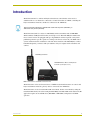
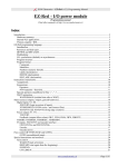
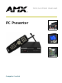
The PC Presenter (FIG. 1) consists of a TXC-MS(L) wireless transmitter and an AXR-MSE
Wireless Mouse and Keyboard Controller (receiver/processor). The TXC-MS(L) transmitter has
mouse controls and can be equipped with up to 24 pushbuttons with an engraved overlay. Each
pushbutton performs a specific operation according to the Axcess software in your AMX control
system, and the mouse disc and buttons control PC mouse functions. The TXC-MS(L)'s cordless
hand-held design lets you interact with your audience and your computer with convenience and
comfort.
TXC-MS(L) transmitter
AXR-MSE Wireless Mouse and Keyboard
Controller (receiver/processor)
FIG. 1 PC Presenter - transmitter and receiver units
The PC Presenter can be used in stand-alone or AXlink mode. The PC Presenter can control a PC
keyboard and mouse functions, plus any devices connected to the AXlink bus.
The PC Presenter can also be used in RF or IR control mode. Set the control mode by setting the
transmitter DIP switch (refer to the Setting the TXC-MS(L) transmitter DIP switch subsection). IR
applications require an external IR sensor (IRX-DM+ or IRX-SM+) configured for 455 KHz
operation.
PC Presenter
1
Introduction
TXC-MS(L) Specifications
Dimensions (HWD)
8.50" x 2.00" x 1.56" (21.59 cm x 5.08 cm x 3.96 cm)
Power
3.0 VDC (two AA alkaline batteries - supplied)
Enclosure
Molded black matte plastic
DIP switch
8-position sets IR or RF mode and radio mode
Pushbuttons
Up to 26 pushbuttons (with custom overlay)
Mouse controls
• 16-position mouse disc (two speeds), left and right mouse buttons
• Trigger switch operates left mouse button on TXC-MS
Range
• RF: 1-way @ 200 ft (60.96 m) and 2-way @ 500 ft. (152.40 m)
• IR: 30 ft (9.14 m)
Range
• IR: 455 KHz
• RF: 418 MHz standard (315 MHZ and 433.9 MHz available)
Weight
• 0.35 lbs (0.16 kg)
Included accessories
• Blank overlay
• 0.25 lbs (0.11 kg)
• 2 AA alkaline batteries
Optional accessories
• Custom logos
• Color text and borders on engraved overlay
• Multiple engraved overlay colors
• Laser pointer on TXC-MSL (L - laser pointer)
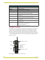
TXC-MS(L) Transmitter
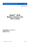
The TXC-MS(L) is an ergonomically designed pushbutton transmitter with up to 26 pushbuttons,
an optional laser trigger (TXC-MSL only), and PC mouse disc. The pushbuttons activate PC
functions or Axcess Push_Commands via infrared (IR) or radio frequency (RF) transmission.
FIG. 2 shows the PC Presenter transmitter and factory pushbutton configuration. A DIP switch
located in the battery compartment sets the transmitter for either RF or IR control. For information
on setting the TXC-MS(L) for RF or IR control, refer to the Setting the TXC-MS(L) transmitter
DIP switch subsection.
Pushbuttons
Left mouse
button
Overlay (blank is standard)
Right mouse button
pushbutton
Mouse disc
Pushbutton
Pushbuttons
Overlay (blank is standard)
FIG. 2 TXC-MS(L) mouse controls and 24 pushbutton locations
2
PC Presenter
Introduction
TXC-MS(L) controls
The TXC-MS(L) is available in configurations with up to 26 pushbuttons and PC mouse controls
(mouse disc and left and right mouse buttons). The TXC-MS(L) includes a custom engraved
overlay with text as desired by the customer.
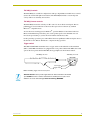
TXC-MS(L) mouse controls
The TXC-MS(L) mouse disc affords you 360° control of cursor direction and speed. The two
pushbuttons located on either side of the mouse disc replace those found on any standard
Microsoft® compatible mouse.
To slow the mouse tracking speed, in Windows®, open the Windows Control Panel and select
Mouse. In the Mouse Properties dialog box, set the pointer speed to near minimum. You can
increase the speed setting as you become more familiar with the mouse disc.
For drag-and-drop operations, press and hold the left mouse pushbutton while moving the cursor to
the desired location. Release this button to complete the drag operation.
Trigger switch
TXC-MS and TXC-MSL transmitters have a trigger switch on the underside of the transmitter
(FIG. 3). TXC-MSL transmitters are equipped with a laser pointer. On the TXC-MSL, this switch
operates the laser pointer. On the TXC-MS, the trigger duplicates the left mouse button.
TXC-MS(L) front view
TXC-MS(L) side view
Laser trigger
Trigger switch
FIG. 3 TXC-MS(L) trigger switch and laser pointer
Radiation Hazard: Lasers produce light emissions that are harmful to the human
eye. DO NOT look into or shine a laser beam into another person's eyes. Laser
radiation can cause retina damage. Read the following WARNING.
PC Presenter
3
Introduction
FIG. 4 Laser Radiation warning
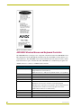
AXR-MSE Wireless Mouse and Keyboard Controller
The AXR-MSE is the receiver/processor component of the PC Presenter. The AXR-MSE receives
RF or IR signals from the TXC-MS(L) transmitter using the attached RF receiving antenna or an
external IR sensor. The AXR-MSE connects between the PC keyboard and mouse cables, and the
keyboard and mouse ports on the PC CPU. The AXR-MSE uses a standard four-pin captive wire
AXlink connector to connect to an AMX Central Controller.
AXR-MSE Specifications
Dimensions (HWD)
• 1.86" x 5.63" x 4.06" (4.72 cm x 14.29 cm x 10.31 cm)
• Height with antenna: 5.49" (13.96 cm)
• Depth with connectors - 4.06" (4.47 cm) and with antenna - 5.12" (13.00 cm)
Power
65 mA (max draw) @ 12 VDC
Enclosure
Metal with black matte plastic
Receive frequency
RF: 418 MHz standard (other frequencies are available)
Front Panel
AXlink
Green LED indicates AXlink communication as follows:
• Off indicates no power or the controller is not functioning properly
• One Blink per Second indicates normal operation. Device numbers match the
programmed device numbers in the Axcess program on the master.
• Full On indicates that there is no AXlink activity.
4
DIP switch
8-position sets the AXlink device ID
MOUSE LED
Red LED indicates mouse data transmission activity
KEYBOARD LED
Red LED indicates keyboard data transmission activity
DATA LED
Red LED indicates RF or IR signal reception
PC Presenter
Introduction
AXR-MSE Specifications (Cont.)
Rear Panel
TNC RF antenna
Accepts the flexible RF receiving antenna (up to 6 feet of RG-58 coax cable for
remote antenna set up can also be used).
KEYBOARD IN/OUT
Two PS/2 style keyboard connectors are used to connect the AXR-MSE to the
PC keyboard and CPU. The top connector, labeled "TO PC" connects the
AXR-MSE to the CPU with a PS/2 style cable (included). Plug the PC keyboard
into the bottom connector.
MOUSE IN/OUT
Two PS/2 style mouse connectors are used to connect the AXR-MSE to the PC
mouse and CPU. The top connector, labeled "TO PC" connects the AXR-MSE
to the CPU with a PS/2 style cable (included). Plug the PC mouse into the
bottom connector.
External IR Sensor
connector
4-pin data/power captive-wire is used to connect an optional external IR sensor
(for IR applications).
AXlink connector
4-pin data/power captive-wire.
Power connector
Optional 2-pin +12V power captive-wire.
Included accessories
• 800 mA power supply @ 12 VDC
• Two PS/2-style cables, male to male (6 ft.)
• Two 4-pin captive-wire connectors (for AXlink and IR sensor)
• One 2-pin captive-wire connector (for power)
Optional accessories
• 315 MHz and 433.9 MHz RF frequencies are available
• External IR sensor
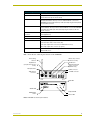
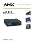
FIG. 5 shows the rear and front panel features of the AXR-MSE.
RF receiving
antenna
Mouse out (to mouse
connector on PC)
PC Mouse in
Keyboard out
(to keyboard connector
on PC)
Optional external IR
sensor connector
(455 KHz only)
PC Keyboard in
ANTENNA
KEYBOARD
MOUSE
EXTERNAL
IR SENSOR
+12VDC
PWR
AXlink
GND
AXP
AXM
GND
GND
PWR
TO
PC
IR IN
TNC antenna
connector
AUX
AXlink connector
+12VDC connector
PWR
IN
Data LED
AXlink
DEVICE
MOUSE
KEYBOARD
DATA
ON
AXlink LED
DEVICE DIP
switch
Keyboard LED
Mouse LED
FIG. 5 AXR-MSE rear and front panel features
PC Presenter
5
Introduction
6
PC Presenter
Pre-Installation
Pre-Installation
Setting the TXC-MS(L) transmitter DIP switch
The TXC-MS(L) transmitter transmits IR or RF signals, according to how you set position 1 on the
8-position DIP switch. The DIP switch is located under the battery cover, on the back of the
TXC-MS(L), as shown in FIG. 6. To open the battery compartment, slide the cover down and
remove.
8-position DIP switch
Battery compartment
FIG. 6 Location of 8-position DIP switch and battery compartment locations
FIG. 7 shows the eight-position transmitter DIP switch.
DIP switches
#2 - 4 are not used
DIP switch #1
sets IR or RF
transmission
DIP switches
#5 - 8 set the radio
code of the transmitter
FIG. 7 Eight-position transmitter DIP switch
IR and RF Settings
The transmitter can be configured for either IR or RF, but not both. DIP switch position 1 sets the
transmitter for IR or RF, as shown in FIG. 8.
IR mode
RF mode
FIG. 8 DIP switch settings for IR and RF modes
Set position 1 to Off (down) for IR.
Set position 1 to On (up) for RF.
PC Presenter
7
Pre-Installation
Radio Code Settings
Each pushbutton on the TXC-MS(L) transmitter represents an Axcess channel number. All of the
pushbuttons on the transmitter represent a group of channel numbers. This grouping is known as a
radio code. Use the transmitter DIP switch to assign a unique radio code to this transmitter. Radio
codes are important in applications that use more than one transmitter, because each transmitter
must be assigned its own unique radio code. This is necessary to avoid interference between two or
more transmitters.
The radio code is set with the last four positions on the eight-position transmitter DIP switch (see
FIG. 7 on page 7). After the radio code is set on the transmitter, each button you press sends a
specific channel number to the control system. For example, if your TXC-MS(L) transmitter is set
to radio code 4 and you press button 1, channel number 64 is sent to the control system.
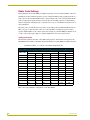
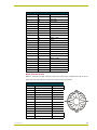
Setting radio codes
The following table lists the radio codes, DIP switch positions, and channel code ranges for the
TXC-MS(L). The formula to determine the channel number of a TXC-MS(L) transmitter button is:
(Pushbutton number - 1) + (Radio code number multiplied by 16).
TXC-MS(L) radio codes, DIP switch settings, and channel code ranges
DIP switch positions
Radio codes
5
6
Channel code ranges
7
8
From
To
1
ON
OFF
OFF
OFF
16
45
2
OFF
ON
OFF
OFF
32
61
3
ON
ON
OFF
OFF
48
77
4
OFF
OFF
ON
OFF
64
93
5
ON
OFF
ON
OFF
80
109
6
OFF
ON
ON
OFF
96
125
7
ON
ON
ON
OFF
112
141
8
OFF
OFF
OFF
ON
128
157
9
ON
OFF
OFF
ON
144
173
10
OFF
ON
OFF
ON
160
189
11
ON
ON
OFF
ON
176
205
12
OFF
OFF
ON
ON
192
221
13
ON
OFF
ON
ON
208
237
14
OFF
ON
ON
ON
224
253
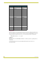
FIG. 9 shows the pushbutton configuration of the TXC-MS(L).
8
PC Presenter
Pre-Installation
1
8
15
2
9
16
3
10
17
25
24
27
30
29
28
26
4
11
18
5
12
19
6
13
20
7
14
21
22
23
FIG. 9 TXC-MS(L) pushbutton configuration
Setting the Device DIP switch
The eight-position Device DIP switch located on the front panel of the AXR-MSE as shown in
FIG. 10 sets the AXlink device number for the AXR-MSE. Each device on the AXlink bus must
have a unique AXlink device number.
AXlink
DEVICE
MOUSE
KEYBOARD
DATA
ON
Device DIP switch
FIG. 10 AXR-MSE device DIP switch
If you later change the device number, remove and reconnect the AXlink connector.
This enters the new device number into memory.
PC Presenter
9
Pre-Installation
The device can be 1 of the 255 devices in an Axcess, Axcent, Axcent2, Axcent3, AXB-MPE, or
AXB-EM232 system. The device number must match the device assignment in the Axcess
program. AMX assigns device numbers into the following three segments:
Cards - 1 through 95
Boxes - 96 through 127
Panels - 128 through 255
The device number takes effect only on power-up.
Set the device number by setting the device DIP switch. The device number is the total of all of the
switches in the ON (down) position. The following table shows the switch numbers and their
corresponding values.
Device DIP switch
positions and values
Position
Value
1
1
2
2
3
4
4
8
5
16
6
32
7
64
8
128
As an example, the following DIP switch settings define the AXR-MSE as device number 97
(1 + 32 + 64 = 97).
The AXR-MSE can operate without a keyboard. When the unit powers up it checks to
see if there is a keyboard attached. If there is not, the unit resets (approx. 5 sec. later)
and boots into a mode where it never checks the external keyboard again. You have
to cycle power in order for the keyboard to be recognized.
Using the PC Presenter Without a PC Computer
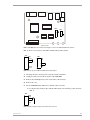
You may want to use the AXR-MSE without a PC computer in certain applications. To use the
AXR-MSE and a keyboard without the PC attached, you must set the AXR-MSE's internal slide
switches. The internal switches are located on the circuit card inside the MSE enclosure, as shown
in FIG. 11.
10
PC Presenter
Pre-Installation
SW3
SW2
Top front view
FIG. 11 AXR-MSE internal circuit board showing the location of the SW2 and SW3 slide switches
FIG. 12 shows a close-up view of the SW2 and SW3 internal slide switches.
SW3
PS2
mouse
SW2
Serial
mouse
NO
PC
PC
FIG. 12 Close-up view of SW2 and SW3 internal slide switches
1. Discharge the static electricity from your body and the screwdriver.
2. Unplug all connectors from the rear panel of the AXR-MSE.
3. Remove the four Phillips-head screws on the sides of the enclosure.
4. Remove the cover.
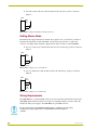
5. Set the AXR-MSE switch SW2 for use without a CPU as follows:
For keyboard use without a PC, slide the SW2 switch to the "NO PC" position shown in
FIG. 13.
SW2
NO
PC
PC
FIG. 13 Switch setting for keyboard use without PC connected
PC Presenter
11
Pre-Installation
For keyboard use with a PC, slide the SW2 switch to the "PC" position as shown in
FIG. 14.
SW2
NO
PC
PC
FIG. 14 Switch setting for keyboard use with PC connected
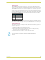
Setting Mouse Mode
The PC Presenter supports PS2 mice by default. If you prefer to use a serial mouse you must set
internal slide switch SW3 for this mode (FIG. 15). Serial mice typically have a 9 pin D-sub
connector. An adapter will be required to plug it into the mouse connector on the AXR-MSE.
For use a serial mouse, slide the SW3 switch to the "serial mouse" position as shown in
FIG. 15:
SW3
PS2
mouse
Serial
mouse
FIG. 15 Switch setting for use of a serial mouse
For use a PS2 mouse, slide the SW3 switch to the "PS2 mouse" position as shown in
FIG. 16:
SW3
PS2
mouse
Serial
mouse
FIG. 16 Switch setting for use of a PS2 mouse
Wiring Requirements
The AXR-MSE uses a four-pin AXlink connector for power and data. If the distance between the
AXR-MSE and the Central Controller exceeds power consumption limits, you must connect the
included 12 VDC power supply to the AXR-MSE's two-pin PWR connector.
Do not connect power to the AXR-MSE until the wiring is complete. If you are using a
12 VDC power supply, apply power to the AXR-MSE only after installation is
complete.
12
PC Presenter
Pre-Installation
Wiring guidelines
The AXR-MSE requires 65 mA @ 12 VDC power to operate properly. The Central Controller
supplies power via the AXlink cable. The maximum wiring distance between the Central Controller
and AXR-MSE is determined by power consumption supplied voltage, and the wire gauge used for
the cable. The following wiring guidelines table lists wire sizes and the maximum lengths allowable
between the AXR-MSE and the Central Controller. The maximum wiring lengths for using AXlink
power are based on a minimum of 13.5 volts available at the Central Controller's power supply.
Wiring Guidelines
Wire size
Maximum wiring length
18
1805.70 ft (550.37 m)
20
1142.40 ft (382.20 m)
22
712.20 ft (217.07 m)
24
448.90 ft (136.82 m)
If the AXR-MSE is installed farther away from the control system than recommended in the above
table, connect a 12 VDC power supply to the two-pin 12 VDC PWR IN connector on the rear panel.
Preparing captive wires
You will need a wire stripper, a soldering iron, solder, and a flat-blade screwdriver to prepare and
connect the captive wires.
1. Strip 0.25 inch (0.64 cm) of wire insulation off all wires.
2. Insert each wire into the appropriate opening on the connector according to the wiring
diagrams and connector types described in this section.
3. Turn the flat-head screws clockwise to secure the wire in the connector.
Do not over-torque the screw. Doing so can bend the seating pin and damage the
connector.
PC Presenter
13
Pre-Installation
14
PC Presenter
Installing the PC Presenter
Installing the PC Presenter
This section describes how to connect the AXR-MSE to the PC and to the Central Controller.
Before installation, check to verify that the Device DIP switch on the front panel of the AXR-MSE
is set correctly. Setting the Device DIP switch is described in the previous section (Setting the TXCMS(L) transmitter DIP switch section on page 7).
The PC Presenter can be set up for either stand-alone operation, or connected to a Central
Controller via AXlink for system-wide control. The following sections describe both set-up
scenarios.
Installing the PC Presenter for Stand Alone Operation
To use the PC Presenter as a stand-alone unit (not connected to AXlink), connect the AXR-MSE to
the PC keyboard and mouse. As a stand alone unit, the PC Presenter controls PC keyboard and
mouse functions. The following sub-sections describe connecting the PC Presenter for stand-alone
operation.
The PC Presenter uses PS/2 style mouse and keyboard connectors.
Step 1: Connecting the AXR-MSE to the PC keyboard and PC
To connect the AXR-MSE to the PC keyboard and PC:
1. Turn off your PC.
2. Disconnect the PC keyboard from the CPU.
3. Connect the PC keyboard cable to the bottom KEYBOARD connector on the rear panel of the
AXR-MSE.
4. Using the supplied keyboard cable, connect the keyboard connector on the CPU to the top
KEYBOARD connector on the AXR-MSE (labeled TO PC).
Step 2: Connecting the AXR-MSE to the PC mouse and PC
To connect the AXR-MSE to the PC mouse and PC:
1. Turn off your PC.
2. Disconnect the PC mouse from the CPU.
3. Connect the PC mouse cable to the bottom MOUSE connector on the rear panel of the
AXR-MSE.
4. Using the supplied mouse cable, connect the mouse connector on the CPU to the top MOUSE
connector on the AXR-MSE (labeled TO PC).
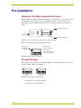
Step 3: Connecting an optional external IR sensor to the AXR-MSE
The AXR-MSE uses an optional external IR sensor to receive IR signals from the TXC-MS(L). To
connect an external IR sensor to the AXR-MSE, connect one or more optional IRX-SM+
swivel-mount IR receivers or IRX-DM+ IR receivers to the AXR-MSE as shown in FIG. 17.
PC Presenter
15
Installing the PC Presenter
G
N
D
G
N
D
R
I
N
E
x
t
e
r
n
a
l
I
R
S
e
n
s
oI
O
u
t
p
u
t
o
n
A
X
R
M
S
E
A
U
X
R
X
S
M
+
o
r
O
U
T I
M
+
I
R
X
D
X
O
U
T
A
U
P
W
R
+
1
2
V
FIG. 17 IRX-SM+ or IRX-DM+ external IR sensor wiring diagram
Installing the PC Presenter for AXlink Operation
To use the PC Presenter as an integrated AXlink device, connect the AXR-MSE to the PC
keyboard/mouse and a Central Controller. As an AXlink device, the PC Presenter controls PC
keyboard/mouse functions as well as the devices on the AXlink bus.
To connect the PC Presenter for AXlink operation, follow the instructions listed under Step 1, Step
2 and Step 3 starting on page 15 to connect the PC keyboard, mouse and optional external IR
receiver. The following sections describe connecting AXlink for power and data, and connecting an
optional external 12VDC power supply.
Using AXlink for data and power
Connect the Central Controller's AXlink connector (male) on the rear panel of the AXR-MSE for
data and 12 VDC power, as shown in FIG. 18.
P
W
R
(
+
)
A
X
R
M
S
E
P
W
R
A
X
P
A
X
P
X
M
A
A
X
M
N
D
G
G
N
D
C
e
n
t
r
a
lC
o
n
t
r
o
lle
r
A
X
lin
k
c
o
n
n
e
c
t
o
r
FIG. 18 IAXlink data and power wiring diagram
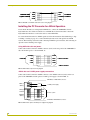
AXlink data and 12 VDC power supply connections
Connect the Central Controller's AXlink connector to the AXlink connector (male) on the rear
panel of the AXR-MSE, and the optional 12 VDC power supply as shown in FIG. 19.
AXB-IRS4, 12 VDC PWR connector
PWR (+)
GND (-)
12 VDC power supply
PWR(+)
PWR
AXP/TX
AXP
AXM/RX
AXM
GND (-)
GND
Control system
AXB-IRS4, AXlink/RS232 connector
FIG. 19 IAXlink and optional 12 VDC power supply wiring diagram
16
PC Presenter
Installing the PC Presenter
Make sure to connect only the GND wire on the AXlink connector when using a 12 VDC power
supply. Do not connect the PWR wire to the AXlink connector's PWR opening.
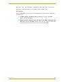
LED indicators
When the AXR-MSE is powered up, the front panel LEDs light to indicate the status of the unit as
described below:
All LED's lighting sequentially from left to right indicates that the AXR-MSE
firmware is loaded and running.
Blinking pattern that alternates between the Mouse + Data LED's and the Keyboard
LED indicates that the AXR-MSE is running on boot code only, and has no downloaded
program. You must download program code to operate the AXR-MSE.
PC Presenter
17
Installing the PC Presenter
18
PC Presenter
Programming the PC Presenter
Programming the PC Presenter
This section describes how to program the PC Presenter. Before programming, make sure the PC
Presenter is properly installed:
Verify that the PC keyboard and mouse are connected to the AXR-MSE, and the
AXR-MSE is connected to the keyboard and mouse ports on the CPU.
Device DIP switch settings (on the front panel of the AXR-MSE) match the device
number assigned to it in the Axcess program.
There are two primary ways to use the PC Presenter: Stand-alone operation (not connected to
AXlink), and AXlink operation. In stand-alone mode, the PC Presenter controls PC keyboard and
mouse functions. Connected to a Central Controller via AXlink, the PC Presenter can control
devices on the AXlink bus.
For information on installing the PC Presenter, refer to the Installing the PC Presenter for AXlink
Operation section.
Programming the PC Presenter in Stand Alone Mode
The PC Presenter has two modes of programming in stand-alone mode: command mode, in which
you give specific commands to the PC Presenter, and programming mode, in which you assign
specific PC keystrokes to pushbuttons on the transmitter.
Using PC Presenter Commands
The PC Presenter has a set of six commands that allow you to clear the PC Presenter memory, list
the commands, list the keycodes stored in PC Presenter memory (in both short and long form),
display the amount of memory available in the PC Presenter, and display firmware version and
copyright information.
To use the PC Presenter commands:
1. Begin at a DOS prompt on the PC that is connected to the AXR-MSE.
2. At the DOS prompt, enter program mode by selecting and holding the following keys on the
PC keyboard:
CTRL, then ALT then "." (period key).
For PC keyboards with left and right <Ctrl> and <Alt> keys, only the left<Ctrl><Alt> "."
combination will work.
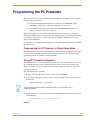
3. When these keys are released, program mode will be indicated by the following characters at
the DOS prompt:
C:\>rem Press command key or transmitter button
C:\>rem
PRGM EX. 1
PC Presenter
19
Programming the PC Presenter
The characters "C:\>rem" before the blinking cursor indicates that the PC Presenter is in
program mode, waiting for a command key.
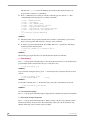
4. Press a command key. For a listing of available commands, type the character "H". This
command displays the following list of available commands:
C:\>rem c Commands Available
C:\>rem c : Clear memory
C:\>rem h : List commands (Help)
C:\>rem l : Short form listing of keycodes
C:\>rem m : Display available memory
C:\>rem t : Long form list of stored keycodes (Type)
C:\>rem v : Display version and copyright info
C:\>
C:\> rem Exiting program/command mode
C:\>
PRGM EX. 2
5. The PC Presenter exits program/command mode each time a command key is pressed. You
must re-enter program/command mode to enter any of the commands.
6. To return to program/command mode, press CTRL, ALT, and "." (period) keys. This brings
back the program/command syntax:
C:\>rem Press command key or transmitter button
C:\>rem
PRGM EX. 3
The following paragraphs describe each of the PC Presenter keyboard commands.
C - Clear memory
Press "C" at the program/command prompt to clear the PC Presenter memory of all commands and
programmed keystrokes. PC Presenter asks you to verify this action:
C:\>rem Clear memory (y/n)
PRGM EX. 4
To proceed with clearing the memory, press "Y". PC Presenter tells you that the memory has been
cleared:
C:\>rem Clear memory (y/n)y
C:\>rem Clearing Memory
**Done**
PRGM EX. 5
To abort this command, press "N". PC Presenter tells you that the command has been aborted:
C:\>rem Clear memory (y/n)n Aborted
PRGM EX. 6
H - List commands (Help)
Press "H" at the program/command prompt to display the list of PC Presenter keyboard commands.
L - Short form listing of keycodes
Press "L" at the program/command prompt to display a listing of the keycodes currently saved in
PC Presenter memory, in short form. A short form listing of keycodes contains the button code
number and the size of the saved keycode. For example:
20
PC Presenter
Programming the PC Presenter
C:\>rem Code : 128
C:\>rem Code : 129
C:\>rem Code : 130
Size : 24 bytes
Size : 24 bytes
Size : 24 bytes
PRGM EX. 7
M - Display available memory
Press "M" at the program/command prompt to display the amount of memory available in the PC
Presenter:
C:\>rem Memory available : 60436 bytes
PRGM EX. 8
T - Long form list of stored keycodes
Press "T" at the program/command prompt to display a listing of the keycodes currently saved in
PC Presenter memory, in long form. A long form listing of keycodes contains the button code
number, the size of the saved keycode, and the keystrokes recorded. The following example
represents the keycode "Button 1" on button 128:
C:\>rem Code : 128
Size : 24 bytes
C:\>rem 32 F0 32 3C F0 2C 2C F0 2C 44 F0 44 31
PRGM EX. 9
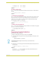
V - Display version and copyright info
Press "V" at the program/command prompt to display the firmware version number, and copyright
information, as shown in the example below:
C:\>rem Firmware version x1.001
C:\>rem Copyright AMX Corporation 2000
PRGM EX. 10
Programming Transmitter Pushbuttons
The program the transmitter pushbuttons.
1. Begin at a DOS prompt on the PC that is connected to the AXR-MSE.
2. At the DOS prompt, enter program mode by selecting and holding the following keys on the
PC keyboard:
CTRL, then ALT then "." (period key).
For PC keyboards with left and right <Ctrl> and <Alt> keys, only the left<Ctrl><Alt> "."
combination will work.
3. When these keys are released, program mode will be indicated by the following characters at
the DOS prompt:
C:\>rem Press command key or transmitter button
C:\>rem
PRGM EX. 11
The characters "C:\>rem" before the blinking cursor indicate that the PC Presenter is in
program mode, waiting for a command key.
PC Presenter
21
Programming the PC Presenter
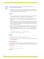
All PC Presenter programming is retained in the PC Presenter's non-volatile memory.
It is not lost during power down or shipping.
4. Press the first transmitter button to be programmed. When the button is pressed, the button's
code number and an asterisk (*) appear at the DOS prompt. The following example shows that
the transmitter button (code number 128) was pressed.
C:\>rem (128)*
PRGM EX. 12
The asterisk after the button code number indicates that the PC Presenter is in programming
mode, waiting for keystrokes to be assigned to the selected transmitter button.
5. Type the keystrokes that are to be executed by the corresponding transmitter button. For
example, type Button One. The characters that you type are displayed on the screen as you
type them.
To cancel a keystroke entry error, press a different radio transmitter button than the one used to
initiate the current keystroke assignment. If you press a different button after keystrokes are
entered, no changes are saved. This action cancels the new keystroke assignment, and the PC
Presenter remains in program mode.
6. Press the same radio transmitter button (the button pressed in step 4 a second time. This action
displays a second asterisk ("*") immediately after the recorded keystrokes, the transmitter
button's code number, and the message "*** Keystrokes saved ***". The example below
shows that the transmitter button (code number 128) was programmed with the keystrokes
"Button One".
C:\>rem (128)*Button One*(128)
**Keystrokes saved**
C:\>rem Press transmitter button to store next radio code or
C:\>rem press any key on keyboard to exit
C:\>
C:\>rem
PRGM EX. 13
The PC Presenter remains in program mode until you tell it to exit
7. Repeat steps 4-6 to assign keystrokes to other buttons, or to change keystroke assignments for
any programmed button.
Exiting program mode
To exit program mode, press any key on the PC keyboard. PC Presenter tells you that it is storing
the new codes and keystrokes, when it is finished saving, and then that it is exiting program mode,
as shown below:
C:\>rem Storing codes and keystrokes
C:\>rem Done
C:\>
C:\> rem Exiting program/command mode
PRGM EX. 14
22
PC Presenter
Programming the PC Presenter
Programmed keystrokes are not saved in permanent memory until program mode is
exited.
Programming the PC Presenter for Use With an Axcess
Central Controller
The PC Presenter can be connected to a Central Controller via AXlink, to control devices on the
AXlink bus. The following sub-sections describe the Axcess commands for the PC Presenter.
Creating a buffer for keyboard input
To recognize keyboard keystrokes in an Axcess program, you must create a buffer for the device in
Axcess. To create a buffer, use the CREATE_BUFFER keyword. This keyword can only be placed
in the DEFINE_START section of your program. The syntax is shown below:
CREATE_BUFFER <DEVICE> <ARRAY>
PRGM EX. 15
Standard keystrokes fill the buffer as ASCII characters. Special characters come in as their
embedded code equivalents as shown in the Send_Strings table on page 24 of this manual, in the
Send_Strings subsection. For more information on using buffers, refer to the Axcess Programming
Guide.
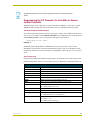
Send_Commands
Use the Send_Commands listed in the following table to program the Axcess Control System and
the PC Presenter. Refer to the Axcess Programming Guide for additional programming information.
Send_Commands
Command
Description
'CLRM'
Clears permanent keystroke macro memory.
'DCODEOFF'
Disables AXlink Channel Codes from mouse disc.
'DCODEON'
Enables AXlink Channel Codes from mouse disc (default).
'IROFF'
Disables IR reception.
'IRON'
Enables IR reception (default).
'KBOFF'
Disables keystrokes from attached keyboard to PC.
'KBON'
Enables keystrokes from attached keyboard to PC (default).
'PMACRO<n>'
Invokes playback of keystroke macro for channel code n.
<n> = ASCII number from 1 to 255.
'MOUSEOFF'
Disables mouse control from TXC-MS(L) to PC.
'MOUSEON'
Enables mouse control from TXC-MS(L) to PC (default).
'MSPEED<S>'
Set speed of TXC-MS(L) mouse disc.
<s> = ASCII number from 1 to 16 (default = 4)
'P<n>R<s>'
Set speed number n to value s (for AXlink channel mouse control).
<n> = ASCII '1' or '2'
<s> = ASCII number from 0 to 255
PC Presenter
23
Programming the PC Presenter
Send_Commands (Cont.)
Command
Description
'REPEATOFF'
Disables macro repeat when holding transmitter button.
'REPEATON'
Enables macro repeat when holding transmitter button (default).
'RMACRO<n>-<s>'
Records strings in keystroke macro memory under channel code n.
<n> = ASCII number 1 to 255
<s> = ASCII string
'RFOFF'
Disables RF reception.
'RFON'
Enables RF reception (default).
'TXID<n>'
Sets the transmitter ID, for mouse disc only. Only TXC-MS(L) with the radio
code set to n will be recognized.
<n> = ASCII number 0 to 16.
• Set <n> from 0 to 15 for specific radio codes.·
• Set <n> to 16 to enable mouse disc control from all radio codes (default).
This parameter is stored in memory even if the unit is powered down.
'XINVERT'
Reverses the direction the PC's cursor moves horizontally in response to
AXLink levels. This parameter is stored in memory even if the unit is powered
down.
'YINVERT'
Reverses the direction the PC's cursor moves vertically in response to AXLink
levels. This parameter is stored in memory even if the unit is powered down.
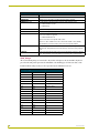
Send_Strings
All received Send_Strings are translated to keystrokes and output to the attached PC's keyboard
port. The following table represents the embedded codes defining special characters that can be
included with the string but may not be represented by the ASCII character set.
Send_Strings
24
Decimal
Hexadecimal
Keystroke
8
$08
BACKSPACE
13
$0D
ENTER
27
$1B
ESC
128
$80
CTRL key down
129
$81
ALT key down
130
$82
SHIFT key down
131
$83
F1
132
$84
F2
133
$85
F3
134
$86
F4
135
$87
F5
136
$88
F6
137
$89
F7
138
$8A
F8
139
$8B
F9
140
$8C
F10
141
$8D
F11
PC Presenter
Programming the PC Presenter
Send_Strings (Cont.)
Decimal
Hexadecimal
Keystroke
142
$8E
F12
143
$8F
NUM LOCK
144
$90
CAPS LOCK
145
$91
INSERT
146
$92
DELETE
147
$93
HOME
148
$94
END
149
$95
PAGE UP
150
$96
PAGE DOWN
151
$97
SCROLL LOCK
152
$98
PAUSE
153
$99
BREAK
154
$9A
PRINT SCREEN
155
$9B
SYSRQ
156
$9C
TAB
157
$9D
WINDOWS
158
$9E
MENU
159
$9F
UP ARROW
160
$A0
DOWN ARROW
161
$A1
LEFT ARROW
162
$A2
RIGHT ARROW
192
$C0
CTRL key up
193
$C1
ALT key up
194
$C2
SHIFT key up
Mouse Control Channels
While on, channels 1 through 32 will move the mouse cursor in one of 16 directions and one of two
speeds. The following table lists the direction and speed for each channel.
Mouse Control Channels
PC Presenter
Channel
Direction
Speed
1
North
@speed1
2
North/Northeast
@speed1
3
Northeast
@speed1
4
East/Northeast
@speed1
5
East
@speed1
6
East/Southeast
@speed1
7
Southeast
@speed1
8
South/Southeast
@speed1
9
South
@speed1
10
South/Southwest
@speed1
11
Southwest
@speed1
12
West/Southwest
@speed1
13
West
@speed1
25
Programming the PC Presenter
Mouse Control Channels (Cont.)
Channel
Direction
Speed
14
West/Northwest
@speed1
15
Northwest
@speed1
16
North/Northwest
@speed2
17
North
@speed2
18
North/Northeast
@speed2
19
Northeast
@speed2
20
East/Northeast
@speed2
21
East
@speed2
22
East/Southeast
@speed2
23
Southeast
@speed2
24
South/Southeast
@speed2
25
South
@speed2
26
South/Southwest
@speed2
27
Southwest
@speed2
28
West/Southwest
@speed2
29
West
@speed2
30
West/Northwest
@speed2
31
Northwest
@speed2
32
North/Northwest
@speed2
33
Left mouse button
34
Right mouse button
Using Levels
The mouse operates on an X-Y (horizontal-vertical) axis. Level one is the X-axis and level two is
the Y-axis. The range for both levels is 0-255. To send a level from the TXC-MS(L) to an Axcess
Central Controller, use the keyword CREATE_LEVEL in your Axcess program as shown below:
CREATE_LEVEL <device>, <1>, <x-pos>
CREATE_LEVEL <device>, <2>, <y-pos>
PRGM EX. 16
This allows the use of the TXC-MS(L) transmitter as a wireless joystick or as pointing device to
another unit.
For detailed information on Axcess programming and using levels, refer to the Axcess
Programming Guide.
26
PC Presenter
Using the OLDesign Engraving Program
Using the OLDesign Engraving Program
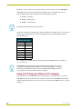
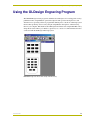
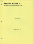
The AMX OLDesign software program is a Windows-based design tool for creating panel overlays,
pushbutton names, and pushbutton operation descriptions. The operation descriptions are used
when the Axcess operating software is programmed. OLDesign also contains an online help system
that describes producing custom overlay designs and pushbutton descriptions, and then storing
them on your computer. FIG. 20 shows the OLDesign main window and a sample TXC-MS overlay
design. Refer to the OLDesign for Windows Quick Reference Guide for command instructions that
can be used with the OLDesign online help system.
FIG. 20 OLDesign main window with example TXC-MS overlay
PC Presenter
27
Using the OLDesign Engraving Program
28
PC Presenter
TXC-MS(L) Battery Replacement
TXC-MS(L) Battery Replacement
The TXC-MS(L) transmitter uses two AA batteries. Under normal conditions, battery life will
exceed one year. Use alkaline batteries for long battery life and optimum performance.
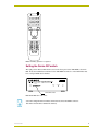
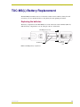
Replacing the batteries
The battery compartment of the TXC-MS(L) is located on the back of the transmitter (FIG. 21).
Slide the battery compartment cover off, and replace the two AA batteries.
TXC-MS(L) bottom view
AA batteries
Battery
compartment
cover
FIG. 21 TXC-MS(L) battery compartment
PC Presenter
29
brussels • dallas • los angeles • mexico city • philadelphia • shanghai • singapore • tampa • toronto* • york
3000 research drive, richardson, TX 75082 USA • 469.624.8000 • 800.222.0193 • fax 469.624.7153 • technical support 800.932.6993
046-004-1901 4/05 ©2005 AMX Corporation. All rights reserved. AMX, the AMX logo, the building icon, the home icon, and the light bulb icon are all trademarks of AMX Corporation.
AMX reserves the right to alter specifications without notice at any time. *In Canada doing business as Panja Inc.
AMX reserves the right to alter specifications without notice at any time.