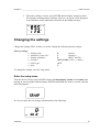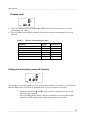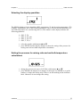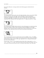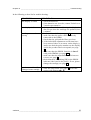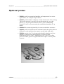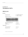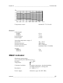
1
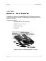
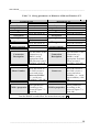
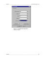
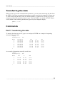
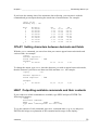
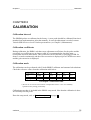
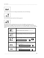
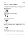
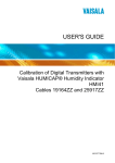
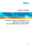
USER'S GUIDE ® Vaisala HUMICAP Set for Measuring Humidity in Concrete HM44 M010068EN-A PUBLISHED BY Vaisala Oyj P.O. Box 26 FIN-00421 Helsinki Finland Phone (int.): +358 9 8949 1 Fax: +358 9 8949 2227 Visit our Internet pages at http://www.vaisala.com/ © Vaisala 2006 No part of this manual may be reproduced in any form or by any means, electronic or mechanical (including photocopying), nor may its contents be communicated to a third party without prior written permission of the copyright holder. The contents are subject to change without prior notice. Please observe that this manual does not create any legally binding obligations for Vaisala towards the customer or end user. All legally binding commitments and agreements are included exclusively in the applicable supply contract or Conditions of Sale. _________________________________________________________________________________ Table of Contents CHAPTER 1 GENERAL INFORMATION ............................................................................3 Safety .........................................................................................3 Version Information..................................................................3 Warranty ....................................................................................4 CHAPTER 2 PRODUCT DESCRIPTION.............................................................................5 CHAPTER 3 TO BE NOTED WHEN MEASURING HUMIDITY ..........................................6 CHAPTER 4 TAKEN INTO USE ..........................................................................................7 Feeding the individual adjustment coefficients ....................7 Numbering the probes ......................................................8 Feeding the offset correction............................................8 Feeding the gain correction..............................................8 Changing the settings ..............................................................9 Enter the setup menu .......................................................9 Display units ...................................................................10 Setting the automatic power-off function........................10 Selecting the display quantities ......................................11 Setting the pressure for mixing ratio and wet bulb temperature calculations ................................................11 Setting the probe type ....................................................12 Select the function ..........................................................12 CHAPTER 5 HUMIDITY MEASUREMENTS IN CONCRETE ...........................................13 General about humidity measurements in a drilled hole ...13 Measurement depth................................................................13 Maximum humidity levels for coating ..................................15 Preparations for the measurements .....................................16 Starting the measurements ...................................................18 Measurement readings on display........................................19 HOLD-mode ........................................................................19 MIN and MAX modes ..........................................................19 VAISALA ___________________________________________________________________ 1 User's Guide _______________________________________________________________________ CHAPTER 6 COLLECTING DATA ................................................................................... 21 Data collecting modes........................................................... 21 Entering the data collecting modes..................................... 21 Automatic data collecting mode REC AUTO .......................... 22 Setting the measurement duration...................................... 22 Setting the measurement interval ....................................... 23 Manual data collecting REC CATCH ........................................ 24 Reading the measurement results REC READ ....................... 25 MIN and MAX in data collecting REC READ mode ................ 26 CHAPTER 7 TRANSFERRING DATA TO A PC .............................................................. 28 Giving the communication parameters ............................... 29 Transferring the data ............................................................. 31 Commands.......................................................................... 32 PLAY Transferring the data ............................................... 32 CPLAY Setting characters between decimals and fields... 33 HELP Outputting available commands and their contents 33 ? Outputting the HMI41 settings ........................................ 34 CHAPTER 8 CALIBRATION............................................................................................. 35 Two-point humidity calibration............................................. 37 CHAPTER 9 MAINTENANCE ........................................................................................... 39 Replacing the HUMICAP 180 sensor ................................. 39 Replacing the filter................................................................. 39 CHAPTER 10 TROUBLESHOOTING ................................................................................. 40 Erroneous readings............................................................. 40 Trouble shooting ................................................................. 40 CHAPTER 11 SPARE PARTS AND ACCESSORIES........................................................ 42 Optional probes...................................................................... 43 CHAPTER 12 TECHNICAL DATA...................................................................................... 44 HMP44 probe .......................................................................... 44 HMI41 indicator ...................................................................... 45 ______________________________________________________________________________ 2 Chapter 1 _________________________________________________________ General Information CHAPTER 1 GENERAL INFORMATION Safety Throughout the manual, important safety considerations are highlighted as follows: WARNING Warning alerts you to a serious hazard. If you do not read and follow instructions very carefully at this point, there is a risk of injury or even death. CAUTION Caution warns you of a potential hazard. If you do not read and follow instructions carefully at this point, the product could be damaged or important data could be lost. NOTE Note highlights important information on using the product. Version Information Table 1 Manual Code U254en-1.3 M010068en-A Manual Revisions Description March 1998 VAISALA ___________________________________________________________________ 3 User's Guide _______________________________________________________________________ Warranty Vaisala hereby represents and warrants all Products manufactured by Vaisala and sold hereunder to be free from defects in workmanship or material during a period of twelve (12) months from the date of delivery save for products for which a special warranty is given. If any Product proves however to be defective in workmanship or material within the period herein provided Vaisala undertakes to the exclusion of any other remedy to repair or at its own option replace the defective Product or part thereof free of charge and otherwise on the same conditions as for the original Product or part without extension to original warranty time. Defective parts replaced in accordance with this clause shall be placed at the disposal of Vaisala. Vaisala also warrants the quality of all repair and service works performed by its employees to products sold by it. In case the repair or service works should appear inadequate or faulty and should this cause malfunction or nonfunction of the product to which the service was performed Vaisala shall at its free option either repair or have repaired or replace the product in question. The working hours used by employees of Vaisala for such repair or replacement shall be free of charge to the client. This service warranty shall be valid for a period of six (6) months from the date the service measures were completed. This warranty is however subject to following conditions: a) A substantiated written claim as to any alleged defects shall have been received by Vaisala within thirty (30) days after the defect or fault became known or occurred, and b) The allegedly defective Product or part shall, should Vaisala so require, be sent to the works of Vaisala or to such other place as Vaisala may indicate in writing, freight and insurance prepaid and properly packed and labelled, unless Vaisala agrees to inspect and repair the Product or replace it on site. a) normal wear and tear or accident; b) misuse or other unsuitable or unauthorized use of the Product or negligence or error in storing, maintaining or in handling the Product or any equipment thereof; c) wrong installation or assembly or failure to service the Product or otherwise follow Vaisala service instructions including any repairs or installation or assembly or service made by unauthorized personnel not approved by Vaisala or replacements with parts not manufactured or supplied by Vaisala; d) modifications or changes of the Product as well as any adding to it without Vaisala's prior authorization; e) other factors depending on the Customer or a third party. Notwithstanding the aforesaid Vaisala's liability under this clause shall not apply to any defects arising out of materials, designs or instructions provided by the Customer. This warranty is expressly in lieu of and excludes all other conditions, warranties and liabilities, express or implied, whether under law, statute or otherwise, including without limitation ANY IMPLIED WARRANTIES OF MERCHANTABILITY OR OF FITNESS FOR A PARTICULAR PURPOSE and all other obligations and liabilities of Vaisala or its representatives with respect to any defect or deficiency applicable to or resulting directly or indirectly from the Products supplied hereunder, which obligations and liabilities are hereby expressly cancelled and waived. Vaisala's liability shall under no circumstances exceed the invoice price of any Product for which a warranty claim is made, nor shall Vaisala in any circumstances be liable for lost profits or other consequential loss whether direct or indirect or for special damages. This warranty does not however apply when the defect has been caused through ______________________________________________________________________________ 4 Chapter 2 _________________________________________________________ Product description CHAPTER 2 PRODUCT DESCRIPTION The HM44 set is a practical tool for humidity measurements of concrete or other structures. The accuracy and reliability performance of the HMP44 probe comes from advanced Vaisala HUMICAP© 180 sensor. The HM44 package includes: • HMP44 humidity and temperature probe • HMI41 indicator with batteries • installation cover and lid, 3 pcs • rubber plugs, 12 pcs • plastic sleeves, 12 pcs • carrying case • user's guide Figure 2.1 HM44 set for measuring humidity in concrete. VAISALA __________________________________________________________________________5 User's Guide _______________________________________________________________________ CHAPTER 3 TO BE NOTED WHEN MEASURING HUMIDITY Temperature of the probe and the concrete shall be the same! In humidity measurement and especially in calibration it is essential that temperature of the probe and measured object is the same. Even a small difference in temperature between the measured object and the probe causes an error. As the curve below shows, if the temperature is +20 °C and the relative humidity 100 %RH, a difference of ±1 °C between the measured object and the probe causes an error of ±6 %RH. When the humidity is 90 %RH, the corresponding error is ±5.4 %RH. A temperature difference of a few degrees can also cause water to condense on the sensor surface. HUMICAP sensor starts to function normally as soon as the water has evaporated. If the condensed water is contaminated, the life span of the probe may shorten and calibration may change. 10 9 8 dRH (%RH) 7 6 5 4 3 2 1 0 -40 -20 0 20 40 60 80 100 Temperature (°C) Figure 3.1 Measurement error at 100 %RH when the difference between the ambient and sensor temperature is 1 °C _________________________________________________________________________________ 6 Chapter 4 _____________________________________________________________ Taken into use CHAPTER 4 TAKEN INTO USE Before taking into use the HM44 do the following: - place the batteries into HMI indicator connect the probe feed the individual probe adjustment coefficients if needed, check and change the settings The basic display appears when turning the device on: RH % T °C Relative humidity Temperature Currently selected probe Feeding the individual adjustment coefficients Each probe has an individual adjustment coefficients which are written in the calibration certificate (see Appendix 1). These coefficients should be fed to the HMI41 memory to reach the measurement accuracy of ±2 %RH. - When using one probe, numbering of the probe is not needed. - When using more than one probe, firstly select a number for the probe and then feed the probe individual coefficients to the HMI41 memory. Remember to write the probe number (1-10) in the product label to be able to identify the probes afterwards. VAISALA __________________________________________________________________________7 User's Guide _______________________________________________________________________ Numbering the probes The first number of the second line of display indicates the currently selected probe (1-10). Connect a probe and change the number on the display by pressing ENTER and simultaneously buttons ▲ or ▼. Remember to write the probe number (1-10) in the product label to be able to identify the probes. Feeding the offset correction 1. Press the button ENTER continuously for about 5 seconds until a text similar to the following appears on the display (numbers on the second line are blinking): RH set 2. Feed the individual offset correction (see the calibration certificate) in the HMI41 memory with buttons ▲ and ▼. Each time the button is pressed, the numbers change 0.1 %RH. If the button is pressed continuously, the numbers change in a faster rate. 3. When the reading is correct, press ENTER and the display changes to show the gain correction. Feeding the gain correction RH set 4. NOTE Numbers on the second line are blinking; you can now enter the individual gain correction in the HMI41 memory. The numbers are changed with buttons ▲and ▼. Each time the button is pressed, numbers change 0.001. If the button is pressed continuously, the numbers change in a faster rate. If the correction given in the calibration certificate has only two decimals (e.g. 1.03), enter a zero in place of the third decimal (e.g. 1.030). _________________________________________________________________________________ 8 Chapter 4 _____________________________________________________________ Taken into use 5. When the reading is correct, press ENTER and the display changes to show the humidity and temperature readings. However, an arrow is now displayed as an indication of the individual corrections in the HMI41 memory: RH % T °C Changing the settings Change the settings ONLY if there is a need to change the following factory settings: Factory settings • • • • • • display units: automatic power-off: display quantities: pressure: probe type start 0 (metric) 5 (minutes) 0 (RH, T and Td) 1013.25 hPa (1 hPa = 1 mbar) AUT 5 To change the settings, enter the setup menu. Enter the setup menu Turn the device ON (by using ON/OFF button) and immediately (within 1..2 seconds) after turning on, press together both the buttons ENTER and MODE for about 3 seconds, until the following appears: In a few seconds, the text changes automatically to the following: °C set VAISALA __________________________________________________________________________9 User's Guide _______________________________________________________________________ Display units °C set • Select the display units with buttons ▲ or ▼. Choose 0 for metric units or 1 for non- metric units (see Table 1). • Press ENTER and the display changes to show the setting of the automatic power-off function. Table 1. Metric and non-metric units quantity relative humidity (RH) temperature (T) dewpoint temperature (Td) absolute humidity (a) mixing ratio (x) wet bulb temperature (Tw) metric %RH °C °C g/m3 g/kg °C non-metric %RH °F °F gr/ft3 gr/lb °F Setting the automatic power-off function set The number (or text NO) on the first line of the display indicates in minutes (1...60) the time that the HMI41 stays on before an automatic power-off if no buttons are pressed. • changed with buttons ▲ and ▼. If NO is chosen, the automatic power-off function is not activated. • Press ENTER and the display changes to show the selection of the display quantities. NOTE: during data collecting this setting is not valid. _________________________________________________________________________________ 10 Chapter 4 _____________________________________________________________ Taken into use Selecting the display quantities set The HMI41 displays relative humidity (RH), temperature (T) and dewpoint temperature (Td) readings. Additionally, one of the following quantities can be chosen: absolute humidity (a), wet bulb temperature (Tw) and mixing ratio (x). The number on the display indicates the following quantities: 0 = RH, T, Td 1 = RH, T, Td, abs 2 = RH, T, Td, Tw 3 = RH, T, Td, x • select the number with buttons ▲ and ▼ • press ENTER and the display changes to show the setting of the pressure for mixing ratio and wet bulb temperature calculations. Setting the pressure for mixing ratio and wet bulb temperature calculations P set hPa • change the pressure (in steps of 0.25 hPa) with buttons ▲ and ▼ • press ENTER; the display now changes to show the text PROBE n (n=probe number). Change this setting only if there is no ID-marking on the indicator label. Otherwise do not change this setting. VAISALA __________________________________________________________________________ 11 User's Guide _______________________________________________________________________ Setting the probe type In cases where an indicator (or a probe) is without an ID-marking, the following probe numbers have to be selected: Probe Probe setting HMP41 HMP42 HMP44 HMP45 HMP46 1 2 1...10 1 2 • change the setting with buttons ▲ and ▼ With the probe HMP44 there is no need to change the setting. • press ENTER; the display now changes to show the text START. Change this setting only if there is no ID-marking on the indicator label. Otherwise do not change this setting. Select the function In cases where an indicator (or a probe) is without an ID-marking on the label the following function selection is made: Probe HMP41 HMP42 HMP45 HMP46 HMP44 Setting Start 1 Start 5 • change the setting with buttons ▲ and ▼ • press ENTER three times; the display now changes to show the following settings (do not change them): baud seri calib 4.8 E.7.1 def (* (* when entering the setting calib, the value is always ‘no’; the factory settings are restored by selecting ‘def’. After this, the previously entered adjustment coefficients are no longer valid. _________________________________________________________________________________ 12 Chapter 5 ____________________________________________ Humidity measurements in concrete CHAPTER 5 HUMIDITY MEASUREMENTS IN CONCRETE General about humidity measurements in a drilled hole The HMP44 probe measures humidity of concrete in a drilled hole. In equilibrium stage, the humidity of a concrete and air humidity in a drilled hole become same. Drilling changes the stage of the concrete. This is due to the fact that heat is formed during drilling.(Meantime the humidity of the concrete changes, because of the temperature changes). To reach the equilibrium stage after drilling takes about three days. When the equilibrium stage has been reached, the air humidity in a drilled hole and the concrete humidity become equal. Then it is possible to make the humidity measurement. For getting more reliable results, it is recommended to have several measurement points. Measurement depth Depth of a drilled hole When drying of a concrete slab takes place from both sides, the minimum depth of measurement (d) is made 20 % of the depth of the slab. When drying occurs from one side only, the measurement depth (d ) is 40 % of the depth of a slab. See Figure 5.1. Humidity profile (Figure 5.1) The humidity profile of the slab depends on the drying of the concrete, i.e. whether the concrete dries in one or in two directions. In concrete slabs drying in two directions, the humidity is highest in the middle. After coating, the humidity spreads evenly throughout the VAISALA __________________________________________________________________________ 13 User's Guide _______________________________________________________________________ slab until it corresponds to readings measured at the depth of approximately 20% of the slab. In concrete slabs drying in one direction only, the humidity is highest at the bottom. After coating, the humidity spreads evenly throughout the slab until it corresponds to readings measured at the depth of approximately 40% of the slab. DRYING IN TWO DIRECTIONS coating hole for the plastic tube hole for the plastic tube humidity profile 0.2xd concrete slab d humidity profile 0.2xd concrete slab d AFTER COATING BEFORE COATING DRYING IN ONE DIRECTION coating hole for the plastic tube concrete slab hole for the plastic tube humidity profile 0.4xd d BEFORE COATING concrete slab humidity profile 0.4xd d AFTER COATING Figure 5.1 Humidity profile before and after the coating _________________________________________________________________________________ 14 Chapter 5 ____________________________________________ Humidity measurements in concrete Maximum humidity levels for coating SisäRYL 2000 Code of Building Practice (RT 14-10668, 2000, ISBN 951-682-506-0) recommends the following maximum humidity levels (at +20°C) for coating of various materials : Wooden floor coverings Maximum RH (%) Coating Wooden parquet boards without moisture barrier (plastic film) between wood and concrete. Enlaid wooden floor coverings. Floating wooden floor coverings with moisture barrier (plastic 801 film) between wood and concrete. 1 SisäRYL 2000 Code of Building practice, RT 14-10668, 2000, ISBN 951-682-506-0, page 332. 601 Other materials Maximum RH (%) 851 Coating Plastic floor coverings with fibre felt base or cellular plastic base Rubber floor coverings Cork tiles with moisture barrier (plastic film) Textile floor coverings with rubber, PVC or latex base Natural fibre textile floor coverings without base Plastic tiles Plastic floor coverings without felt or cellular plastic base Linoleum (Cork) Man-made fibre textile floor coverings without base structure Epoxy mass 97 Acrylic mass Polyester plastic mass 1 SisäRYL 2000 Code of Building practice, RT 14-10668, 2000, ISBN 951-682-506-0, page 318. 901 VAISALA __________________________________________________________________________ 15 User's Guide _______________________________________________________________________ Preparations for the measurements The holes shall be drilled 3 days before the measurements. A plastic sleeve and an installation cover are placed to the hole immediately after drilling. A probe can be placed to the plastic sleeve immediately after drilling or before measurements. Follow the instructions below. 1. 2. Bore 3 days before the measurements at least two holes with diameter of ∅ 16 mm and sufficient depth, see page 13. Clean the hole thoroughly e.g. by blowing air or with a vacuum cleaner. Press a plastic sleeve into the hole. If you need something to press it with, use e.g. the lid of the installation cover. Figure 5.1 Pressing the sleeve into the hole NOTE Make sure that the sleeve and the probe are not colder than the concrete during installation: this might cause condensation on the probe and the readings can be incorrect. 3. Close the hole by using an installation cover as described in the following or Press an installation cover on the plastic sleeve and make it slide down freely. Press the installation cover against the base so that the sealing presses down slightly. Turn the cover 90° to lock it in place. Figure 5.2.Locking the cover in place _________________________________________________________________________________ 16 Chapter 5 ____________________________________________ Humidity measurements in concrete 4. Insert the probe into the sleeve by feeding it in with the cable until it touches the bottom. Close a rubber plug around the cable and seal the sleeve with it: Figure 5.3 Sealing the sleeve with a plastic plug 5. Fold the cable in the installation cover and close the lid. Leave the probe to stabilize before starting the measurements. rubber plug lid probe cable probe plastic sleeve installation cover sealing § Figure 5.4 Cable folded in the installation cover Alternatively, you can insert the probe into the sleeve about 30 minutes before starting the measurements. In this case, close the cable lead-through of a rubber plug with its cap as shown in the photo, and seal the sleeve with the plug: VAISALA __________________________________________________________________________ 17 User's Guide _______________________________________________________________________ Figure 5.5 Close the cable lead-through of the rubber plug However, we recommend that you leave the probe into the sleeve as this ensures the best possible reliability of the readings. When the concrete is dry enough and measurements are no longer necessary, pull the probe out with the installation cover and the sleeve. Starting the measurements The humidity of the hole reaches an equilibrium with the humidity of the concrete approximately in three days. Before this, the measurements cannot be taken. If the probe has not been left in the sleeve, insert it at least 30 minutes before starting the measurements. Do not start measurements before readings have stabilized. Connect the cable in the connector (PROBE) at the bottom of the HMI41. Then follow the instructions of this manual. Turn the indicator on with the button ON/OFF: RH % T °C Numbers on the first line indicate the humidity reading and numbers on the second line indicate the temperature reading. The first number on the second line (here 1) indicates the currently selected probe (1-10). If the individual adjustment coefficients have been entered in the HMI41 memory, make sure that this number corresponds to that marked on the product label. If necessary, change the number on the display: press ENTER and simultaneously the button ▲ (number up) or the button ▼ (number down). When the probe number is correct, release the buttons. The readings measured by the probe appear on the display. When the measurements have been taken, turn the HMI41 off and disconnect the cable. Fold the probe cable in the installation cover and close the lid carefully. If you do not wish to leave the probe into the sleeve, close the sleeve with the rubber plug. _________________________________________________________________________________ 18 Chapter 5 ____________________________________________ Humidity measurements in concrete Measurement readings on display Relative humidity and temperature readings appear automatically after the battery charge indication. Other readings (dewpoint temperature, absolute humidity, wet bulb temperature, mixing ratio) appear on the display by pressing the button MODE. If it is pressed once, dewpoint temperature (Td) reading is displayed, and further pressings bring one of the other quantities on the display. HOLD-mode Press the HOLD button to freeze the display to show the current readings: RH % T °C hold The normal display mode returns with buttons MODE or ENTER. If the indicator turns itself off with the automatic power-off function during the HOLD mode, it wakes up in the same mode when turned on again. The text ‘hold’ is blinking and the indicator can be returned to the normal display mode with any button except ON/OFF. MIN and MAX modes Press the button HOLD again when the indicator is in the HOLD mode, the minimum readings measured after power-up appear (if the text ‘hold’ is blinking, the HMI41 must first be returned to the normal display mode, see previous section): RH % T °C min The indicator returns to the normal display mode with buttons MODE or ENTER. VAISALA __________________________________________________________________________ 19 User's Guide _______________________________________________________________________ If you press the button HOLD when the indicator is in the MIN mode, the maximum readings measured after power-up appear: RH % T °C max The indicator returns to the normal display mode with any button except ON/OFF. _________________________________________________________________________________ 20 Chapter 6 _____________________________________________________________ Collecting data CHAPTER 6 COLLECTING DATA The HMI41 indicator can be used for collecting the measurement data. The data is stored in the indicator's non-volatile memory; it is not lost when the indicator is turned off. Please, note also that the automatic power-off function is not active during data collecting even if previously selected. When data collecting has ended, the automatic power-off function becomes active again. Data collecting modes The following three modes are used when collecting data: - REC AUTO: automatic data collecting REC CATCH: manual data collecting REC READ: reading the measurement results Entering the data collecting modes Turn the device ON (by using ON/OFF button) and immediately (within 1..2 seconds) after turning on press immediately the button HOLD for at least 5 seconds. The software version and the probe type indication appear for a second, after which the text REC AUTO appears on the display; then release the HOLD button. REC AUTO is the main display of the data collecting mode. With the button MODE you can enter the REC CATCH mode (manual data collecting, see page 24) and by pressing MODE again, the REC READ mode (reading the measurement results, see page 25). VAISALA __________________________________________________________________________ 21 User's Guide _______________________________________________________________________ Automatic data collecting mode REC AUTO Enter the REC AUTO mode as instructed on page 21. Setting the measurement duration Press ENTER and a text similar to the following appears on the display: bat (previously set duration) In this mode, you can set the time between the first and the last measurement stored, e.g. 30 minutes or 3 days. When entering this mode, previously set duration time appears on the display. If the previously set duration time is too long for the current battery charge, the longest calculated duration time possible appears instead. This is also indicated with the text 'MAX'. The duration of the measurement can be set from 15 minutes to 7 days. The batteries last for 7 days during data collecting provided that they are of the same type as those delivered with the indicator. Set the duration with buttons ▲ and▼. The duration time can be selected in steps according to the following: • • • • 15 min; 30 min 1 - 6 h: each pressing = 1 h 12 h 1 - 7 d: each pressing = 1 d If the duration selected is too long for the current battery charge, the text 'BAT' appears. Select a shorter duration time. Press ENTER to set the measurement interval. _________________________________________________________________________________ 22 Chapter 6 _____________________________________________________________ Collecting data Setting the measurement interval min (previously set interval) In this mode, you can set the time between two measurements stored, e.g. 5 minutes or 2 hours. When entering this mode, previously set interval appears on the display. If the previously set measurement interval is too short for the current memory capacity of the indicator, the shortest calculated measurement interval appears instead. This is also indicated with the text 'MIN'. Select the interval with buttons ▲ and▼. The measurement interval can be selected in steps according to the following: • 1 - 5 min: each pressing = 1 minute • 10 min; 15 min; 30 min • 1 - 6 h: each pressing = 1 hour • 12 h (Note: Interval can not be set longer than the measurement duration). The text 'LO' on the display indicates that there is not enough memory for the chosen interval; select a longer interval. Press ENTER and a text similar to the following appears: RH % T set °C This is the measurement mode with the data collecting feature activated. It can be distinguished from the normal measurement mode by the text 'SET' on the lower left-hand corner of the display. The readings on the display are updated once a minute, and the display is dim except during this updating in order to minimize the consumption. If the indicator is turned off, the measurements stored so far remain in the memory and they can be read by turning the indicator on in the REC READ mode (see page 25). You can end data collecting by pressing ON/OFF. VAISALA __________________________________________________________________________ 23 User's Guide _______________________________________________________________________ Manual data collecting REC CATCH Enter the REC CATCH mode, see page 21. Press ENTER and a text similar to the following appears: RH % T set °C The probe is now taking measurements and you can store the readings at appropriate intervals by pressing the button HOLD. Each time you store a reading, its sequence number in the indicator memory appears for a couple of seconds: The indicator returns automatically to show the readings. You can store 199 measurement readings in the indicator memory (numbers 1 - 199). In automatic data collecting, you can store 200 readings (0 - 199). End data collecting by turning the indicator off. You can read the readings in the REC READ mode (see page 25). The readings will disappear from the memory when starting a new collecting. When having several probes, firstly give a number to the probe and then feed the probe individual coefficients to the HMI41 memory (see page 7). Before data reading select the correct probe number and store the reading of the different probes under different data sequence numbers. Write down the corresponding probe and sequence numbers. Note, do not turn the indicator off between the measurements, all the stored data will disappear when starting the REC CATCH mode again. _________________________________________________________________________________ 24 Chapter 6 _____________________________________________________________ Collecting data Reading the measurement results REC READ Enter the REC READ mode as instructed on page 21. Press ENTER, and a text similar to the following appears on the display: RH % T °C Numbers on the first line indicate the reading of the quantity in question (in this example, RH). The number on the left on the second line (in this example number 0.) is the sequence number of the measurement. This number helps to estimate the time of the measurement during automatic data collecting provided that the starting time and the measurement interval are known. Numbers on the right on the second line indicate the temperature reading measured simultaneously with the reading on the first line; if you wish to see the decimals, press ENTER. The reading appears on the display with one decimal: RH % T °C In a couple of seconds the indicator returns to the previous display. Press MODE to change the quantity on the first line: Td T °C °C When you press ENTER (with any quantity on the first line), an arrow appears on the higher right hand corner of the display: VAISALA __________________________________________________________________________ 25 User's Guide _______________________________________________________________________ RH % T °C Press HOLD while the arrow is displayed to scroll the measurement results (note that the sequence number changes): RH % T °C HOLD: RH % T °C etc. If the button HOLD is pressed continuously, numbers change in a faster rate. MIN and MAX in data collecting REC READ mode When the data collecting REC READ mode has been activated, the HOLD button brings four different modes on the display: MIN HI, MAX HI, MIN LO and MAX LO. These modes indicate the maximum and minimum readings measured for the quantities on the display. HI and LO tell you whether the reading observed is the one on the first line (HI) or the one on the second line (LO). MIN and MAX indicate whether the reading on the display is the minimum or the maximum value. In other words, if the text is MIN HI it means that you are now observing the minimum reading of the quantity on the first line. By pressing HOLD repeatedly you can change from one display mode to another, and by pressing MODE you can change the quantity on the first line. In all these modes, the decimals of the second line reading are shown by pressing the button ENTER. _________________________________________________________________________________ 26 Chapter 6 _____________________________________________________________ Collecting data Examples: RH % RH % T °C ENTER T °C Hi min returns automatically (minimum reading of the 1st line quantity) min Hi (decimals of the 2nd line) HOLD RH % T °C RH % T °C ENTER max Hi returns automatically Hi max (maximum reading of the 1st line quantity) (decimals of the 2nd line) HOLD RH % T °C RH % T °C ENTER min Lo Returns automatically min Lo (minimum reading of the 2nd line quantity) (decimals of the 2nd line) HOLD RH % T °C RH % ENTER max Lo T Returns automatically °C max Lo (maximum reading of the 2nd line reading) (decimals of the 2nd line) VAISALA __________________________________________________________________________ 27 User's Guide _______________________________________________________________________ CHAPTER 7 TRANSFERRING DATA TO A PC The readings that have been stored in the HMI41 memory manually or automatically in the data collecting mode, can be transferred to a computer and then printed if desired. In order to do this, connect a serial connection cable (order code 19446ZZ) to the appropriate connectors on your PC and in the HMI41: connect the serial cable to the EXT connector Figure 7.1 Connecting the cable _________________________________________________________________________________ 28 Chapter 7 _____________________________________________________ Transferring data to a pc Giving the communication parameters Give the communication parameters when using this terminal session for the first time; save them for future use. See instructions in the following tables. Table 7.1 Giving parameters in Windows 3.1 MENU DESCRIPTION PROGRAM MANAGER ò ACCESSORIES ò double click TERMINAL ò Settings ò double click Communications ò File ò Save as click click and select parameters (see figure 7.2); click OK move the cursor to: click click and save settings: type the name of the file (e.g. HMI41) and click OK Turn the HMI41 on, and follow the instructions on page 32. NOTE: select the connector according to your computer. Select the connector first and give then other parameters Figure 7.2 Giving the communication parameters in Windows 3.1 VAISALA __________________________________________________________________________ 29 User's Guide _______________________________________________________________________ Table 7.2 Giving parameters in Windows 95/98 and Windows NT WINDOWS 95 MENU Start ò Programs ò Accessories ò WHAT TO DO move the cursor to: move the cursor to: move the cursor to: HyperTerminal ò click Hyperterminal ò double click Connection Description move the cursor to: type the name of the connection (e.g. HMI41) in the appropriate field and select an icon if available; click OK. WINDOWS NT MENU Start ò Programs ò Accessories ò HyperTerminal ò Hyperterminal ò Connection Description WHAT TO DO move the cursor to: move the cursor to: move the cursor to: move the cursor to: click type the name of the connection (e.g. HMI41) in the appropriate field and select an icon if available; click OK. ò Phone Number move the cursor to the field CONNECT USING and select 'direct to COM x' (x = serial port available); click OK ò COM x properties Connect to move the cursor to the field CONNECT USING and select 'COM x' (x = serial port available); click OK ò select parameters according to the screen in figure 7.3; click OK COM x properties select parameters according to the screen in figure 7.3; click OK Turn the HMI41 on and follow the instructions on page 32. _________________________________________________________________________________ 30 Chapter 7 _____________________________________________________ Transferring data to a pc Figure 7.3. Communication parameter selection window. VAISALA __________________________________________________________________________ 31 User's Guide _______________________________________________________________________ Transferring the data When you have given the communication parameters, you can start transferring the data from the HMI41. Note that communication parameters can be stored in the computer for future use. To start transferring the data, make sure that the HMI41 is connected to a serial port of your computer and that the terminal session is open. Turn the HMI41 on with the ON/OFF button. A text similar to the following should now appear on your computer display: HMI41 / 2.02 > Commands PLAY Transferring the data To transfer the data on your PC, type PLAY and press ENTER. An example of outputting automatically stored data: >play Reading Log... OK data 0 1 2 3 4 5 6 > hh:mm:ss 00:00:00 00:01:00 00:02:00 00:03:00 00:04:00 00:05:00 00:06:00 RH 12.54 12.10 12.18 12.12 12.16 12.09 12.09 T 21.53 21.23 21.18 21.15 21.14 21.12 21.09 Td -8.48 -9.16 -9.12 -9.21 -9.18 -9.27 -9.28 An example of outputting manually stored data: >play Reading Log... OK data 1 2 3 4 5 6 RH 12.10 12.18 12.12 12.16 12.09 12.09 T 21.23 21.18 21.15 21.14 21.12 21.09 Td -9.16 -9.12 -9.21 -9.18 -9.27 -9.28 > _________________________________________________________________________________ 32 Chapter 7 _____________________________________________________ Transferring data to a pc If you know the starting time of the automatic data collecting, you can enter it with the command and get an output showing the actual time of measurement. For example: >play 15:05 Reading Log... OK data 0 1 2 3 4 5 6 7 > hh:mm:ss 15:05:00 15:06:00 15:07:00 15:08:00 15:09:00 15:10:00 15:11:00 15:12:00 RH 8.52 9.58 9.60 9.61 9.65 11.22 9.93 9.92 T 23.69 23.66 23.50 23.30 23.25 23.41 23.30 23.22 Td -11.70 -10.26 -10.35 -10.48 -10.47 -8.44 -10.08 -10.15 CPLAY Setting characters between decimals and fields With the CPLAY command, you can select what you want to appear between decimals and various fields. An example: >cplay Desimal separator : . Field separator : TAB example: 1 01:00:00 > 38.72 21.61 7.01 To change the output, type CPLAY, then the character you wish to appear between decimals, then the character you wish to use between fields and then <cr>. An example: >cplay , <cr> Desimal separator : , Field separator : TAB example: 1 01:00:00 > 38,72 21,61 7,01 HELP Outputting available commands and their contents If you wish to see which commands are available, type HELP and press ENTER. The following list appears: >help Available commands : HELP ? PLAY CPLAY Type HELP <command_name> for more help > To see the contents of each command, type HELP, command name (e.g. PLAY) and press ENTER; this brings an explanation of the command and its usage on the display: VAISALA __________________________________________________________________________ 33 User's Guide _______________________________________________________________________ >help play Command : PLAY Purpose : Send recordings from memory to serial port Usage : PLAY hh:mm <cr>, hh:mm = rec starting time (optional) if command is used without parameters it uses default setting > ? Outputting the HMI41 settings If you need to know which parameters and settings are currently stored in your HMI41 indicator, type ? and press ENTER: >? HMI41 / 2.01 Serial number Output units Baud P D S Pressure Auto Off Probe Start-up mode 4.th variable > : A0000000 : metric : 4800 E 7 1 FDX : 1013.25 : 5 : 2 : 1 : none To exit the terminal session, go to FILE menu and select EXIT. Confirm that you wish to quit and then select whether you wish to store the parameters of this session for future use or not (SAVE - YES/NO) _________________________________________________________________________________ 34 Chapter 8 ________________________________________________________________ Calibration CHAPTER 8 CALIBRATION Calibration interval The HMP44 probes are calibrated at the factory. A new probe should be calibrated first time 6 months from implementation, after that annually. In case the adjustment is needed, contact Vaisala SSD Service or local Vaisala representative (see Chapter 9, Maintenance). Calibration coefficients During calibration, the HMI41 calculates new adjustment coefficients for the probe and the previously set coefficients are no longer valid. It is recommended to check the new coefficients and write them down. The coefficients can be checked by pressing ENTER for about 5 seconds continuously and the offset correction is displayed; press ENTER once more and the gain correction is displayed. Calibration mode The calibration can be performed with Vaisala HMK15 calibrator and saturated salt solutions. Check the reference values from the calibration table below: Temperature LiCl NaCl K2SO4 °C %RH %RH %RH 15 *) 75.6 97.9 20 11.3 75.5 97.6 25 11.3 75.3 97.3 30 11.3 75.1 97.0 35 11.3 74.9 96.7 Greenspan’s calibration table *) Do not use or store the LiCl solution in temperatures below +18°C as its humidity equilibrium may change permanently Calibration procedure is included in the HMI41 setup mode. Note that the calibration is done for currently selected probe. Enter the setup mode, refer to Enter the setup menu on page 9. VAISALA __________________________________________________________________________ 35 User's Guide _______________________________________________________________________ After a few seconds, the text changes automatically to show the following: °C set Press ENTER repeatedly until the following appears: set This indicates that no calibration has been selected. In addition to this, there are five calibration types available. Select the desired type with buttons ▲ or ▼. All selections are acknowledged with ENTER. In the table below, you can find a summary of all the calibration options. RH T Default calibration restores the factory settings of the humidity and temperature calibrations. set RH One point humidity calibration; select this for performing a humidity calibration at one point (not instructed). set RH set RH set RH set Two point humidity calibration; select this for performing a humidity calibration at one point (see section Twopoint humidity calibration on page 37). Entering the offset correction manually; corresponds to the mode explained in Section Feeding the offset correction on page 8. Entering the gain correction manually; corresponds to the mode explained in Section Feeding the gain correction on page 8. _________________________________________________________________________________ 36 Chapter 8 ________________________________________________________________ Calibration Two-point humidity calibration In two-point humidity calibration, two accurate references (e.g. the HMK15 Calibrator) are needed. Leave the reference instrument and the probe at the calibration site for at least 1 hour so that the probe temperature stabilizes to the room temperature. Start the calibration by inserting the probe to the lower reference humidity. In setup mode press ENTER repeatedly until the following is displayed: set Then press MODE three times, and the following appears: RH set Press ENTER to activate the two-point humidity calibration mode. A message similar to the following appears with the first line blinking: RH set % Lo The blinking number indicates the value of the lower humidity reference stored in the HMI41 memory. Check the salt chamber temperature, read the closest humidity value in the calibration table and adjust the display with buttons ▲ and ▼ to correspond to the value given in the table. For example, if the temperature of the LiCl salt chamber is 22 °C, adjust the value to 11.3 %RH: RH set % Lo Press ENTER, and the HMI41 shows the value that the probe is currently measuring. Wait for the reading to stabilize (about 30 minutes) and then press ENTER. Now the lower humidity value is corrected to the given low reference. Press ENTER again to conclude the VAISALA __________________________________________________________________________ 37 User's Guide _______________________________________________________________________ lower point calibration. A message similar to the following appears with the first line blinking: RH % set The blinking number indicates the value of the higher humidity reference stored in the HMI41 memory. Insert the probe to the higher reference humidity. Check the salt chamber temperature, read the closest humidity value in the calibration table and adjust the display with buttons ▲ and ▼ to correspond to the value given in the table. For example, if the temperature in the calibrator's NaCl salt chamber is 20.5 °C, adjust the value to 97.6 %RH: RH % set Press ENTER and the HMI41 indicator shows the value that the probe is currently measuring. Wait for the reading to stabilize (about 30 minutes) and press ENTER. Now the higher humidity value is corrected to the given high reference. Press ENTER again to conclude the calibration. If the calibration has been successful, the following message appears: The correction data has now been calculated and stored in the HMI41 memory. The HMI41 returns automatically to the basic display and it can be turned off. If the correction data differs from the factory settings, an arrow in the upper right-hand corner is displayed showing that the correction has taken place. If the message “cal pass” does not appear (instead, some other text may appear, e.g. “too close”, “err offset” or “err gain”), the correction has not been stored in the memory. The error may be due to an incorrect reference value or to measured values that are out of the range. _________________________________________________________________________________ 38 Chapter 9 _______________________________________________________________Maintenance CHAPTER 9 MAINTENANCE Replacing the HUMICAP180 sensor Remove damaged sensor and insert a new one. Handle the sensor from the plastic frame; do not touch the sensor plate. Calibrate the probe (with a new sensor) with the calibrator HMK15. The probe can be sent to Vaisala service for sensor change. Replacing the filter The combination of a grid (of the probe head) and the membrane filter can be changed if needed (order code 17039HM). Vaisala SSD Service Centres Vaisala SSD Service, Vanha Nurmijärventie 21, FIN-01670 Vantaa, FINLAND, Phone: +358 9 8949 2658, Fax +358 9 8949 2295 Vaisala KK, 42 Kagurazaka 6-Chome, Shinjuku-Ku, Tokyo 162-0825, JAPAN, Phone: +81 3 3266 9611, Fax +81 3 3266 9610 Vaisala Inc., 100 Commerce Way, Woburn, MA 01801-1068, USA Phone: +1 781 933 4500, Fax +1 781 933 8029 Internet: http://www.vaisala.com Technical support: [email protected] VAISALA __________________________________________________________________________ 39 User's Guide _______________________________________________________________________ CHAPTER 10 TROUBLESHOOTING Erroneous readings If any of the following points is neglected, the readings may result erroneous. Therefore, follow these instructions carefully: • clean the hole carefully (by blowing air or with a vacuum cleaner) • follow the indications of the recommended hole depths (see page 13) • make sure that the probe is not colder than the concrete: this causes condensation on the probe and evaporation may take very long (see page 6) • replace worn plastic sleeves • make sure that the lid of the installation cover and the rubber plug are carefully closed • calibrate the HMP44 at regular intervals (see page 35) • let the probe stabilize (see page 18) • wait three days after drilling to achieve air humidity equilibrium Trouble shooting If there seems to be something wrong with the HM44 or error messages appear on the HMI41 display, please consult the short list next page for trouble-shooting. The HMI41 goes through a continuous self-diagnostic procedure. If any problems occur, it displays the corresponding error message: where nn = the number indicating the error (the first number, here 1, indicates the probe) _________________________________________________________________________________ 40 Chapter 10 ___________________________________________________________ Troubleshooting In the following, a short list for trouble shooting: PROBLEM: the display is blank the display is dim readings seem to be wrong you have accidentally changed some settings WHAT TO DO: • check the batteries • if the batteries are in order, contact Vaisala or a Vaisala representative • during automatic data collecting, the display is dim except when the readings are updated (once a minute) • let the probe stabilize (see page 18) • make sure that the probe cable is correctly connected to the HMI41 • check that the grid and the filter are clean • if the individual adjustment coefficients have been entered (there is an arrow on the display), make sure that the probe number on the display and in the product label correspond (see page 8). • make sure that the HMI41 function is Start 5 with probe HMP44 (see page 12) • make sure that the adjustment coefficients are correct (see page 7) • check that there is marking [ID] in the HMI41 indicator label (and in the probe). If not, please change the settings (see page 12) • enter the setup mode (see page 9 ) select the setting with buttons ▲or ▼. VAISALA __________________________________________________________________________ 41 User's Guide _______________________________________________________________________ CHAPTER 11 SPARE PARTS AND ACCESSORIES Order code HMP41 HMP42 HMP44 HMP44L HMP45 HMP46 HMI41 HUMICAP 180 17039HM 19266HM 19267HM 19268HM HM26849 HM36736 HM27104 19446ZZ 19116ZZ 19164ZZ 19165ZZ HMK15 Description RH & T probe; for fixed mounting RH & T probe; for tight spaces RH & T probe with 0.3 m cable RH & T probe with 2.7 m cable RH & T probe; cable model RH & T probe; cable model for dirty or hot processes Humidity and temperature indicator Humidity sensor Membrane filter Plastic sleeve, 12 pcs Rubber plug, 12 pcs Installation cover and lid, 3 pcs Carrying case (HM44/L and accessories; HMI41 and HMP46) Carrying case (HMI41, HMP41 and HMP45) Carrying case (HMI41 and HMP42) Serial interface cable for HMI41 Calibration cable (for HMD/W60/70, HMP140 series) Calibration cable (for HMP230 series) Calibration cable (for HMD/W20/30, HMP130 series) Humidity calibrator _________________________________________________________________________________ 42 Chapter 11 _________________________________________________ spare parts and accessories Optional probes • HMP41 probe for measuring humidity and temperature in various applications, for example in spot checks. • HMP42 probe head has a diameter of only 4 mm and is 23.5 cm long. This probe structure is specially for measurements in very tight places, e.g. in joint spaces between tiles or in air conditioning channels as well as for measuring the equilibrium humidity of e.g. timber • HMP44L for measuring humidity in concrete and other structures . • HMP45 probe for measurements in channels and other places that are difficult to reach and therefore require a probe head with cable. • HMP46 consists of a 32 cm long probe head of stainless steel; the HMP46 is optimized for measurements in relatively high temperatures (up to +100°C, temporarily even +180 °C), in dirty processes and in general in applications that require a robust probe structure. VAISALA __________________________________________________________________________ 43 User's Guide _______________________________________________________________________ CHAPTER 12 TECHNICAL DATA HMP44 probe Humidity Measurement range Accuracy at +20°C: 0...100 %RH non-condensing ±2 %RH (0...90%RH) ±3 %RH (90...100%RH) Temperature dependence: %RH 1.5 1.0 0.5 0 -0.5 -1.0 -1.5 -20 -10 0 10 20 Typical long-term stability in air Response time (90%) at +20°C in still air Humidity sensor 30 40 50 60 °C 1 %RH/year 15 seconds HUMICAP®180 Temperature Operating temperature Measurement range Accuracy at +20 °C -40...+60 °C -20...+60 °C ±0.4 °C Accuracy over the entire range: _________________________________________________________________________________ 44 Chapter 12 ____________________________________________________________ Technical data °C 0.6 0.4 0.2 0 -0.2 -0.4 -0.6 -20 -10 0 10 20 30 40 50 60 °C Temperature sensor Pt1000 IEC 751 Class B Cable length: HMP44 HMP44L Probe diameter Probe length 0.3 m 2.7 m 12 mm 69 mm Operating temperature range of electronics Housing material Housing classification Sensor protection -40...+60 °C ABS plastic IP65 (NEMA 4) membrane filter 17039HM Weight: HMP44 HMP44L 50 g 120 g General HMI41 indicator Maximum measurement error caused by the indicator at 20 °C: humidity +0.1 %RH temperature +0.1 °C Calculated variables Resolution dewpoint temperature, absolute humidity, wet bulb temperature, mixing ratio 0.1 %RH; 0.1 °C Power supply 4 batteries, type AA (IEC LR6) VAISALA __________________________________________________________________________ 45 User's Guide _______________________________________________________________________ Battery operation time Operating humidity range Operating temperature Storage temperature Display Housing material Housing classification 72 h continuous use 0...100 %RH non-condensing -20...+60 °C -40...+70 °C two line LCD ABS plastic IP 53 (with connectors blocked) Connector type Weight (incl. batteries) modular connector 300 g The guarantee does not include the normal wear of the plastic sleeves, installation covers and rubber plugs. _________________________________________________________________________________ 46 Chapter 12 ____________________________________________________________ Technical data APPENDIX 1: Example of a calibration certificate. Adjustment coefficients VAISALA __________________________________________________________________________ 47 www.vaisala.com