1
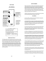
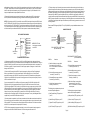
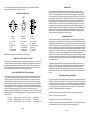
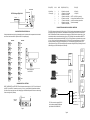
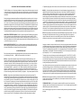
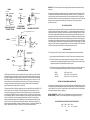
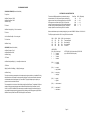
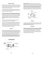
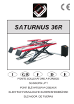
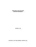
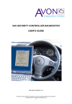
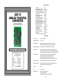
TABLE OF CONTENTS
ADC-16
ANALOG TO DIGITAL
CONVERTER
TECHNICAL REFERENCE
Specifications....................................... page 1
Connection Diagram and Warranty......... page 2
Power Supply Requirements................. page 3, 7 & 8
Set-Up, Testing & Trouble-Shooting..... page 3 & 4
RCT-8, RCT-16 Connection Diagram.... page 4
Connector Pin-Outs.............................. page 5 & 6
Direct Connection to a Modem............. page 6
Temperature Input................................ page 6
Input & Relay Expansion Ports.............. page 7
Power Supply Voltage Regulation......... page 7 & 8
Baud Rate & Protocol Selection............ page 8 & 9
RS-422, RS-423 & RS-485 Interfacing.. page 9
Input Amplification and Conditioning..... page 10
Differential Input & Optocouplers.......... page 10
Voltage Reference Inputs..................... page 10 & 11
Analog Inputs and Interfacing............... page 11, 12 & 13
10 Bit Analog Inputs............................. page 13
Control Software................................... page 13
Programming Examples......................... page 14 &15
Commercial Use of the ADC-16............. page 16
Rack Mounting....................................... page 16 & 17
Technical Support and Repair Service... page 17
SPECIFICATIONS
Power Supply.......................
9 to 14 volts DC (300MA)
Operating Temp. Range......
-40° C to +85° C
Serial Data Protocol.............
50 to 19,200 baud (defaults to 8 data bits, no parity & 1 or 2 stop bits)
Full duplex operation (compatible with all Windows operating systems)
Maximum Sampling Rate...... 1,700 samples per second (single channel, 8 bit at 19,200 baud)
Click for more info:
www.eeci.com/adc-16p.htm
ELECTRONIC ENERGY CONTROL, INC.
14960 Maple Ridge Rd
Milford Center OH 43045-9016
USA
PHONE*................. (937) 349-6000
FAX*...................... (614) 464-9656
ORDERS................ (800) 842-7714
TECH SUPPORT... (937) 349-6000
E-mail*.................... [email protected]
Web*........................http://www.eeci.com
*International & Domestic
Analog Inputs.......................
16 single-ended inputs (standard 8 bit resolution or optional 10 bit resolution)
(8 bit resolution will divide your measurement range into 256 different increments)
(10 bit resolution will divide your measurement range into 1,024 different increments)
Expansion Capability............ up to 112 relays (with up to (3) EX-32 or up to (7) EX-16 expansion cards)
up to 128 status inputs (with up to (4) ST-32 expansion cards)
up to 48 analog inputs (with AD-16 or AD-32 expansion cards)
up to 48 temperature inputs (with AD-16/AD-32 and temperature input options)
Software Compatibility.........
All Windows operating systems, DOS and most other operating systems.
Hardware Compatibility.......
Typically this will be all computers that support serial communications, from
the slowest 8086 to the fastest Quad core and newer.
Weight.................................
5 ounces
Size......................................
7 inches by 5 inches
Options Available.................
10 Bit Resolution, Temperature Input
TransZorb and Resetting Fuse
RS-485, RS-422 & RS-423 Serial Interface Standards
Page 1
POWER SUPPLY REQUIREMENTS
CONNECTION DIAGRAM
The ADC-16 may be powered from any DC voltage source which will supply 200 ma within a voltage range of 9 to 14
volts. The recommend power supply for use with a single ADC-16 card is the PS-GP-1 (wall transformer supply).
IMPORTANT: Use caution when connecting the power source, reversed polarity may cause damage. The heat
dissipation of the 7805 regulator on the ADC-16 will be greatly reduced with a 9 volt power source. The PS-9VDC-500
or PS-9VDC-1000 wall transformer power supplies may be used to power both the ADC-16 and expansion card(s)
without the need for additional regulators. Please note that the PS-12VDC-500 and PS-12VDC-1000 are unregulated
supplies and may produce voltages as high as 18 volts (see pages 7 & 8).
A D C - 1 6 A N A L O G TO
DIGITAL CONVERTER
J1
RED
ANALOG INPUT PORT #1
to connect inputs 1 thru 8
J2
J4
ANALOG INPUT PORT #2
to connect inputs 9 thru 16
INPUT EXPANSION PORT
connect up to (4) ST-32
status expansion cards for
an additional (128) status
inputs or (1) AD-16 or
AD-32 analog expansion
card for (16) or (32)
additional analog inputs
RED
J3
RED
RELAY EXPANSION PORT
connect up to (7) EX-16
expansion cards to control
up to 112 relays
SET-UP AND TESTING
Upon receiving your ADC-16, you should connect and test the operation of the hardware to verify proper operation.
Please set-up and test the ADC-16 as follows (Windows computers):
RED
ALL RIBBON CABLES MUST
BE INSTALLED WITH THE
NOTCH POINTING UP
(red conductor should be
positioned as shown)
TRS--+
ADC-16 TERMINAL BLOCK CONNECTIONS
(T)
(R)
(S)
(-)
(-)
(+)
POWER SUPPLY FUSING: A 500 milliamp (.5 amp) in-line fuse should be installed in series with the (+) power supply
lead to protect the power supply and the ADC-16 from damage (or order with the /T option).
RS-232 Transmitter ( connect to green wire)
RS-232 Receiver (connect to white wire)
(+) 12 volt control signal for use with RS-232 (connect to black wire)
RS-232 signal ground (connect to red wire)
Power supply (black wire)
(use caution, reversed polarity may
Power supply (red wire)
cause damage, 9 to 14 volts DC only)
WARRANTY AND CARE OF THE ADC-16
The ADC-16 Analog to Digital Converter is warranted against factory defects for a period of 90 days from the date of
purchase. The ADC-16 has proven to be extremely reliable in actual operation during field tests. We recommend that
the ADC-16 and associated hardware be installed in a suitable enclosure (4 mounting holes are provided on the
circuit board) and that reasonable precautions be taken to protect the circuit from static discharge. The most likely
damage to occur is that caused by lightning discharge through the power supply or serial I/O lines. The best way to
prevent this type of damage is to install a Power Protector (Part # SP-120 or Surgebuster #120K15A) in the electrical
outlet which supplies power to the hardware. Shielding the analog input lines will provide additional protection. If
further protection is desired, install a TransZorb across the power input to the interface card (part #SP-12K) and to
the RS-232 lines (part #SP-232K).
(1) Plug the serial cable into COM 1 of your computer and connect the other end to the terminal block on the ADC-16
(as shown on page 2). If you did not order a serial cable, a cable may be fabricated by soldering the wires to the proper
connector as shown on the following pages. Care should be taken to prevent any static discharge on the ADC-16 by
touching a metal ground before handling the ADC-16 and associated circuits. Use caution not to set the ADC-16 or
associated hardware on a metal surface or damage could result.
(2) Connect the power supply (part # PS-GP-1) to the six position terminal block at the bottom of the ADC-16. Be sure
to observe the (+) and (-) connections on the ADC-16 (reversed polarity may cause damage). Connect the RTC-16
terminal block to ports #1 and #2 on the ADC-16. The ribbon cables for the RTC-16 should be routed underneath the
ADC-16 so that the RCT-16 is on the right side of the ADC-16.
(3) The ADC-16 is set to 9,600 baud at the factory. This is the proper setting for use with the test software which is
provided on CD with your order. NOTE: If any of the analog ports have been configured for temperature input, skip
this section and complete the set-up and testing requirements which are described in the TE-8 technical reference.
If your operating systems is Windows 95, 98, ME, or Windows 2000 you must use the Universal App on the installation
CD for testing your ADC-16. Windows XP, Vista, Windows 7, Windows 8 and up users may install the .Net App* which
uses the Microsoft .Net Framework. Click the install App button on the installation CD startup window or run setup.exe
in the folder Windows Data Acquisition Program. If prompted about an older file, keep your newer file. Once installed,
run the ADC-16 program. The program defaults to Com 1. Other Com ports may be selected if required.
*Please note that the Microsoft .Net Framework must be installed on your system. If the .Net Framework is not installed
on your computer, the ADC-16 installation program will attempt to download and install the .Net Framework from the
Microsoft web site through your internet connection. This may take 5 minutes or longer. In order for the .Net
Framework to install correctly, your computer must be up to date with Windows update (Windows XP must have
service pack 3 installed). This is especially important with Windows XP and Vista. You may update your computer by
clicking on the start button, All Programs, Windows Update and clicking on "Check for Updates".
Your screen should show a row of eight or sixteen numbers. The top 8 numbers represent the analog inputs for port #1
and the bottom 8 numbers represent the analog inputs for port #2. The numbers may be fluctuating as a result of noise
on the analog inputs (this is normal).
(4) Test each analog input by connecting each input (one at a time) to the reference (-) terminal on the RCT-8 or RCT16 (see page 4). Your screen should show a "0" for that input. After this is completed, connect each input (one at a
time) to the reference (+). Your screen should show a "255" for 8 bit inputs or "1023" for 10 bit inputs for each input. If
Page 2
Page 3
additional testing is desired, connect a 10k ohm 20 turn potentiometer to each input (one at a time) as shown on page
12, figure B. The input shown on the screen should increment from 0 to 255 (8 bit) or 0 to 1023 (10 bit). The number
shown for each input should increment by one (in 256 increments for 8 bit inputs) or (in 1024 increments for 10 bit
inputs) as the potentiometer is slowly adjusted from 0 to 20 turns.
(5) If operation of the analog inputs are normal, then testing is now complete and your ADC-16 may be placed in
service. If problems are encountered during testing, proceed to the trouble-shooting procedures shown below.
NOTE: The (S) terminal on the ADC-16 is provided for use as an RS-232 control signal for use with the RS-232 control
lines CTS, DSR and DCD. If the ADC-16 does not function with custom software, connect the (S) terminal (black wire)
to all three control lines (CTS, DSR and DCD). The pins for these control lines on a DB-9 connector are pins 8, 6 and 1.
The (S) terminal may also be used to supply a signal to one of the RS-232 control lines for use as a supervisory signal
to sound an alarm with your software when the ADC-16 has lost power or has been disconnected (see utilities).
(4) The input voltage to any of the analog inputs must not exceed the reference voltage (nor should the input go
negative with respect to the reference) or erratic data may be generated on one or more of the analog channels.
When an external reference is used, the reference voltage must be within 100 millivolts of the supply voltage to the
ADC0809 IC (approximately 5 volts DC) when operating in a MODE (2) jumper configuration (see pages 10 & 11).
When operating in a MODE (3) jumper configuration (8 bit only), the reference voltage must be a minimum of 1.2
volts and the reference voltage must be centered about the supply voltage to the ADC0809 IC. When operating in a
MODE (3) jumper configuration, the input voltage to any of the analog inputs must not exceed the reference voltage
(nor should the input go negative with respect to the reference) or erratic data may be generated on one or more of
the analog channels.
Please contact EECI Support at (800) 842-7714 or (937) 349-6000 if you require additional assistance or have
questions.
CONNECTOR PIN-OUTS
RCT-8 CONNECTION DIAGRAM
Red Line
RCT-8
Ribbon Cable to
ADC-16
Analog Input #1
Analog Input #2
Analog Input #3
Analog Input #4
Analog Input #5
Analog Input #6
Analog Input #7
Analog Input #8
(+ Reference)
(- Reference)
(6) Data Set Ready
(7) Request to Send
(8) Clear to Send
NOTE: The RCT-16 will
have the same connections
as two RCT-8
(1) Data Carrier Detect
(2) Received Data
(3) Transmitted Data
(4) Data Terminal Ready
(5) Signal Ground
(20) Data Terminal Ready
DB-9 CONNECTOR...SOCKET (female)
(rear view/solder side)
DB-25 CONNECTOR...SOCKET (female)
(rear view/solder side)
TROUBLE-SHOOTING THE ADC-16
(1) Verify power to the ADC-16 by checking for 5 volts DC on the 2200 mf capacitor (low voltage may indicate an
overload). Verify that the ADC-16 is set to the same baud rate as what appears on the test software screen. Check for a
minimum of 9 volts DC at the ADC-16 power input (on the 6 position terminal block) and check for correct polarity. The
RS-232 driver on the ADC-16 requires a minimum of 9 volts for proper operation. A voltage over 14 volts will cause
damage to the RS-232 driver.
(2) Check the Com Port used with the ADC-16. Open device manager by clicking on the "Open Device Manager"
button on your installation CD (or by going to control panel). Click the small triangle (or +) to the left of Ports to
expand the Ports category, right click on the Com port that you have the ADC-16 connected to and click properties.
Check the Com port status and verify that you have the test program set to this Com port and verify that you have the
ADC-16 connected to this Com port.
If you are connecting the ADC-16 to a USB port, the Com port entry must be "Prolific USB to Serial Comm Port".
Right click on this entry, click properties and open the Driver tab. Your USB Com driver must be Prolific version
3.4.62.293 or higher (dated 10/17/2013 or later). If your USB Com driver is not up to date, then right click the "Prolific
USB to Serial Comm Port" entry and click update driver. If you do not see a "Prolific USB to Serial Comm Port" entry
then the USB cable driver is not correctly installed. You may re-install the driver from the supplied CD or Windows
Update. You may verify that you have the ADC-16 connected to this "Prolific USB to Serial Comm Port" entry by
watching the entry and unplugging the ADC-16 USB cable from your computer. The entry should disappear and then
re-appear when you re-connect the USB cable to the ADC-16.
(3) If erratic operation is experienced, check for loose connections at the ribbon cable connections and terminal block
(tug on each wire going into the terminal block), check for power supply interruptions or short circuits caused by metal
contact to the ADC-16 circuit areas or other connected hardware. When more than three EX-16 cards are connected
to the ADC-16, an external power feed is required (see EX-16 manual).
NOTE 3: With some programming languages the semicolon (;) at the end of the command is used to suppress the
carriage return and line feed. A line feed will transmit a "10" and a carriage return will transmit a "13".
Page 4
(1) Equipment Ground
(2) Transmitted Data
(3) Received Data
(4) Request to Send
(5) Clear to Send
(6) Data Set Ready
(7) Signal Ground
(8) Data Carrier Detect
DB-9 Pins
Connection
DB-25 Pins
(1) Data Carrier Detect* (connect to black
wire or terminal (S) on the ADC-16)
NOTE: This connection is not needed on
most computers.
(2) Received Data (connect to green wire
or terminal (T) on the ADC-16)
(3) Transmitted Data (connect to white wire
or terminal (R) on the ADC-16)
(5) Signal Ground (connect to red wire or
terminal (-) on the ADC-16)
The following pins are optional and may be used
as needed for specific applications.
Connection
(2) Transmitted Data (connect to white wire
or terminal (R) on the ADC-16)
(3) Received Data (connect to green wire
or terminal (T) on the ADC-16)
(7) Signal Ground (connect to red wire or
terminal (-) on the ADC-16)
(8) Data Carrier Detect* (connect to black
wire or terminal (S) on the ADC-16)
NOTE: This connection is not needed on
most computers.
The following pins are optional and may be
used as needed for specific applications.
(4) Data Terminal Ready (DTR) output from
your PC.
(4) Request to Send (RTS) output from your PC.
(6) Data Set Ready (DSR) input to your PC.
(5) Clear to Send (CTS) input to your PC.
(7) Request To Send (RTS) output from your PC.
(6) Data Set Ready (DSR) input to your PC.
(8) Clear To Send (CTS) input to your PC.
(20) Data Terminal Ready (DTR) output from your PC.
Page 5
EXPANSION PORTS
* On some types of computers, the Data Carrier Detect must be held high (+12 volts) before the RS-232 port is
enabled. The (S) terminal on the ADC-16 will provide the +12 volts.
ADDITIONAL CONNECTOR PIN-OUTS
ARROW
(4)
(1)
(5)
(3)
(2)
(4)
(3)
(5)
(2)
5 PIN DIN
(Apple)
Pin # Connection
(1) DTR
(2) Signal Ground
(3) DSR
(4) Transmitted Data
(5) Received Data
(1)
(2)
(3)
(4)
(5)
(6)
(7)
(8)
(9)
(1)
8 PIN MINI-DIN
(Mac & IBM)
RS-485
(DB-9 plug)
Pin # Connection
(1) DTR
(2) DSR, DCD & CTS
(3) Transmitted Data
(4) Signal Ground
(5) Received Data
Pin # Connection
(2) Transmitter (+)
(3) Equipment Ground
(4) Receiver (+)
(7) Transmitter (-)
(8) Receiver (-)
NOTE: The above connector illustrations are viewed from the rear (solder side).
CONNECTION OF THE ADC-16 DIRECTLY TO A MODEM
The ADC-16 may be connected directly to a modem at a remote location without the need for a PC at the remote site.
The modem at the remote site is then considered DCE equipment (Data Communications Equipment) and requires
that the serial transmitter and receiver lines be reversed (pins 2 & 3 on a DB-25 and DB-9) when connecting to the
ADC-16. When the ADC-16 is connected directly to a computer, the computer is considered to be DTE equipment
(Data Terminal Equipment) and the pin-outs shown on the preceding page are correct.
OPTIONAL TEMPERATURE INPUTS FOR THE ADC-16 AND ADC-8
The ADC-16 may be configured for temperature input by specifying the E and/or F options when ordering the ADC16. The inputs are converted to temperature in groups of eight. The ADC-16 may be ordered with 8 temperature
inputs and 8 analog inputs or with all 16 channels converted for temperature input. The 8 bit inputs require that a
voltage reference and several additional components be installed on the ADC-16 card. Once the 8 bit inputs have
been converted for temperature input, the analog input port (all 8 channels) will be dedicated for use as temperature
input only. When the ADC-16 or ADC-4 is equipped with 10 or 12 bit inputs, additional components are not required
for temperature input. The 10 bit inputs are converted to temperature input by connecting the TE-8 temperature input
card to the 10 bit analog input port (removal of the TE-8 from the ADC-16 allows the inputs to be used for
conventional analog input). The temperature error of the TE-8 is typically less than 1 degree F. Greater accuracy may
be obtained with the use of the extended range temperature sensors. The temperature input ranges for 8 and 10 bit
inputs are as follows:
The ADC-16 provides two expansion ports for additional I/O operations using a single COM port. The Relay
Expansion Port allows up to (112) relays (or other output devices) to be controlled by software or keyboard input
(using EX-16 or EX-32 relay expansion cards). Each EX-16 expansion card will provide control for 16 additional
relays. A total of seven EX-16 expansion cards may be connected to the AR-16, ADC-4(8)(16) or STA-8(16). The first
EX-16 expansion card is connected to the relay expansion port on the AR-16, ADC-16 or STA-16 using the RC-20
ribbon cable. Additional EX-16 expansion cards connect to the preceding EX-16 with the RC-20 ribbon cable. The
relay output ports on the EX-16 are identical to those on the AR-16 and accept the same relay cards and other
accessories as the AR-16. Shunts on the EX-16 are used to select the relay output port desired. A variety of relay
cards with various contact configurations are available for connection to the EX-16 expansion cards. Relays are
controlled by transmitting a relay code (32 thru 255). Each relay is assigned 2 codes, one to energize the relay and
the other to de-energize the relay. The relay code is determined by using the following formula: RELAY CODE =
(RELAY # times 2) - 1...to energize the relay or RELAY CODE = (RELAY # times 2) - 2...to de-energize the relay.
Additional information is provided with the EX-16 relay expansion card.
ADDING ADDITIONAL INPUTS
The Input Expansion Port allows up to (128) additional status inputs or (32) additional analog inputs to be read by
software (using up to (4) ST-32 status expansion cards or (1) AD-16 or AD-32 analog expansion card). Each ST-32
expansion card will provide an additional 32 status inputs. The first ST-32 card connects to the input expansion port
on the ADC-16. Additional ST-32 cards connect to the preceding ST-32 card. One AD-16 or AD-32 analog expansion
card can be connected to the ADC-16 in place of the ST-32 expansion cards to provide an additional 16 or 32 analog
inputs. If more than 48 analog inputs are required, contact technical support for customized hardware. The software
channel codes for the AD-16 analog inputs are 16 to 31. The additional analog inputs are identical to those described
on pages 9, 10 & 11 for the ADC-16 and the software is handled in the same manner with the exception of the
channel codes. The status inputs are read by transmitting a single byte status port code to the ADC-16. Transmitting
a 16 would request information for the first 8 status inputs on the ST-32 status expansion card. The ADC-16 would
then transmit a single byte number (each bit representing one status input). Additional information is provided with the
ST-32 status expansion card.
For applications requiring more than 32 analog inputs/128 status inputs or applications requiring more than 112
relays, the PS-4 or PS-8 port selector may be used as a bank selector to select one bank of 32 analog inputs/128
status inputs and 112 relays. In this manner, up to 4,096 analog inputs or up to 16,384 status inputs may be
connected and 14,336 relays may be controlled (128 banks times 112 relays and 128 status inputs or 32 analog
inputs). An example of this method is shown on page 9 using four banks to provide 128 analog inputs and control of
448 relays.
USE OF UNREGULATED WALL TRANSFORMERS
The PS-12VDC-1000 and PS-12VDC-500 power supplies are unregulated and may produce voltages substantially
higher then the 12 volts DC that is labeled on the device. The 7805 regulator on the ADC-16 and any relays powered
by the higher voltage may produce an excessive (and undesirable) amount of heat which may require additional air
flow or ventilation to prevent overheating. Voltages over 14 volts DC may damage the Maxim IC on the ADC-16. The
7812 regulator (supplied with the power supply) may be used to regulate voltage to the ADC-16 and relay card(s).
Connect the 7812 regulator as shown below and on the following page:
BLACK WIRE: connect to the (-) terminal on the ADC-16 and to the (-) wire coming from the power supply.
RED WIRE:
(8 bit inputs)
(10 bit inputs)
(10 bit inputs)
temperature range -40° F to 146° F (-40° C to 64° C)
temperature range -40° F to 212° F (-40° C ro 100° C)
temperature range -67° F to 302° F (-55° C to 150° C)
standard sensors
standard sensors
extended range sensors
connect to the (+) terminal on the ADC-16.
YELLOW WIRE: connect to the (+) wire coming from the power supply.
USE CAUTION: The metal tab on the regulator is electrically connected to the (-) wire (black). Before connecting the
red & black wires to the ADC-16, check for 12 volts DC across the wires (red should equal (+)).
Page 6
Page 7
YELLOW WIRE
12V REGULATOR
ADC-16 Analog to Digital Card
7812
(-)
RED WIRE
(+)
POWER
SUPPLY
T R S - - +
WIRE
NUT
BLACK WIRE
BAUD RATE SELECTION FOR THE ADC-16
Select the desired baud rate by placing the removable shunts in the positions which correspond to the desired baud
rate. All four of the shunts must be in place for the ADC-16 to operate properly.
BAUD RATE
BAUD RATE
50
1800
75
2000
110
PIN 39 (EPE)
WLS1
WLS2
SBS (PINS 38, 37, 36)
PIN 35 (PI)
0 = Odd Parity
1 = Even parity
0
0
1
1
0
0
1
1
0
0
0
0
1
1
1
1
0
1
0
1
0
1
0
1
0 = Parity On
1 = Parity Off
(5 data bits, 1 stop bit)
(5 data bits, 1.5 stop bits)
(6 data bits, 1 stop bit)
(6 data bits, 2 stop bits)
(7 data bits, 1 stop bit)
(7 data bits, 2 stop bits)
(8 data bits, 1 stop bit)
(8 data bits, 2 stop bits)
NOTE: 1=(+5 VDC), 0=(ground (-))
All pins must be connected to 5 volts or
ground. Do not allow any pins to float
(pins left unconnected).
RS-485 INTERFACING AND RS-232 DISTANCE LIMITATIONS
The RS-232 interface will allow the AR-16, ADC-4(8)(16) or STA-8(16) interface cards to be located up to 50 feet from
the computer using a single 3 conductor wire. When distances need to be greater, the RS-422, RS-423 and the RS422A, RS-485 interfaces will allow the Interface card to be located up to 4,000 feet from the computer using a 2 pair
communications cable (4 conductor/2 twisted pairs of wire or CAT5). Shielding of the communication cable/CAT5 is
recommended to protect against electrical storm EMI. The PS-4 or PS-8 port selector may be used to select one port
(1 of 4 or 1 of 8) to control up to 8 interface cards (ADC-16, STA-16 or AR-16) at various locations up to 4,000 feet
from the port selector, providing up to 256 analog inputs, up to 1,152 status inputs and providing control of up to
1,024 relays. A total of up to (16) PS-8 port selectors may be connected to a single RS-232 port, allowing for a total of
4,096 analog inputs, 18,432 status inputs and 16,384 relays.
AR-16, ADC-4
ADC-8, ADC-16,
STA-8 or STA-16
2400
134.5
3600
150
4800
AR-16, ADC-4
ADC-8, ADC-16,
STA-8 or STA-16
RS-232
Interface
50 feet
RS-485 option
AR-16, ADC-4
ADC-8, ADC-16,
STA-8 or STA-16
300
7200
EXAMPLE SHOWS 9,600
BAUD SELECTED
600
9600
1200
19200
AR-16, ADC-4
ADC-8, ADC-16,
STA-8 or STA-16
RS-485
Interface
4,000 feet
RS-485 option
AR-16, ADC-4
ADC-8, ADC-16,
STA-8 or STA-16
CHANGING PROTOCOL SETTINGS
PARITY, WORD LENGTH and STOP BITS: These functions are selected using pins 35, 36, 37, 38 and 39 on the 40
pin UART IC on the ADC-16. Connect the pins to the (+) 5 volt or (-) ground power feed (located above and below
pins 35 thru 39) as shown in the chart on the following page to select the desired protocol. Be sure to cut the existing
circuit track using a knife (if different).
RS-232
Interface
4,000 feet*
50 feet
PS-4 PORT
SELECTOR
(-)
40 PIN UART
4,000 feet*
35
36
37
38
39
Bottom View
(solder side)
40
4,000 feet*
(+)
RS-485 option
AR-16, ADC-4
ADC-8, ADC-16,
STA-8 or STA-16
4,000 feet*
The PS-4 converts the computer RS-232
into (4) software selectable RS-485 ports
(also available in RS-422A/RS-422).
* Two twisted wire pairs
RS-485 option
Page 8
Page 9
VOLTAGE INPUT AMPLIFICATION AND SIGNAL CONDITIONING
317 adjustable voltage regulator, 500 ohm trimmer, 240 ohm and 390 ohm resistors on the top right side of the ADC-16.
The ADC-16 defaults to a 0 to 5 volt input range (installation of a voltage reference will allow input ranges as low as 0 to
1.2 volts when using 8 bit inputs). When the input voltage range is required to be lower, (such as with a watt transducer
or load cell) an external instrumentation amplifier must be used to amplify the input signal to the 0 to 5 volt input range
of the ADC-16.
MODE (3).....(8 bit only) Adjusted voltage reference input. In this mode of operation the voltage input level may be
adjusted to allow input of lower analog voltages (down to about 1.2 volts full scale). The MODE (3) configuration is
selected by removing the voltage reference jumpers (J1 and J2 for port #1 or J3 and J4 for port #2) and installing a
limiting resistor (3K typical) in place of both jumpers. It is important that both resistors be installed because the
reference voltage must be centered about the supply voltage of the 0809 chip. Conversion errors may occur (due to the
design of the 0809 chip) if the center of the reference voltage is not equal to the center of the supply voltage (plus or
minus .1 volt). The voltage reference device is then connected to the voltage reference input (terminal #9 (+) and #10 () on the RCT-8). The voltage reference may be soldered directly to pins #12 (+) and #16 (-) on the 0809 chip for greater
stability. The voltage reference device may be a simple zener diode or LED for less critical applications (use (2) 180
ohm resisters in place of jumpers for LED). When the voltage reference is 2.5 volts or less, the installation of a 470 mf
capacitor on the ADC-16 is recommended (holes are provided near the center of the card above J3 with the positive
lead marked). The use of a temperature compensated voltage reference will result in greater accuracy and less drift.
You may contact our technical support staff for more information on the voltage references which we stock.
Several general purpose instrumentation amplifiers are available to amplify lower signal levels to the 0 to 5 volt range
required by the ADC-16 (for use with 8, 10 and 12 bit inputs). The VA-1 is a single channel amplifier for connection to
the ADC-4, ADC-8 or ADC-16. The VA-2, VA-4 and VA-8 amplifiers are two, four and eight channel versions of the
VA-1. The VA-1, VA-2, VA-4 and VA-8 all provide 15 turn potentiometer(s) for gain adjustment (amplification level). The
amplification level is adjusted for a 0 to 100 millivolt input at the factory. The amplification level may adjusted for signal
inputs as low as 0 to 5 millivolts or as high as 0 to 5 volts. Lower signal levels (such as the output signal from a watt
transducer, pressure transducer, load cell, etc.) with typical full scale voltages of only 20 to 100 millivolts will require the
addition of the VA-1 instrumentation amplifier. Signal levels this low will require shielded wire in place of a twisted pair.
The shield should be left disconnected at the source and grounded to an earth electrical ground at the VA-1.
CONNECTION OF DIFFERENTIAL SIGNALS: The ADC-16 inputs are single-ended. If differential inputs are required,
the VA-1 may be used to convert a differential signal into a 0 to 5 volt signal for connection to the ADC-16. The VA
series amplifiers have a reference input (for connection to the ADC-16 reference) which is used to generate a 2.5 volt
offset. The gain adjustment on the VA series amplifiers may be adjusted to allow for differential signals as low as (+) and
(-) 5 millivolts or as high as (+) and (-) 5 volts.
ANALOG LINEAR OPTOCOUPLERS: The VI-1I or VI-8I linear optocoupler instrumentation amplifiers may be used
when the analog input signal must be electrically isolated (such as with some types of pressure transducers, signals
with ground referenced offsets or for signals which must be isolated for safety).
VOLTAGE REFERENCE INPUT
Each 8 channel analog input port has a separate voltage reference input and each port may be selected to function in
any of the following three modes.
NOTE: 10 bit inputs are limited to a 5 volt reference.
MODE (1).....Voltage reference equals power supply. With the factory jumpers installed, the reference (+) and
reference (-) will be equal to the power supply voltage (5 volts and ground, plus or minus .25 volts). The voltage input
scale will be 0 to 5 volts (20 millivolt resolution with 256 increments for 8 bit inputs or 5 millivolt resolution with 1,024
increments for 10 bit inputs). The ADC-16 will then transmit (255)* with a 5 volt input, (0) for a 0 volt input, (128) for a
2.5 volt input and other values corresponding to the following formula: voltage times (51) = X, where X = the integer
value transmitted. EXAMPLE: 1.9 volts times 51 = 96.9. The ADC-16 would then transmit (97) decimal (in binary) to
represent a 1.9 volt analog input. The use of the power supply for the voltage reference will be adequate for most
applications. MODE (1) is selected when both jumpers are installed (J1 and J2 for port #1, or J3 and J4 for port #2), all
8 channels of the analog port will then function in the MODE (1) configuration. *binary number represented in decimal
MODE (2).....Voltage reference equals calibrated external voltage reference equal to power supply voltage. This
method will provide a greater degree of accuracy for analog inputs which need to be referenced to the actual volt (use
of the power supply for actual volt reference may introduce small errors due to variations in the power supply caused by
activity of the ADC-16 functions). To select the MODE (2) configuration cut the (+) reference voltage jumper (J1 for port
#1 or J3 for port #2). The jumpers to the (-) reference voltage should be left in place (J2 for port #1 or J4 for port #2). A
calibrated voltage equal to the ADC-16 power supply (plus or minus .1 volt) should be applied to the voltage reference
input (terminal #9 (+) and #10 (-) on the RCT-8). The voltage input may be any well regulated power supply which can
be adjusted to the desired voltage without drift (for greater stability a temperature compensated power supply may be
used). To determine the proper voltage, measure the ADC-16 power supply voltage on the 28 pin 0809 chip (pins #11
and #13). The resolution will be equal to the reference voltage input divided by 256. All 8 channels of the analog input
port will then function in the MODE (2) configuration with J1 (port #1) or J3 (port #2) cut and the external voltage
reference connected. The ADC-16 has the capability of providing an on-board voltage reference by installing a
Page 10
NOTE: The analog voltage input must not be higher than the ADC0809 power supply voltage for modes 1 and 2 or the
rated voltage of the voltage reference device for mode 3. In all cases the input voltage must not go negative (or
negative with respect to the reference in the case of MODE (3) operation). Failure to observe these voltage input
restrictions may result in erratic or incorrect conversion results on one or more of the analog channels.
ANALOG VOLTAGE INPUTS
Voltages up to hundreds of volts may be divided down to the 5 volt range by using a simple resistance divider as shown
on the following page (the signal source must be capable of driving a 1 ma load). To determine the value transmitted by
the ADC-16 for a specific voltage applied to the divider circuit use the following formula: (VI divided by DF) times 51 =
TV (where TV = transmitted value sent by the ADC-16, VI = voltage input to divider, DF = divider factor) DF = full scale
voltage divided by 5 volts. EXAMPLE: 100 volts full scale divided by 5 = 20 = DF. A 60 volt input to the divider divided
by 20 multiplied by 51 = 153 = TV, the value transmitted by the ADC-16.
The voltage input source may be located up to several hundred feet from the ADC-16. The RCT-8, RCT-16 or RCP-8
are used to make the wire connections. The wire which connects the RCT-8 to the signal source should be a twisted
pair to reduce possible input noise (22 or 24 gauge communication cable or CAT5typical). Shielded cable may be used
to further protect against EMI or lightning noise (the shield should be left disconnected at the source and connected to
an earth ground/equipment ground at the ADC-16).
Lower millivolt signal levels (such as the output signals from a watt transducer, pressure transducer, load cell, etc.) with
typical full scale voltages of only 20 to 100 millivolts will require the addition of the VA-1, VA-2, VA-4 or VA-8
instrumentation amplifier. The VA-1 connects to any of the analog inputs and will convert a millivolt signal input to a 0 to
5 volt output for input into the ADC-16. Signal levels this low will require shielded wire in place of the twisted pair. An
adjustment on the VA-1 will set the input scale. The shield should be left disconnected at the source and grounded to
an earth ground at the VA-1. Applications requiring isolated analog inputs require the VI-8I linear optocoupler amplifier.
NOTE: When the analog inputs are left floating, (no connection) the ADC-16 will transmit fluctuating numbers as a
result of noise present at the inputs. We recommend that any unused inputs be connected to reference (-) to prevent
possible errors on other channels.
FILTERING INPUT NOISE: A .01 mf filter capacitor is installed on the ADC-16 card (one for each channel) which
significantly reduces errors and fluctuation as a result of input noise. A 2.7 mf or 10 mf tantalum capacitor may added for
additional filtering (input response time will be slower).
Shown on the following page in figures A, B & C are methods for reading contact closure, potentiometer movement &
light levels.
Page 11
FIGURE B
Switch or Relay
Contacts etc.
DIGITAL INPUT
(Reference +)
(0=OFF)
(255=ON)
10 mf Tantalum Capacitor
27K Ohm
To Analog
Input
10K OHM
TYPICAL
(+)
10 K ohm
IMPORTANT: The full scale voltage used should be the highest possible voltage that could be present at the high
voltage input.
FIGURE C
+
FIGURE A
Ref (-)
To Analog Input
Ref (+)
To Analog Input
(Reference -)
(Reference +)
(Reference -)
POTENTIOMETER
MOVEMENT SENSING
USING AN ANALOG INPUT
FOR ON/OFF STATUS
Cadmium Sulfide
Photo Cell
8 BIT CONTROL SOFTWARE
MEASURING LIGHT LEVELS
Fuse or Limiting Resistor (330 ohm 1 watt)
1 Amp Diode (50 volt)
AC Primary Voltage
120, 277, 480 etc.
6 or 12 Volt
Secondary
R1
(+)
FIGURE D
AC voltages may be applied to the high voltage input if a diode is connected in series and a filter capacitor (100 mf,
35 volt typical) is connected between the ADC-16 analog input and the ADC-16 reference (-). AC voltages over 24
volts or great enough to create an electrical shock hazard or fire should be connected to the ADC-16 analog input
using a step-down transformer to reduce the high voltage down to the 5 volt range as shown in figure D. A diode and
filter capacitor must be connected on the secondary side of the transformer (a common low current power
transformer may be used).
100 mf
35 volt
R2
To Analog
Input
(-)
24 ga Communication Cable
Analog information is transmitted from the ADC-16 upon receipt of a channel code which must be transmitted by the
computer. The channel code is equal to the channel number - 1. To acquire the analog information on channel 1 the
computer must first transmit a (0). Because of the delay which is required for the 0809 chip on the ADC-16 to make
the conversion, the analog data transmitted will be for the previous channel requested. If information from just one
analog input is desired, it will be necessary for the channel code to be transmitted twice. The data transmitted by the
ADC-16 after the first transmission will be invalid. The following transmission by the ADC-16 will be the analog data
on that channel at the time that the first channel code was received. The data byte transmitted by the ADC-16 will be
a binary number equal to 0 to 255 decimal (0 = 0 voltage at the analog input, 255 = full scale voltage, 128 = half scale
voltage, etc.). The ADC-16 will only recognize channel codes 0 to 15 (or 0 to 31 with the AD-16 or ST-32 connected).
The ADC-16 passes all higher codes to the EX-16 (if connected) for relay control functions.
10 BIT ANALOG INPUTS
Diode
R1
The 10 bit option of the ADC-16 functions very similar to its 8 bit counterpart with the exception of the following:
(1) Input voltage range should be maintained at 0 to 5 volts DC (5.0 volts across the voltage reference inputs).
1/4 Amp Fuse
10 Volt 5 Watt
Zener Diode
+
R2
To Analog
Input
(-)
(+)
High Voltage
AC/D C Input
(+)
FIGURE E
(1 ma maximum current
through resistors)
(-)
100 mf
35 volt
Ground for
Safety
(2) The ADC-16 will transmit in two byte format as opposed to the single byte format of the 8 bit. The first byte
received will be the most significant digits (all eight bits are used). The second byte received will be the least
significant two digits (the first 6 bits will always be zero and are not used).
(3) The sampling rate of the 10 bit version will be less than half that of the 8 bit as a result of the two byte format
of the 10 bit converter (approximately 500 samples per second for a single channel at 19,200 baud).
HIGH VOLTAGE INTERFACING
CAUTION: When working with high voltages, the potential for fire, explosion, electrocution, eye injury or blindness
and life threatening injuries or death exists. If you are not familiar with the precautions needed when working with
high voltages, do not attempt to connect high voltage up to these circuits. To prevent the danger of a high voltage
feeding back to the ADC-16 and the fire/injury/electrocution hazard caused by an open or short circuit, a 10 volt 5
watt zener diode and 1/4 amp fuse should be connected as shown in figure E. Wire used to interconnect a high
voltage input must be rated for use with the higher voltage. When connecting the ADC-16 to high voltage AC
equipment the method shown in figure D above is recommended.
The following method is used to divide a high voltage down to the 5 volt range needed for input into the ADC-16. This
method involves the use of two resistors (R1 and R2) which together add up to Rt (total resistance). The total
resistance is determined by using the Ohms Law to compute the resistance needed for a 1 milliamp current flow
through the resistors. EXAMPLE: If your full scale voltage is 100 volts (R = E divided by I) 100 volts divided by .001
amp = 100,000 ohms (100K ohm). To determine the proper ratio, divide 5 volts by the full scale voltage. 5 divided by
100 volts = .05. Multiple this ratio by the total resistance to determine the value of R2. R1 is then equal to the
difference between the total resistance and R2. EXAMPLE: ratio .05 times total resistance 100,000 ohms = 5,000
ohms (the value of R2). Total resistance 100,000 ohms less R2 5,000 ohms = 95,000 ohms (the value of R1). To
determine the power rating needed for the resistor, use the following formula: P = I squared times R. EXAMPLE: .001
squared = .000001 times R1 95,000 ohms = .095 watts. A 1/8 or 1/4 watt resistor would be sufficient.
Page 12
ADC-8G
ADC-16G
ADC-16GH
(ADC-8 port #1 = 10 bit)
(ADC-16 port #1 = 10 bit, port #2 = 8 bit)
(ADC-16 port #1 = 10 bit, port #2 = 10 bit)
SYSTEMS LEVEL PROGRAMMING CONSIDERATIONS
In Basic and other high level programming languages, the Line Status Register is automatically checked for incoming
and outgoing bytes and handles the data flow as needed. When reading or writing to the COM port registers directly
(such as in Assembly, C or using the OUT command in Basic), it will be necessary to check the Line Status Register
before reading or writing the incoming or outgoing byte.
BEFORE TRANSMITTING.... check BIT 5 of the Line Status Register before sending byte (bit must be high)
BEFORE RECEIVING.... check BIT 0 of the Line Status Register before accepting byte (bit must be high)
I/O PORT REGISTER LOCATIONS FOR THE LINE STATUS REGISTER
COM 1
3FD
COM 2
2FD
COM 3
3ED
Page 13
COM 4
2ED (hex values)
PROGRAMMING EXAMPLES
VISUAL BASIC EXAMPLE (Microsoft Visual Studio)
SYSTEMS LEVEL BAUD RATE SELECTION
'To open Com:
The baud rate for IBM & compatibles may be selected by turning on
the baud rate latch (bit 7 of the line control register) and setting the
registers as shown to the right. Basic programmers may use the OPEN
COM command to set the baud rate for COM 1 & 2 in place of this
method. The baud rate and protocol for COM 3 & 4 should be selected
from Basic by using the above procedure and the OUT command. An
example is provided on the test disk using COM 3 & 4 from Basic.
SerialPort1.PortName = "COM1"
SerialPort1.BaudRate = "9600"
SerialPort1.Open()
'To Transmit:
SerialPort1.Write(chr(XOut))
'XOut is channel code
MSB LSB (decimal)
1
128
0
192
0
96
0
12
0
6
Other standard baud rates may be selected by adjusting the given values. EXAMPLE: 4800 baud = 1/2 of 9600 = 24
'To Receive:
XIn = SerialPort1.ReadByte
Baud Rate
300
600
1200
9600
19200
The COM port register locations for COM 1 through COM 4 are shown below.
'XIn is analog data
COM 1
3F8
3F8
3F9
3FB
'To Close Comm:
SerialPort1.Close()
C# EXAMPLE (Microsoft Visual Studio)
COM 2
2F8
2F8
2F9
2FB
COM 3
3E8
3E8
3E9
3EB
//To Transmit:
LINE CONTROL
(Bit 0) (Bit 1) Word Length
0
0
5 data bits
1
0
6 data bits
0
1
7 data bits
1
1
8 data bits
serialPort1.Write(channelByte,0,1); //channelByte is channel code
(Bit 2)
0 = 1 stop bit
1 = 2 stop bits
(Bit 3)
0 = no parity
1 = parity enabled
serialPort1.Close();
(Bit 4)
The entire source code program examples and the complete project code are provided on your installation CD along
with additional source code examples in other programming languages. The programs are intended to demonstrate
the fundamentals needed for development of your own software. The program examples may be copied to your
program and used as a subroutine if desired.
0 = even parity
1 = odd parity
(Bit 5)
0 = logical 1
1 = logical 0
(Bit 6)
1 = break command
(Bit 7)
0 = baud latch off
1 = baud latch on
serialPort1.PortName = "Com1";
serialPort1.BaudRate = 9600;
serialPort1.Open();
//To Receive:
InByte[i] = serialPort1.ReadByte();
//InByte[i] is analog array
These examples will run in all versions of Visual Studio including Visual Studio Express. The installation CD will have
examples in all the programming languages used with Microsoft Visual Studio including Visual Basic, Visual C#,
Visual C++ and ASP .Net. Additional source code examples are available in several other variations which may be
more suitable for alternate programming languages (including interfacing to older DOS programs using GW Basic or
QuickBasic if needed). Please contact EECI technical support for more information.
COM 4
2E8
2E8
2E9
2EB
(hex values shown)
Transmitter/Receiver
Baud Latch LSB
Baud Latch MSB
Line Control
NOTE: The ADC-16 will function with any RS-232 COM
port (or RS-422 & RS-485 with option).
Page 15
Page 14
COMMERCIAL USE OF THE ADC-16
When the ADC-16 is to be used in a commercial/industrial environment, additional action must be taken to insure long
term reliability and trouble free operation of the hardware. In general, the most serious threat to the hardware will be
electrical transients (most often caused by electrical storm activity). The following steps are strongly encouraged to
protect the hardware and are listed in the order of highest priority:
MOUNTING A STAND ALONE UNIT...A single interface card may be mounted in an enclosure or on a metal
mounting panel using the MT-1 stand-off mounting hardware. The ADC-16 will attach to the 4 stand-off spacers using
4-40 machine screws (4 mounting holes are provided on the ADC-16). The ADC-16 with an expansion card attached
may be mounted in an enclosure or on a metal mounting panel using the MT-2 stand-off mounting hardware. The
ADC-16/AD-16 (or other combination) will attach to the 4 stand-off spacers using 4-40 machine screws as shown
below (4 mounting holes are provided on the ADC-16 & AD-16). Contact technical support for more information on
mounting panels and custom made distribution boards for use with the ADC-16, STA-16, EX-16, AD-16 and ST-32.
(1) Install a voltage surge/spike protector in the 120 volt AC outlet which supplies power to the ADC-16 and to your
hardware. Be sure that the electrical outlet has a third prong electrical ground and that it is correctly wired. Install a
TransZorb on the power input to the ADC-16 (specify the /T option).
ADC-4, ADC-8, ADC-16,
STA-8 or STA-16
1/4" 4-40 Machine Bolt
(2) Install the ADC-16 (and any expansion cards) in a metal enclosure and ground the enclosure to a reliable earth
ground (an electrical system ground using the third prong on an electrical outlet will usually be sufficient). Connect a
TransZorb from the (-) terminal to the metal enclosure. An in-line ½ amp fast-acting fuse should be installed prior to
the transZorbs (the fuse will blow and prevent damage to the ADC-16 in the event of a major electrical surge). When
the installation site is at higher elevations, in areas that are subject to increased electrical storm activity, the
installation of gas-tube discharge devices and other action may be necessary (contact technical support for more
information).
(3) Order the EX-16 with the /C Opto Isolator option. The opto isolators significantly reduce the possibility of
voltage transients back-feeding to the ADC-16 & EX-16 through the relay output lines.
(4) Power the ADC-16 from a 9 volt regulated DC power supply. The regulation will provide additional protection from
voltage transients. A 9 volt power source will significantly reduce the heat produced by the ADC-16 and will also
reduce the energy consumption of the ADC-16. If the ADC-16 is to be operated continuously in elevated room
temperatures (above 85° F), additional steps should be taken to reduce heating of the ADC-16. Install a larger heat
sink on the ADC-16 regulator and install the ADC-16 in a larger metal enclosure.
RACK MOUNTING
The ADC-16 may be rack mounted with any of the 5" by 7" cards in the CH series card holder racks. The CH-2 will
hold up to (2) of the 5" by 7" cards, the CH-4 will hold up to (4) of the 5" by 7" cards and the CH-8 will hold up to (8) of
the 5" by 7" cards. The interface card (AR-16, ADC-16 or STA-16) should be installed in the top slot of the card holder
rack. The expansion cards (EX-16, ST-32 or AD-16) should be installed in the slots below the interface card. All
ribbon connectors should be plugged in with the ribbon cable pointing up (see diagram). The RC-20 ribbon
connectors are used to connect the ADC-16 to expansion cards and when connecting expansion cards to additional
expansion cards. The use of an extended length RC-20 ribbon cable will be necessary when the AD-16 or ST-32
expansion cards are used with the EX-16 or EX-32 expansion cards (add one inch for each AD-16 or ST-32 card).
SIDE
3/4" Stand-Off
VIEW
1/2" Stand-Off
MP-A or MP-B
Mounting Panel
AD-16
REPAIR SERVICE
In the event that the ADC-16 is damaged from an inadvertent short circuit or other mishap, repair service is available
through us by shipping your ADC-16 to the address on the rear cover of this manual. The charge for minor repair is
$15.00 and takes about 2 business days (not including shipping).
TECHNICAL SUPPORT
Technical support for our products is available by calling (937) 349-6000. If a technical adviser is not available, please
leave your name, phone number and a time that you can be reached. Your call will be returned as soon as possible
and within 8 hours. Before contacting technical support be sure that you have your PC and interface hardware
powered up with a telephone at hand. The interfacing hardware (ADC-16, ST-32, etc.) should not be inside an
enclosure and should be immediately accessible. A multimeter should be available for checking voltage levels and
the test software provided with your hardware should be ready to run.
TYPICAL MOUNTING CONFIGURATION
(using the CH series card holder rack)
CABLE
CONNECTIONS
AR-8X, ADC-4, 8,16, STA-8 or STA-16
SIDE
VIEW
RC-20 Ribbon Connector
RC-20 Ribbon Cable to EX-16
(if used)
2200
Ribbon Cables to RCT-16
ST-32
Page 16
3/4" 4-40 Machine Bolt
Page 17