1
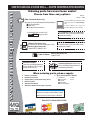
OPERATION AND PARTS MANUAL
MODEL CDM1H
HAND-HELD CORE DRILL
(ELECTRIC MOTOR)
Revision #6 (09/08/10)
To find the latest revision of this
publication, visit our website at:
www.multiquip.com
THIS MANUAL MUST ACCOMPANY THE EQUIPMENT AT ALL TIMES.
CDM1H HAND-HELD CORE DRILL — PROPOSITION 65 WARNING
Engine exhaust and some of
its constituents, and some dust created
by power sanding, sawing, grinding,
drillingandotherconstructionactivities
contains chemicals known to the State
of California to cause cancer, birth
defects and other reproductive harm.
Some examples of these chemicals are:
Leadfromlead-basedpaints.
Crystallinesilicafrombricks.
Cementandothermasonryproducts.
Arsenicandchromiumfromchemically
treatedlumber.
Your risk from these exposures varies,
depending on how often you do this type
of work. To reduce your exposure to
these chemicals: ALWAYS work in a
well ventilated area, and work with
approved safety equipment, such as
dust masks that are specially designed
to filter out microscopic particles.
PAGE 2 —CDM1H CORE DRILL — OPERATION AND PARTS MANUAL — REV. #6 (09/08/10)
CDM1H HAND-HELD CORE DRILL — SILICOSIS WARNING
WARNING
WARNING
SILICOSIS WARNING
RESPIRATORY HAZARDS
Grinding/cutting/drilling of masonry, concrete, metal and
other materials with silica in their composition may give
off dust or mists containing crystalline silica. Silica is a
basic component of sand, quartz, brick clay, granite and
numerous other minerals and rocks. Repeated and/or
substantial inhalation of airborne crystalline silica can
cause serious or fatal respiratory diseases, including
silicosis. In addition, California and some other
authorities have listed respirable crystalline silica as a
substance known to cause cancer. When cutting such
materials, always follow the respiratory precautions
mentioned above.
Grinding/cutting/drilling of masonry, concrete, metal and
other materials can generate dust, mists and fumes
containing chemicals known to cause serious or fatal
injury or illness, such as respiratory disease, cancer,
birth defects or other reproductive harm. If you are
unfamiliar with the risks associated with the particular
process and/or material being cut or the composition of
the tool being used, review the material safety data
sheet and/or consult your employer, the material
manufacturer/supplier, governmental agencies such as
OSHA and NIOSH and other sources on hazardous
materials. California and some other authorities, for
instance, have published lists of substances known to
cause cancer, reproductive toxicity, or other harmful
effects.
Control dust, mist and fumes at the source where
possible. In this regard use good work practices and
follow the recommendations of the manufacturers or
suppliers, OSHA/NIOSH, and occupational and trade
associations. Water should be used for dust
suppression when wet cutting is feasible. When the
hazards from inhalation of dust, mists and fumes cannot
be eliminated, the operator and any bystanders should
always wear a respirator approved by NIOSH/MSHA for
the materials being used.
CDM1H CORE DRILL — OPERATION AND PARTS MANUAL — REV. #6 (09/08/10) — PAGE 3
CDM1H HAND-HELD CORE DRILL — TABLE OF CONTENTS
Multiquip CDM1H
Hand-Held Core Drill
Proposition 65 Warning ............................................. 2
Silicosis Warning ....................................................... 3
Table Of Contents ..................................................... 4
Parts Ordering Procedures ....................................... 5
Safety Message Alert Symbols ................................. 6
Rules For Safe Operation ...................................... 7-9
General Information ................................................ 10
Specifications/Dimensions ...................................... 11
Engine Specifications .............................................. 10
Components............................................................ 12
Pre-Set-up .......................................................... 13-15
Operation ................................................................ 16
Maintenance ........................................................... 17
Troubleshooting ...................................................... 18
Wiring Diagram ....................................................... 19
Explanation Of Code In Remarks Column .............. 20
Suggested Spare Parts ........................................... 21
Nameplate and Decals....................................... 22-23
Core Drill Assembly ............................................ 24-27
Carrying Case/Tools/ Adapter ............................ 28-29
Specification and part number
are subject to change without
notice.
Terms and Conditions of Sale — Parts ................... 30
PAGE 4 —CDM1H CORE DRILL — OPERATION AND PARTS MANUAL — REV. #6 (09/08/10)
www.multiquip.com
CDM1H HAND-HELD CORE DRILL — PARTS ORDERING PROCEDURES
Ordering parts has never been easier!
Choose from three easy options:
Order via Internet (Dealers Only):
Best Deal!
Effective:
January 1st, 2006
If you have an MQ Account, to obtain a Username
and Password, E-mail us at: parts@multiquip.
com.
Order parts on-line using Multiquip’s SmartEquip website!
N View Parts Diagrams
N Order Parts
N Print Specification Information
To obtain an MQ Account, contact your
District Sales Manager for more information.
Use the internet and qualify for a 5% Discount
on Standard orders for all orders which include
complete part numbers.*
Goto www.multiquip.com and click on
Order Parts to log in and save!
Note: Discounts Are Subject To Change
Order via Fax (Dealers Only):
All customers are welcome to order parts via Fax.
Domestic (US) Customers dial:
1-800-6-PARTS-7 (800-672-7877)
Fax your order in and qualify for a 2% Discount
on Standard orders for all orders which include
complete part numbers.*
Note: Discounts Are Subject To Change
Order via Phone: Domestic (US) Dealers Call:
1-800-427-1244
Non-Dealer Customers:
Contact your local Multiquip Dealer for
parts or call 800-427-1244 for help in
locating a dealer near you.
International Customers should contact
their local Multiquip Representatives for
Parts Ordering information.
When ordering parts, please supply:
R
R
R
R
R
R
Dealer Account Number
Dealer Name and Address
Shipping Address (if different than billing address)
Return Fax Number
Applicable Model Number
Quantity, Part Number and Description of Each Part
R
Specify Preferred Method of Shipment:
UPS/Fed Ex
DHL
N Priority One
Truck N Ground
N Next Day
N Second/Third Day
NOTICE
All orders are treated as Standard Orders and will
ship the same day if received prior to 3PM PST.
WE ACCEPT ALL MAJOR CREDIT CARDS!
CDM1H CORE DRILL — OPERATION AND PARTS MANUAL — REV. #6 (09/08/10) — PAGE 5
CDM1H HAND-HELD CORE DRILL— SAFETY MESSAGE ALERT SYMBOLS
FOR YOUR SAFETY AND THE SAFETY OF OTHERS!
Safety precautions should be followed at all times when operating
this equipment. Failure to read and understand the Safety
Messages and Operating Instructions could result in injury to
yourself and others.
This Operation and Parts Manual has been
developed to provide complete instructions for the
safe and efficient operation of the MQ Model CDM1H
Core Drill.
Before using this core drill, ensure that the operating
individual has read and understands all instructions in this
manual.
SAFETY MESSAGE ALERT SYMBOLS
The three (3) Safety Messages shown below will inform you
about potential hazards that could injure you or others. The
Safety Messages specifically address the level of exposure
to the operator, and are preceded by one of three words:
DANGER, WARNING, or CAUTION.
DANGER
You WILL be KILLED or SERIOUSLY injured if you DO
NOT follow directions.
WARNING
You CAN be KILLED or SERIOUSLY injured if you DO
NOT follow directions.
WARNING - Respiratory Hazards
ALWAYS wear approved respiratory
protection when required.
CAUTION - Eye and Hearing Hazards
ALWAYS wear approved eye and
hearing protection.
CAUTION - Accidental Starting Hazards
ALWAYS place the core-drill's ON/OFF
switch in the OFF position when the drill
is not in use.
CAUTION - Over Speed Conditions
NEVER tamper with the factory settings
of the core drill. Personal injury and
damage to the core drill can result if
operating in speed ranges above
maximum allowable.
CAUTION - Rotating Drill Bit
Rotating drill bit can cut and
crush. Keep hands and feet
clear.
CAUTION
CAUTION
You CAN be INJURED if you DO NOT follow directions.
CAUTION - Equipment Damage Hazards
HAZARD SYMBOLS
Potential hazards associated with the operation of the MQ
Model CDM1H Core Drill will be referenced with Hazard
Symbols which appear throughout this manual, and will be
referenced in conjunction with Safety Message Alert
Symbols.
Other important messages are provided throughout this
manual to help prevent damage to your drill, other property,
or the surrounding environment.
PAGE 6 —CDM1H CORE DRILL — OPERATION AND PARTS MANUAL — REV. #6 (09/08/10)
CDM1H HAND-HELD CORE DRILL — RULES FOR SAFE OPERATION
DANGER
Read this manual!
Failure to follow instructions in this manual may lead to
serious injury or even death! This equipment is to be
operated by trained and qualified personnel only! This
equipment is for industrial use only.
The following safety guidelines should always be used when
operating the MQ Model CDM1H Core Drill.
GENERAL SAFETY
■ DO NOT operate or service this
equipment before reading this entire
manual.
■ This equipment should not be operated
by persons under 18 years of age.
■ NEVER operate this equipment without proper protective
clothing, shatterproof glasses, steel-toed boots, hard hat
and other protective devices required by the job.
■ NEVER operate this equipment when not feeling
well due to fatigue, illness or taking medicine.
■ NEVER operate this equipment under the influence of
drugs or alcohol.
■ ALWAYS wear proper respiratory (mask),
hearing and eye protection equipment when
operating the core drill.
■ Whenever necessary, replace nameplate, operation and
safety decals when they become difficult read.
■ Manufacture does not assume responsibility for any
accident due to equipment modifications.
■ NEVER use accessories or attachments, which are not
recommended by Multiquip for this equipment. Damage
to the equipment and/or injury to user may result.
■ NEVER operate the core drill in an
explosive atmosphere or near combustible
materials.The electric motor of this coredrill emits sparks during operation and
shut-down. A explosion or fire could result
causing severe bodily harm or even death if the sparks
make contact with combustibe or explosive materials.
■ Maintain this equipment in a safe operating condition at
all times.
■ Keep bystanders, children and vistors away while
operating the core drill. Distractions can cause you to
loose control.
■ DO NOT wear wear loose clothing or jewelry. Contain
long hair. Keep your hair, clothing, and gloves away from
moving parts.
■ ALWAYS store equipment properly when it is not being
used. Equipment should be stored in a clean, dry location
out of the reach of children.
■ ALWAYS be sure the operator is familiar with proper
safety precautions and operation techniques before using
core drill.
■ ALWAYS keep work area clean and free of foreign matter
and debris. Also keep work area well lit.
■ Avoid accidental starting. Make sure power ON/OFF
switch is off before applying power. Carrying the coredrill with your finger on the power switch invites accidental
starting.
■ NEVER leave the core drill unattended. When not in use
always unplug the core drill from power source.
■ ALWAYS remove any adjusting keys or wrenches before
turing the core drill on. A wrench or key that is left attached
to the rotating part of the core drill may result in personal
injury.
■ DO NOT overreach. Keep proper footing and balance at
all times. Proper footing and balance enables better
control of the core drill in unexpected situations.
■ Keep all inexperienced and unauthorized people away
from the equipment at all times.
■ Become familiar with the components of the core drill
before operating.
■ ALWAYS replace any worn or damaged warning decals.
■ NEVER touch drill bit cutting edges during operation. Also
allow drill bit a sufficient amount of time to cool before
touching.
CDM1H CORE DRILL — OPERATION AND PARTS MANUAL — REV. #6 (09/08/10) — PAGE 7
CDM1H HAND-HELD CORE DRILL — RULES FOR SAFE OPERATION
■ Maintain the core drill and drill bits with care. Keep drill
bits sharp. Sharp cutting edges are less likely to bind.
■ If drilling into a workpiece that is unattached, use clamps
or other means to secure the workpiece so that it will not
move. NEVER hold the workpiece by hand or againist
your body.
■ Use this core drill only for its intended purpose. DO NOT
use this core drill for applications not recommended.
■ Inspect the drill after each use. Replace any damaged or
worn parts immediately. DO NOT use a defective coredrill.
■ NEVER point the core drill at anyone in the area when
operating.
■ ALWAYS hold the core drill firmly with both hands when
drilling.
■ NEVER cover the air vents on the body of the core drill.
ALWAYS leave these vents exposed. These vents are
essential for the cooling of the electric motor. NEVER
place tape over the vent to keep out dust.
■ If a malfunction occurs, immediately unplug the core drill
from the power source and correct the problem. If the
problem can not be corrected, contact your nearest MQ
service center.
■ DO NOT force your core drill. Excerting excessive force
while drilling will damage your machine and is hazardous.
■ ALWAYS make sure drill bits are installed securely so
that it will slip or fall out. It is hazardous to use a core
drill with a loose fitted drill bit.
■ Some materials contain chemicals which may be
toxic.Take precautions to prevent dust inhalation and skin
contact.
ELECTRICAL SAFETY
■ ALWAYS test the ON/OFF switch on the core drill before
operating. The purpose of this switch is to shut down the
electric motor.
■ NEVER use a extension cord that is frayed or damaged
where the insulation has been cut.
■ NEVER carry the core drill by its power cord or disconnect
it by yanking the cord from the power outlet.
■ ALWAYS make certain that the proper extension cord
has been selected for the job. See Table 4.
■ NEVER allow power cord to lay in water.
■ NEVER stand in water while operating the core drill.
■ DO NOT walk around with a plugged in core drill. The
possibility exist of your finger accidently hitting the power
ON/OFF switch, causing severe bodily harm or even
death.
■ When connecting the core drill to a power receptacle,
make sure the receptacle circuit is connected to either a
GFCI receptacle or a receptacle protected by a 20 amp
circuit breaker.
■ When plugging the core-drill into a power receptacle, check
the nameplate for the correct operating voltage. Operating
the core drill at the wrong voltage will damage the electric
motor. ALWAYS read the nameplate before applying
power.
■ This core drill is equipped with a 3-prong male power
plug. DO NOT use a 2-prong adapter when plugging into
a wall outlet. This will defeat the purpose of the ground
circuit. If the plug does not fit into the receptacle, contact
a qualified electrician to install a 3-conductor wall
receptacle (outlet).
■ Avoid body contact with grounded surfaces such as pipes,
radiators, ranges and refrigerators. There is an increased
risk of electrical shock if your body is grounded.
■ DO NOT expose the the core drill to rain or wet conditions.
Water entering the drill wii increase the risk of electrical
shock.
■ When operating the core drill outside, be sure to use the
apporpriate outdoor extension cord. This type of extension
cord reduces the risk of electrical shock.
■ ALWAYS hold core drill by its insulated gripping handle
when performing work. The possibility exists of the drill
bit making contact with hidden wiring or its own cord.
Contact with a "live" wire can cause electrical shock to
the operator.
■ ALWAYS remove the AC power cord from the power
source before performing any service or maintenance on
the core drill. This preventative safety measure reduces
the possibility of accendental starting.
PAGE 8 —CDM1H CORE DRILL — OPERATION AND PARTS MANUAL — REV. #6 (09/08/10)
CDM1H HAND-HELD CORE DRILL — RULES FOR SAFE OPERATION
TRANSPORTING
■ ALWAYS place the core drill inside its carrying case when
work has been completed.
■ ALWAYS wrap power cord neatly to avoid damage.
■ ALWAYS place wrenches back into carrying case when
work has been completed.
MAINTENANCE
■ NEVER lubricate components or attempt service on a
running core drill.
■ ALWAYS allow the core drill a proper amount of time to
cool before servicing.
■ Keep the core drill in proper running condition.
■ Fix damage to the core drill immediately and always
replace broken parts. Replace with only MQ
recommended parts.
EMERGENCIES
■ ALWAYS know the location of the nearest fire
extinguisher and first aid kit.
■ In emergencies always know the location of the
nearest phone or keep a phone on the job site.
Also know the phone numbers of the nearest
ambulance, doctor and fire department. This
information will be invaluable in the case of an
emergency.
CDM1H CORE DRILL — OPERATION AND PARTS MANUAL — REV. #6 (09/08/10) — PAGE 9
CDM1H HAND-HELD CORE DRILL — GENERAL INFORMATION
APPLICATION
COBRA BIT (M18) SET-UPS – up to 5-in. dia.
The MQ CDM1H Hand-Held Core Drill is designed to be
used for either dry or wet drilling applications involving concrete type materials. Up to 3-inch (76.2 mm) diameter holes
can be drilled for wet drilling applications using standard
MQ drill bits or 5-1/8 inch (130 mm) diameter holes for wet
or dry applications using the Cobra™ drill bits.
Power Plant
1
2
1
12
2
The MQ CDM1H is powered by a 115 VAC electric motor @12
amps. Maximum RPM's is 2200 . The unit weighs 9.0 lbs (3.35 kg.)
Features
The CDM1H kit comes as follows:
■ Hand-Held Core Bit Power Drill
■ Carrying Case
■ Two Core Bit Adapters
■ Detachable Threaded Handle
■ Water Kit
■ Tools for Core Bit Connection/Removal
■ Operation and Parts Manual
BLOCKBUSTER (5/8-in. - 11F) SET-UPS – up to 5-in. dia.
1
6
10
13
3
1
6
3
Cobra™ Drill Bits (Wet and Dry)
The Cobra™ drill bits are engineered to drill through reinforced
concrete with or without water. These bits are available in 6 or 10
inch (15.24- 25.4 cm.) drilling depths and range in diameter
from 1 to 5 inches (25 to 127 mm.).
WET BITS 5/8-in. - 11F THREAD – up to 3-in. dia.
1
6
Standard MQ Drill Bits (Wet)
10
13
This core drill can use the following series of wet drilling bits:
■
■
■
■
■
GCB Series –
GB Series –
PRB Series –
PCB Series –
PCB Series –
economy quality small jobs.
standard quality small to mid-size jobs.
premium quality for fast speeds.
super premimum quality and long life.
pro quality, high steel content and
extremely hard aggregate small jobs.
Threads/Adapters and Core Bit Combinations
Figure 1 and Table 1 depict most Adapter/Core Bit
combinations and part numbers. The CDM1H is
manufactured with an 18mm male drive end that directly
connects to all MQ COBRA™ drill bits. For other US standard
threading options, the CDM1H includes two adapters: (1)
ADM1858 – that permits connection of 5/8”-11 female
threaded bits, and (2) ADM181147 – that permits connection
of 1 ¼”-7 female threaded bits. All other adapters/extensions
are available as optional part items.
1
4
6
4
WET BITS - 1-1/4 - 7 THREAD – up to 3-in. dia.
(Non-COBRA Bits)
1
7
11
14
5
1
7
5
Figure 1. Threads/Adapters and Core Bit Combinations
PAGE 10 —CDM1H CORE DRILL — OPERATION AND PARTS MANUAL — REV. #6 (09/08/10)
CDM1H HAND-HELD CORE DRILL — SPECIFICATIONS/DIMENSIONS
Table 1. Threads/Adapters and Core Bit Combinations
Table 2. Specifications
Description
Model
CDM1H
Handheld Core Drill (18 mm)
Motor
115 VAC, 60 Hz @
2200 RPM
2
Drill Bits, Dry, COBRA 18 mmF Thread
Current
3
Drill Bits, Dry, Blockbuster, 5/8"-11F Thread
Watts
4
Drill Bits, Wet, 5/8"-11F Thread
Applicable Drill Bit Diameter
Standard Drill Bits
1 inch
(25 mm)
5
Drill Bits, Wet, 1 1/4"-7F Thread
Applicable Drill Bit Diameter
Cobra™ Drill Bits
1 inch to 5 inches
(25-127 mm)
Dry Net Weight
8.81 lbs. (4 Kg.)
Item Part Number
1
CDM1H
6
ADM1858
Adapter, M18 Female to 5/8"-11 Male
7
ADM181147
Adapter, M18 Female to 1 1/4"-7 Male
8
AD114758
Adapter, 1 1/4"-7 Female to 5/8"-11 Male
(part not shown)
9
AD581147
Adapter, 5/8"-11 Female to 1 1/4"-7 Male
(part not shown)
10
EXT65811
Extension, 6" x 5/8"-11 Female/Male
11
EXT61147
Extension, 6" x 1 1/4"-7 Female/Male
12
EXT12M18
Extension, 12"xM18 Female/Male
13
EXT125811
Extension, 12", 5/8"-11 Female/Male
14
EXT121147
Extension, 12", 1 1/4"-7 Female/Male
Contact the MQ Sales Department for the core
drill that best fits your application.
12 amps
1,350
Figure 2. CDM1H Core Drill Dimensions
Table 3. Dimensions
A (Length)
22.25 in.
(572 mm)
B (Height)
11.00 in.
(279 mm)
C (Width)
10.5 in.
(267 mm)
CDM1H CORE DRILL — OPERATION AND PARTS MANUAL — REV. #6 (09/08/10) — PAGE 11
CDM1H HAND-HELD CORE DRILL — COMPONENTS
9
7
8
10
12
11
6
5
4
27
3
2
1
M
M
L
B
AH
T
S NC
U
J E
D R
AW
E
16
17 11 14
18
13
15
Figure 3. CDM1H Components
20
1.
2.
3.
4.
5.
6.
7.
8.
9.
Hand-Grip – The CDM1H uses a plastic hand grip to
guard against possible electric shock. When drilling,
hold this grip firmly.
Reset Button – In the event of an overload press this
button. Allow a sufficient amount of time for the electric
motor (windings) to cool down before pressing the reset
button.
Electric Motor Brush Covers (2) – Insert tip of a flat
blade screwdriver into slot on brush cover, turn counterclockwise and remove cover to gain access to brushes.
Stock Release Adjustment Screw – This screw
provided tension for the trigger release spring. Adjust
the screw for the desire amount of spring tension.
Adjustable Stock – This stock slides back and forth
and is adjustable. It is provided for operator comfort.
Stock Release Lever – To release the stock and set
in position. Squeeze trigger lever and hold, pull back
and set in desired position, then release lever.
Rubber Shoulder Pad – Place this pad against your
shoulder or other parts of your body when drilling. Its
purpose is to reduce shock and vibration.
Drill Body –The electric motor and associated
components are contain inside the drill body.
AC Power Cord – Plug this 16 ft. (4.87 meters) power
cord into a 115 VAC grounded type receptacle. NEVER
remove the ground pin from the plug. This will defeat
10.
11.
12.
13.
14.
15.
16.
17.
18.
19
the ground circuit and greatly increase the possibility
of electrical shock.
Detachable Rubber Handle – Insert the detachable
rubber handle into the desired port. Tighten securely.
Handle Port – The CDM1H has 3 handle ports.
Wrenches – These wrenches (27 mm and adjustable)
are used to install and remove the core drill bits.
Main Shaft – Attach core drill bit to this shaft.
Water Shut-off Valve – Turn this valve downward to let
water flow and up to stop.
Water Tube/Adapter – Connect this tube/adapter to a
water source. Typically a garden hose.
Grease Plug– Using a 5 mm hex wrench, remove this
plug to add lubrication grease. DO NOT over fill.
ON/OFF Trigger– Squeeze this trigger to start the drill,
and release to stop.
Core Drill Bit– Place bit onto main shaft and tighten
securely. Contact MQ sales department for the core
drill bit that best fits your application.
19. Adapter – 1-1/4" X 7 female to 18 mm male thread for wet
drilling bits from 1-1/2 inch diameter and above.
20. Adapter – M18 female to 5/8"-11 male.
PAGE 12 —CDM1H CORE DRILL — OPERATION AND PARTS MANUAL — REV. #6 (09/08/10)
CDM1H HAND-HELD CORE DRILL — PRE-SETUP
Before Starting:
CAUTION - Read Manual
Before attempting to operate
this core drill, and to avoid
serious injury to personnel,
always read and understand
operation manual. Failure to
read and understand operation
manual could result in serious
harm or even death!
DANGER - Flammable/Combustible Materials
NEVER operate the core drill in or around
flammable materials. The core drill emits
sparks, if contact is made between the
sparks and the flammable material,the
posibility exists of fire or explosion causing
damage to the equipment and severe bodily
harm even death!
Warning - Toxic Fumes
NEVER operate the core drill in a confined
or enclosed area structure that does not
provide ample free flow of air.
Drilling With Standard DRY/WET Core Bits
With the proper adapter, 1" to 3" diameter dry/wet core bits can
be used with the CDM1H when drilling vertical and horizontal
holes. All hand-held core drills require practice and operator
technique to ensure consistent clean drilled holes. When using
wet core bits, water MUST be used to ensure proper cooling.
“Bit chatter” around the hole can be eliminated by various
techniques such as angle-entry procedures and fabricated
guides. Angle-entry is one safe and simple way to start the bit
onto the surface. Angle the bit (1) at 10°-15° above the surface
and slowly introduce the bit until it is flush with the surface (2).
See Figure 5.
Drilling with a MQ Cobra™ Bit
The drilling of clean holes with Cobra™ core bits (1) requires an
operating technique utilizing the center drill bit adapter (2). Center
drill bit adapters are included with the core bit. As bits wear out,
this adapter may be used with future core bits of similar depth
and diameter. The adapter bit permits an anchoring point (3) so
the bit can be accurately introduced into the surface (4). Once
the hole is started, the center drill bit adapter (2) must be removed.
See Figure 4.
Figure 5. Drilling with a Standard DRY/WET Core Bit
Figure 4. Drilling with a MQ Cobra™ Bit
CDM1H CORE DRILL — OPERATION AND PARTS MANUAL — REV. #6 (09/08/10) — PAGE 13
CDM1H HAND-HELD CORE DRILL — PRE-SETUP
Attaching the Cobra™ Core Bit to the Core Drill
Connecting Water to the Core Drill
1. Place the core bit and core drill on a suitable workbench or
area that is free of clutter dirt and debris.
1. Attach the supplied water hose and garden hose fitting to the
core drill as shown in Figure 5. Be sure to place worm-clamps
on each end of the hose to prevent leaking.
2. Before installing the core bit make sure that thepower cord
of the core drill is unplugged from the AC wall receptacle.
NEVER install the core bit on core drill that has power applied
to it.
3. Screw the core bit onto the main shaft of the core drill by
turning it clockwise by hand until tight (Figure 4).
4. Using the supplied wrenches ( 27 mm and adjustable)
continue to tighten the core bit. When using the wrenches,
apply pressure in the opposite direction to fully tighten.
5. Insert the detachable handle into the desired handle port.
Figure 7. Connecting the Water
Adjusting the Stock (Shoulder Rest)
1. The CDM1H is supplied with an adjustable stock.This stock
can be adjusted by simply squeezing the trigger and sliding
the stock back and forth to the desired position Figure 6).
2. If more spring tension is required (trigger lever), simply adjust
the spring tension bolt until the desired spring tension is
obtained.
Figure 6. Attaching the Cobra™ Core Bit to the Core Drill
With the proper adapter, 1" to 3" diameter dry/
wet core bits can be used with the CDM1H when
drilling vertical and horizontal holes. See
General Information section. Different size
wrenches may be required depending on the
type of the core bit lug.
Figure 8. Adjusting the Stock
PAGE 14 —CDM1H CORE DRILL — OPERATION AND PARTS MANUAL — REV. #6 (09/08/10)
CDM1H HAND-HELD CORE DRILL — PRE-SETUP
Applying Power to the Core Drill
DANGER - ELECTROCUTION HAZARDS
1. This core drill requires 115 VAC, 60 Hz power. Applying
power to the drill that is not specified will cause severe
damage to the core drill. Always read serial plate tag
before applying power to the core drill.
During operation of this core drill, there
exists the possibility of electrocution,
electrical shock or burn, which can cause
severe bodily harm or even DEATH!
2. The power plug on this core drill is a 3-prong grounded
type plug. ALWAYS connect this plug to a 3-prong
grounded receptacle. NEVER plug this device into a 2prong type receptacle. This will defeat the ground circuit.
The use of a 3-prong to 2-prong adapter is strictly
prohibited.
To avoid these hazards:
Warning - Accidental Starting
NEVER use damaged or worn cables when plugging the
core drill into an AC power receptacle.
NEVER stand in water and touch a
live power cord.
To avoid accidental starting, ALWAYS
keep fingers away from the power OFF/
ON switch when applying power.
POWER
CORD
(POWER ON)
Table 4. Cable Selection (60 Hz, Single Phase Operation)
Current in
Amperes
3. Connect the core drill's AC power cord to a 115 VAC wall
receptacle (Figure 7) that is protected by a 20 amp
circuit breaker. For best results connect the power cord
to a GFCI receptacle.
WET
HANDS
NEVER grab or touch a live power
cord with wet hands.
Load In
Watts
Maximum Allowable Cable Length
At 120
Volts
#10 Wire
#12 Wire
#14 Wire
#16 Wire
2.5
300
1000 ft.
600 ft.
375 ft.
250 ft.
5
600
500 ft.
300 ft.
200 ft.
125 ft.
7.5
900
350 ft.
200 ft.
125 ft.
100 ft.
10
1200
250 ft.
150 ft.
100 ft.
15
1800
150 ft.
100 ft.
65 ft.
20
2400
125 ft.
75 ft.
50 ft.
CAUTION: Equipment damage can result from low voltage.
Figure 9. Connecting the Power
CDM1H CORE DRILL — OPERATION AND PARTS MANUAL — REV. #6 (09/08/10) — PAGE 15
CDM1H HAND-HELD CORE DRILL — OPERATION
Before Operating
1. Place the valve on the water source to the ON position, and
then turn the water valve on the core drill (Figure 8) to the
ON position (down). Verify that water is flowing smoothly
and evenly.
Warning - Binding of Output Shaft
This core drill can whip violently if it comes in contact with
rebar or coarse material which would cause the shaft to
bind. Be extremely careful at all times when drilling. The
possibility exists of the core drill severely twisting the wrist
or striking the body with excessive force.
ALWAYS drill with uniform pressure and keep
the bit straight. When drilling through steel
rebar, reduce the pressure to avoid overloading
the motor.
Figure 10. Water Valve (ON Position)
2. If water is not flowing, check all connections and correct the
problem.
3. Place the core drill against the surface (Figures 9 and 10) to
be drilled. Hold drill firmly, and squeeze the power ON/OFF
switch to begin drilling.
NEVER use the adjustable shoulder stock to
pull the bit out of the ground if the bit gets stuck
in the hole.
ALWAYS be on the lookout for exposed wiring
or buried electrical connections when drilling.
Figure 11. Wall Drilling Application
DO NOT overreach. Keep proper footing and
balance at all times. Proper footing and
balance enables better control of the core drill
in unexpected situations.
Figure 12. Floor Drilling Application
PAGE 16 —CDM1H CORE DRILL — OPERATION AND PARTS MANUAL — REV. #6 (09/08/10)
CDM1H HAND-HELD CORE DRILL — SHUTDOWN/MAINTENANCE
Shutdown
Maintenance
1. Remove the power cord from the wall receptacle or power
source.
1. The CDM1H basically is maintenance-free. The only
maintenance requirement is to periodically check the main
gear grease level.
2. Using the supplied 5 mm allen wrench, remove the grease
plug as shown in Figure11.Figure 8. Wall Application
3. Visually inspect to see if grease is present. It may be
necessary to insert a small blade screw driver or similar
device into the filler hole to determine if the grease level is
low.
4. If the grease level is low, apply 1 shot of lithium base grease,
grade N0.1. DO NOT over fill.
5. Reinstall grease plug and tighten securely.
2. Allow a sufficient amount of time for the core drill bit to cool
before attempting to remove it from the core drill.
3. Using the wrenches as illustrated in Figure 4, remove the
core drill bit from the drill.
4. Clean the drill bit with a mild cleaning solution, removing
dirt and foreign matter.
5. Once the core drill has been cleaned, place the core drill
into its carrying case along with all associated hardware. Be
sure to wrap the power cord neatly into the carrying case.
This will extend the life of the cord.
6. Store the carrying case out of the reach of children, in a
location that is moisture free.
Figure 13. Main Gear Lubrication
CDM1H CORE DRILL — OPERATION AND PARTS MANUAL — REV. #6 (09/08/10) — PAGE 17
CDM1H HAND-HELD CORE DRILL — TROUBLESHOOTING
TABLE 4. CORE DRILL TROUBLESHOOTING
SYMPTOM
POSSIBLE PROBLEM
SOLUTION
Steel bar or stone, etc. is
caught between core and BIT.
Immediate turn SWITCH OFF.
Excessive wear, bit tip has
become flush with shank.
Try to rotate BIT in both directions using spanner to lift it out.
Bit is stuck.
Replace BIT.
Drilling is slow in normal
operation.
Waste water is contaminated
with steel chip, DRILL is cutting
rebar.
Immediately check the waster water. Adjust the pressure on so as
not to overload MOTOR.
Bit is worn.
Immediately check BIT for abrasion. Replace BIT.
Diamond is not exposed on TIP
surface.
Immediately check BIT for abrasion. Dress BIT.
Chips are deposited on BIT
surface.
Steel chips are scorched on BIT
surface.
Immediately check BIT for abrasion. Increase water feed pressure.
Dress or Brush BIT with a wire.
Immediately check BIT for abrasion. Remove steel chips.
PAGE 18 —CDM1H CORE DRILL — OPERATION AND PARTS MANUAL — REV. #6 (09/08/10)
CDM1H HAND-HELD CORE DRILL — WIRING DIAGRAM
CDM1H CORE DRILL — OPERATION AND PARTS MANUAL — REV. #6 (09/08/10) — PAGE 19
CORE DRILL — EXPLANATION OF CODE IN REMARKS COLUMN
The following section explains the different symbols and
remarks used in the Parts section of this manual. Use the
help numbers found on the back page of the manual if there
are any questions.
NOTICE
The contents and part numbers listed in the parts
section are subject to change without notice. Multiquip
does not guarantee the availability of the parts listed.
SAMPLE PARTS LIST
NO.
1
2%
2%
3
4
PART NO. PART NAME
QTY. REMARKS
12345
BOLT......................1 .....INCLUDES ITEMS W/%
WASHER, 1/4 IN............NOT SOLD SEPARATELY
12347
WASHER, 3/8 IN....1 .....MQ-45T ONLY
12348
HOSE ..................A/R ...MAKE LOCALLY
12349
BEARING ..............1 .....S/N 2345B AND ABOVE
NO. Column
QTY. Column
Numbers Used — Item quantity can be indicated by a
number, a blank entry, or A/R.
A/R (As Required) is generally used for hoses or other
parts that are sold in bulk and cut to length.
A blank entry generally indicates that the item is not sold
separately. Other entries will be clarified in the “Remarks”
Column.
REMARKS Column
Some of the most common notes found in the “Remarks”
Column are listed below. Other additional notes needed
to describe the item can also be shown.
Assembly/Kit — All items on the parts list with the
same unique symbol will be included when this item is
purchased.
Unique Symbols — All items with same unique
symbol
Indicated by:
“INCLUDES ITEMS W/(unique symbol)”
(@, #, +, %, or >) in the number column belong to the
same assembly or kit, which is indicated by a note in the
“Remarks” column.
Serial Number Break — Used to list an effective serial
number range where a particular part is used.
Duplicate Item Numbers — Duplicate numbers indicate
multiple part numbers, which are in effect for the same
general item, such as different size saw blade guards in
use or a part that has been updated on newer versions
of the same machine.
NOTICE
When ordering a part that has more than one item
number listed, check the remarks column for help in
determining the proper part to order.
PART NO. Column
Numbers Used — Part numbers can be indicated by a
number, a blank entry, or TBD.
TBD (To Be Determined) is generally used to show a
part that has not been assigned a formal part number
at the time of publication
Indicated by:
“S/N XXXXX AND BELOW”
“S/N XXXX AND ABOVE”
“S/N XXXX TO S/N XXX”
Specific Model Number Use — Indicates that the part
is used only with the specific model number or model
number variant listed. It can also be used to show a
part is NOT used on a specific model or model number
variant.
Indicated by:
“XXXXX ONLY”
“NOT USED ON XXXX”
“Make/Obtain Locally” — Indicates that the part can
be purchased at any hardware shop or made out of
available items. Examples include battery cables, shims,
and certain washers and nuts.
PAGE 20 —CDM1H CORE DRILL — OPERATION AND PARTS MANUAL — REV. #6 (09/08/10)
CDM1H HAND-HELD CORE DRILL — SUGGESTED SPARE PARTS
CDM1H Hand Held Core Drill
1 to 5 Units
Qty. ..... P/N ......................... Description
2 ......... CD101534 ............... CARBON BRUSH
2 ......... CD101560 ............... POWER CORD
2 ......... CD101551 ............... POWER SWITCH
2 ......... CD101552 ............... CIRCUIT BREAKER
1 ......... AD114F58M ........... ADAPTER, 5/8"-11 MALE THREAD
CDM1H CORE DRILL — OPERATION AND PARTS MANUAL — REV. #6 (09/08/10) — PAGE 21
CDM1H HAND-HELD CORE DRILL — NAMEPLATE AND DECALS
NAMEPLATE AND DECALS
PAGE 22 —CDM1H CORE DRILL — OPERATION AND PARTS MANUAL — REV. #6 (09/08/10)
CDM1H HAND-HELD CORE DRILL — NAMEPLATE AND DECALS
NAMEPLATE AND DECALS
NO.
1
2
PART NO.
DCL701
DCL700
PART NAME
DECAL: MODEL INFORMATION
DECAL: CAUTION CLEAN WATER
QTY.
1
1
REMARKS
CDM1H CORE DRILL — OPERATION AND PARTS MANUAL — REV. #6 (09/08/10) — PAGE 23
CDM1H HAND-HELD CORE DRILL — CORE DRILL ASSY.
CORE DRILL ASSY.
68
OLD STYLE
NEW STYLE
PAGE 24 —CDM1H CORE DRILL — OPERATION AND PARTS MANUAL — REV. #6 (09/08/10)
CDM1H HAND-HELD CORE DRILL — CORE DRILL ASSY.
CORE DRILL ASSY.
NO.
1
2
3
4
5
6
7
8
9
10
11
12
13
14
15
16
17
18
19
20
21
22
23
24
25
26
27
28
29
30
31
32
33
34
35
36
37
38
39
40
41
42
43
44
PART NO.
CD101501
CD101502
CD101503
CD101503
CD101505
CD101506
CD101507
CD101508
CD101509
CD101510
CD101511
CD101512
CD101513
CD101514
CD101515
CD101516
CD101517
CD101518
CD101519
CD101520
CD101521
CD101522
CD101523
CD101524
CD101525
CD101526
CD101527
CD101528
CD101529
CD101530
CD101531
CD101532
CD101533
CD101534
CD101535
CD101536
CD101537
CD101538
CD101539
CD101540
CD101541
CD101542
CD101543
CD101544
PART NAME
GEAR CASE
MAIN SHAFT
SEAL
SEAL
BEARING, 6003LLU
BEARING, 6003ZZ
SNAP RING, R35
SNAP RING, S17
SNAP RING, S9
PLATE
FRICTION PLATE
METAL COLLAR
FIRST GEAR
DISK SPRING
FINE U-NET
BEARING, 608ZZ
DIAPHRAGM
O-RING
BEARING, 609LLU
ARMATURE
BEARING, 608ZZ
FILLING RING
FIELD
SCREW, 3/16 X 2-1/2"
SPRING WASHER, M5
NUT, M5
BEARING
SECOND PINION
WOODRUFF KEY
SECOND GEAR
MOTOR HOUSE
BRUSH TUBE
SCREW, M5
CARBON BRUSH
BRUSH CAP
SCREW, M5
SPRING WASHER, M5
TELESCOPING TUBE
SCREW, 5/32 X 5/8"
NUT, M5
HOLDER
TELESCOPING TUBE
HOLDER
SCREW, 1/8"
QTY.
1
1
1
2
1
1
1
1
1
2
2
1
1
2
1
3
1
1
1
1
1
1
1
2
2
2
2
1
1
1
1
2
2
2
2
4
4
1
4
4
1
1
1
1
REMARKS
CDM1H CORE DRILL — OPERATION AND PARTS MANUAL — REV. #6 (09/08/10) — PAGE 25
CDM1H HAND-HELD CORE DRILL — CORE DRILL ASSY.
CORE DRILL ASSY.
68
OLD STYLE
NEW STYLE
PAGE 26 —CDM1H CORE DRILL — OPERATION AND PARTS MANUAL — REV. #6 (09/08/10)
CDM1H HAND-HELD CORE DRILL — CORE DRILL ASSY.
CORE DRILL ASSY. (CONTINUED)
NO.
45
46
47
48
49
50
50
51
51
52
53
54
55
56
57
58
59
60
61
62
63
64
65
66
67
68
PART NO.
CD101545
CD101546
CD101547
CD101548
CD101549
CD101550
CD101576
CD101551
CD101577
CD101552
CD101553
CD101554
CD101555
CD101556
CD101557
CD101558
CD101559
CD101560
CD101561
CD2704006
CD101563
CD101564
CD101569
CD101570
CD101571
CD101608
PART NAME
QTY.
REMARKS
SPRING
1
SHIFTER
1
SCREW, M6
1
NUT, M6
2
SCREW, M6
1
SWITCH BOX .............................................................. 1 .......... OLD STYLE
SWITCH BOX W/ LOCK BUTTON HOLE ..................... 1 .......... NEW STYLE
POWER SWITCH ........................................................ 1 .......... OLD STYLE
POWER SWITCH W/ SPEED LOCK BUTTON ............ 1 .......... NEW STYLE
CIRCUIT BREAKER
1
WASHER
1
CABLE FIX PLATE
1
SCREW, 5/32 X1/2"
2
SCREW, 5/32 X 1-1/2"
4
SCREW, M4
2
EARTH CABLE
1
CABLE WIRE
1
POWER CORD
1
FEMALE QUICK DISCONNECT
1
WATER COCK
1
HANDLE
1
PLUG
1
HOSE CLAMP
2
PLASTIC WATER HOSE, 4-INCH
1
FITTING, BRASS BARB 3/4 X 3/8"
1
BAFFLE
1
CDM1H CORE DRILL — OPERATION AND PARTS MANUAL — REV. #6 (09/08/10) — PAGE 27
CDM1H HAND-HELD CORE DRILL —CARRYING CASE /TOOLS/ADAPTER
CARRYING CASE/TOOLS ADAPTER
7
2
3
TOOL
KIT
5
4
6
PAGE 28 —CDM1H CORE DRILL — OPERATION AND PARTS MANUAL — REV. #6 (09/08/10)
CDM1H HAND-HELD CORE DRILL —CARRYING CASE /TOOLS/ADAPTER
CARRYING CASE/TOOLS ADAPTER
NO.
2
*
3
*
4
*
5
*
6
*
7
PART NO.
101566
101567
101568
CD101572
ADM1858
CD101575
PART NAME
QTY.
REMARKS
27 MM WRENCH
1
ADJUSTABLE WRENCH
1
5 MM ALLEN WRENCH
1
ADAPTER, 1-1/4" X 7
1
ADAPTER, M18 FEMALE to 5/8"-11 MALE
1
TOOL KIT ..................................................................... 1 .......... INCLUDES ITEMS W/
CDM1H CORE DRILL — OPERATION AND PARTS MANUAL — REV. #6 (09/08/10) — PAGE 29
*
TERMS AND CONDITIONS OF SALE —PARTS
PAYMENT TERMS
5.
Parts must be in new and resalable
condition, in the original Multiquip
package (if any), and with Multiquip part
numbers clearly marked.
6.
The following items are not returnable:
Multiquip reserves the right to quote and
sell direct to Government agencies, and to
Original Equipment Manufacturer accounts
who use our products as integral parts of their
own products.
a.
SPECIAL EXPEDITING SERVICE
Terms of payment for parts are net 30 days.
FREIGHT POLICY
All parts orders will be shipped collect or
prepaid with the charges added to the invoice.
All shipments are F.O.B. point of origin.
Multiquip’s responsibility ceases when a
signed manifest has been obtained from the
carrier, and any claim for shortage or damage
must be settled between the consignee and
the carrier.
b.
MINIMUM ORDER
The minimum charge for orders from Multiquip
is $15.00 net. Customers will be asked for
instructions regarding handling of orders not
meeting this requirement.
RETURNED GOODS POLICY
Return shipments will be accepted and
credit will be allowed, subject to the following
provisions:
1.
2.
A Returned Material Authorization
must be approved by Multiquip prior to
shipment.
Obsolete parts. (If an item is in the
price book and shows as being
replaced by another item, it is
obsolete.)
Any parts with a limited shelf life
(such as gaskets, seals, “O” rings,
and other rubber parts) that were
purchased more than six months
prior to the return date.
c.
Any line item with an extended
dealer net price of less than
$5.00.
d.
Special order items.
e.
Electrical components.
f.
Paint, chemicals, and lubricants.
g.
Decals and paper products.
h.
Items purchased in kits.
7.
The sender will be notified of any material
received that is not acceptable.
To obtain a Return Material Authorization,
a list must be provided to Multiquip
Parts Sales that defines item numbers,
quantities, and descriptions of the items
to be returned.
8.
Such material will be held for five
working days from notification, pending
instructions. If a reply is not received
within five days, the material will be
returned to the sender at his expense.
a.
The parts numbers and descriptions
must match the current parts price
list.
9.
b.
The list must be typed or computer
generated.
Credit on returned parts will be issued
at dealer net price at time of the original
purchase, less a 15% restocking
charge.
c.
The list must state the reason(s)
for the return.
d.
The list must reference the sales
order(s) or invoice (s) under
which the items were originally
purchased.
e.
The list must include the name
and phone number of the person
requesting the RMA.
3.
A copy of the Return Material Authorization
must accompany the return shipment.
4.
Freight is at the sender’s expense. All
parts must be returned freight prepaid to
Multiquip’s designated receiving point.
10. In cases where an item is accepted, for
which the original purchase document
can not be determined, the price will be
based on the list price that was effective
twelve months prior to the RMA date.
A $35.00 surcharge will be added to the
invoice for special handling including bus
shipments, insured parcel post or in cases
where Multiquip must personally deliver the
parts to the carrier.
LIMITATIONS OF SELLER’S LIABILITY
Multiquip shall not be liable hereunder for
damages in excess of the purchase price of
the item with respect to which damages are
claimed, and in no event shall Multiquip be
liable for loss of profit or good will or for any
other special, consequential or incidental
damages.
LIMITATION OF WARRANTIES
No warranties, express or implied, are
made in connection with the sale of parts or
trade accessories nor as to any engine not
manufactured by Multiquip. Such warranties
made in connection with the sale of new,
complete units are made exclusively by a
statement of warranty packaged with such
units, and Multiquip neither assumes nor
authorizes any person to assume for it
any other obligation or liability whatever in
connection with the sale of its products. Apart
from such written statement of warranty,
there are no warranties, express, implied or
statutory, which extend beyond the description
of the products on the face hereof.
Effective: February 22, 2006
11. Credit issued will be applied to future
purchases only.
PRICING AND REBATES
Prices are subject to change without prior
notice. Price changes are effective on a
specific date and all orders received on or
after that date will be billed at the revised price.
Rebates for price declines and added charges
for price increases will not be made for stock
on hand at the time of any price change.
PAGE 30 —CDM1H CORE DRILL — OPERATION AND PARTS MANUAL — REV. #6 (09/08/10)
NOTES
CDM1H CORE DRILL — OPERATION AND PARTS MANUAL — REV. #6 (09/08/10) — PAGE 31
OPERATION AND PARTS MANUAL
HERE’S HOW TO GET HELP
PLEASE HAVE THE MODEL AND SERIAL
NUMBER ON-HAND WHEN CALLING
UNITED STATES
Multiquip Corporate Office
18910 Wilmington Ave.
Carson, CA 90746
Contact: [email protected]
MQ Parts Department
Tel. (800) 421-1244
Fax (800) 537-3927
Mayco Parts
800-427-1244
310-537-3700
Fax: 800-672-7877
Fax: 310-637-3284
Warranty Department
800-306-2926
310-537-3700
Fax: 800-672-7877
Fax: 310-637-3284
Service Department
800-421-1244, Ext. 279
310-537-3700, Ext. 279
Fax: 310-537-1173
Technical Assistance
800-421-1244
310-537-3700
Fax: 310-537-4259
800-478-1244
Fax: 310-631-5032
MEXICO
UNITED KINGDOM
MQ Cipsa
Multiquip (UK) Limited Head Office
Carr. Fed. Mexico-Puebla KM 126.5
Momoxpan, Cholula, Puebla 72760 Mexico
Contact: [email protected]
Tel: (52) 222-225-9900
Fax: (52) 222-285-0420
Unit 2, Northpoint Industrial Estate,
Global Lane,
Dukinfield, Cheshire SK16 4UJ
Contact: [email protected]
Tel: 0161 339 2223
Fax: 0161 339 3226
CANADA
Multiquip
4110 Industriel Boul.
Laval, Quebec, Canada H7L 6V3
Contact: [email protected]
Tel: (450) 625-2244
Tel: (877) 963-4411
Fax: (450) 625-8664
© COPYRIGHT 2010, MULTIQUIP INC.
Multiquip Inc and the MQ logo are registered trademarks of Multiquip Inc. and may not be used, reproduced, or altered without written permission. All other trademarks are the property
of their respective owners and used with permission.
This manual MUST accompany the equipment at all times. This manual is considered a permanent part of the equipment and should remain with the unit if resold.
The information and specifications included in this publication were in effect at the time of approval for printing. Illustrations, descriptions, references and technical data contained in
this manual are for guidance only and may not be considered as binding. Multiquip Inc. reserves the right to discontinue or change specifications, design or the information published
in this publication at any time without notice and without incurring any obligations.
Your Local Dealer is: