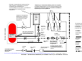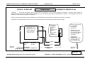
1
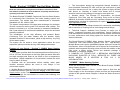
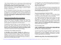
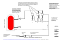
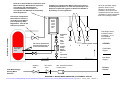
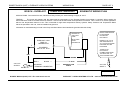
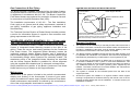
OWNERS MANUAL &
INSTALLATION GUIDE
C2 COMBO with 50 mm ports
Why !
• Reduced Energy Costs
• Reduced Capital Costs
• High System Reliability
• High Performance
Where !
•
•
•
•
Motels / Hotels
Laundrettes
Sports Clubs
Nursing / Aged Hom
and Large Residenc
Hot Water Delivery
• Up to 4365 Litres in the
first hour (50 C temp rise)
ROBERT BOSCH (AUST) PTY. LTD
EVERLAST™ HYDRO SYSTEMS PTY. LTD
57 – 63 MC NAUGHTON ROAD CLAYTON VIC 3168
ABN 41 087 168 116
ACN 087 168 116
14 COMMERICAL DRIVE DANDENONG VIC 3175
Ph 03 9768 2404
Fax 03 9768 2406
PH 03 9541 5555
FAX 03 9541 5595
www.everlastwaterheaters.com
email: [email protected]
www.bosch.com.au
C:\Documents and Settings\Matt\My Documents\Business\everlast\content\commerical_315C250_MANUALandWarranty.doc Page 1 of 12
January, 2006
Revision 3
Read this information in conjunction with Bosch Continuous Flow
Gas Heaters Installation & User Handbook, and pump manufacturers
operating instructions handbook.
•
The Accumulator design has exceptional thermal insulation to
meet Australian Standard AS 1056, and the gas units have no heat
loss when burners are off. As a result, this system is highly efficient
with almost no "standing or waste" heat losses and of course
absolute minimum heat wastage in storage to meet peak use.
The Bosch-Everlast™COMBO Commercial Gas Hot Water System
is a combined Gas Continuous Flow water heating system and
accumulator. The system has been manufactured to Australian
Standards AG 102 and AS 1056.
•
Modular design. The Everlast C2 Accumulator, the Bosch
Continuous Flow units and the Circulating Pump such as Davey
SB30-25 & Grundfos 32-80B; are ALL separate components and are
independently serviced for replacement or repair. No unitary system
high replacement costs.
Bosch - Everlast™COMBO Gas Hot Water System
The system incorporates a full copper heat exchanger for maximum
life and a premium marine grade 316 stainless steel cylinder. The
system is covered by a 10 year warranty in domestic installations,
and 5 year warranty in commercial installations; as per the enclosed
warranty conditions.
The combination of the high efficiency and powerful Bosch
Continuous Flow hot water heaters with the durable, highly
insulated Everlast C2 Accumulator, yields a high delivery, very long
life hot water system.
The system can be sized to meet applications where far more
expensive options would be the only other design alternatives.
Features of your Bosch - Everlast™ COMBO Water Heating
System
• This system provides both flow and temperature buffering from a
250 or 315 litre Accumulator so that high peak hot water draw-offs
and high average peak flows do not result in flow or temperature
fluctuations. (Actual capacities of Accumulators exceed the rated
sizes by about 20 litres).
• Systems with an Accumulator deliver stability under peak
demand extremes without the need to over design a non
accumulator system.
• Multiple Bosch Continuous Flow units may be manifolded to the
Everlast Accumulator with No need for Staging of the Cold Water
Supply Inflow, as the Total flow of the manifolded units has to be
circulated through the Accumulator to ensure best buffering and
recovery performance.
•
50 mm primary flow fittings oriented for commercial manifolding
with a minimum of coupling tees or size change socket fittings.
•
Technical Support. Available from Everlast, to assist you in
design, component selection and specification. Bosch Continuous
Flow manufacturers technical service will provide system information
on units, performance and flueing options for internal units and hot
water accessories.
The Bosch-Everlast™COMBO Water Heating System uses Bosch
Continuous Flow water heaters typically from 132 – 200 MJ/hour.
Multiple Bosch units can be manifolded together with one Everlast C2
Accumulator. When a Single Bosch unit is required an Accumulator is
available with integrated mounting points and with the addition of the
Pipe cover, a space saving, secure and aesthetic package is
presented. As a design example :
A COMPLEX OF TWENTY-FIVE 3 BEDROOM APARTMENTS
INCLUDING ENSUITES IS FULLY SERVICED BY THREE 200
MJ/HR MODEL 25 E HEATERS & TWO 315 L C2
ACCUMULATORS.
" COMBO " Water Heating System
There are three main water "circuits" in the Bosch-Everlast COMBO
Water Heating System :
a) The "Mains Pressure" Circuit - causes water to flow from the
'mains supply' to the Accumulator cylinder and from the Accumulator
cylinder to the system outlets. Diagram 1 shows the "Mains Pressure"
circuit.
C:\Documents and Settings\Matt\My Documents\Business\everlast\content\commerical_315C250_MANUALandWarranty.doc Page 2 of 12
January, 2006
Revision 3
The "Primary Circulation" Circuit - causes water to flow through the gas
heating process. The Primary Circulation Pump sources its water from
the Accumulator cylinder or the mains supply or both.
(This will depend on the flow rate through the mains pressure circuit).
Because heated water is always discharged to the Accumulator the
delivered temperature is very stable. Diagram 2 shows the Mains
Pressure + Primary circuits.
b) The "Secondary Circulation" Circuit (this is only required where
there is a need for secondary pipework reticulation i.e. hot water flow
is maintained in a loop through all outlets). In these installations the
secondary return is connected to the hot water primary flow pipe to
ensure the hot water that is circulating does not short circuit the mix
into heated water. Diagram 3 shows the Mains Pressure + Primary +
Secondary circuits.
Notes for the following Water flow circuit diagrams :
Applications
In applications where hot water supply is direct and non-recirculated,
such as some motels, laundrettes, hospitals and sports club
showers; the mains pressure and primary circuits provide a simple
system capable of very high delivery and heat transfer.
In applications where hot water is to be circulated past the outlets,
such as some motels, apartments and very large homes; the
secondary circulating pump and circuit provides immediate hot water
delivery at each outlet with this minor addition to the system. Usually
made in-situ, this circuit is additional to the Integrated Package and is
not provided in the Bosch-Everlast Integrated Package.
Tempering or Thermostatic mixing valves
In accordance with Australian Standard AS 3500.4, it is
recommended that where required a temperature control device or
mixing valve be fitted between the water heater and bathrooms and
ensuites to reduce the risk of scalding. This is achieved by
controlling water temperature to below 50 degrees C. The locations
as shown on the Water flow circuit diagrams are where required at
point of use in the mains pressure circuit.
To ensure there is no conflict with thermostat set temperature of
the COMBO system, they are not associated with the primary or
secondary circulation circuits.
Expansion Relief Valve.
A 750 – 850 kPa expansion relief valve is recommended in the
Primary Circulation Circuit which is transferring heated water into
the Accumulator. The valve allows for expansion of water in the
primary piping loop during the heating cycle. Discharge may
occur during heating and is normal.
Pressure and temperature relief valve (PTR)
A Pressure Relief Valve is located on the Hot Water Outlet
connection of each Bosch Heater Unit in accordance with AG
102, to prevent pressure damage to the heat exchanger.
The COMBO Accumulator cylinder features dual 20 mm PTR
ports. Two 850 kPa PTR valves are provided to meet
requirements in accordance with AG 102 Sec 2.7.10. State
Regulations may require the installation of two PTR valves and/or
PTR valves in the piping manifold configuration. If only one PTR
valve is required, the second provides safe redundancy or a
blanking plug may be substituted. The PTR valve pressure
setting should always be 850 kPa.
Pressure limiting valve
A 500 - 600 kPa Pressure Limiting valve must be fitted, to
ensure correct function of the system in conjunction with
the PTR valve / Expansion Relief valve.
As shown in the Water Flow Circuit Diagrams, isolating valves for
ease of service, line strainers and non return valves are
recommended as good installation practice and to ensure
protection of pumps from contamination or damage in the event
of water system pick up of contaminants.
Installation must comply with Australian Standard AS 3500.4 National Plumbing Code, and any local authority regulations.
C:\Documents and Settings\Matt\My Documents\Business\everlast\content\commerical_315C250_MANUALandWarranty.doc Page 3 of 12
January, 2006
Revision 3
Tempering or Thermostatic Mixing valves as required
for Safety Temperatures in areas used primarily for the
purposes of personal hygiene as defined in AS3500 or
by Industry or local regulations
All hot & cold water supply
pipework shown in this
diagram to be sized and
installed in accordance with
AS3500 and local and
industry regulations to
ensure adequate flow to the
buildings outlets.
Pressure & Temperature
Relief Valve or Valves in
accordance with AG102
& as required by State
Regulations. Two 20 mm
PTR Ports provided
Everlast C 2 Accumulator
This design shows
3 building outlets
numbered 1, 2 & 3
for illustrative
purposes only
1
2
3
LEGEND :
Cold Water
Supply
Non return
valve
500 - 600 kPa Pressure
Limiting valve
Hot Water
Supply :
Cold Water Supply
Usually Mains
Pressure.
DIAGRAM 1. WATER MAINS PRESSURE CIRCUIT
C:\Documents and Settings\Matt\My Documents\Business\everlast\content\commerical_315C250_MANUALandWarranty.doc Page 4 of 12
January, 2006
Revision 3
External or Internal Bosch Continuous Flow
Water Heater(s). Manifolded if required in
accordance with manufacturers
recommendations. PTR valves in
accordance with AG102 & as required by
State Regulations.
Tempering or Thermostatic Mixing valves as required
for Safety Temperatures in areas used primarily for the
purposes of personal hygiene as defined in AS3500 or
by Industry or local regulations
Pressure & Temperature
Relief Valve or Valves in
accordance with AG102
& as required by State
Regulations. Two 20 mm
PTR Ports provided
All hot & cold water supply
pipework shown in this
diagram to be sized and
installed in accordance with
AS3500 and local and industry
regulations to ensure adequate
flow to the buildings outlets.
Bosch
Model
17E or
21E or
25E or
32E
This design shows
3 building outlets
numbered 1, 2 & 3
for illustrative
purposes only
Everlast C2 Accumulator
Expansion
relief
Valve
Thermostat
set to 60 –
70 C
240 V at C2 Accumulator
Provides pump power &
control via Thermostat.
Isol. valve
Non
return
Valve
Primary
Pump.
Davey
SB30-25
or
equivalent
LEGEND :
1
2
3
Cold Water
Supply
Isol. valve
Isolating
valve
Non return
valve
Hot Water
Supply :
500 - 600 kPa Pressure
Limiting valve
Primary
Circuit :
Cold Water Supply
Usually Mains
Pressure.
DIAGRAM 2. WATER MAINS PRESSURE plus PRIMARY CIRCUIT
C:\Documents and Settings\Matt\My Documents\Business\everlast\content\commerical_315C250_MANUALandWarranty.doc Page 5 of 12
January, 2006
Revision 3
External or Internal Bosch Continuous Flow
Water Heater(s). Manifolded if required in
accordance with manufacturers
recommendations. PTR valves in accordance
with AG102 & as required by State
Regulations.
Tempering or Thermostatic Mixing valves as required
for Safety Temperatures in areas used primarily for the
purposes of personal hygiene as defined in AS3500 or
by Industry or local regulations
Pressure & Temperature
Relief Valve or Valves in
accordance with AG102
& as required by State
Regulations
Bosch
Model
17E or
21E or
25E or
32E
This design shows
3 building outlets
numbered 1, 2 & 3
for illustrative
purposes only
Everlast C2 Accumulator
Expansion
relief Valve
Non return
Valve
Thermostat
set to 60 –
70 C
240 V at C2 Accumulator
Provides pump power &
control via Thermostat.
Isol. valve
1
Primary
Pump.
Davey
SB30-25 or
equivalent
2
3
LEGEND :
Cold Water
Supply
60 Mesh
line strainer
Hot Water
Supply :
Isol. valve
Non return
Valve
Isolating
valve
Non return
valve
500 kPa Pressure
Limiting valve
Secondary Pump
Davey SB25-20,
Grundfos 25-40B
or equivalent
Isol. valve
Primary
Circuit :
Secondary pipework suitable
for drinking water purposes.
Constant thermal circulation as
required.
Cold Water Supply
Usually Mains
Pressure.
C:\Documents and Settings\Matt\My Documents\Business\everlast\content\commerical_315C250_MANUALandWarranty.doc Page 6 of 12
January, 2006
Revision 3
DIAGRAM 3. WATER MAINS PRESSURE plus PRIMARY CIRCUIT plus SECONDARY CIRCUITS
Secondary
Circuit :
COMBO System Capability
The following chart will assist in the selection of the COMBO
System that meets with your specific requirements.
Even if you have specified a basic COMBO System with a single
Bosch Continuous Flow Water Heater and the Everlast Accumulator
and then your hot water delivery requirements increase; or if the hot
water demand is not immediately known; this is a System where, if
required, a further Bosch Continuous Flow Water Heater may be
added.
HOT WATER DELIVERY CHART
COMBO with Bosch 17E, 21E or 25E Gas Heater Units & one
Everlast 315 Litre C2 Figures based on heating from 15 °C up to 65 °C
(fairly typical)
COMBO Heat up
Unit Model Time
(mins)
First hour
delivery
(Litres)
Further
hourly
delivery
(Litres/hr)
Typical Number of
motel/hotel rooms assuming
2 persons per room
showering. **
3 STAR
5 STAR
ACCOM
ACCOM.
315117E
36
849
534
14
9
315121E
29
963
648
16
11
315125E
24
1125
810
19
13
COMBO with Bosch 17E, 21E or 25E Gas Heater Units & one
Everlast 250 Litre C2
Figures based on heating from 15 °C up to 65 °C (fairly typical)
COMBO Heat up
Unit Model Time
Burner Size
(MJ / hour)
(mins)
Tank
Capacity
(Litres)
First hour
delivery
(Litres)
[ Reference: Robert Bosch (Australia) Pty Ltd ]
Further hourly
delivery
(Litres/hr)
COMBO Pipe and Fittings Sizing Guidelines
250117E
36
132
250
784
534
The Bosch-Everlast™COMBO Gas Hot Water System relies on the
Everlast Accumulator which will accommodate from one to 5 Bosch
Continuous Flow Water Heaters.
250121E
29
160
250
898
648
Specified in conjunction with the Grundfos UPS 32-80 B pump, a
system may be assembled with consistent pipe and fittings sizing.
250125E
24
200
250
1060
810
** Notes for tables: Motel rooms will be a mixture of 1 bedrooms
with 1 or 2 people showering (business accom. is typically 1 person);
and 2 bedrooms with 2 or 3 persons showering. Therefore to average
at 2 persons per room is conservative, safe design.
These are scenarios ranging from small motel/hotel/unit
developments up to significant multi room accommodation; serviced
with very efficient hot water plant .
3 Star Accommodation equals 30 Litres per person per Peak Hour
5 Star Accommodation equals 45 Litres per person per Peak Hour
The 50 mm sizing of Primary Circulation piping in the COMBO
design, ensures that the system will meet the range of major
commercial applications of single or multiple Gas units; manifolded to
the COMBO. Connection may be made using 50 mm direct coupling
as required. The factors to be considered by the Installer are the
mains supply piping/flow rates, and Secondary Circuit piping, if
required.
The following design principles should be considered in the
determination of the mains and secondary piping sizes :
If pipework is undersized for the required flow (litres/sec) or
(litres/min), then the velocity will increase (metres/sec) resulting in an
increased pressure loss. If pipework is oversized for the required
flow, then the heat loss will be increased.
C:\Documents and Settings\Matt\My Documents\Business\everlast\content\commerical_315C250_MANUALandWarranty.doc Page 7 of 12
January, 2006
Revision 3
The Bosch Continuous Flow Water Heater Manuals available from
Robert Bosch Australia; and the publication "Selection and Sizing of
Copper tubes for water piping Systems" by B. Smith, available from
Copper & Brass Information Centre, or Institute of Plumbing Australia;
are helpful publications.
Whilst major systems do require the input of competent hot water
system designers, the application of the Guidelines in the above
publications and particularly the Guidelines for Installation in the
Bosch Continuous Flow Water Heater Manuals will facilitate good
design in respect to Pipework.
COMBO System Pump, Flow & Pressure characteristics.
Primary Circulation Circuit. Typical for the 160MJ units.
No of
160 MJ
units
Assumed Pressure
Flow Rate Loss
Litres per kPa
min
1
10-20
30-40
2
20
34
3
30
38
4
40
42
5
50
46
Typical Pump
Model &
Speed Setting
DaveySB30-25
Speeds 1 & 2
Basis of the Pressure &
Flows in Primary Pipe
Sizing and approximate
lengths.
25 mm pre-fitted Integrated
Package.
Gfs UPS32-80B 32 mm tube up to a length
Speed 2
of 20 metres & 20 mm tube
at Gas Units up to 3 metres,
Gfs UPS32-80B yields very small pressure
Speed 2
drops. Greater lengths may
Gfs UPS32-80B be calculated.
Speed 2
Gfs UPS32-80B
Speed 2
These Davey & Grundfos pumps are multi speed pumps where pump speed
may be matched to system design (see above). They have a bronze body
and brass connections. Refer to the Davey & Grundfos Pump Manuals for
single speed and Secondary Piping Circulator pump alternatives.
Internal Installation Water Safety
For internal (indoor) installations of Accumulator, a safe tray is
recommended in accordance with Australian Standard AS 3500.4
This is necessary to prevent damage associated with a leaking pump
or fittings, or when flushing the Accumulator.
Secondary Circulating Pump and Pipework
The secondary circulating pump and pipework (where required) will
always be sized to produce the flow rate that has been determined
from system heat losses and draw off's that provides acceptable
temperature drop before return.
The Davey SB30-25 multi speed pump may be utilised for secondary
circulation, or when secondary pipework is 25 mm or 18 mm, the
SB25-20 or Grundfos equivalent may be preferable such as the UPS
25-40B, UPS 25-60B & UP 25-80B. Flow characteristics to suit the
system may be selected from the manufacturers Circulator Pumps
Handbooks. These handbooks incorporate flow curves for each pump
which may be relied upon to suit the hot water circulation
requirements of the system.
Electrical Connection & Wiring
The Bosch-Everlast™COMBO Commercial Gas Hot Water System is
designed for single phase 240 V. A.C. supply only. Australian
Standard AS 3000 – (Wiring Code), and local supply authority
regulations apply.
Notes for the following Schematic Wiring Plans :
240 V AC Supply is required at the point of connection of the
Accumulator Thermostat for the operation of the Primary Circulating
Pump. Where a Secondary Circulating Pump is required, the AC
supply to this pump must be located in close proximity to the pump.
Connection is made at the terminal location points under the IP rated
weatherproof thermostat cover. Wiring entry to the connection point is
made through the blanked-off standard conduit port adjacent to the
thermostat cover, by removal of the blanking plug. Always install a
standard 20 mm conduit elbow to the port to ensure conduit support.
240 V AC Supply may be required at the point of connection of the
Gas Continuous Flow Water Heater(s) to energise the electronic
burner ignition system.
High Temperature Hot Water Applications are referred to the further
schematic for the high temperature thermostat, and the notes therein.
C:\Documents and Settings\Matt\My Documents\Business\everlast\content\commerical_315C250_MANUALandWarranty.doc Page 8 of 12
January, 2006
Revision 3
ROBERT BOSCH (AUST) - EVERLAST HYDRO SYSTEMS
WIRING PLAN
BOSCH - EVERLAST
PAGE 1 OF 2
SCHEMATIC WIRING PLAN
COMBO MODEL
TESTING :
The pump will operate until the thermostat set temperature of the Everlast Storage Accumulator is reached. When testing the
thermostat there will be a CLOSED CIRCUIT between L4 and T2 until the thermostat set temperature is reached. There should be 240 V AC
between L1 and L3 when the system is energised.
Refer to Gas Unit manufacturers recommendations for multiple heater units and when secondary return pumping is required.
Information on troubleshooting is found in the Pump and Gas Heater User Handbooks (provided with this Guide).
L1
L3
EVERLAST C2
THERMOSTAT OF
BLACK
L4
RED
EWT1 SERIES
SET AT 65 C
BOSCH CONTINUOUS
FLOW WATER
HEATER OR
MULTIPLES.
GRUNDFOS
or DAVEY
UPS TYPE
PUMP.
Typical: Davey
SB30-25
L
N
WITH PUMP
SHAFT
HORIZONTAL
T2
E
MODELS 17E, 21E &
25E REQUIRE 240 V
AC. FOR ELECTRONIC
IGNITION. MAY BE
PROVIDED
THERE IS NO
ELECTRICAL
CONNECTION FROM
THE GAS UNIT TO
CIRCULATING PUMP
BROWN
240 V AC
SUPPLY
ACTIVE
NEUTRAL
RED
BLACK
GD MAINS
TERMINAL CONNECTOR
BLUE
GREEN/YELLOW
EARTH
240 V AC
SUPPLY
PAGE REV :
ROBERT BOSCH (AUST) PTY LTD www.bosch.com.au
2
EVERLAST™ HYDRO SYSTEMS PTY LTD. www.everlastwaterheaters.com
ROBERT BOSCH (AUST) - EVERLAST HYDRO SYSTEMS
BOSCH – EVERLAST
WIRING PLAN
COMBO HIGH TEMP MODEL
PAGE 2 OF 2
SCHEMATIC WIRING PLAN
APPLICATIONS : Commercial Process, Industrial or Dairy Industry etc. water heating to supply at 90 ºC.
TESTING :
The pump will operate until the thermostat set temperature of the Everlast Storage Accumulator is reached. When testing the
thermostat there will be a CLOSED CIRCUIT between 1 and 2 until the thermostat set temperature is reached. This is a 240 V AC series application
without over temperature thermal cut out. This is intended for high water temperature delivery systems. Safety Pressure and Temperature Relief
Valves as specified in AG 102, must be installed into pipework.
Information on troubleshooting is found in the Pump and Gas Heater User Handbooks (provided with this Guide).
GRUNDFOS
UPS TYPE
PUMP
WITH PUMP
SHAFT
HORIZONTAL
EVERLAST HIGH
TEMP C2
THERMOSTAT
1
2
EW SERIES
SET UP TO 90 ºC
BOSCH CONTINUOUS
FLOW WATER
HEATER OR
MULTIPLES.
MODELS 17E, 21E &
25E REQUIRE 240 V
AC. FOR ELECTRONIC
IGNITION. MAY BE
PROVIDED
THERE IS NO
ELECTRICAL
CONNECTION FROM
THE GAS UNIT TO
CIRCULATING PUMP
RED
BROWN
240 V AC
SUPPLY
ACTIVE
NEUTRAL
RED +
BLACK —
GD MAINS
TERMINAL CONNECTOR
BLUE
GREEN/YELLOW
EARTH
240 V AC
SUPPLY
PAGE REV :
ROBERT BOSCH (AUST) PTY LTD www.bosch.com.au
1
EVERLAST™ HYDRO SYSTEMS PTY LTD. www.everlastwaterheaters.com
HEATER SUPPORT BRACKET MOUNTING DETAIL :
Gas Connections & Gas Piping
The Bosch-Everlast™COMBO Commercial Gas Hot Water System
incorporates Bosch Continuous Flow Water Heaters which are Type
A Appliances in accordance with AG 102. The Bosch Continuous
Flow Water Heaters are produced for connection to Natural Gas and
for connection to Liquified Petroleum Gas (LPG).
C2 Accumulator
Outer case
Integrated
Heater
Mounting
inside case
The Installation requirements of AG 601 - The Gas Installation
Code, apply to all general work & safety requirements, materials &
gas piping, installation of gas piping, appliance installation and
commissioning.
Case
Mount Bracket
Supplied fitted stud & dome nut, at each mount
point ensures positive clamping between the
Integrated Heater Mounting & Heater Support Bracket.
Refer to the Warranty Conditions & Exclusions.
INTEGRATED HEATER MOUNTING ( C2 – 32 mm units
only ) This feature is not available on 50 mm outlet units
Maintenance of the system is limited to the periodic recommended
draining and flushing of the Accumulator in areas of poor water
quality and sediment in water supply. Bosch Continuous Flow Water
Heater maintenance requirements as outlined by the manufacturer
of the Gas unit(s) adopted, should also be complied.
Dome Nut / Stud
Warranty Conditions
1.
The system must be installed by a licensed plumber and/or electrician in
accordance with Bosch Continuous Flow Water Heater manufacturers &
Everlast™ installation instructions; and all relevant statutory and local
requirements of the State in which the system is installed.
2.
The Bosch-Everlast™COMBO Commercial Gas Hot Water System must
be operated and maintained in accordance with instructions supplied by
Robert Bosch (Australia) Pty Ltd & Everlast™ Hydro Systems Pty Ltd
3.
The Accumulator is warranted to be defect free for a period of 10 years
in domestic installations, and 5 years in commercial installations. This
warranty only applies to the Accumulator product and does not apply to
any additional electrical, gas and/or plumbing parts supplied by the
installer. The Bosch Continuous Flow Water Heaters are warranted as
detailed in the manufacturers handbook.
4.
The system is covered for the indicated period from the date of the
original purchase.
5.
Should this system be installed in a regional location where regular
flushing is required due to sediment build-up, then a drain cock or tee for
flushing must be fitted at the time of installation. If in doubt consult your
Installation Contractor.
Simply determine the position of the Bosch Continuous Flow Water
Heater and mount your Heater on the Support Bracket.
Maintenance
Bosch Continuous Flow
Heater
Enlarged mount
detail.
The Technical Services Division of Robert Bosch Australia provides
a service for Information Support in regard to Gas connection and
piping requirements to the Gas units.
A feature of the Bosch-Everlast™COMBO Commercial Gas Hot Water
System is Integrated Heater Mounting located on the side of the
casing. These are secure, load bearing positions for the Continuous
Flow Water Heater. The Integrated Heater Mounting locates the
(optionally supplied) Heater Support Bracket, and is designed to
ensure stable support of the Heater and pipe mounted primary pump
for freestanding design where Systems are externally located. The
attachment points of the Integrated Heater Mounting are stud-fitted
and the Heater Support Bracket is predrilled for correct alignment
using the supplied dome headed nuts. A schematic is shown below.
Heater Support Bracket
C:\Documents and Settings\Matt\My Documents\Business\everlast\content\commerical_315C250_MANUALandWarranty.doc Page 11 of 12
January, 2006 Revision 3
6.
Where the heater is installed outside the boundaries of a Capital Cities
Metropolitan area i.e. those areas on STD, the cost of transport, insurance
and travelling between the nearest Everlast™ accredited Service Agent’s
premises will be charged to the owner.
Warranty Exclusions
The following warranty exclusions may cause the system warranty to become
void. This may incur a service charge and cost for parts should they be
necessary.
1.
Where service is required to reconnect the water heater operation due to
problems related with abnormal water supply (i.e. high water pressure),
faulty plumbing, gas connection and/or electrical wiring, or major
variations in electrical energy supply.
2.
Where a pressure limiting valve as shown in the water circuit diagrams,
has not been fitted during installation.
3.
Where the system fails due to misuse, accidental damage, acts of God,
incorrect installation or unlicensed service repair work attempts.
4.
Where system service is required due to the non-conformance with this
warranty’s recommended maintenance in certain water quality conditions
(refer warranty condition 5).
5.
Claims for damage to walls, foundations (outside), furnishings (inside),
roofs or other losses, directly or indirectly due to leakage from the
COMBO Gas water heater/accumulator system.
6.
Damage or breakage is not covered by this warranty, and should be
added separately to your general household insurance policy.
7.
This warranty does not cover the effects of sludge/sediment, or mineral
salts as a result of connection to a water supply from unfiltered sources
i.e. spring, dam, bore, river or other unreticulated supply.
8.
Where water stored in the cylinder exceeds the following levels : Total dissolved solids
Electrical Conductivity
Total hardness
Chloride
Magnesium
Sodium
pH
600 mg/litre or p.p.m.
850 uS/cm.
200 mg/litre or p.p.m.
250 mg/litre or p.p.m.
10 mg/litre or p.p.m.
150 mg/litre or p.p.m.
Min 6.5 and Max 8.5
9.
The benefits conferred by this warranty are in addition to all other
rights and remedies in respect of the product, which the purchaser
has under the Trade Practices Act (Commonwealth) 1975, and
similar State or Territory Laws.
10.
Where the Support Bracket connection to the Integrated Mounting
Points is incorrectly installed or the Heater and/or bracket is mounted
directly onto the outer casing and not at the Integrated Mounting
Points.
11.
Where PTR valves are not installed in the hot water outlets(s) from
the heater(s) in accordance with AG 102.
Component Warranty Cover*
Free replacement of faulty
Components or, where applicable,
Free replacement of water heater
Including labour
Accumulator Warranty Cover*
Should the COMBO stainless steel
Accumulator rupture, a new
unit will be supplied free
Of charge. Total installation costs
will be a cost to the owner.
Single Domestic
Application
Single/Multi
Commercial
Application
One year
Single Domestic
Application
One year
Single/Multi
Commercial
Application
Year One to year
Ten Inclusive
Year One to
year Five
Inclusive
* Where the heater is installed outside the boundaries of a Capital Cities Metropolitan
area i.e. those areas on STD, the cost of transport, insurance and travelling between
the nearest Everlast™ accredited Service Agent’s premises will be charged to the
owner.
Further Information :
EVERLAST™ HYDRO SYSTEMS PTY. LTD.
14 COMMERICAL DRIVE DANDENONG VIC 3175
Ph: (03) 9768 2404 Fax: (03) 9768 2406
www.everlastwaterheaters.com
ROBERT BOSCH (AUST) PTY. LTD
57 – 63 MC NAUGHTON ROAD CLAYTON VIC 3168
Ph: (03) 9541 5555
Fax: 03 9541 5595
www.bosch.com.au
C:\Documents and Settings\Matt\My Documents\Business\everlast\content\commerical_315C250_MANUALandWarranty.doc Page 12 of 12
Good . Better . Bosch
January, 2006 Revision 3