1
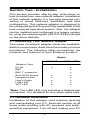
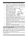
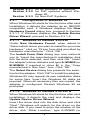
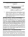
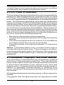
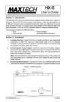
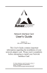
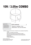
High Performance
Plug and Play
16-bit Ethernet
Adapter
NXP-16
USER'S GUIDE
Part #MAN107 Rev. 1.0
NX16BT/D
Contents
Section One - Introduction ......................... 1
Section Two - Installation ........................... 2
Section Three - Driver Installation .............. 8
Section Four - Troubleshooting .................. 8
Section Five - Cable Information ............. 10
Section Six - Specifications ..................... 10
Section Seven - Technical Support .......... 11
Section Eight - Notices ............................. 12
Section One - Introduction
Maxtech network adapters are high performance,
Industry Standard Achitecture (ISA) Ethernet network adapters designed for Plug and Play (PnP)
systems. The adapters are NE-2000 compatible
and include a 16KB RAM buffer for improved network transmission and reception.
Plug and Play is a set of specifications that define
the ability for the computer hardware or operating
system to automatically configure all devices that
are installed, relieving the user of the need to
determine which addresses and interrupts to use
for each device.
For non-PNP (legacy) systems, a setup program
(SETUP.EXE) is provided to configure the cards for
use in any IBM PC/XT/AT or fully-compatible computer.
The minimum hardware requirement is an IBM PC/
XT or fully-compatible PC with 512K RAM running
DOS 6.2 or higher. The network operating system
you use may have higher requirements.
1
Section Two - Installation
This section provides step-by-step instructions on
how to install your new network adapter. Installation
of this network adapter is a two-step process consisting of actual hardware installation and card
configuration. This network adapter is designed to
be configured by the Plug and Play capabilities of the
host computer/operating system. Also, the adapter
can be installed and configured in a legacy system
by using the setup program (SETUP.EXE) included
on the driver diskette.
2.1 Unpacking Your Network Adapter
Two types of network adapter cards are available.
Before you proceed, determine the model you have
purchased. The following table summarizes the
contents and features of your Ethernet product:
Model
NXP-16T
x
x
Adapter Card
RJ-45
BNC
BNC T-connector
Boot ROM Socket
Installation disk
User's Guide
LINK LED*
ACT LED
x
x
x
x
x
NXP-16BT
x
x
x
x
x
x
x
x
x
*Note: The LINK LED only indicates a twisted-pair
connection. It is disabled for any other cable type.
2.2 Hardware Installation
Installation of this adapter card requires opening
and manipulating your PC. Exercise caution at all
times when working with AC powered and staticsensitive equipment. Turn off and unplug your PC
2
before installation. Discharge any static electricity
from your body by touching any metal surface.
1.
2.
3.
4.
5.
6.
7.
8.
9.
Turn off your computer and all peripherals.
Make a note of the power cord and other
cables connected to your computer and
disconnect them.
Remove your computer’s cover (refer to
your computer’s owner manual).
Select any available
Figure 1
expansion slot, and
then remove the slot
cover (refer to Figure
1). A 16-bit expansion
slot is recommended.
Touch the computer
chassis before removing the adapter from
its anti-static bag. This will discharge any
static electricity from your body.
Carefully install the adapter by firmly pressing the card into the slot you have chosen,
applying even pressure until the adapter is
completely seated in the slot.
Fasten the retaining bracket with the screw
from the slot cover. Make sure the adapter
is properly aligned. Store the slot cover for
future use.
Replace the computer cover and reconnect
the power cord and all cables.
Attach the network cable to your adapter.
2.3 Card Configuration
Plug and Play systems determine the network
card's configuration during boot up. Non-PnP systems require the use of the setup program,
SETUP.EXE, included on the driver diskette in the
root directory to configure the card.
Proceed to the section which matches your system
configuration:
3
Section 2.3.1 for all Windows 95 systems
Section 2.3.2 for PnP systems without Windows 95
Section 2.3.3 for Non-PnP Systems
2.3.1
Configuration in Windows 95
When Windows 95 starts for the first time after card
installation, it detects the adapter as an NE2000
compatible card. If Windows displays the New
Hardware Found dialog box, proceed to Section
2.3.1.1. If Windows displays the Update Device
Driver Wizard, proceed to Section 2.3.1.2.
2.3.1.1 Windows 95 Release 4.00.950
Under New Hardware Found, when asked to
“Select which driver you want to install for your new
hardware,” click on “Driver from disk provided by
hardware manufacturer.” Click “OK.”
The Install From Disk dialog box now instructs
you to “Insert the manufacturer's installation disk
into the drive selected, and then click OK.” Insert
the adapter's driver diskette and type A:\WIN95 (or
B:\WIN95 if inserted in drive B) in the “Copy
manufacturer's files from:” box. Click “OK.”
The Select Device dialog box presents the selection for the adapter. Click “OK” to install the adapter.
Windows 95 may request its own installation disks
for some files. Insert the Windows 95 disks as
required. When all necessary files are copied, the
adapter is configured. Restart Windows 95 as
prompted.
2.3.1.2 Windows 95 Release 4.00.950 B
When Windows 95 starts for the first time after card
installation, it detects the card and displays the
Update Device Driver Wizard.
Insert the driver disk into the disk drive and click
“Next.” Windows will search for the driver on the
driver disk. If you need to enter the location of the
driver, click “Other Location,” type A:\WIN95 (or
4
B:\WIN95) in the entry box and click “OK”. Click
“Finish.”
Windows 95 may request its own installation disks
or CD for some files. Insert the Windows 95 disks
or CD as required. When all necessary files are
copied, the adapter is configured. Restart Windows 95 as prompted.
2.3.2 Configuration in PnP Systems without
Windows 95
If the card is installed in a PnP system without
Windows 95, the system assigns the card an I/O
Base Address and IRQ. Run SETUP.EXE in the
root directory of the driver diskette and use the
View Current Configuration option to confirm the
adapter's configuration. If you wish to change the
card configuration from the one assigned, select
Setup, change the Operating Mode to Jumperless
and configure the adapter as outlined in Section
2.3.3 for legacy systems. Continue to Section 2.4
to run adapter diagnostics to ensure correct installation.
2.3.3 Configuration in Legacy Systems
When using the card on a legacy (non-PnP) system, the setup and diagnostic program SETUP.EXE
is used to configure the adapter.
Note: To use the network card in a legacy system,
the Operating Mode must be set to Jumperless
instead of Plug and Play
To run the setup program, insert the driver diskette
into drive A: (or B:).
1.
2.
3.
4.
5.
At the DOS prompt type A:\SETUP
Select Setup
Change the Operating Mode to Jumperless.
Configure the I/O Base Address and Interrupt to the desired settings for your system.
Press Esc to update the adapter.
5
For more information on running SETUP, refer to
the file README.TXT in the root directory of the
driver diskette.
The following configuration options are available in
the SETUP Main Menu:
•
•
•
View Current Configuration
Setup
Run Diagnostics
View Current Configuration displays the current
settings of the card.
The Setup option allows user selection of parameters such as Operating Mode, Medium type, FullDuplex Enable/Disable, I/O Base Address, Interrupt, and Boot ROM Address. Setup is used to
configure the card in systems without Plug and
Play capabilities.
2.4 Testing The Adapter
Adapter diagnostics are included in the SETUP.EXE
program found in the root directory of the driver
diskette. Refer to the file README.TXT in the
same directory for detailed information.
Note: To run the diagnostics under Windows 95,
click on Start/Shut down and select “Restart the
computer in MS-DOS mode.” Run SETUP.EXE
from the DOS prompt.
Setup provides the following testing options when
you select Run Diagnostics from its Main Menu.
• Run EEPROM Test
• Run Diagnostics on Board
• Run Diagnostics on Network
The EEPROM Test option performs read/write
tests on the adapter's on-board EEPROM registers
and reports the results.
The Run Diagnostics on Board option runs several tests and the results are indicated by either
PASS or FAIL counts. Make sure that the network
6
cable is attached (and properly terminated if using
a BNC connection) to the adapter when using this
option. If any test has a fail count, press the
spacebar for help on the reason for the failure and
possible solutions
The following tests are performed in the Run
Diagnostics on Board option:
1.
2.
3.
4.
5.
Configuration Test: Checks the initial status of the Ethernet controller
I/O Test: Check I/O accessibility
Internal Loop back Test: Checks adapter's
controller.
External Loop back Test: Performs transmit/receive tests on the network link
RAM Test: Checks on-board RAM
The Run Diagnostics on Network option allows
the user to test the network cable connection
between two cards. One card is setup as a Responder and a second card is setup as an Initiator. The Initiator and Responder will exchange
packets and display the number of transmit and
receive packets that have passed or failed. Note:
A Responder can only recognize one Initiator at a
time.
2.5 Boot ROM Installation (optional)
An empty ROM socket is provided on the adapter
to accept an optional Remote Boot ROM (available
from your dealer). The Boot ROM allows the PC to
load the Operating System over the network for
diskless applications.
1.
2.
Insert the Boot ROM into the socket. Make
sure that the notch on the ROM matches the
one on the socket (refer to Figure 2).
Configure the adapter using the SETUP
program to enable the Boot ROM function
by selecting the appropriate address from
the Boot ROM Base Address option. Refer
to Section 2.3 for more information on run7
ning the SETUP program.
Figure 2
Align ROM
and socket
notches
3.
Follow the Remote Boot Workstation installation procedure given in your network operating system manual (i.e. create a Boot
Image on the server for Novell networks, or
start remote booting services on LAN Manager networks, etc.).
Section Three - Driver Installation
The network operating system (i.e. Novell, Windows NT, LAN Manager, etc.) that you are using
requires a driver to access the network adapter
card. The network adapters are NE-2000 compatible and can use the NE-2000 driver supplied
with your network operating system. Drivers for
most popular network operating systems are included on the driver diskette in separate
subdirectories. These drivers can be copied to your
hard-drive by using the INSTALL.EXE program on
the driver disk. Information on using each driver is
available by running HELP.EXE from the root
directory of the driver disk.
Section Four - Troubleshooting
This section describes some of the common problems you may encounter while using your network
adapter. When troubleshooting, you should make
sure that the network you are connected to is
8
functioning. If you suspect that the adapter is
malfunctioning, replace it with another adapter
which is known to function properly. Also try the
adapter in another computer. This can determine
whether the adapter or computer causes the problem. If you cannot resolve your difficulty after
reading the following information, contact your
dealer or vendor for assistance.
Most adapter failure after installation is caused by
A) I/O base address and IRQ Line conflict, or B)
Cable problems.
4.1 I/O Base Address and IRQ Conflict
Make sure that the I/O address and IRQ used by
the adapter is not already in use by another
device in your PC. If your PC has built-in serial
ports then you will not be able to use IRQ 4
(COM1) or IRQ 3 (COM2). Other adapters in your
system may already use addresses 0300H or
0320H (example: sound/audio card). Vary the
settings on your network adapter by running SETUP
again to eliminate the conflict. Running the diagnostics in SETUP will also help to detect configuration conflicts.
4.2 Cable Problems
A) Observe the green Link Status LED if you are
using a 10Base-T network. Turn on the computer.
Connect the network cable and observe the green
LINK LED. If the LED is ON, then the system is
connected. Otherwise check for a proper RJ-45
connection.
B) Make sure the coaxial cable is properly terminated if you are using a 10Base-2 network. Each
end of a coaxial segment must be properly terminated with a 50-ohm terminator. You may use a
simple ohm meter to determine if the cable is
functioning properly. Disconnect all nodes on the
network and measure the resistance of the termi9
nators. If the terminators do not measure 50 ohms
+/- 1%, replace the terminator. Measure the coaxial
cable with a 50-ohm terminator attached to one
end. The total resistance of the cable plus the
terminator should be no more than a few ohms
more than the terminator alone.
Section Five - Cable Information
The network adapters support both popular cable
schemes used in Ethernet networks: 10Base-T
and 10Base-2. The following are the recommended
specifications for proper network cabling.
10Base-T networks use unshielded twisted-pair
cable and 8-pin RJ-45 modular connectors. Use
only 22-26 AWG 2- or 4-pair 100 ohm/ft UTP
(Catagory 3) or better cable. The cable must use
solid copper conductors and UL codes CM, CMR,
and CMP are required. The computer on the network is connected via a star topology (i.e. each
node is connected to a HUB, not to each other).
Maximum cable length is 300' (100 m).
10Base-2 networks use a single conductor coaxial
cable and BNC connectors. Use only RG-58A/U or
RG-58C/U coaxial cables. Each network node is
connected to the coaxial cable via a T-connector
(included). The minimum distance between Tconnectors is 1.6' (0.5m). The T-connector must be
plugged directly into the network adapter (no cable
is allowed between the T-connector and the
adapter). No more than 30 connections are allowed per segment and the maximum segment
length is 607' (185 m). The cable must be terminated at each end by one 50-ohm terminator.
Section Six - Specifications
Network Standard:
IEEE 802.3
Computer Interface:
ISA bus 8 or 16 bit, auto detect
Hardware Compability: NE2000
10
I/O address:
200, 220, 240, 260, 280, 2A0, 2C0,
2E0, 300, 320, 340, 360, 380, 3A0,
3C0, 3E0
IRQ line:
2 (9), 3, 4, 5, 10, 11, 12, 15
RAM buffer:
16 KB
Boot ROM address:
C000, C400, C800, CC00, D000,
D400, D800, DC00
Power Consumption: 2.5 W
Temperature:
0 to 55 degrees C (Operating)
Humidity:
10% to 90% (Non condensing)
Dimensions:
6.39" x 2.48"
Certification:
FCC Part 15 Class B
Drivers:
Novell NetWare 3.x, 4.x, NetWare LAN
WorkPlace TCP/IP, Novell LAN Analyzer for NetWare,
Novell Personal Netware, Wollongong Pathway Access,
FTP PC/TCP, NCSA TCP/IP, Microsoft LAN Manager,
Microsoft Windows For Workgroups, Microsoft Windows
NT, Microsoft Windows 95, IBM LAN Server, IBM LAN
Support, IBM OS/2 EE V2.0, DEC Pathworks, SUN PCNFS, Banyan VINES, IBM TCP/IP for DOS and OS/2, SCO
Unix.
Section Seven - Technical Support
In the unlikely event you experience difficulty in the use of the
product, or if it does not operate as described, we suggest
you: (1) consult the Troubleshooting section of this guide
and (2) consult with your dealer.
If you have not referred to the Troubleshooting section,
there is a good chance the solution to your problem is
there. If you still can not solve the problem, call the MaxTech
Service Center at (562) 921-4438 between 9:00 a.m. and
6:00 p.m. (PST Monday through Friday). If the nature of
your question is related to the network operating system
that you are using, refer to its manual. Calling the Service
Center without complete and accurate information concerning
the NATURE OF THE PROBLEM will be both timeconsuming and frustrating for you.
You may also reach us through:
24 hour BBS - (562) 921-7180
24 hour Faxback - (562) 921-9540
Compuserve ID - 71333,44
America Online - Keyword: Maxtech
Prodigy - Jump: Manufacturers BB
11
World Wide Web - www.maxcorp.com
Email - [email protected]
FTP - ftp.maxcorp.com
Section Eight - Notices
8.1 Five Year Limited Warranty
MaxTech warrants to the original buyer of this product
against defects in material and workmanship for five years
from the date of purchase. During the warranty period,
MaxTech will repair (or at its option, replace) the product that
proves to be defective, provided the product has not been
abused, misused, modified, or repaired by an unauthorized
center.
In the event the product requires service, follow the procedure outlined in Section Eight - Technical Support. When
you are instructed by the Technical Support Representative
to return the product to MaxTech for repair, you will be given
an RMA (Return Merchandise Authorization) number. You
must have an RMA Number to return the product for
service. Use the following procedure to return the product to
MaxTech:
1.
2.
4.
5.
Return the product in its original package and packing (if possible), and put it in a sturdy corrugated box.
Be sure to include your name, address, day-time
telephone number, RMA number, and a brief description of the problem (also enclose a check for
out-of-warranty repair). Enclose your check or Postal
Money Order for $7.50 to cover the cost of return
shipping/handling. Please do not send cash or
stamps.
After wrapping the package securely for shipping,
print your name, return address and the RMA #
clearly on the outside of your package.
Ship the unit prepaid via UPS or the U.S. Postal
Service To the address provided by the technician
when you call. We recommend that the unit be
insured.
This warranty is valid for products sold in North America
only. Contact your local authorized distributor or dealer for
the warranty offered in other areas.
All warranty services must be performed by Authorized
Service Centers. There are no user serviceable parts inside
the unit. Do not remove any components or attempt to service
12
the unit by any unauthorized service center. This warranty is
voided if the product has been abused, misused, modified,
or repaired by an unauthorized service center.
8.2 FCC Class B Statement
This equipment has been tested and found to comply with the
limits for a Class B digital device, pursuant to Part 15 of the
FCC Rules. These limits are designed to provide reasonable
protection against harmful interference in a residential installation. This equipment generates, uses and can radiate radio
frequency energy, and if not installed and used in accordance
with the instructions, may cause harmful interference to radio
communications. However, there is no guarantee that interference will not occur in a particular installation. If this equipment
does cause harmful interference to radio or television reception, which can be determined by turning the equipment off
and on, the user is encouraged to try to correct the interference
by one or more of the following measures:
• Reorient or relocate the receiving antenna
• Increase the separation between the equipment and the
receiver
• Connect the equipment into an outlet on a circuit different
from that to which the receiver is connected
• Consult the dealer or an experienced radio / TV technician
for help
Notice: 1) Shielded cables, if any, must be used in order to
comply with the emission limits. 2) Any change or modification not expressly approved by the Grantee of the equipment
authorization could void the user’s authority to operate the
equipment.
8.3 Disclaimer, Copyright, And Other Notices
The information contained in this manual has been validated
at the time of this manual's production. The manufacturer
reserves the right to make any changes and improvements
in the product described in this manual at any time and
without notice. Consequently the manufacturer assumes no
liability for damages incurred directly or indirectly from
errors, omissions or discrepancies between the product and
the manual.
All registered trademarks are the property of their respective
owners.
Copyright © 1997 All rights reserved. No reproduction of this
13
document in any form is allowed without written permission
from the manufacturer.
First Edition
GZ/DR - Version 1.0
14
15