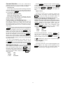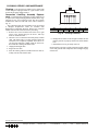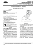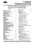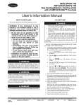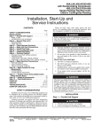
1
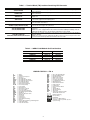
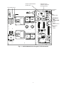
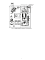
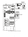
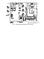
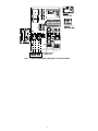
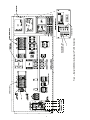
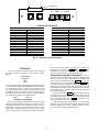
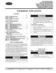
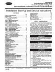
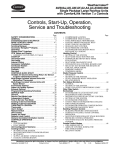
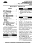
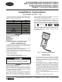
Air-Cooled Chillers with ComfortLink™ Controls
Water-Cooled Chillers with ComfortLink™ Controls
Rooftop Units with ComfortLink™ Controls
Navigator™ Accessory Display Module
Installation Instructions
Part Number 30GT-911---062
Read these instructions completely before attempting to install the Navigator Accessory Display Module. The Navigator
module is used on the following units:
UNIT
30HK
30HL
30HW
30RB
48AJ,AK,AW,AY
50AJ,AK,AW,AY
48PG
50PG
48ZG,ZN
48ZT,ZW,Z6,Z8
50ZG,ZN,Z2,Z3
50ZT,ZW,ZX,ZZ,Z6,Z7,Z8,Z9
SIZE
040-060
050-060
018-040
060-390
020-060
020-060
03-28
03-28
030-105
075-105
030-105
075-105
used to configure and perform service diagnostics on machines
equipped with Carrier ComfortLink controls.
The Navigator module keypad (see Fig. 1) contains eleven
menu LEDs and one Alarm Status LED, all of which are
red. The Navigator module is capable of displaying four
24-character lines of information on a back-lit liquid crystal
display. The Navigator module has four functional keys: the up
arrow (
), down arrow (
), ENTER , and ESCAPE
keys.
NOTE: The Navigator module should be removed after use.
There is not sufficient space to store the module in the unit
control panel. The module will NOT fit between the inner
panel and outer cover.
Com
fo
rtLin
k
CONTENTS
SAFETY CONSIDERATIONS . . . . . . . . . . . . . . . . . . . . . . 1
GENERAL . . . . . . . . . . . . . . . . . . . . . . . . . . . . . . . . . . . . . . . . 1
INSTALLATION . . . . . . . . . . . . . . . . . . . . . . . . . . . . . . . . 1-10
OPERATION . . . . . . . . . . . . . . . . . . . . . . . . . . . . . . . . . . 10, 11
CLEANING, SERVICE, AND MAINTENANCE . . . . . 12
SAFETY CONSIDERATIONS
Installation of this accessory can be hazardous due to system pressures, electrical components, and equipment location
(such as a roof or elevated structure).
Only trained, qualified installers and service technicians
should install, start up, and service this equipment.
When installing this accessory, observe precautions in the
literature, labels attached to the equipment, and any other
safety precautions that apply.
• Follow all safety codes.
• Wear safety glasses and work gloves.
• Use care in handling and installing this accessory.
To avoid the possibility of electrical shock, open and tag
all disconnects before installing this equipment. Be
aware that there may be more than one disconnect.
GENERAL
Check Package Contents — Check the accessory
package for missing parts or shipping damage. If damage is
found, or any part is missing, file a claim with the shipper
immediately. The package contains these instructions, carrying
bag, and the Navigator display module.
The Navigator module is a portable display that conforms to
NEMA (National Electrical Manufacturers Association) 4
specifications for outdoor use in temperatures ranging from
–22 F (–30 C) to 158 F (70 C). The Navigator module can be
MOD
E
Run
Alarm
Statu
Servi
s
Statu
s
ce Te
Temp
st
eratu
Pres
res
sure
s
Setpo
ints
Inputs
Outpu
ts
Confi
gura
tion
Time
Cloc
k
Oper
ating
Mode
Alarms
s
ESC
ENT
ER
a30-3924
Fig. 1 — Navigator in Display Mode
INSTALLATION
1. The Navigator display module is intended to be a mobile
device, so there are no holes in the device for permanent
mounting. The module has a magnetic mount that is
strong enough to hold the device in place on any clean,
dry metal surface.
2. The Navigator module is powered through the
ComfortLink Main Base Board (MBB). The Navigator
module has a modular telephone style (RJ14) connector
and should be connected to a specific terminal block in
the control box as found in Table 1. This device is intended for use on the LEN (Local Equipment Network) communications bus only. Do NOT connect the Navigator
module to the CCN (Carrier Comfort Network®) connector, as it may damage the device.
3. See Fig. 2-8 for Navigator LEN connection locations in
the units.
4. See Fig. 9 for Communication board details.
Manufacturer reserves the right to discontinue, or change at any time, specifications or designs without notice and without incurring obligations.
Catalog No. 533-00078
Printed in U.S.A.
Form 30/48/50-6SI
Pg 1
10-06
Replaces: 30G,H,R-1SI
Book 1 1 2 4 4
Tab 1a 1b 5c 6a 6b
Table 1 — Terminal Block (TB) Locations Containing LEN Connector
UNIT MODEL
LOCATION DESCRIPTION OF TB CONTAINING LEN CONNECTOR
30HK,HL040-060
30HW018-040
30RB060-120
30RB130-300
30RB315-390
48PG03-16 (TB1) 48PG20-28 (TB2)
50PG03-16 (TB1) 50PG20-28 (TB2)
48AJ,AK,AW,AY020-060
50AJ,AK,AW,AY020-060
48ZG,ZN,ZT,ZW,Z6,Z8
50ZG,ZN,ZT,ZW,ZX,ZZ,Z2,Z3,Z6,Z7,Z8,Z9
TB3 can be accessed without opening the control box door. It is located at the upper right corner
of the control box.
TB3 can be accessed without opening the control box door. It is located at the upper right corner
of the control box.
TB3 can be accessed by opening the control box door. It is located at the right side of the hinged
display door.
TB3 can be accessed by opening the left hand (smaller) door of the fan control panel. It is
located at the right side of the display panel.
Unit sizes 30RB315-390 are modular units and thus, accept two Navigator™ modules, one on
each unit module. See Table 2.
Both TBs are accessed by opening the control box door. TB1 (PG03-16) or TB2 (PG20-28) is
located in the lower right of the control box.
TB3 can be accessed by opening the control box door. It is located in the lower center of the
control box.
NOTE: If the unit is equipped with an Economizer Circuit Board (ECB), the ECB provides an
auxiliary RJ14 LEN connector. See product documentation for more detail.
TB3 can be accessed by opening the control box door. It is located to the left of the Scrolling
Marquee (display).
NOTE: These units provide an auxiliary RJ14 LEN connection on the corner post on the entering air end of the unit. See product documentation for more detail.
Table 2 — 30RB315-390 Modular Unit Combinations
UNIT SIZE
30RBA315
30RBA330
30RBA345
30RBA360
30RBA390
Module A
30RBA160
30RBA170
30RBA170
30RBA190
30RBA190
Module B
30RBA160
30RBA160
30RBA170
30RBA170
30RBA190
LEGEND FOR FIG. 2 - FIG. 8
A
AUX
C
CAP
CB
CB-FN
CB-HT
CB-P
CCB
CCN
CLHR
CR
CS
CSB
DS
ECB
EMM
EQUIP
EXV
EXVB
FB
FB1
FC
GCS
GND
HACR
IDR
IFC
—
—
—
—
—
—
—
—
—
—
—
—
—
—
—
—
—
—
—
—
—
—
—
—
—
—
—
—
Alarm
Auxiliary
Contactor, Compressor
Capacitor
Circuit Breaker
Circuit Breaker Fan Circuit
Circuit Breaker Cooler Heater
Circuit Breaker Pump
Control Circuit Board
Carrier Comfort Network
Cooler Heater Relay
Control Relay
Current Sensor
Current Sensor Board
Disconnect Switch
Economizer Circuit Board
Energy Management Module
Equipment
Electronic Expansion Valve
EXV Board
Fuse Block
Fan Board 1
Fan Contactor
Ground Current Sensing
Ground
Heating, Air Conditioning, and Refrigeration
Inducer Draft Relay
Indoor Fan Contactor
IFCB
MMC
MMR
OFC
PLP
RCB
LEN
MBB
NEC
PMP
POT
RRB
SW
TB
TDR
TRAN
TXV
—
—
—
—
—
—
—
—
—
—
—
—
—
—
—
—
—
Indoor Fan Circuit Breaker
Motormaster® Contactor
Motormaster Relay
Outdoor Fan Contactor
Phase Loss Protection
Rooftop Control Board
Local Equipment Network
Main Base Board
National Electrical Code
Pump Contactor
Potentiometer
Reverse Rotation Board
Switch
Terminal Block
Time-Delay Relay
Transformer
Thermostatic Expansion Value
Terminal Block Connection
Field Power Wiring
Factory Wiring
Field Wiring
Accessory or Option Wiring
To indicate common potential only, not to
represent wiring
2
SETPOINT POTENTIOMETER
(EXPORT ONLY)
MARQUEE DISPLAY
(DOMESTIC-STANDARD)
(EXPORT-OPTIONAL)
FIELD POWER SUPPLY
SEE OTHER
LABELS
CCN
CONNECTIONS
NAVIGATOR
LEN
CONNECTION
ENABLE
ON/OFF
CONTACT SWITCH
EMERGENCY
ON/OFF
SWITCH
a30-4460
Fig. 2 — 30HK,HL040-060 Units Navigator™ LEN Connection
3
MARQUEE DISPLAY LOCATION
NAVIGATOR LEN
CONNECTION
CCN
a30-4461
Fig. 3 — 30HW018-040 Units Navigator™ LEN Connection
4
NAVIGATOR LEN
CONNECTION
CCN
NON-FUSED
DISCONNECT
OPTION
a30-4462
Fig. 4 — 30RB060-120 Units Navigator™ LEN Connection
5
NAVIGATOR LEN
CONNECTION
CCN
Fig. 5 — 30RB130-300 Units Navigator™ LEN Connection
a30-4463
6
CCN
a48-8278
NAVIGATOR LEN CONNECTION
Fig. 6 — Typical 48/50PG Series Navigator™ LEN Connection
7
CONTROLS OPTION BOARD
CCN
NAVIGATOR LEN
CONNECTION
Fig. 7 — Typical 48/50A Series Navigator™ LEN Connection
8
a48-8279
9
Fig. 8 — Typical 48/50Z Series Navigator™ LEN Connection
CCN
NAVIGATOR LEN
CONNECTION
a48-8280
PLUG TERMINAL
1
8
LEN
(+)
(COM)
(-)
CCN
CCN
SHIELD
a30-4464
TERMINAL BLOCK DETAIL
30 Series Chillers (HK,HL,HW,RB)
PLUG TERMINAL
TRACE TO
PIN 1
LEN PLUG, PIN 2
PIN 2
LEN PLUG, PIN 3
PIN 3
LEN PLUG, PIN 5
PIN 4
LEN PLUG, PIN 1
PIN 4
CCN PLUG, PIN 1
PIN 5
LEN PLUG, PIN 6
PIN 5
CCN PLUG, PIN 6
PIN 6
CCN PLUG, PIN 5
PIN 6
CCN SCREW ‘-’
PIN 7
CCN PLUG, PIN 3’
PIN 7
CCN SCREW ‘COM’
PIN 8
CCN PLUG, PIN 2
PIN 8
CCN SCREW ‘+’
Packaged Rooftop Units (PG,A,Z)
PLUG TERMINAL
TRACE TO
PIN 1
CCN SCREW ‘-’
PIN 1
CCN PLUG, PIN 5
PIN 2
CCN SCREW ‘COM’
PIN 2
CCN PLUG, PIN 3’
PIN 3
CCN SCREW ‘+’
PIN 3
CCN PLUG, PIN 2
PIN 4
CCN PLUG, PIN 6
PIN 4
LEN PLUG, PIN 6
PIN 5
CCN PLUG, PIN 1
PIN 5
LEN PLUG, PIN 1
PIN 6
LEN PLUG, PIN 5
PIN 7
LEN PLUG, PIN 3
PIN 8
LEN PLUG, PIN 2
Fig. 9 — Communication Board Detail
returns to the default display mode after 60 seconds of no
keypad activity. Pressing the ENTER and ESCAPE keys
simultaneously while the unit displays “Select a menu item”
will also return the device to its default display mode.
OPERATION
To use the Navigator™ module, plug the RJ14 connector
into the LEN port. On power up, the Navigator module
displays:
ComfortLink
Navigator
By
Carrier
Navigating through Menu Structures — The arrow keys are used to scroll through the tiered command menu
structure. See the base unit Controls, Start-Up, Operation, and
Service Guide for menu structure. The ENTER key is used to
select a menu item or to accept data entry. The ESCAPE key
is used to exit to the next highest command level (mode) or to
cancel data entry. The sub-mode and item displays will wrap
around with the last and first items separated by a line of dashes
on the display. The ‘>’ symbol is the pointer and is located at
the left side of the display.
At any time, press the ESCAPE key repeatedly as needed
to display “Select a menu item” on the screen. This is the top
level and the arrow keys are used to move the red LED to one
of the 11 desired modes. Press ENTER to display the submodes within a top level mode.
Use the arrow keys to move the pointer (‘>’) to the desired
sub-mode. Up to four sub-modes will be displayed on the
Navigator module at one time. Continue pressing the arrow
keys as needed to find the desired sub-mode.
The Navigator module will upload the appropriate display
tables from the Main Base Board (MBB) that it is connected to.
A ‘Communication failure’ message will be displayed if any
errors are encountered. Check the wiring at the connector and
the MBB-J5 plug if necessary. After successful upload of
information, the Navigator module begins its default display.
An example of the display in the default mode is:
EWT
54.2 °F
ENTERING FLUID TEMP
The entire local display command structure can be accessed
with the Navigator module. Pressing any key while in the default display mode will cause the Navigator module to enter its
manual mode. In this mode, all sub-modes and items of the
local display command structure, denoted on the display
screen, can be accessed. The Navigator module automatically
10
Password Protection — If an area is entered that is
password protected or an item is selected for change that is
password protected, the Navigator™ module will display:
Enter Password
The first digit of the password will be flashing. Hold either
of the arrow keys down to change the value of the first digit (if
necessary) and press ENTER to accept. Repeat the process for
the remaining three digits.
Password for 30RB units is 0111.
Password for all other units is 1111.
The message “Invalid Password” is displayed if the password is not correct. The password can be disabled from the
Navigator module, and can be changed.
Pressing ENTER will cause the “OFF” to flash. Use the up
or down arrow to change “OFF” to “ON”. Pressing ENTER
will illuminate all LEDs and display all pixels in the view
screen. Pressing ENTER and ESCAPE simultaneously allows the user to adjust the display contrast. The display will
read:
Adjust Contrast
---+-----------Use the up or down arrows to adjust the contrast. The
screen’s contrast will change with the adjustment. Press
ENTER to accept the change. The Navigator module will
keep this setting as long as it is plugged in to the LEN bus.
Forcing Values and Configuring Items — Cer-
backlight of the display can be adjusted to suit ambient lighting
conditions. The factory default is set to the highest level. To adjust the backlight of the Navigator module, press the
ESCAPE key until the display reads, “Select a menu item.”
Using the arrow keys, scroll to the Configuration mode
and press ENTER . Using the arrow keys, scroll to “DISP”
(display) and press ENTER . The display will read:
>TEST
OFF
METR
OFF
LANG
ENGLISH
Adjusting the Backlight and Brightness — The
tain items are allowed to be forced and other items are
user-configurable. Both of these changes can be made using
the Navigator module. See the unit’s Control, Start-Up, Service
and Troubleshooting Guide for a list of forcible and configurable values.
To force an item, position the pointer at the item. Press the
ENTER key and if the point can be forced or configured, its
current value will flash. Use the arrow keys to adjust the temperature to the desired value. Press the ENTER key when
finished. The Navigator module will display a lowercase ‘f’ to
the right of the value if it has been forced. If no ‘f’ is displayed,
the item was configurable. To clear a force, press ENTER so
that the value is again flashing. Simultaneously press the up
and down arrow keys. The value will stop flashing, the ‘f’ will
be removed, and the parameter will revert to its corresponding
input channel value.
To edit a user-configurable item, operate the unit in
Service Test mode, or reset current alarms or history, and use
the ENTER key to make the value flash. Next, use the arrow
keys to adjust the item to the desired value and press ENTER .
ADJUSTING BRIGHTNESS — Pressing ENTER will
cause the “OFF” to flash. Use the up or down arrow keys to
change “OFF” to “ON”. Pressing ENTER will illuminate all
LEDs and display all pixels in the view screen. Pressing
and
simultaneously allows the user to adjust the display
brightness. The display will read:
Adjust Brightness
---------------+
Use the up or down arrow keys to adjust the brightness. The
screen’s brightness will change with the adjustment. Press
ENTER to accept the change. The Navigator module will
keep this setting as long as it is plugged in to the LEN bus.
Adjusting the Contrast — The contrast of the display
can be adjusted to suit ambient conditions. To adjust the contrast of the Navigator module, press the ESCAPE key until
the display reads, “Select a menu item.” Using the arrow keys,
scroll to the Configuration mode and press ENTER . Using the
arrow keys, scroll to “DISP” (display) and press ENTER . The
display will read:
>TEST
OFF
METR
OFF
LANG
ENGLISH
11
CLEANING, SERVICE, AND MAINTENANCE
TAB
Cleaning — The Navigator™ module can be cleaned with
a mild detergent. Isopropyl alcohol or a glass cleaner can be
used on all Navigator module surfaces.
Connection Cord/Plug Assembly Replacement — If the RJ14 plug is damaged, it can be replaced. If it
is replaced, the wiring to the plug must be identical to the original plug. Use Fig. 10 to record wire color. The wire sequence
should be the same for both ends of the cable as shown in
Fig. 10.
The connection cable (P/N 912-990010-2) can be replaced
if damaged. Replacement cables are available from
Replacement Components Division. Remove the Navigator
module from the LEN connection before proceeding.
1. Remove the 6 screws from the back of the case to gain
access to the internal plug for the device, and keep
them for installation later.
2. The back cover is connected to the touch pad by a ribbon
cable. The ribbon cable is not long enough to allow the
two halves to be completely separated. To be able to access the plug connection, slightly offset the back cover.
Be careful not to damage the ribbon cable.
3. Unplug the damaged cable.
4. Plug in the new cable.
5. Insert the rubber grommet (included with new cable assembly) into the cable entrance hole.
PIN
PIN
1
1
2
2
3
4
3
5
6
4
5
6
Wire Color
Fig. 10 — Pin/Plug Assembly
6. Realign the two halves of the Navigator module. Be sure
that the grommet is properly seated in the cable entrance
hole.
7. Reinstall the 6 screws previously removed.
NOTE: Failure to properly seal the Navigator module with the
screws and grommet will compromise the watertight integrity
of the device.
Copyright 2006 Carrier Corporation
Manufacturer reserves the right to discontinue, or change at any time, specifications or designs without notice and without incurring obligations.
Catalog No. 533-00078
Printed in U.S.A.
Form 30/48/50-6SI
Pg 12
10-06
Replaces: 30G,H,R-1SI
Book 1 1 2 4 4
Tab 1a 1b 5c 6a 6b