1
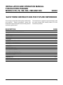
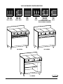
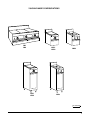
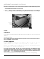
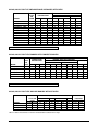
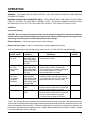
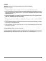
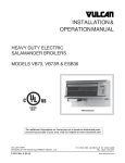
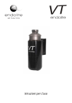
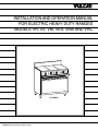
INSTALLATION AND OPERATION MANUAL
FOR ELECTRIC HEAVY DUTY RANGES
MODELS VR, VS, VM, VEX, VMX AND VRC
VR SERIES
VULCAN-HART COMPANY, P.O. BOX 696, LOUISVILLE, KY 40201- 0696, TEL. (502) 778-2791
FORM 30820 (6-93) (Formerly 112685 & 112781)
2
INSTALLATION AND OPERATION MANUAL
FOR ELECTRIC RANGES
MODELS VR, VS, VM, VEX, VMX AND VRC
INDEX
SAVE THESE INSTRUCTIONS FOR FUTURE REFERENCE
Vulcan ranges are produced with quality workmanship
and material. Proper installation, usage and
maintenance of your range will result in many years of
satisfactory performance.
DESCRIPTION
INDEX
VULCAN RANGE CONFIGURATIONS
GENERAL
INSTALLATION
UNPACKING
LOCATION
BUMPER BAR INSTALLATION
LEVELING
ELECTRICAL CONNECTIONS
OPERATION
CONTROLS
BEFORE FIRST USE
USING THE RANGE TOP
USING THE VR SERIES OVEN
USING THE VRC SERIES OVEN
OPERATING HINTS
COOKING TIPS
CLEANING
CLEANING BLOWER WHEEL
The manufacturer suggests that you thoroughly read
this entire manual and carefully follow all of the
instructions provided.
PAGE
3
4
6
7
7
7
8
8
8
11
11
12
12
13
13
14
14
15
15
3
VULCAN RANGE CONFIGURATIONS
VR1, VR2
VM1, VM2
VS1, VS2
VR1C, VR2C
VR3, VR6
VM3, VM6
VS3, VS6
VR3C, VR6C
VR5
VM5
VS5
VR5C
VR4
VM4
VS4
VR4C
VR SERIES
VRC SERIES
VS SERIES
4
VR3, VR6
VR7
VM3, VM6
VM7
VS3, VS6
VS7
VR3C, VR6C
VR7C
(SHOWN WITH OPTIONAL
HIGH SPEED ELEMENTS)
PL - 51130-1
VULCAN RANGE CONFIGURATIONS
VM1
VM2
VMX1
VMX2
VEX1
VEX2
VMX3
VEX3
PL - 51130-2
5
GENERAL
The various Vulcan electric VR, VS, VM, VEX and VMX Family Series standard ranges and VRC Series
convection ranges are equipped as follows:
MODEL
DESCRIPTION
RANGES WITH STANDARD OVEN
VR1
VR2
VR3
VR4
VR5
VR6
VR7
(3) 12" x 24" hot tops.
(3) 12" x 24" all purpose plates, (2) with grease troughs on right and left sides and (1) without
grease trough in the center.
(2) 91/2" dia. round French hot plates at left and (2) 12" x 24" hot tops at center and right.
(6) 91/2" dia. round French hot plates.
36" wide griddle with front grease trough.
(2) 91/2" dia. round French hot plates at left and (2) 12" x 24" all purpose plates at center and right.
(2) 91/2" dia. round French hot plates at left and 24" griddle top at right.
MODULAR RANGES WITHOUT OVEN
VM1
VM2
VM3
VM4
VM5
VM6
VM7
(3) 12" x 24" hot tops.
(3) 12" x 24" all purpose plates, (2) with grease troughs on right and left sides and (1) without
grease trough in the center.
(2) 91/2" dia. round French hot plates at left and (2) 12" x 24" hot tops at center and right.
(6) 91/2" dia. round French hot plates.
36" wide griddle with front grease trough.
(2) 91/2" dia. round French hot plates at left and (2) 12" x 24" all purpose plates at center and right.
(2) 91/2" dia. round French hot plates at left and 24" griddle top at right.
12" WIDE FULL BODY EXPANDO RANGES
VEX1
VEX2
VEX3
(1) 12" x 24" hot top.
(1) 12" x 24" all purpose plate with side grease troughs.
(2) 91/2" dia. round French hot plates.
12"WIDE MODULAR EXPANDO RANGE
VMX1
VMX2
VMX3
(1) 12" x 24" hot top.
(1) 12" x 24" all purpose plate with side grease troughs.
(2) 91/2" dia. round French hot plates.
RANGES WITH CONVECTION OVEN
VR1C
VR2C
VR3C
VR4C
VR5C
VR6C
VR7C
6
(3) 12" x 24" hot tops.
(3) 12" x 24" all purpose plates, (2) with grease troughs on right and left sides and (1) without
grease trough in the center.
(2) 91/2" dia. round French hot plates at left and (2) 12" x 24" hot tops at center and right.
(6) 91/2" dia. round French hot plates.
36" wide griddle with front grease trough.
(2) 91/2" dia. round French hot plates at left and (2) 12" x 24" all purpose plates at center and right.
(2) 91/2" dia. round French hot plates at left and 24" griddle top at right.
MODEL
DESCRIPTION
RANGES WITH CABINET BODY
VS1
VS2
VS3
VS4
VS5
VS6
VS7
(3) 12" x 24" hot tops.
(3) 12" x 24" all purpose plates, (2) with grease troughs on right and left sides and (1) without grease
trough in the center.
(2) 91/2" dia. round French hot plates at left and (2) 12" x 24" hot tops at center and right.
(6) 91/2" dia. round French hot plates.
36" wide griddle with front grease trough.
(2) 91/2" dia. round French hot plates at left and (2) 12" x 24" all purpose plates at center and right.
(2) 91/2" dia. round French hot plates at left and 24" griddle top at right.
Hot tops and all purpose plates are not recommended for use as griddles.
Optional high speed elements are available in place of round French hot plates for use with 208/240 volts only. The
high speed elements are not recommended for stock pot work.
All VR and VRC ranges with oven sections are mounted on 6" adjustable legs. Optionally, they may be equipped
with no legs (for masonry base mounting) or a 4" toe base in place of legs.
All VR ranges with ovens are equipped with one oven rack. All VRC ranges with ovens are equipped with 3 oven racks.
Additional racks may be purchased as an option.
All VR and VRC ranges with full size ovens, VS cabinet base or VM modular ranges will have two drawers in the front
of the range under the cooking top area. The left-hand drawer is a baffled grease drawer, the right-hand drawer is
a warming drawer.
INSTALLATION
UNPACKING
Immediately after unpacking the range, check it for possible shipping damage. If the range is found to be
damaged after unpacking, save the packing material and contact the carrier within 15 days of delivery.
Prior to installation, verify that the electrical service agrees with the specifications on the data plate which is
located on the breaker cover door to the right of the oven cavity.
LOCATION
Position the range in its final installation position. Refer to the data plate for required clearances adjacent to
combustible and non-combustible construction. When a broiler is installed over the range, refer to the broiler
and range data plates for clearance requirements. Install the range so that the conduit can be placed into the
bottom entrance.
The VRC Convection Range will require a minimum 4" clearance between a rear wall and motor cover. The
convection oven also comes equipped with 9" wide, side bumper bars that must be attached to the range if it is
installed next to a combustible wall. Refer to BUMPER BAR INSTALLATION in this manual.
7
BUMPER BAR INSTALLATION (RANGES ON CASTERS ONLY)
There are 2 sets of bumper bars packaged separately and placed inside the oven compartment for shipping. Bumper
bars must be installed on the side(s) of the convection oven that is placed near a combustible wall during operation.
1. Remove bumper bars from the oven cavity and unwrap.
2. Using a 5⁄16" socket and socket driver, attach bumper bar to the side(s) of the oven nearest the combustible wall.
Note that there are predrilled bumper bar mounting holes supplied on the sides and back of the oven (Fig. 1).
Bumper Bar
Mounting
Location
Bumper Bar
Mounting
Location
PL-40033-1
Fig. 1
LEVELING
Full Body Ranges
Using a carpenter's level placed on top of the range, adjust the feet so the range is level from front to back and from
side to side.
Masonry Base/Toe Base
Using a carpenter's level, ensure that the base where the range will be installed is level. If the base is not level, it
must be levelled before installing the range.
ELECTRICAL CONNECTIONS
WARNING: ELECTRICAL AND GROUNDING CONNECTIONS MUST COMPLY WITH THE APPLICABLE
PORTIONS OF THE NATIONAL ELECTRICAL CODE AND/OR OTHER LOCAL ELECTRICAL CODES.
WARNING: DISCONNECT ELECTRICAL POWER SUPPLY AND PLACE A TAG AT THE DISCONNECT SWITCH
TO INDICATE THAT YOU ARE WORKING ON THE CIRCUIT.
Bring conduit containing the proper supply wire (size and type in accordance with latest edition of the National
Electrical Code ANSI/NFPA-70) to the range through the 2" hole located in the bottom of the range. On modular
ranges and expando units, the conduit enters the range through the clearance hole located in the back of the range.
Use wire suitable for 75°C on ranges carrying more than 80 amps.
Connect the supply leads to the terminal block and the green grounding lead to the labeled ground lug.
8
ELECTRICAL DATA CHARTS
VR RANGES WITH STANDARD OVENS OR VS RANGES WITH CABINET BODY
"N/A" RANGES NOT AVAILABLE 480 VOLT
3 PHASE LOAD
TOTAL KW PER PHASE
KW 208V 240V 480V
MODEL
CONN. X-Y Y-Z X-Z
VR1,2,5
21.7 7.7
5
9
VR1,2,5 / VB73
27.7 10.7
8
—
VS,VM1,2,5
15
5
5
5
VS,VM1,2,5 / VB73
21
8
8
—
VR3,6,7
20.7 7.7
5
8
VR3,6,7 / VB73
26.7 10.7
8
—
VS,VM3,6,7
14
5
5
4
VS,VM3,6,7 / VB73
20
8
8
—
VR4
18.7 6.7
4
8
VR4 / VB73
24.7 9.7
7
8
VS,VM4
12
4
4
4
VS,VM4 / VB73
18
7
7
—
480 Volt Only:
VR1,2,5 / VB73
21.7 7.7
11
9
VR3,6,7 / VB73
26.7 7.7
11
8
VS,VM1,2,5 / VB73
21
5
11
5
VS,VM3,6,7 / VB73
20
5
11
4
VR4 / VB73
24.7 6.7
10
8
VS,VM4 / VB73
18
4
10
4
X
70
82
42
54
65
78
38
50
61
74
33
46
208V
Y
53
78
42
67
53
78
42
67
45
70
33
58
—
—
—
—
—
—
—
—
—
—
—
—
NOMINAL AMPS PER LINE WIRE
3 PHASE
240V
480V
Z
X
Y
Z
X
Y
Z
58
60
46
51
30
23
25
71
71
68
61
—
—
—
42
36
36
36
18
18
18
54
47
58
47
—
—
—
54
57
46
47
28
23
24
67
68
68
58
—
—
—
38
33
36
33
16
18
16
50
43
58
43
—
—
—
50
53
39
43
19
27
22
63
64
60
54
27
30
33
33
29
29
29
14
14
14
46
40
51
40
—
—
—
—
—
—
—
—
—
—
—
—
—
—
—
—
—
—
—
—
—
—
—
—
—
—
—
30
28
18
16
27
14
34
34
29
29
30
25
36
34
29
27
33
25
1 PHASE
208V 240V 480V
XYZ XYZ XYZ
104 90
45
133 115 —
72
63
31
101 88
—
99
86
43
128 111 —
67
58
29
96
83
—
90
78
39
119 103 N/A
58
50
25
87
75
—
—
—
—
—
—
—
—
—
—
—
—
—
N/A
N/A
44
42
N/A
38
VR RANGES WITH CONVECTION OVENS
MODEL
VR1C,2C,5C
VR1C,2C,5C/VB73
VR3C,6C,7C
VR3C,6C,7C/VB73
VR4C
VR4C/VB73
3 PHASE LOAD
TOTAL KW PER PHASE
KW 208V,240V & 480V
CONN. X-Y Y-Z X-Z
22
6.2 6.2 9.6
28
9.2 9.2 9.6
21
6.2 6.2 8.6
27
9.2 9.2 8.6
19
5.2 5.2 8.6
25
8.2 8.2 8.6
X
66
78
62
74
58
70
NOMINAL AMPS PER LINE
3 PHASE
208V
240V
Y
Z
X
Y
Z
51
66
57
45
57
76
78
68
66
68
51
62
54
45
54
76
74
64
66
64
43
58
50
37
50
68
70
61
59
61
WIRE
X
11
—
8
NOMINAL AMPS PER LINE WIRE
3 PHASE
1 PHASE
208V
240V
480V
208V 240V 480V
Y
Z
X
Y
Z
X
Y
Z
XYZ XYZ XYZ
21
11
9
18
9
4.5 9.0 4.5
24
21 10.4
—
—
—
—
—
—
—
—
24
21 10.4
17
8
7
14
7
3.6 7.2 3.6
19
17
8.3
X
29
34
27
32
25
30
480V
Y
22
33
22
33
19
29
Z
29
34
27
32
25
30
1 PHASE
208V 240V
XYZ XYZ
106 92
135 117
101 87
130 112
91
79
120 104
VEX AND VMX RANGES
MODEL
VEX,VMX1
VEX2,VMX2
VEX3,VMX3
3 PHASE LOAD
TOTAL KW PER PHASE
KW 208V 240V 480V
CONN. X-Y Y-Z X-Z
5
2.5 2.5
—
5
—
—
—
4
2
2
—
"VB73" in above charts denotes an electric elevated broiler installed over the range.
9
220/380, 240/415 VOLT VS/VM RANGES AND VR RANGES WITH OVEN
MODEL
VR1,2,5
VR1,2,5 / VB73
VS,VM1,2,5
VS,VM1,2,5 / VB73
VR3,6,7
VR3,6,7 / VB73
VS,VM3,6,7
VS,VM3,6,7 / VB73
VR4
VR4 / VB73
VS,VM4
VS,VM4 / VB73
TOTAL
KW
CONN.
21.7
27.7
15
21
20.7
26.7
14
20
18.7
24.7
12
18
3 PHASE LOAD
KW PER PHASE
X-N
7.7
10.7
5
8
6.7
9.7
4
7
6.7
9.7
4
7
Y-N
5
8
5
8
5
8
5
8
4
7
4
7
Z-N
9
9
5
5
9
9
5
5
8
8
4
4
NOMINAL AMPS PER LINE WIRE
240/415 VOLT
3 PHASE
1 PHASE
X
Y
Z
X
Z
32
21
38
32
58
45
33
38
45
71
21
21
21
21
42
33
33
21
33
54
28
31
38
28
59
41
33
38
41
71
17
21
21
17
42
29
33
21
29
54
28
17
33
28
50
41
29
33
41
62
17
17
17
17
34
29
29
17
29
46
VOLTAGE FROM ANY PHASE TO NEUTRAL NOT TO EXCEED 250 VOLTS
220/380, 240/415 VOLT VRC RANGES WITH CONVECTION OVEN
TOTAL
KW
MODEL
CONN.
VR1C,2C,5C
22
VR1C,2C,5C/VB73
28
VR3C,6C,7C
21
VR3C,6C,7C/VB73
27
VR4C
19
VR4C/VB73
25
3 PHASE LOAD
KW PER PHASE
X-N
6.2
9.2
6.2
9.2
5.2
8.2
Y-N
6.2
9.2
6.2
9.2
5.2
8.2
Z-N
9.6
9.6
8.6
8.6
8.6
8.6
X
33
40
31
37
31
37
NOMINAL AMPS PER LINE WIRE
3 PHASE
220/380V
240/415V
Y
Z
X
Y
Z
25
33
34
26
34
38
40
41
39
41
23
33
32
24
34
35
38
38
37
39
21
33
32
22
34
33
38
38
34
39
1 PHASE
X
34
41
32
38
32
38
VOLTAGE FROM ANY PHASE TO NEUTRAL NOT TO EXCEED 250 VOLTS
220/380, 240/415 VOLT VEX AND VMX RANGES WITHOUT OVEN
MODEL
VEX,VMX1
VEX2,VMX2
VEX3,VMX3
TOTAL KW
CONN.
220/380 240/415
4.2
5
4.2
5
3.4
4
NOMINAL AMPS PER LINE WIRE
1PH,3-WIRE
2-WIRE
1PH,3-WIRE
2-WIRE
220/380
220
240/415
240
L1
L2
L1
L1
L2
L1
9.6
9.6
19.3
10.5
24
21
19.3
—
19.3
21
—
21
7.8
7.8
15.6
8.5
19
17
"VB73" in above charts denotes an electric elevated broiler installed over the range.
10
LOAD
KW/PHASE
1 PHASE
L1-N
L2-N
2.5
2.5
—
—
2.0
2.0
Z
60
80
58
76
56
73
OPERATION
WARNING: THE RANGE AND ITS PARTS ARE HOT. USE CARE WHEN OPERATING, SERVICING AND
CLEANING THE RANGE.
WARNING (CONVECTION OVEN MODELS ONLY): WHEN USING CONVECTION OVENS, DO NOT STAND
DIRECTLY IN FRONT OF OVEN WHILE OPENING DOOR. ALTHOUGH OPENING OVEN DOOR WILL
AUTOMATICALLY SHUT OFF THE FAN, SOME HEAT ESCAPES. STEP AWAY TO AVOID HOT AIR.
CONTROLS
Top Surface Elements
CAUTION: Do not continuously operate surface units at maximum temperature; maximum temperature
operation will be required only during peak cooking intervals. Reduce heat during slow cooking periods to
save energy and prolong the life of the heating elements and castings.
Element Switches — control and maintain heat to surface elements.
Element Indicator Lights — when lit, indicates power is being supplied to the element.
There are 3 different types of plates that may be used in the VR, VS, VRC, VM, VEX and VMX Ranges.
PLATE & SIZE
Hot Top
12" X 24"
All Purpose Top
12" X 24"
with/without
trough
91/2" Dia. French
Hot Plates
(or Optional
Hi-Speed
Elements)
Griddle Top 36"
Griddle Top 24"
USED IN
MODELS
VR1,VR3,VM1,
VM3,VMT1,VMT3,
VEX1,VEX3,VMX1,
VMX3,VR1C,VR3C,
VS1,VS3
VR2,VR6,VM2,
VM6,VTM2,VTM6,
VEX2,VEX6,VMX2,
VMX6,VR2C,VR6C,
VS2, VS6
VR3,VR4,VR6,VR7
VM3,VM4,VM6
VTM3,VTM4,VTM6,
VEX3,VEX4,VEX6
VR3C,VR4C,VR6C,
VS3,VS4,VS6
VR5,VM5,VS5,
VR5C
VR7,VM7,VS7,
VR7C
CONTROLS
3-heat switch provides control of a single
element rated at 5 KW.
TEMP.
RANGE
340 to 800°F
Thermostat provides control of a single
element rated at 5 KW. Indicator light
(next to thermostat) is ON when thermostat
calls for heat and goes OFF when
desired temperatire is reached.
Infinite switch (3-heat switch in 480 V.
models) provides (according to its setting)
a varying percent (about 7-100%) of its total
input to the elements. Rated at 2 KW.
340 to 800°F
(3) thermostats control heat to (3) individual
elements rated at 5 KW each. Each thermostat has its own indicator cycling light.
(2) thermostats control heat to (2) individual
elements rated at 5 KW each. Each thermostat has its own indicator cycling light.
(2) infinite switches rated at 2 KW each.
175-550°F
*
175-550°F
*
*The 91/2" dia. French plates have separate thermostats built into each energy saving plate. With the thermostat dial
set at the highest available temperature and pan or pot containing food placed on the plate, the plate will deliver 2,000
watts at a temperature lower than 800°F. When the cooking utensil is removed or its contents have boiled dry, the
heating watts are lowered as the temperature rises. Example: When the plate reaches from 820°F to 850°F, wattage
is cut back to 950 watts, a 52.5% reduction.
11
Oven Controls
Thermostat — (located on the right side of the switch panel) controls and maintains oven temperature around the
desired set temperature. Temperature range of the oven is from 175°F to 550°F.
VRC Oven ON-OFF Switch (Convection Oven) — a rocker-type switch that works in conjunction with the electric
supply of the thermostat and heating elements operating the oven. This switch must be in the ON position for the
oven to operate.
3-Heat Switch (VR Ranges with Standard Ovens Only) — There is one 3-heat switch located to either side of the
oven thermostat dial. The left switch controls the rate of temperature build-up for the 2700 total watts of the inner
and outer top oven elements, and the right switch controls the heating build-up of the 4000 total watts of the inner
and outer bottom oven elements. At HI power, both elements (top and bottom) are at maximum output. At MED
power, the inner elements (top and bottom) are at half power. At LO power, the inner and outer elements (top and
bottom) are heating in series at about one-quarter power.
Oven Indicator Light — (located next to the thermostat) when lit, indicates the thermostat is calling for heat and when
OFF, indicates the desired temperature is reached.
BEFORE FIRST USE
Clean off the rust preventive compound on the surface units with a cloth dampened with a grease solvent. Wipe with
a clean, damp cloth, then dry thoroughly.
Seasoning
The cast iron surface plates must be seasoned. To do this, grease top, then turn element switches to LO (or
thermostat to 300°F) and allow plates to heat up gradually for about 2 hours. Repeat this procedure a second time
before regular use. Seasoning the surface plates will deter cracking of the cast iron and ensure a longer life.
USING THE RANGE TOP
Use the high setting for bulk cooking jobs or to bring food quickly up to its cooking temperature, then reduce to the
actual cooking temperature. During slow cooking periods, reduce plate temperature to idle around 200°F (or set 3heat switch to MED).
12" x 24" Hot Top
Each hot top section has an independent control allowing adjustment to HI-MED-LO temperature settings. The hot
top surface is best suited for stock pot work.
When ready to use the hot top section, wipe the surface clean of all grease and food particles. Position utensils so
that as much of the hot top section area as possible is covered. Set control at desired dial setting.
12" x 24" All Purpose Top
Each all purpose top section is independently operated by a separate thermostat allowing a variety of temperature
settings for sauteing, braising, pan frying and skillet work.
When ready to use the all purpose top section, wipe the surface clean of all grease and food particles. Position
utensils so that as much of the hot top section area as possible is covered. Set control at desired dial setting.
12
French Hot Plate
French hot plates are designed for bulk cooking and stock pot work (up to 20 Qt. stock pots or 9-10" dia. pans). Stock
pots of over 5-gallon capacity are not recommended for continuous use on French hot plate sections. 208/240 volt
units are controlled by infinite heat switches. 480 volt models are controlled by 3-heat switches.
Optional High-Speed Units
High-speed units furnished in lieu of French hot plates on 208 and 240 volt models are controlled by infinite switches.
Griddle
Use for general griddling (hamburgers, eggs, pancakes, minute steaks, etc.) If using for the first time, griddle must
be seasoned (see BEFORE FIRST USE in this manual).
To use, set dial at desired temperature and allow griddle to preheat (about 7 minutes to reach 350°F). Indicator light
will go off when preset temperature is reached. Then load and cook according to recipe, turning foods halfway
through cooking time (unless recipe specifies otherwise).
Each 12" section of the griddle has its own thermostatically controlled heat zone and indicator light. This permits
simultaneous cooking of different foods at different temperatures (such as eggs, 300°F; and bacon, 350°F); or using
the entire griddle top at the same temperature; or using only one or two sections during off-peak periods for
economical operation.
USING THE VR SERIES OVEN
When baking or roasting on one level only, remove rack and place food pans directly on oven deck. When using rack
and deck at the same time, rotate foods halfway through cooking cycle. When baking on the rack, it may be necessary
to set the bottom 3-heat switch at HI.
Preheat oven. Set top and bottom 3-heat switches to HI and thermostat to desired baking temperature. Keep oven
door closed during preheating. While waiting for the oven to preheat, load food products into pans.
When set temperature is reached, allow oven signal light to go on and off at least twice so the oven is thoroughly
heated and will brown baked products evenly. Set 3-heat switches at desired setting. Load oven as quickly as
possible to reduce heat loss from open door. Place pans in center of rack and close door. Do not load small pans
closer than 3" from door. Do not let pans touch the sides or back of the oven or each other.
When cooking is completed, open oven door and unload product. After oven cools, wipe up any spills as quickly as
possible to prevent them from becoming stubborn stains.
USING THE VRC SERIES OVEN
The convection oven operates like the standard VR oven except that it is controlled by an ON-OFF rocker switch
instead of 3-heat switches. The ON-OFF switch must be in the ON position for the oven to operate. In addition,
cooking times are generally reduced by 5-10 minutes and the cooking temperature is usually about 25°F lower than
standard recipes will indicate.
Best results will normally be achieved by using rack positions 1, 3 and 5 for sheet pan cooking, or rack positions 2
and 4 for larger food products. Further time, temperature and rack adjustments may be required, depending upon
your particular product and cooking load.
13
To operate the convection oven, arrange oven racks as required, turn the power switch to ON and set the thermostat
dial to the desired temperature setting. Allow the oven indicator light to cycle on and off at least twice to ensure that
the oven has reached the preset cooking temperature. Load product as quickly as possible. Place pans on center
of racks.
After cooking is completed, open oven door and unload product. After oven cools, wipe up any spills as quickly as
possible to prevent them from becoming stubborn stains.
OPERATING HINTS
Preheat the oven and surface units to cooking temperature before cooking the product. Become familiar with the
function of the controls and the area of their operation.
Avoid excessive door opening. Also avoid direct air current on the oven.
Use flat-bottomed, straight-sided pots and pans.
Use covers for stock pot work. Water will boil much sooner and much less heat is required for cooking in a covered
container.
Turn high speed elements off a few minutes before cooking is completed to use the heat stored in the element.
After each cooking load, scrape excess food and fat particles off the griddle surface, using a flexible spatula or wire
brush.
COOKING TIPS
VR Oven
While it is recommended that the 3-heat switches be set to the HI position in order to preheat the oven to the desired
temperature, it is necessary for some baking products to turn the 3-heat switch controlling the top elements to the
MED or LO position in order to reduce the amount of radiant heat applied to the product so that the top portion of the
product will not be burned.
Uneven cooking may be prevented by different settings for the top and bottom oven 3-heat switches. The amount
of heat applied to a product inside the oven is affected not only by the setting of the thermostat and 3-heat switches,
but also by its position inside the oven and the frequency of opening and closing the oven door.
Meat roasting is best performed in a balanced oven; 3-heat switch positions of HI and HI are suggested, with the
thermostat setting at the low temperature recommended by the American Meat Institute and the Department of
Agriculture. Top heat results in a well colored or carmelized finish to meats. When roasting fowl and a heavily
browned appearance is not desired, set the top 3-heat switch at MED or LO. It is recommended that a meat
thermometer be used for all meat roasting operations.
Range Top
Typical cooking operations require quick changes from high to low heats. With versatile Vulcan range tops, you can
maintain different sections at different temperatures and just shift utensils from one section to another when you wish
to change the speed of cooking.
14
CLEANING
WARNING: DISCONNECT ELECTRICAL POWER SUPPLY BEFORE CLEANING.
Daily (Or As Necessary)
1. Empty and clean grease drains and troughs. Do not line trays or trough with heat reflecting foil.
2. While still warm, wipe surface tops with a cloth or other grease absorbing material (or scrape if necessary) to
remove spillover, grease, etc., before they burn in. A crust on top of the range will interfere with the cooking
capabilities of the range.
3. Keep oven areas clean to prevent smoking. Clean off all food or grease spillovers. Use an enamel cleaner or
damp cloth. Rub stubborn spots lightly with steel wool.
4. Clean stainless steel oven front and parts with a damp cloth. Stubborn soils may be removed with a detergent.
Rinse thoroughly and dry with a soft clean cloth. Never use abrasive cleaners, scrapers or steel wool on stainless
steel parts.
5. Painted surfaces of the range may be cleaned with a damp cloth and mild non-abrasive detergent. Thoroughly
rinse and wipe dry with a soft clean cloth.
6. Always reseason top casting after cleaning the range area. Refer to SEASONING under the BEFORE FIRST
USE section of this manual.
CLEANING BLOWER WHEEL (Convection Oven Only)
Occasional cleaning of the convection oven blower wheel may be necessary. With the oven cavity cool to the touch,
open the oven door and remove the oven racks. Locate and remove (4) 7/16" nuts holding the stainless steel cover
to the oven interior back. Pull the cover from the oven. Clean the fan wheel with a wire brush.
15