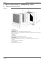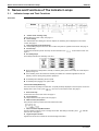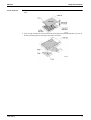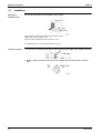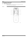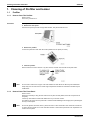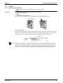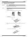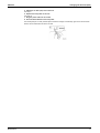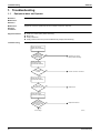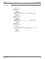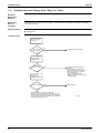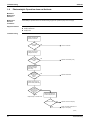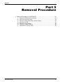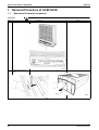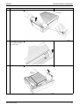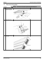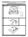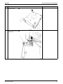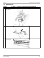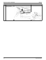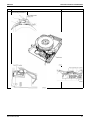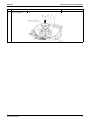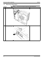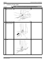
1
SiE00-06
Service
Manual
Air Cleaners
ACEF 3AVE
SiE00-06
Air Cleaners
ACEF 3AVE
1. Safety Cautions...................................................................................... iii
1.1 Cautions and Warnings ........................................................................... iii
1.2 Using Icons.............................................................................................. v
1.3 Using Icons List ....................................................................................... v
Part 1 Information .........................................................................1
1. General Description ................................................................................2
1.1 Introduction of Functions ......................................................................... 2
1.2 Accessories ............................................................................................. 3
1.3 Tips for Appropriate Use.......................................................................... 4
2. Names and Functions of The Operating Section ....................................5
2.1 Names and Functions of Parts ................................................................ 5
3. Names and Functions of The Indicator Lamps .......................................6
3.1 Indicator Lamps and Their Functions ...................................................... 6
Part 2 Field Setting .......................................................................7
1. Setup and Installation..............................................................................8
1.1 Setup ....................................................................................................... 8
1.2 Installation ............................................................................................. 10
2. Operation of The Unit............................................................................11
2.1 How to Operate The Unit....................................................................... 11
Part 3 Maintenance .....................................................................13
1. Cleaning of Prefilter and Ionizer............................................................14
1.1 Prefilter .................................................................................................. 14
1.2 Ionizer.................................................................................................... 15
2. Changing The Ion Filter (Roll) ...............................................................16
2.1 How to Change The Ion Filter (Roll) ...................................................... 16
Part 4 Troubleshooting ...............................................................19
1. Troubleshooting ....................................................................................20
1.1
1.2
1.3
1.4
Table of Contents
Equipment does not Operate................................................................. 20
Indicator does not Change from "Dirty" to "Clean." ............................... 22
Remote Controller Fails to Operate Equipment..................................... 23
Photocatalytic Operation does not Activate........................................... 24
i
SiE00-06
Part 5 Removal Procedure ..........................................................25
1. Removal Procedure of ACEF3AVE.......................................................26
1.1
1.2
1.3
1.4
1.5
1.6
1.7
Removal of External Accessories.......................................................... 26
Removal of Ionizing Wire....................................................................... 29
Removal of Electrical Parts (Inverter Lamp).......................................... 30
Removal of PCB .................................................................................... 33
Removal of Fan Motor ........................................................................... 36
Removal of Safety Switch...................................................................... 38
Installation of Power Cable.................................................................... 39
Part 6 Reference Data ................................................................41
1. Optional Accessories ............................................................................42
1.1 Specifications ........................................................................................ 42
2. Wiring Diagram .....................................................................................43
2.1 ACEF3AVE............................................................................................ 43
3. Parts List ...............................................................................................44
3.1 Parts Illustration..................................................................................... 44
3.2 Parts List................................................................................................ 45
Index
.............................................................................................i
Drawings & Flow Charts ...............................................................iii
ii
Table of Contents
SiE00-06
Safety Cautions
1. Safety Cautions
1.1
Cautions and Warnings
Read the following warnings and cautions BEFORE operating the system and use it correctly.
This manual classifies the precautions to the user into the following two categories.
Each mention important cautions on safety, so be sure to keep them.
WARNING
CAUTION
Failure to follow a warning is very likely to result in such grave consequences as death or serious
injury.
Failure to follow a caution may result in serious injury or property damage, and in certain
conditions, may result in a grave consequence.
The pictograms in the text show the following meanings.
Absolutely prohibited
Be sure to operate following instructions
Be sure to unplug the power cable
After reading, keep this manual in a place where the actual user can see it whenever necessary. And in
case of changing user, be sure to hand it to the new user.
Warning
Do not disassemble, service or
modify this equipment.
Unwarranted tempering can lead to fire
and/or malfunction.
Do not operate the equipment with
wet hands.
Otherwise electrical shock can result.
Use only 220-240 VAC 50 Hz power
supply.
Otherwise fire and electrical shock can
result.
Do not use the power cable if it is
damaged.
Using a damaged power cable is
extremely hazardous; if the power cord
becomes damaged, you must obtain a
replacement from the manufacturer or
from a properly-authorized service
agent.
Before changing filters, cleaning the
equipment or moving it, turn it OFF
and unplug the power cable.
Working with power ON can lead to fire
and/or electric shock.
Do not use the power cable if
damaged or loose in the socket.
Using the power cable in anything but
proper working condition can lead to
short-circuits and subsequently electric
shock and/or fire.
iii
Safety Cautions
SiE00-06
Caution
Do not use the equipment in a place
filled with oily smoke such as a
kitchen or in a place filled with
combustible gas, corrosive gas or
metal dust.
Otherwise fire and equipment
malfunction can result.
Do not use in humid places or places
which might be wet, such as
bathrooms.
Contact with
water can lead to
electric shock or
damage the
equipment.
Do not use the equipment near a
lighting fixture (keep a distance of at
least 1 m).
Lighting equipment
can cause poor
reception of remote
controller signals
and equipment
discoloration.
Do not use outdoors or where
exposed to direct sunlight.
Direct sunlight can
weaken remote
control signal
reception sensitivity
and discolor the
casing.
Do not use near to sources of heat
such as heaters.
Heat can discolor and deform the
casing.
Keep the unit and remote control
minimum 1 m from lighting, TVs,
radios, stereos and aerials.
This unit can disturb TV
pictures and generate
interference. Illumination can
weaken remote control signal
reception sensitivity and discolor the
casing.
Keep the equipment 10 cm or more
away from the wall when used on a
table.
Otherwise the wall can become dirty.
Do not use in the place of kitchen
fans or cooker hood fans.
Adverse coditions of use can shorten
service-life of the prefilter and ion filter,
as well as lead to equipment damage.
Prevent combustibles (hair sprays,
etc.), sparks and incense from being
drawn into the unit.
Such substances can cause fire.
Do not insert fingers or objects into
the openings of the suction and
discharge grilles.
Otherwise
electrical shock
and equipment
malfunction can
result.
When used in conjunction with a
humidifier, keep mist from being
directly drawn into the unit.
Mists can lead to electric shock and/or
equipment damage.
Do not block the intake or outlet.
Blocked openings can
reduce capacity (air will
not be cleaned throughout
the entire room) and/or
damage the equipment.
iv
SiE00-06
Safety Cautions
Caution
Do not place water containers such
as fish bowls and flower vases near
the equipment.
Water can cause electrical shock and
equipment malfunction when it enters
the equipment.
Do not wipe with benzene or thinner,
or spray with insecticide.
Such substances
can cause
cracking, electric
shock and/or fire.
If not using the unit for long periods
of time, unplug the power cable.
Dielectric breakdown can lead to
leakage current and subsequently
electric shock and/or fire.
Hold the plug to unplug the power
cord from the AC outlet. Do not pull
the cord to unplug.
Otherwise electrical
shock can result or
sparks may be
generated due to
shorting.
Do not operate the equipment without
the prefilter or roll filter.
Operating the equipment without the
filter can result in equipment
malfunction.
Do not sit or stand on the equipment.
Otherwise equipment malfunction can
result.
Do not position the equipment on its
side or tilt it during use.
Otherwise equipment
malfunction can
result.
Ventilate the room frequently when
used together with a heating device.
This product does not remove carbon
monoxide. Insufficient ventilation can
result in carbon monoxide poisoning.
1.2
Using Icons
Icons are used to attract the attention of the reader to specific information. The meaning of each icon is
described in the table below:
1.3
Using Icons List
Icon
Type of
Information
Description
Note
A “note” provides information that is not indispensable, but may
nevertheless be valuable to the reader, such as tips and tricks.
Caution
A “caution” is used when there is danger that the reader, through
incorrect manipulation, may damage equipment, loose data, get an
unexpected result or has to restart (part of) a procedure.
Warning
A “warning” is used when there is danger of personal injury.
Reference
A “reference” guides the reader to other places in this binder or in this
manual, where he/she will find additional information on a specific topic.
Note:
Caution
Warning
v
Safety Cautions
vi
SiE00-06
SiE00-06
Part 1
Information
1. General Description ................................................................................2
1.1 Introduction of Functions ......................................................................... 2
1.2 Accessories ............................................................................................. 3
1.3 Tips for Appropriate Use.......................................................................... 4
2. Names and Functions of The Operating Section ....................................5
2.1 Names and Functions of Parts ................................................................ 5
3. Names and Functions of The Indicator Lamps .......................................6
3.1 Indicator Lamps and Their Functions ...................................................... 6
Information
1
General Description
SiE00-06
1. General Description
1.1
Introduction of Functions
Dust Collection
Removes minute dust particles from room air.
Deodorizing
Effectively removes cigarette odors, raw garbage odors and body odors.
Harmful Gas
Removal
Breaks down automobile emissions (NOx) and new home odors.
Antiviral/
Disinfecting Effect
Removes and inactivates captured germs and viruses.
Convenient Ion
Filter Roll
Easy, economical and inexpensive filter replacement.
Designed for Quiet
Running
Users get the dual benefit of effective and quiet operation thanks to ion filtering.
Inverter Lamp
(Photocatalytic
cleaning).
The inverter lamp illuminates a photocatalyst which inactivates bacteria and viruses by high oxidation, thus
minimizing the possibility of contamination; It also decomposes components which generate offensive odor
in cigarette smoke, raw waste, exhaust gas (NOx), etc.
When used for the first time, the smell of the photocatalyst can be detected coming from the air outlet,
but there is nothing wrong with the equipment. As the unit runs, the odor will be decomposed and
eventually eliminated.
2
Information
SiE00-06
1.2
General Description
Accessories
Contents of
Accessories
Information
Check the following accessories have been included in the product package.
3
General Description
1.3
SiE00-06
Tips for Appropriate Use
To remove house dust, set the unit near to the floor.
To remove cigarette smoke, install the unit high on a wall.
Installing the air cleaner as shown below improves air circulation in the room.
While heating or coollng the room, air can be cleaned and temperature fluctuation minimized.
Set Operating Mode
as Needed.
Auto
Fan speed is controlled automatically depending on air quality. This mode ensures the most efficient
operation.
Manual (Fan speed)
Manual (Fan speed) - The unit runs independent of air quality. This mode is effective for regularly removing
orders not readily detected by the odor sensor or quickly eliminating house dust in room air.
Use the OFF timer appropriately to ensure the best room air quality when needed.
If the OFF timer is set when leaving the room, the air is clean when you return. When cleaning the room,
set fan speed to “High”.
4
Information
SiE00-06
Names and Functions of The Operating Section
2. Names and Functions of The Operating Section
2.1
Names and Functions of Parts
Illustration
A Front panel
B Ion filter (roll) case
Positively (+) charges minute dust particles not trapped by the prefilter.
C Ion filter roll
Working on the principle of electrostatic attraction, the negatively (-) charged filter catches and removes the
positively (+) charged dust.
D Air intake
E Inverter lamp
Activates the photocatalyst by illuminating it with light.
F Photocatalyst
Removes odors, bacteria and viruses when activated by the inverter lamp.
Do not subject the photocatalyst to excessive force. The inverter lamp located behind it will break.
G Prefilter
Removes comparatively large dust particles.
H Indicator lamps
Display operating status. See page 14.
Information
5
Names and Functions of The Indicator Lamps
SiE00-06
3. Names and Functions of The Indicator Lamps
3.1
Indicator Lamps and Their Functions
Illustration
A “Ionizer needs cleaning” lamp
Flashes when the ionizer is dirty. See page 11.
B Timer settings
The selected OFF timer setting is lit. As time elapses, the remaining time is displayed on the remote
control. See page 11.
C Pollen/Cigarette smoke mode lamps
The corresponding lamp is lit when the unit is in either the pollen or cigarette smoke mode. See page 11.
D Inverter lamp
Lit while the inverter lamp is ON. The lamp can be turned OFF from
on the remote control. See
page 11.
E Air Quality lamps
These lamps indicate how clean/dirty room air is.
Sharp fluctuations in temperature, humidity or odorless gases (carbon monoxide) can cause lamps to
light up and go out.
In the following cases, the lowest odor intensity is indicated for 2 minutes regardless of the true
intensity. There is nothing wrong with the equipment.
Immediately after reattaching the front panel.
Immediately after plugging in the power cable.
Constant Air Quality Monitoring
This unit monitors air quality even when OFF. Air quality is always displayed on the front panel. To turn the
display OFF in such a case, press
once more on the remote control. See page 11.
F Auto mode lamp
Lit when the unit is in the auto mode. See page 11.
G Fan speed lamp
The lamp under the set fan speed is lit. See page 11.
H Mode selector (OFF) button
Every time the button is pressed, the mode switches as follow.
J Time to cut filter lamp/Reset button
This lamp lights up when it is time to change the ion filter. After fitting a new filter, press
point pen, etc. See page 17.
K Signal reception window
Signals from the remote controller are received through this window.
6
with ball-
Information
SiE00-06
Part 2
Field Setting
1. Setup and Installation..............................................................................8
1.1 Setup ....................................................................................................... 8
1.2 Installation ............................................................................................. 10
2. Operation of The Unit............................................................................11
2.1 How to Operate The Unit....................................................................... 11
Field Setting
7
Setup and Installation
SiE00-06
1. Setup and Installation
1.1
Setup
1.1.1
How to Fit The Ion Filter
CAUTION
Always fit the prefilter and ion filter roll before use.
Use without filters can damage the equipment.
Remove The Front
Panel.
Hold the front panel by the left and right side handles, and pull forwards and out.
Remove The Ion
Filter (Roll) Case.
Hold the ion filter (roll) case by the left and right side handles, and lift upward and out.
8
Field Setting
SiE00-06
Fit The Filter Roll.
Setup and Installation
1. Face the ion filter (roll) case downwards as shown below and fit the filter roll in the cutouts for the filter
spool.
2. Unroll enough of the filter to cover the case and tuck the edges underneath the side tabs (x2). Then, fit
the slits on leading edge over the pags on both sides of the case.
Field Setting
9
Setup and Installation
1.2
SiE00-06
Installation
Selecting an
Installation Site.
The unit can be mounted on a flat surface such as a desk.
Select a shelf or floor that is sturdy enough to support the unit.
ACEF3AVE: The unit weighs 6.7 kg.
Select a location that blows air across the entire room.
For installation tips, see “Tips for appropriate use” page 4.
To Place on a Desk
1. Lie unit on its front and feed the power cable through the wide gutter on the bottom of the unit.
2. Slide the stand provided into the tracks on the bottom of the unit until you hear it click into
place.
10
Field Setting
SiE00-06
Operation of The Unit
2. Operation of The Unit
2.1
How to Operate The Unit
Before attempting to use the unit, plug the power cable into a single phase 220-240V socket.
The buttons and their functions are explained below.
Illustration
Field Setting
11
Operation of The Unit
Explanation
SiE00-06
A To turn the lamps ON/OFF
Pressing
turns the inverter lamp ON and OFF. Turn the lamp OFF if light from the front panel is
disturbing, for example at night. If left OFF, deodorizing and antiviral performance is reduced.
B To set fan speed manually
Every time
is pressed, fan speed changes as follows.
The fan starts at the last set fan speed.
When “Quiet” is selected, the fan turns slowly enough not to disturb people in their sleep.
C To remove pollen
Press
once to remove pollen from room air effectively. The unit will repeatedly switch between 5
minutes at normal speed and 5 minutes at low speed.
Press
again to turn the pollen mode OFF.
D To set the OFF timer
Every time
is pressed, the OFF timer setting changes as follows.
When the set time elapses, the unit shuts OFF automatically. The setting can be changed at any time even
while the unit is running.
E To start/stop the unit
The first time
is pressed, the unit starts up. The next time, it turns OFF.
F To set fan speed automatically
Press
. Fan speed is selected automatically - Quiet Low,
Normal, High - depending on air quality.
G To remove cigarette odors and smoke effectively
Press
once to remove cigarette odors and smoke from room air repidly. The unit will run for 5
minutes at high speed followed by 15 minutes at normal speed, and will then switch to auto fan speed
control.
Press
again to turn OFF the cigarette smoke mode.
H To turn OFF air quality lamps
Turn the air cleaner OFF before pressing this button when you want to turn OFF the lamps.
To operate the unit from the front panel
The unit can be operated from the front panel instead of the remote control. Pressing the
selects
operating mode and turns the unit OFF. See page 5.
If the unit malfunctions
If, during electrical storms or because of radio communications, the front panel lamps light irregularly, if the
unit cannot be operated from the remote controller or if some other problem occurs, unplug the power
cabel for a moment, then plug it back in and restart the unit.
12
Field Setting
SiE00-06
Part 3
Maintenance
1. Cleaning of Prefilter and Ionizer............................................................14
1.1 Prefilter .................................................................................................. 14
1.2 Ionizer.................................................................................................... 15
2. Changing The Ion Filter (Roll) ...............................................................16
2.1 How to Change The Ion Filter (Roll) ...................................................... 16
Maintenance
13
Cleaning of Prefilter and Ionizer
SiE00-06
1. Cleaning of Prefilter and Ionizer
1.1
Prefilter
1.1.1
How to Clean The Prefilter
When to clean
Once every 2 weeks or so.
Procedure
1. Stop the unit and remove the power cable from its socket.
2. Remove the front panel.
Hold the front panel by the left and right side handles, and pull forwards and out.
3. Remove the prefilter.
Lie the front panel face down and unhook the prefilter from the panel (x4 hooks).
4. Clean the prefilter.
Remove dirt with a vacuum cleaner or by other means, and then rinse the filter under plain water.
Note:
1.1.2
Do not rinse in water 50˚C or higher. Hot water will discolor and deform the filter beyond usable limits.
Keep away from fire and sources of heat. High temperatures will discolor and deform the filter beyond
usable limits.
How to Clean The Front Panel
When to clean
Whenever necessary if using the unit where the front panel is easily dirtied, clean the front panel more
frequently.
Vacuum up dust with the small nozzle attachment of your vacuum cleaner.
For stubborn dirt, clean the front panel with a neutral householddetergent.Thoroughly blot up all detergent
and dry in a dark place.
Note:
14
Do not use gasoline, benzene, thinner, polish, kerosene or other chemicals. Such chemicals can discolor
or deform the front panel. Do not use metal wire brushes or other hard implements. Such implements can
scratch the front panel.
Maintenance
SiE00-06
Cleaning of Prefilter and Ionizer
1.2
Ionizer
1.2.1
How to Clean The Ionizer
If
Procedure
(see page 6) on the front panel begins to flash, clean the ionizer.
1. Stop the unit and remove the power cabel from its socket.
2. Remove the front panel.
See page 8.
3. Remove the ion filter (roll) case.
Hold the ion filter (roll) case by the left and right side handles, and lift upwards and out.
4. Clean the ionizer.
Wipe the electrode plates and adjacent plastic parts with a soft cloth moistened with water or a wet tissue.
For stubborn dirt, detach the ion filter roll and wash with a neutral household detergent or soak and wipe
with a piece of cloth or soft brush. Thoroughly rinse off all detergent and dry in a dark place.
Note:
Maintenance
When cleaning the ionizer, always wear rubber gloves to prevent direct contact with the ionizing wires.
Be careful not to break the ionizing wires. If they should break, you can obtain replacements from your
supplier. If the unit is used with broken ionizing wires, the Clean Ionizer lamp will flash constantly. After
cleaning, dry the ionizer thoroughly. Usig the air cleaner with the ionizer still wet can damage the unit.
15
Changing The Ion Filter (Roll)
SiE00-06
2. Changing The Ion Filter (Roll)
2.1
How to Change The Ion Filter (Roll)
Explanation
If
(see page 5 on the front panel lightsup, change the ion filter. When the ion filter needs to be
changed will depend on the conditions of use.
If the unit is used where air is dirty, the ion filter will need changing more frequently. When using for 7 hours
per day in auto mode, change the filter every 8 months.
Procedure
1. Stop the unit and remove the power cable from its socket.
2. Remove the front panel.
See page 8.
3. Remove the ion filter (roll) case.
Hold the ion filter (roll) case by the left and right side handles, and lift upwards and out.
4. Cut the ion filter.
A Pull the ion filter off the 2 pegs on the case.
B Unroll the ion filter until the slits in the leading edge of the next filter sheet can be fitted over the pegs on
the case.
C
16
Tear the old filter sheet off at the perforated line.
Maintenance
SiE00-06
Changing The Ion Filter (Roll)
5. Attach the ion filter (roll) case to the unit.
See step 3.
6. Replace the front panel on the unit.
See page 8.
7. Plug the power cable into its socket.
8. Press the Reset button on the front panel.
Use a ball-point pen or other pointed object. Check the Change Ion Filter lamp goes out A short acoustic
buzzer can be heard when the sensor is reset.
Maintenance
17
Changing The Ion Filter (Roll)
18
SiE00-06
Maintenance
SiE00-06
Part 4
Troubleshooting
1. Troubleshooting ....................................................................................20
1.1
1.2
1.3
1.4
Troubleshooting
Equipment does not Operate................................................................. 20
Indicator does not Change from "Dirty" to "Clean." ............................... 22
Remote Controller Fails to Operate Equipment..................................... 23
Photocatalytic Operation does not Activate........................................... 24
19
Troubleshooting
SiE00-06
1. Troubleshooting
1.1
Equipment does not Operate.
Method of
Malfunction
Detection
Malfunction
Decision
Conditions
Equipment cannot be operated by remote controller or switch on main unit.
Supposed Causes
Faulty door switch (safety switch assembly)
Blown fuse
Faulty transformer
Faulty printed circuit board (control PCB assembly, display PCB assembly)
Troubleshooting
Check door switch
(safety switch assembly).
Does
equipment fail
to operate when
short-circuited?
NO
Defective door switch
(safety switch assembly)
YES
Check connector
connection of A1P
control PCB assembly.
Is connection
normal?
NO
Correct connector connection.
YES
Check fuse for A1P
control PCB assembly.
Is there
continuity in fuse?
NO
Replace fuse.
YES
Check transformer
secondary voltage (X3A).
Is voltage
higher than 12.5
VDC and lower than
23 VDC?
NO
Replace transformer.
YES
To next page
20
(EF001)
Troubleshooting
SiE00-06
Troubleshooting
Troubleshooting
From previous page
Check 12-volt power
supply (between X12A
(1) and (4)).
Is voltage
higher than 11.5
VDC and lower than
12.5 VDC?
NO
Replace control PCB
(control PCB assembly).
YES
Check 5-volt power
supply (between X9A (1)
and (4)).
Is voltage
NO
higher than 4.5
VDC and lower than
5.5 VDC?
Replace control PCB
(control PCB assembly).
YES
Check connector
connection of A2P
display PCB assembly.
Is connection
normal?
NO
Correct connector connection.
YES
Replace display PCB
(Display PCB assembly)
Troubleshooting
(EF002)
21
Troubleshooting
1.2
SiE00-06
Indicator does not Change from "Dirty" to "Clean."
Method of
Malfunction
Detection
Malfunction
Decision
Conditions
Air contamination indicator does not change to "clean" even when equipment is operated in ventilated
room for a whole day.
Supposed Causes
Faulty harness
Faulty sensor
Troubleshooting
Check connector
connection.
Are X14A and
X101A normal?
NO
Correct connector connection
YES
Check humidity at
installation site.
Is humidity
80% RH or lower?
NO
YES
Check room
condition after
equipment operation.
Is room air clean?
NO
This does not denote equipment
malfunction.
Built-in high-performance sensor
detects moisture in room air, and
equipment continues to operate at
Low, Normal or High.
•Change installation location.
•Unplug power cord, reconnect, then
restart equipment.
Replace sensor
YES
This does not denote equipment malfunction.
When the room is too large for the unit's capacity, the
indicator may still indicate "dirty" after smoke is removed.
This is caused by the high-performance sensor detecting
slight contamination in the room.
22
(EF003)
Troubleshooting
SiE00-06
1.3
Troubleshooting
Remote Controller Fails to Operate Equipment.
Method of
Malfunction
Detection
Malfunction
Decision
Conditions
Switches on main unit work properly, but remote controller fails to operate equipment.
Supposed Causes
Noise generated by fluorescent lamps
Faulty remote controller
Faulty PCB
Troubleshooting
Check batteries in
remote controller.
Does
problem
remain after new
batteries are
installed?
NO
Battery consumption
YES
Check location
conditions.
Does
different
remote controller
fail to operate
equipment?
NO
Replace remote controller
YES
Check location
conditions
Are there
fluorescent lamps
nearby?
NO
Replace display PCB
YES
Change installation location by
referring to operation manual.
Troubleshooting
(EF004)
23
Troubleshooting
1.4
SiE00-06
Photocatalytic Operation does not Activate.
Method of
Malfunction
Detection
Malfunction
Decision
Conditions
Photocatalytic operation does not activate during equipment operation (lamp does not light).
Supposed Causes
Faulty lamp
Faulty transformer
Faulty PCB
Troubleshooting
Check connector and
harness connection.
Is connection
normal?
NO
Correct connection
YES
Check power supply
voltage (A1P-X2A).
Is voltage
between 220 to 240
VAC?
NO
Replace control PCB (A1P)
YES
Check transformer
secondary voltage
(A1P-X3A).
Is voltage
higher than 12.5
VDC and lower
than 23
VDC?
NO
Replace transformer
YES
Check power supply of
inverter PCB. (A4P-CN1)
Is voltage
higher than 11.5
VDC and lower
than 12.5
VDC?
NO
YES
Check power supply of
control PCB (A1P) X7A
Replace lamp or inverter PCB.
DC11.5~12.5V ?
YES
NO
Replace control P.C.B (A1P)
Faulty connection between X7A
(A1P) to CN1 (A4P)
(EF005)
24
Troubleshooting
SiE00-06
Part 5
Removal Procedure
1. Removal Procedure of ACEF3AVE.......................................................26
1.1
1.2
1.3
1.4
1.5
1.6
1.7
Removal Procedure
Removal of External Accessories.......................................................... 26
Removal of Ionizing Wire....................................................................... 29
Removal of Electrical Parts (Inverter Lamp).......................................... 30
Removal of PCB .................................................................................... 33
Removal of Fan Motor ........................................................................... 36
Removal of Safety Switch...................................................................... 38
Installation of Power Cable.................................................................... 39
25
Removal Procedure of ACEF3AVE
SiE00-06
1. Removal Procedure of ACEF3AVE
1.1
Removal of External Accessories
Procedure
Step
Be sure to turn off all power supplies before disassembling work
Procedure
1
External appearance
2
Tilt main body to remove
stand.
26
Warning
Points
Removal Procedure
SiE00-06
Step
Removal Procedure of ACEF3AVE
Procedure
3
Remove front panel
4
Disengage hooks located at
four of corners of the filter to
remove prefilter located at
rear side of panel.
5
Remove ion-roll filter case
Removal Procedure
Points
27
Removal Procedure of ACEF3AVE
Step
6
28
SiE00-06
Procedure
Points
Main components
Removal Procedure
SiE00-06
1.2
Removal Procedure of ACEF3AVE
Removal of Ionizing Wire
Procedure
Step
Warning
Be sure to turn off all power supplies before disassembling work
Procedure
1
Push the hook using (-)
screw driver to remove
ionizing wire fixing plate.
2
Remove ionizing wire
3
Peel off sealing strips at top
of main body.
Removal Procedure
Points
29
Removal Procedure of ACEF3AVE
1.3
Removal of Electrical Parts (Inverter Lamp)
Procedure
Step
Warning
Be sure to turn off all power supplies before disassembling work
Procedure
1
Remove eight screws.
Remove display box before
remove a screw located at
bottom right of main body
front side.
2
Remove catalyst filter
retainer.
3
Remove catalyst filter.
30
SiE00-06
Points
Removal Procedure
SiE00-06
Step
Removal Procedure of ACEF3AVE
Procedure
4
Turn main body over, then
remove back panel.
5
Disconnect CN2 connector
located at bottom left of main
body rear side.
Removal Procedure
Points
31
Removal Procedure of ACEF3AVE
Step
Procedure
6
Turn front side of main body
up, then remove inverter
lamps from lamp sockets.
7
Pull out connector for
inverter lamp.
32
SiE00-06
Points
Removal Procedure
SiE00-06
1.4
Removal Procedure of ACEF3AVE
Removal of PCB
Procedure
Step
Warning
Be sure to turn off all power supplies before disassembling work
Procedure
1
Dismount a screw located at
bottom right of main body to
remove display box.
2
Disengage 10 hooks.
3
Disengage the hooks to
remove display PCB.
Removal Procedure
Points
33
Removal Procedure of ACEF3AVE
Step
4
34
SiE00-06
Procedure
Points
Be careful not to lose
protective sheet when
removing gas sensor PCB.
Removal Procedure
SiE00-06
Step
5
Removal Procedure of ACEF3AVE
Procedure
Points
Location of PCBs is shown
in the following illustrations.
Removal Procedure
35
Removal Procedure of ACEF3AVE
1.5
Removal of Fan Motor
Procedure
Step
1
SiE00-06
Warning
Be sure to turn off all power supplies before disassembling work
Procedure
Points
Remove back panel to
remove fan securing nut.
Caution
When reassembling fan, match the Dcut direction of fan and shaft.
2
Disconnect connector.
Caution
When installing motor mounting plate,
put the surface with protrusions up
side.
36
Removal Procedure
SiE00-06
Step
3
Removal Procedure of ACEF3AVE
Procedure
Points
Remove three screws on
motor mounting plate.
Removal Procedure
37
Removal Procedure of ACEF3AVE
1.6
Removal of Safety Switch
Procedure
Step
Warning
Be sure to turn off all power supplies before disassembling work
Procedure
1
Remove door switch cover
2
To remove safety switch,
push it out from back side.
38
SiE00-06
Points
Removal Procedure
SiE00-06
1.7
Removal Procedure of ACEF3AVE
Installation of Power Cable
Procedure
Step
Warning
Be sure to turn off all power supplies before disassembling work
Procedure
1
Insert cord bushing to the
hole at front side of main
body.
2
Adjust the bushing position
in order to insert back panel
into groove of cord bushing
before install back panel.
3
Installation of power cable is
complete.
Removal Procedure
Points
39
Removal Procedure of ACEF3AVE
40
SiE00-06
Removal Procedure
SiE00-06
Part 6
Reference Data
1. Optional Accessories ............................................................................42
1.1 Specifications ........................................................................................ 42
2. Wiring Diagram .....................................................................................43
2.1 ACEF3AVE............................................................................................ 43
3. Parts List ...............................................................................................44
3.1 Parts Illustration..................................................................................... 44
3.2 Parts List................................................................................................ 45
Reference Data
41
Optional Accessories
SiE00-06
1. Optional Accessories
1.1
Specifications
Unit
Model
ACEF3AVE
Required Power Supply
220-240/220V 50/60Hz
Outer Dimensions
395x462x180 (Without Stand)
395x479x184 (When Installed on Stand)
Rated Power Consumption (W)
43/47
Air Blow Rate (m³/min)
High Speed 3.0
Normal Speed 2.0 Quiet 0.6
Low Speed 1.4
Applicable Room Area
~30m²
Weight
6.7
Replacement Ion Filter
KAC 12B
Screw
Location
42
Part Name
Designation
ACEF3AVE
Motor Mounting Plate
Tapping Screw + Truss Head
(2)M4X16N
3
Printed Circuit Bord Assy (For Power
Supply)
Pan Head Tapping
(2) M4X16
1
Rear Panel
Tapping Screw + Truss Head
(2)M4X16N
5
Printed Circuit Bord Assy (For Power
Supply) -Sensor Tunnel
Pan Head Tapping
(2) M4X16
1
Power Transformer-Sensor Tunnel
Tapping Screw + Truss Head
(2)M4X16N
1
Indicate Box Assy
Tapping Screw + Truss Head
(2)M4X16CHROMEPLATED
1
Inverter
Tapping Screw + Pan Head
(2)M3X12N
2
Contact Plate
Tapping Screw + Truss Head
(2)M4X16N
1
High Voltage Contact
Tapping Screw + Truss Head
(2)M4X16N
1
Power Transformer
Tapping Screw + Truss Head
(2)M4X16N
2
Guide For Catalyst
Tapping Screw + Truss Head
(2)M4X12CHROMEPLATED
2
Fan
Nut
M6
1
Reference Data
SiE00-06
Wiring Diagram
2. Wiring Diagram
2.1
ACEF3AVE
Reference Data
43
Parts List
SiE00-06
3. Parts List
3.1
Parts Illustration
ACEF3AVE
44
Reference Data
SiE00-06
3.2
Parts List
Parts List
ACEF3AVE
No.
Index
Parts No.
Parts Name
Drwg. No.
Parts Model
Specification
Q’ty/Unit
ACEF3AVE
C1
0948119
SIROCCO FAN ASSY
3P003606-1
1071276
IONIZER AND ROLLCASE ASSY
3P010121-3
1
E11-1
1069336
ION ROLL CASETTE CASE
1P009666-2
1
E11-2
1021194
IONIZER WIRE HOLD PLATE
3P009501-1
E11-3
1021202
ELECTRODE PLATE
3P006853-1
1
E11-4
1041066
IONIZER WIRE ASSY
4PH11835-2
3
E11-5
1021219
IONIZER WIRE MOUNTING PLATE
3P008923-1
1
E11-6
1021226
EARTH PLATE
4P010468-1
1
E11-7
1083301
OPERATION NAME PLATE
4P031138-1
55Kg/REAM
WHITE
1
t0.125
3
COLOR GREEN
GRAY
1
E11
A
E11-8
E12
A
E12-1
E12-2
1069343
GUARD
4P028308-1
0948809
CONTACTOR ASSY
4P010108-1
1021257
HIGH VOLTAG CONTACT PLATE
FRAME
3P009404-1
Wiring
Symbol
1
GREEN GRAY
1
1
0948816
CONTACTOR
4P010467-1
1
E13
A
0948816
CONTACTOR
4P010467-1
1
E14
A
1179923
SAFETY SWITCH (RED)
4P040549-2
1
E15
A
1179930
SAFETY SWITCH (BLACK)
4P040548-2
1
E16
A
1041718
FILTER
3P026231-1
1
E19
A
1063422
SINGLE PHASE AC FAN MOTOR
3P025867-1
E38
A
1176777
PCB ASSY(CONTROL)
2P057777-1
4P 18W 230V
EH0009
1
M1F
1
A1P
E39
A
0963550
INVERTER PCB ASS’Y
3P005968-1
EH9712
1
A4P
E40
A
1071308
PCB ASSY(HIGH VOLTAGE
POWER)
3P025771-1
HV9801
1
A5P
E41
B
1071238
LOW FREQUENCY
TRANSFORMER
3EA74047-1
E43
A
1
1179947
LAMP ASSY
3P044833-1
E44
1179954
POWER CABLE
3P057561-1
E45
1083325
WIRE HARNESS(FOR FAN
MOTOR)
4P028383-1
1
F1
F1-1
F1-2
B
F2
F3
1
color:FINMOST
1
FRONT PANEL ASSY
3P025604-11
1
1083224
FRONT PANEL ASSY
3P026935-2
1
1069350
LIGHT MONITER
3P026218-1
1
0952738
REAR PANEL
1P007743-2
1
1
0947572
PRE FILTER
1P009670-1
F4
1071151
INSIDE FRAME
1P009062-2
1
F5
0948289
WIRE CLAMP
3P009439-1
1
1
F6
A
0948272
PUSH BUTTON
3P009078-1
F7
0952745
DISCH.GRILLE (3)
3P008427-2
1
F8
1181988
INDICATE BOX ASSY
3P026235-5
1
F8-1
1069312
DISPLAY BOX FRONT
1P009628-2
1
F8-2
1069329
DISPLAY BOX
2P009024-1
1
PCB ASSY(FOR INDICATION)
2P058358-1
F8-3
B
A
1176760
F8-3-1
EH0008
1
INFRARED RECEIVER UNIT LABEL 4EA81002-3
A
1181933
GAS SENSOR PCB ASSY
3P041368-2
1
F8-7
B
1021365
PROTECTION SHEET
4P013881-1
1
F9
B
0947750
SENSOR TUNNEL
2P008539-1
1
F10
B
1122996
SWITCH COVER
3P026435-1
MANUFACTURER LABEL
4P055464-1
FRDSTED
SILVER t0.05
1
t0.07
1
1181940
BLAND NAME LABEL
4P039562-1
F26
0948203
MOTOR MOUNTING PLATE
3P006693-1
1
F27
1042759
STAND
1P026219-2
1
F37
1069374
GUIDE FOR CATALYST
3P026234-1
A
1181995
K4
K5
K6
A
1176784
Reference Data
A3P
1
F23
K3
A2P
1
F8-6
F22
Notes
COLOR:GREEN
GRAY
1
ROLL FILTER ASSY
4P014090-4
1
ACCESSORY KIT
4P054569-1
1
OPERATION MANUAL
3P026236-17
1
WIRELESS REMOTE
CONTROLLER ASSY
3P040927-1
1
45
Parts List
46
SiE00-06
Reference Data
SiE00-06
Index
A
R
Accessories ..............................................................3
Air Blow Rate (m³/min) ...........................................42
Antiviral/Disinfecting Effect .......................................2
Applicable Room Area ...........................................42
Rated Power Consumption (W) ............................ 42
Remote Controller Fails to Operate Equipment. ... 23
Removal of Electrical Parts (Inverter Lamp) ......... 30
Removal of External Accessories ......................... 26
Removal of Fan Motor ........................................... 36
Removal of Ionizing Wire ...................................... 29
Removal of PCB .................................................... 33
Removal of Safety Switch ..................................... 38
Removal Procedure .............................................. 25
Remove The Front Panel. ....................................... 8
Remove The Ion Filter (Roll) Case. ......................... 8
Replacement Ion Filter .......................................... 42
Required Power Supply ........................................ 42
C
Cautions and Warnings ........................................... iii
Changing The Ion Filter (Roll) ................................16
Cleaning of Prefilter and Ionizer .............................14
Convenient Ion Filter Roll .........................................2
D
Deodorizing ..............................................................2
Designed for Quiet Running .....................................2
Dust Collection .........................................................2
S
Equipment does not Operate. ................................20
Selecting an Installation Site. ................................ 10
Set Operating Mode as Needed. ............................. 4
Setup and Installation .............................................. 8
F
T
Fit The Filter Roll. .....................................................9
Tips for Appropriate Use ......................................... 4
To Place on a Desk ............................................... 10
Troubleshooting .................................................... 20
E
H
Harmful Gas Removal ..............................................2
How to Change The Ion Filter (Roll) .......................16
How to Clean The Front Panel ...............................14
How to Clean The Ionizer .......................................15
How to Clean The Prefilter .....................................14
How to Fit The Ion Filter ...........................................8
How to Operate The Unit .......................................11
W
Weight ................................................................... 42
Wiring Diagram
ACEF3AVE ..................................................... 43
I
Indicator does not Change from "Dirty"
to "Clean." .......................................................22
Indicator Lamps and Their Functions .......................6
Installation of Power Cable ....................................39
Introduction of Functions ..........................................2
Inverter Lamp (Photocatalytic cleaning). ..................2
Ionizer ....................................................................15
N
Names and Functions of Parts .................................5
O
Optional Accessories .............................................42
Outer Dimensions ..................................................42
P
Parts Illustration .....................................................44
Parts List ..........................................................44, 45
Photocatalytic Operation does not Activate. ..........24
Prefilter ...................................................................14
Index
i
SiE00-06
ii
Index
SiE00-06
Drawings & Flow Charts
A
I
Air Quality lamps ......................................................6
Before changing filters, cleaning the equipment
or moving it, turn it OFF
and unplug the power cable. ............................ iii
If not using the unit for long periods of time,
unplug the power cable. ....................................v
Indicator does not Change
from "Dirty" to "Clean." ................................... 22
Indicator Lamps and Their Functions ...................... 6
Installation of Power Cable ................................... 39
C
K
Clean the ionizer. ...................................................15
Clean the prefilter. ..................................................14
Contents of Accessories ..........................................3
Cut the ion filter. .....................................................16
Keep the equipment 10 cm or more away
from the wall when used on a table. ................iv
B
M
Mode selector (OFF) button .................................... 6
D
Do not block the intake or outlet. ............................ iv
Do not disassemble, service
or modify this equipment. ................................. iii
Do not insert fingers or objects into the openings
of the suction and discharge grilles. ................. iv
Do not operate the equipment with wet hands. ....... iii
Do not place water containers such as fish bowls
and flower vases near the equipment. ..............v
Do not position the equipment on its side
or tilt it during use. .............................................v
Do not use in humid places or places
which might be wet, such as bathrooms. ......... iv
Do not use in the place of kitchen fans
or cooker hood fans. ........................................ iv
Do not use near to sources of heat
such as heaters. ............................................... iv
Do not use outdoors or where exposed
to direct sunlight. .............................................. iv
Do not use the equipment
in a place filled with oily smoke ........................ iv
Do not use the equipment near a lighting fixture .... iv
Do not use the power cable if damaged
or loose in the socket. ...................................... iii
Do not use the power cable if it is damaged. .......... iii
Do not wipe with benzene or thinner,
or spray with insecticide. ...................................v
N
Names and Functions of Parts ................................ 5
P
Parts Illustration .................................................... 44
Photocatalytic Operation does not Activate. ......... 24
Press the Reset button on the front panel. ............ 17
Prevent combustibles (hair sprays, etc.), sparks
and incense from being drawn into the unit. ....iv
R
Remote Controller Fails to Operate Equipment. ... 23
Removal of Electrical Parts (Inverter Lamp) ......... 30
Removal of External Accessories ......................... 26
Removal of Fan Motor ........................................... 36
Removal of Ionizing Wire ...................................... 29
Removal of PCB .................................................... 33
Removal of Safety Switch ..................................... 38
Remove The Front Panel. ....................................... 8
Remove the front panel. ........................................ 14
Remove The Ion Filter (Roll) Case. ......................... 8
Remove the ion filter (roll) case. ..................... 15, 16
Remove the prefilter. ............................................. 14
S
Selecting an Installation Site. ................................ 10
E
T
Equipment does not Operate. ................................20
Fit The Filter Roll. .....................................................9
Tips for Appropriate Use ......................................... 4
To Place on a Desk ............................................... 10
To set fan speed manually .................................... 12
To set the OFF timer ............................................. 12
H
U
Hold the plug to unplug the power cord from
the AC outlet. Do not pull the cord to unplug. ...v
How to Operate The Unit .......................................11
Use only 220-240 VAC 50 Hz power supply. .......... iii
F
V
Ventilate the room frequently
when used together with a heating device. .......v
Drawings & Flow Charts
iii
SiE00-06
W
Wiring Diagram
ACEF3AVE ......................................................43
iv
Drawings & Flow Charts
ISO14001 assures an effective environmental management
system in order to help protect human health and the
environment from the potential impact of our activities,
products and services and to assist in maintaining and
improving the quality of the environment.
Daikin Europe NV is approved by LRQA for its Quality
Management System in accordance with the ISO9001
standard. ISO9001 pertains to quality assurance
regarding design, development, manufacturing as well as
to services related to the product.
DAIKIN PRODUCTS ARE DISTRIBUTED BY:
Specifications subject to change without notice.
Zandvoordestraat 300
B-8400 Oostende
Belgium
Head Office:
Umeda Center Bldg., 4-12
Nakazaki-Nishi
2-chome, Kita-ku, Osaka
530 Japan
Printed in Belgium/SiE00-06
Daikin units comply with the European regulations that
guarantee the safety of the product.