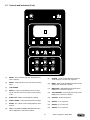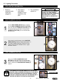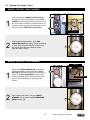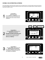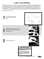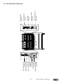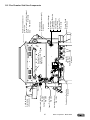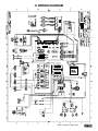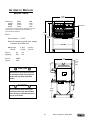
1
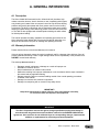
AUTOMATIC
FOOD SERVICE
EQUIPMENT
AUTOMATIC GAS BROILER
MODEL 9025 (CCSI CONTROL)
OWNERS MANUAL
IMPORTANT: RETAIN THIS MANUAL IN A SAFE PLACE
FOR FUTURE REFERENCE.
FOR YOUR SAFETY:
Do not store or use gasoline or other flammable vapors or liquids in
the vicinity of this or any other appliance.
WARNING: Improper installation, adjustment, alteration, maintenance
can cause property damage, injury, or death. Read the installation,
operating and maintenance instructions thoroughly before installing
or servicing this equipment.
Broiler area must be kept free of combustible materials, and the flow of combustion and ventilation air
must not be obstructed. Operating personnel must not perform any maintenance or repair functions.
Contact your Nieco Authorized Dealer.
In a prominent location, post instructions to be followed in the event the user smells gas. This information shall be obtained by consulting your local gas supplier.
TABLE OF CONTENTS
A. General Information . . . . . . . . . . . .
A.1 Description . . . . . . . . . . . . . .
A.2 Warranty Information . . . . . .
A.3 Service/Technical Assistance
A.4 Safety Information . . . . . . . .
.
.
.
.
.
.
.
.
.
.
.
.
.
.
.
.
.
.
.
.
.
.
.
.
.
.
.
.
.
.
.
.
.
.
.
.
.
.
.
.
.
.
.
.
.
.
.
.
.
.
.
.
.
.
.
.
.
.
.
.
.
.
.
.
.
.
.
.
.
.
.
.
.
.
.
.
.
.
.
.
.
.
.
.
.
.
.
.
.
.
.
.
.
.
.
.
.
.
.
.
.
.
.
.
.
.
.
.
.
.
.
.
.
.
.
.
.
.
.
.
.
.
.
.
.
.
.
.
.
.
.
.
.
.
.
.
.
.
.
.
.3
.3
.3
.4
.4
B. Machine Installation . . . . . . . . . . . .
B.1 Pre-Installation . . . . . . . . . . .
B.2 Mounting . . . . . . . . . . . . . . .
B.3 Leveling . . . . . . . . . . . . . . . .
B.4 Hood Requirements . . . . . . .
B.5 Clearance . . . . . . . . . . . . . .
B.6 Gas Connection . . . . . . . . . .
B.7 Flexible Gas Line Installation
B.8 Restraining Device . . . . . . . .
B.9 Electrical Connection . . . . . .
B.10 Pre-Operation Check . . . . . .
.
.
.
.
.
.
.
.
.
.
.
.
.
.
.
.
.
.
.
.
.
.
.
.
.
.
.
.
.
.
.
.
.
.
.
.
.
.
.
.
.
.
.
.
.
.
.
.
.
.
.
.
.
.
.
.
.
.
.
.
.
.
.
.
.
.
.
.
.
.
.
.
.
.
.
.
.
.
.
.
.
.
.
.
.
.
.
.
.
.
.
.
.
.
.
.
.
.
.
.
.
.
.
.
.
.
.
.
.
.
.
.
.
.
.
.
.
.
.
.
.
.
.
.
.
.
.
.
.
.
.
.
.
.
.
.
.
.
.
.
.
.
.
.
.
.
.
.
.
.
.
.
.
.
.
.
.
.
.
.
.
.
.
.
.
.
.
.
.
.
.
.
.
.
.
.
.
.
.
.
.
.
.
.
.
.
.
.
.
.
.
.
.
.
.
.
.
.
.
.
.
.
.
.
.
.
.
.
.
.
.
.
.
.
.
.
.
.
.
.
.
.
.
.
.
.
.
.
.
.
.
.
.
.
.
.
.
.
.
.
.
.
.
.
.
.
.
.
.
.
.
.
.
.
.
.
.
.
.
.
.
.
.
.
.
.
.
.
.
.
.
.
.
.
.
.
.
.
.
.
.
.
.
.
.
.
.
.
.
.
.
.
.
.
.
.
.
.
.
.
.
.
.
.
.
.
.
.
.6
.6
.6
.6
.7
.7
.8
.8
.9
.9
.9
C. Operation . . . . . . . . . . . . . . . . . . . . . . . .
C.1 Controls and Indicators . . . . . . . .
C.2 Step-by-Step Lighting Procedure
C.3 Shutdown Procedure . . . . . . . . .
C.4 Control Operation . . . . . . . . . . . .
.
.
.
.
.
.
.
.
.
.
.
.
.
.
.
.
.
.
.
.
.
.
.
.
.
.
.
.
.
.
.
.
.
.
.
.
.
.
.
.
.
.
.
.
.
.
.
.
.
.
.
.
.
.
.
.
.
.
.
.
.
.
.
.
.
.
.
.
.
.
.
.
.
.
.
.
.
.
.
.
.
.
.
.
.
.
.
.
.
.
.
.
.
.
.
.
.
.
.
.
.
.
.
.
.
.
.
.
.
.
.
.
.
.
.
.
.
.
.
.
.10
.10
.12
.14
.15
D. Assembly/Disassembly and Cleaning . . . . . . . . . . . . . . . . . . . . . . . . . .20
E. Troubleshooting Guide . . . . . . . . . . . . . . . . . . . . . . . . . . . . . . . . . . . . . .39
F. Broil Chain Tension & Link Removal . . . . . . . . . . . . . . . . . . . . . . . . . . .42
G. Parts and Locations . . . . . . . . . . . . . . . . . . .
G.1 Main Chamber Removable Parts . . . .
G.2 Flex Chamber Removable Parts . . . . .
G.3 Feed End View Components . . . . . . . .
G.4 Main Chamber Side View Components
G.5 Flex Chamber Side View Components
G.6 Model 9025 Parts List . . . . . . . . . . . . .
.
.
.
.
.
.
.
.
.
.
.
.
.
.
.
.
.
.
.
.
.
.
.
.
.
.
.
.
.
.
.
.
.
.
.
.
.
.
.
.
.
.
.
.
.
.
.
.
.
.
.
.
.
.
.
.
.
.
.
.
.
.
.
.
.
.
.
.
.
.
.
.
.
.
.
.
.
.
.
.
.
.
.
.
.
.
.
.
.
.
.
.
.
.
.
.
.
.
.
.
.
.
.
.
.
.
.
.
.
.
.
.
.
.
.
.
.
.
.
.
.
.
.
.
.
.
.
.
.
.
.
.
.
.
.
.
.
.
.
.
.43
.43
.44
.45
.46
.47
.48
H. Wiring Diagram . . . . . . . . . . . . . . . . . . . . . . . . . . . . . . . . . . . . . . . . . . . .49
I. Specifications . . . . . . . . . . . . . . . . . . . . . . . . . . . . . . . . . . . . . . . . . . . . .50
J. Warranty Information . . . . . . . . . . . . . . . . . . . . . . . . . . . . . . . . . . . . . . .52
2
Nieco Corporation - Model 9025
A. GENERAL INFORMATION
A.1 Description
The Nieco® Model 9025 automatic broiler, utilizes dual broil chambers, high
release convection burners, electric elements, a new, simplified ignition system,
easy cleaning and a state-of-the-art computer control to help eliminate broiling
problems and provide the operator with even greater control over the broiling
environment. The 9025 is return-flow, with an automatic product return system,
allowing for space savings, while delivering product to the feed end of the broiler. The 9025 is also equipped with a heated product holding unit which allows
for limited product holding.
This manual provides the safety, installation and operating procedures for the
Nieco Automatic Broiler Model 9025. We recommend that all information contained in this manual be read prior to installing and operating the broiler.
A.2 Warranty Information
Please read the full text of the limited Warranty in this manual.
If the unit arrives damaged, contact the carrier immediately and file a damage claim with them. Save all
packing materials when filing a claim. Freight damage claims are the responsibility of the purchaser and
ARE NOT covered under warranty.
The warranty does not extend to:
•
•
•
•
•
•
•
Damages caused in shipment or damage as a result of improper use.
Installation of electrical service.
Normal maintenance as outlined in this manual.
Malfunction resulting from improper maintenance not in accordance with the steps contained in
this manual and any applicable training.
Damage caused by abuse or careless handling outside of the normal operating procedures
contained in this manual.
Damage from moisture into electrical components.
Damage from tampering with or removal of any safety device.
IMPORTANT!
Keep these instructions for future reference. If the unit changes ownership,
be sure this manual accompanies the equipment.
IMPORTANT
The Nieco Corporation reserves the right to change specifications and product design in
accordance with the general terms and conditions outlined in the BURGER KING®/Vendor
agreement. .Such revisions do not entitle the buyer to corresponding changes, improvements,
additions or replacements for previously purchased equipment.
3
Nieco Corporation - Model 9025
A.3 Service/Technical Assistance
If you experience any problems with the installation or operation of your broiler, contact your local
Authorized Nieco Distributor.
Fill in the information bellow and have it handy when calling your authorized service agency for assistance.
The serial number is on the broiler rating plate on the side of the unit.
Purchased from:
Date of Purchase:
Model No.:
Serial No.:
For the name of your local Authorized Nieco Distributor, please call (800) 821-2141.
Use only genuine Nieco replacement parts in your broiler. Use of replacement parts other than those supplied by Authorized Nieco Distributors and Service Agencies will void the warranty and may significantly
alter the performance of your broiler. Nieco and the Burger King Corporation have worked together to create a set of standards for broiler performance, food quality and food safety. The use of non-Nieco parts is
capable of affecting these criteria, and may affect broiler performance, parts longevity and food safety. Your
local Authorized Nieco Distributor and Service Agent has been factory trained and has a complete supply
of parts for your Nieco Automatic Broiler.
You may contact the factory direct at (707) 284-7100 if you have trouble locating your local Nieco
Distributor.
A.4 Important Safety Information
Throughout this manual, you will find the following safety words and symbols that signify important safety
issues with regards to operating or maintaining the equipment:
WARNING
WARNING
GENERAL WARNING. Indicates
information important to the proper
operation of the equipment. Failure
to observe may result in damage to
the equipment and/or severe bodily
injury or death.
ELECTRICAL WARNING. Indicates
information relating to possible
shock hazard. Failure to observe
may result in damage to the equipment and/or severe bodily injury or
death.
CAUTION
WARNING
GENERAL CAUTION. Indicates
information important to the proper
operation of the equipment. Failure
to observe may result in damage to
the equipment.
HOT SURFACE WARNING. Indicates
information important to the handling of equipment and parts.
Failure to observe caution could
result in personal injury.
4
Nieco Corporation - Model 9025
A.4 Important Safety Information (Cont.)
In addition to the warnings and cautions in this manual, use the following guidelines for safe operation of
your Nieco Automatic Broiler:
•
•
•
•
•
Read and follow all instructions before using this equipment.
Install or locate broiler only for its intended use as described in this manual.
Do not operate this equipment if it has a damaged cord or plug, if it is not working properly or if it
has been otherwise damaged.
This equipment should only be serviced by authorized personnel. Contact your local Nieco
Distributor for adjustment or repair.
Use only genuine Nieco replacement parts for your broiler. Failure to do so will void the warranty
and may significantly alter the performance of your broiler. Nieco and the Burger King
Corporation have worked together to create a set of standards for broiler performance, food quality
and food safety. The use of non-Nieco parts is capable of affecting these criteria, and may affect
broiler performance, parts longevity and food safety.
The following warnings and cautions appear throughout the manual and should be carefully
observed:
•
•
•
•
•
•
•
Turn the broiler off, close the main gas valve, and disconnect the plug before
performing any service, maintenance or cleaning on the broiler.
Always allow the broiler to fully cool before performing any service, maintenance or
cleaning. Failure to wait for the broiler to cool fully may result in personal injury.
The procedures in this manual may include reference to the use of chemical products. The
Nieco Corporation does not endorse the use of any particular cleaning/degreasing agent.
Use only those chemicals that are approved for use in the BURGER KING® SYSTEM.
The broiler should be grounded according to local electrical codes to prevent the
possibility of electrical shock. It requires a grounded receptacle with separate electrical
lines, protected by fuses or circuit breakers of the proper rating.
All electrical connections must be in accordance with local electrical codes and any other
applicable codes.
The use of adequate ventilation (as rated in this manual) with this broiler is mandatory.
Failure to adequately ventilate this unit and provide safe operating distances (as specified
in this manual) is a fire safety hazard. Follow the instructions for emergency broiler
shutdown in the event of an emergency.
No attempt should be made to operate this appliance in the event of a power failure.
WARNING ELECTRICAL SHOCK HAZARD. FAILURE TO FOLLOW THESE INSTRUCTIONS COULD
RESULT IN SERIOUS INJURY OR DEATH:
_
_
_
Electrical ground is required on this appliance.
Check with a qualified electrician if you are in doubt as to whether the appliance is properly
grounded.
Do not use water on or near the control box located on the underside of the broiler for risk
of serious injury or death due to electrical shock.
WARNING, HIGH TEMPERATURES WITH HOT SURFACES. FAILURE TO FOLLOW THESE PROCEDURES COULD RESULT IN SERIOUS INJURY:
_
Do not attempt to clean, disassemble or perform maintenance on this broiler until it is fully
cooled as per the instructions contained in this manual.
5
Nieco Corporation - Model 9025
B. INSTALLATION
B.1 Pre-Installation
Uncrate the broiler and inspect for shipping damage. Remove the tape securing the machine parts, and
install the parts in their proper location. Refer to the Parts and Location section of this manual. If there
are obvious or concealed damages to any part of the broiler, please contact your freight carrier. The factory warranty does not cover freight damage.
B.2 Mounting
Follow the mounting instructions if this function is not performed by the installer.
B.3 Leveling
The grease drain system is based on a gravity-flow design. Therefore, it is extremely important to level
the broiler during installation. Use levelling shims (P/N 11936).
ITEM
1
2
3
4
5
6
7
8
9
10
11
12
P/N
11939
11940
10803
10410
95099
11881
11089
10476
11888
10475
10477
5599
QTY
1
1
1
1
4
1
1
8
16
8
16
32
DESCRIPTION
Left Stand Leg Assembly
Right Stand Leg Assembly
Shear Plate
Freezer Stop
Caster
Control Pad Bracket
Quick Release Pin
3/8X7/8” Bolt
3/8X1 1/4” Bolt
3/8X2” Bolt
3/8” Lock Nut
3/8” Washer
CAUTION
Prior to mating stand to broiler, and
with stand in operating location, verify
that stand is level within 1/8”. If not,
shim as required.
SHIM INSTALLATION:
1. Prior to mating stand to broiler and with stand in operating position, verify
that stand is level within an 1/8” inch.
2. If shimming is required, determine which caster(s) should be shimmed.
3. Elevate side of stand to be shimmed off of floor.
4. Remove caster(s) to be shimmed.
5. When installing shims, remove existing hardware, discard washers (ITEM 2),
and reuse nuts and bolts.
6. After adding shim(s) and securing caster(s), lower broiler.
7. Check to verify that broiler is now level.
ITEM
1
2
3
4
P/N
11936
5599
11888
10477
6
QTY
AR
REF
REF
REF
DESCRIPTION
Stand Shim
3/8” Washer
3/8X1 1/4” Bolt
3/8” Locknut
Nieco Corporation - Model 9025
B.4 Hood Requirements
This appliance must be installed under a ventilation hood of adequate size and the following minimum
capacity:
Model
9025
SCFM
1000
Do not obstruct the flow of combustion and ventilation air. An adequate air supply must be available for
safe and proper operation.
B.5 Clearance
For proper installation the minimum clearance from combustible and non-combustible construction must
be 305 mm (12”) from the back and 305 mm (12”) from the front of the machine. Keep appliance area
free from combustibles.
To facilitate disassembly and service of the unit a minimum of 610 mm (24”) should be allowed on the
control panel (feed end) of the broiler, as well as in front and back of the broiler.
* 12” (305mm) Minimum, preferably 610 mm (24”) or more for service. Location clearances are from walls of broiler height.
7
Nieco Corporation - Model 9025
B.6 Gas Connection- 1” N.P.T. (Nieco P/N 11966; 1” Flexible Gas Line)
At rated input the gas supply should deliver a minimum pressure of at least 15 mbar (5" water column) at the broiler
connection for natural gas. Incoming gas supply pressure must not exceed 50 mbar (14" water column).
Note: The installation of this appliance must conform with local codes, or in the absence of local codes, with the
National Fuel Gas Code, ANSI Z223.1, Natural Gas Installation Code, CAN/CGA-B149.1 including:
1.
The appliance and its individual shutoff valve must be disconnected from the gas supply
piping system during any pressure testing of that system at test pressures in excess of
1/2 psi (3.45 kPa).
2.
The appliance must be isolated from the gas supply piping system by closing its
individual manual shutoff valve during any pressure testing of the gas supply piping
system at test pressures equal to or less than 1/2 psi (3.45 kPa).
By public initiative, the State of California has adopted legislation (Proposition 65) which requires manufacturers of many types of products, including gas appliances, to warn consumers of their products that contain chemicals or produce substances listed by the State of California to either cause cancer, birth defects
or other reproductive harm.
WARNING
If not installed, operated and maintained in accordance with the manufacturers instructions, this
product could expose you to substances in fuel or from fuel combustion which can cause cancer,
birth defects or other reproductive harm.
P/N 11966 - 1” Flexible Gas Line with Strain Relief Cable
9025 Equipment Side Gas
Connection
B.7 Installing Gas Appliance Connectors and Flexible Gas Lines Correctly
For safety in the kitchen area, and to insure maximum
service life, it is vitally important to correctly install connectors. The connector shall comply with the Standard for
Connectors for Moveable Gas Appliances, ANSI Z21.69 or
CAN/CGA-6.16 and a quick disconnect device that complies with the Standard for Quick-Disconnect Devices for
use with gas fuel, ANSI Z21.41 or CAN1-6.9
Correct Gas Line
Installation
In order to avoid sharp kinks or excessive bends that could
have a damaging effect on the connector, it may be necessary to attach pipe elbows in order to bring the connector
into its proper plane. For easy movement of the appliance,
the connector should be installed with a "lazy" loop for minimum tension.
Note: Gas appliances should be disconnected prior to
maximum movement. (Minimal movement is possible
to connect hose.)
8
Nieco Corporation - Model 9025
9025 Manual
Gas Valve
B.8 Restraining Device Installation and Use
This high strength restrainer is to be used with all moveable (castered) appliances. It fully complies with American
Gas Association requirements. References: Z21.69, Z83.11, and Z21.41 with current revisions. Installation is quick
and positive. In Canada, device is in accordance with CAN 1-6.9-M70 Quick Disconnect Devices for use with gas
fuel, and CAN 1-6.10-88 metal connectors for gas appliances.
Correct length for any appliance is simply a matter of loosening two adjuster clips (1) and re-tightening. (3" to 6"
shorter than appliance connector is desired length.)
Restrainer is made of heavy duty steel cable, with a strong scissor hood (2) at one end, and an equally strong
spring hook (3) at the other. Cotter pin (4) is supplied to secure the installation. For proper attachment to the broiler,
use the supplied hardware to attach the device to the holes in the shear plate of the broiler stand.
NOTE: If disconnection of the restraint is necessary, reconnect the restraint after the appliance has been
returned to its originally installed position.
B.9 Electrical Connection
Power requirements are stated on the unit nameplate and must be connected accordingly. This appliance, when installed must be electrically grounded in accordance with local codes, or in the absence of
local codes, with the National Electrical Code, ANSI/NFPA 70, or the Canadian Electrical Code, CSA
C22.2, as applicable. Before starting broiler, tighten all electrical connections in control box. An electrical
wiring diagram can be found inside the control box.
Note: Disconnect power before servicing.
P/N 11960 - 6ft Male Power Cord
30A 3Ø 250V 3-Pole 4-Wire Grounding NEMA L15-30P
P/N 11961 - 3ft Female Power Cord
30A 250V 3-Pole 4-Wire Grounding - NEMA L15-30P
NOTE: If overhead power supply connection is not used; use power supply receptacle attached
to the steamer table. The power supply receptacle will be supplied by your KES.
B.10 Pre-Operation Check
Be sure that all parts are installed in the proper location:
❏ Ventilation is turned on
❏ Broiler is plugged in
❏ Gas line is connected
9
Nieco Corporation - Model 9025
C. OPERATION
C.1 Controls and Indicators
ON THE FLEX CHAMBER SIDE
Red Pilot Button (P/N 2123)
Gas Pressure Gauge (P/N 2001)
Main On/Off Switch (P/N 10503)
Ignitor Reset Button (P/N 11025)
ON THE MAIN CHAMBER SIDE
Upper Red Pilot Button (P/N 2123)
Lower Red Pilot Button (P/N 2123)
Gas Pressure Gauge (P/N 2001)
10
Nieco Corporation - Model 9025
C.1 Controls and Indicators (Cont.)
(1)
(2)
READY
RESET
(3)
(4)
(5)
(6)
(7)
ENTER
SELECT
BELT SELECTION
(8)
(9)
L
LEFT
1
(12)
4
2
CHICKEN
(13)
SPECIAL 2
(15)
5
R
RIGHT
THICK
BURGER
SPECIAL 1
(14)
(10)
CENTER
WHOPPER
(11)
C
3
SPECIAL 3
(16)
6
(1)
READY - Green indicator light when temperature set
point is reached.
(9)
CENTER - Center (FLEX) Broil Belt information
will be displayed on LCD screen if pushed.
(2)
RESET - Clears broil chain error and silences warning
alarm.
(10)
RIGHT - Right (FLEX) Broil Belt information will be
displayed on LCD screen if pushed.
(3)
LCD SCREEN
(11)
(4)
SELECT - Used to access different menus, screens,
and to move the cursor arrow. Used to enter program
mode.
WHOPPER® - WHOPPER® preset times will be
displayed on LCD screen if pushed.
(12)
THICK BURGER - Thick burger preset time will be
displayed on LCD screen if pushed.
(5)
SCROLL UP - Raises Time/Temperature settings.
(13)
CHICKEN - Chicken preset time.
(6)
SCROLL DOWN - Lowers Time/Temperature settings.
(14)
SPECIAL 1 - For future use.
(7)
ENTER - Yes or Enter. Used to display different menu
screens.
(15)
SPECIAL 2 - For future use.
(8)
LEFT - Left (MAIN CHAMBER) Broil Belt information
will be displayed on LCD screen if pushed.
(16)
SPECIAL 3 - For future use.
11
Nieco Corporation - Model 9025
C.2 Lighting Procedures
PRE-LIGHTING PREPARATION
1. Broiler is
centered under
hood and
plugged in
2. Gas valve is
open when
handle is in line
(parallel to) the
pipe
3. Turn ventilation
system on
WARNING
THE VENTILATION SYSTEM MUST
BE ON AT ALL TIMES DURING
BROILER OPERATION. OPERATING
BROILER WITHOUT PROPER
VENTILATION IS A SEVERE FIRE
HAZARD.
MAIN CHAMBER IGNITION
c
1
2
Turn the MAIN POWER SWITCH (a) on. Starting
with the MAIN CHAMBER RED PILOT BUTTONS,
press and hold the LOWER BUTTON FIRST (b) for
30 seconds after the pilot has lit. Then press the
UPPER PILOT BUTTON (c) for 30 seconds after
the pilot has lit.
a
b
After releasing red pilot buttons; check GAS PRESSURE GAUGE (a) reading. Gauge should read 4”. If
not, follow troubleshooting tips in section E of this
manual. Verify that main chamber burners - upper
and lower - have lit.
a
FLEX CHAMBER IGNITION
3
Move to the FLEX CHAMBER RED PILOT
BUTTON (a), push and hold for 30 seconds after
the pilot has lit. Release, and verify that the burners
have lit, and that the GAS PRESSURE GAUGE (b)
reads 4”.
a
b
PILOTS MUST BE LIT WITHIN 5 MINUTES; IF YOU EXCEED 5
MINUTES, PRESS THE RESET BUTTON NEXT TO THE ON/OFF
SWITCH AND REPEAT IGNITION PROCEDURES. IF REIGNITION FAILS, COMPLETELY SHUT OFF THE BROILER, WAIT 5
MINUTES AND REPEAT THE IGNITION PROCEDURES.
12
Nieco Corporation - Model 9025
Reset Button
C.2 Lighting Procedures (Cont.)
MANUAL IGNITION - MAIN CHAMBER
1
Press and hold the LOWER PILOT BUTTON (a).
Use match or long-stemmed lighter to light PILOT
TUBES (b). Light the pilot closest to the feed end of
the broiler. After pilot has lit, hold pilot button for 30
seconds, release and verify that lower burners have
lit. Repeat for the UPPER PILOT BUTTON (c).
c
b
a
LIGHTER/MATCH
2
After releasing red pilot buttons; check GAS
PRESSURE GAUGE (a) reading. Gauge should read
4”. If not, follow troubleshooting tips in section E of
this manual. Verify that main chamber burners upper and lower - have lit.
a
MANUAL IGNITION - FLEX CHAMBER
PILOT
1
2
Remove the UPPER GREASE PAN (not pictured see DISASSEMBLY). Press and hold the PILOT
BUTTON (a) and place the long stemmed lighter or
match on the PILOT BURNER (b) located on the
outboard (manifold) side of the flex chamber. After
pilot is lit, hold pilot button for 30 seconds and
release.
After releasing pilot button, verify that LOWER
BURNERS have lit and that the GAS PRESSURE
GAUGE reads 4” (a).
b
a
LIGHTER/MATCH
LOWER BURNER
a
13
Nieco Corporation - Model 9025
C.3 Shutdown Procedures
PLANNED SHUTDOWN
1. Allow the broiler
to run free of
any product for
10 minutes.
This will burn
the chain clean.
2. Turn off the
Main Power
Switch (a).
3. Wait for 30
minutes for the
broiler to cool.
a
WARNING
CAUTION
Always leave the ventilation hood
on while the broiler is cooling.
Failure to do so is both a fire risk
and could result in damage to the
broiler.
Allow the broiler to fully cool
BEFORE beginning disassembly
and cleaning. Failure to do so
could result in serious injury.
EMERGENCY SHUTDOWN
1. Turn off the
MAIN POWER
SWITCH (a)
a
2. Close the MAIN
GAS VALVE (b)
Valve is closed
b
when it is perpendicular to pipe
Your Nieco Automatic Broiler is designed to automatically stop gas flow to the broiler in the event of
power failure, gas pressure loss or any other related incident. No attempt to operate this appliance
should be made in the event of a power failure.
CAUTION
CAUTION
CAUTION
In a prominent location, post
instructions to be followed in the
event the user smells gas. This
information shall be obtained by
consulting your local gas supplier.
FOR YOUR SAFETY: Do not store
or use gasoline or other flammable
vapors or liquids in the vicinity of
this or any other appliance.
FOR YOUR SAFETY: In the event of
a prolonged power failure, no
attempt should be made to operate
this appliance.
14
Nieco Corporation - Model 9025
C.4 Control Operation
IMPORTANT: THIS BROILER IS SHIPPED WITH FACTORY PRESETS THAT MUST BE CHANGED.
If this is the initial start-up for your broiler, ALL control settings must be made according to BURGER KING® specifications. Follow the
steps outlined for calibration, changing preset times and setting the flex chamber element heat settings to properly set up this broiler.
INITIAL SET-UP AND CALIBRATION
1
2
Turn Main Power Switch on.
Copyright screen will illuminate for
several seconds showing software
revision number (2.15 at time of
printing) followed by the run screen
Broiler should be in HIGH GAS (4”
W.C.). Light the broiler following the
lighting procedures.
Product
Selection
Belt
Actual Broiler
Temperatures
Left
Center
Right
MAIN
Calibrate by setting the main and flex
temperatures to 500°F. Push and hold the
SELECT (a) button for 5 seconds. LCD will
show TEMP SET function.
FLX
Use the SELECT (a) button to move the cursor. Use the up or down arrows to change the
values. When both main and flex “set” temperatures read 500°F, press ENTER (b) twice
to save.
XXXXF
ACTUAL
xxxxF
xxxxF
ENTER
ACTUAL
xxxxF
xxxxF
SETUP
Allow the broiler 30 minutes to warm up. After
warm up, press the SELECT (a) button to
move the cursor to the set temperature. Use
the up and down arrows to change the value
so the set temperature is 20°F HIGHER than
the actual temperature. Use the ENTER (b)
button to save. NOTE: THIS IS ONLY AN
EXAMPLE SHOWN; YOUR READ OUT WILL
BE DIFFERENT!
ENTER
ACTUAL
0750F
0450F
SETUP
a
SET
0500F
0500F
EXIT
SELECT
MAIN
FLEX
SET
0500F
0500F
EXIT
SELECT
MAIN
FLEX
Preset
Cook
Time
01:50
03:45
03:45
SETUP
a
4
XXXXF
MAIN
FLEX
a
3
WHOPPR
CHICKN
CHICKN
SELECT
b
2x
SET
0750F
0450F
EXIT
ENTER
NOTE: If your broiler is equipped with a catalyst; be sure to verify that your broiler enters high gas mode (4”
Gas pressure reading on gauge) when under load. If not, follow these procedures to raise the set point
of the broiler by 10°F; then recheck.
15
Nieco Corporation - Model 9025
b
NORMAL RUN (OPERATING) SCREENS
The readout display actually has 8 lines, however only 4 are visible at a time. The first visible set shows cook times for
the upper broil chains. The second set shows the return belt time and the time and date stamp. To switch between the
sets press the SELECT button.
1
RUN SCREEN 1
Normal Run Screen
Press the SELECT (a) or ENTER (b) button until
the screen returns to the normal run screen.The
normal run screen shows cook times and broiler
temperatures.
Left
WHOPPR
Center
CHICKN
Right
CHICKN
FLX
XXXXF
MAIN
a
ENTER
SELECT
Actual
Temp
2
3
RUN SCREEN 2
From the NORMAL RUN Screen Press
ENTER to get to Screen 2
Run screen 2 compares the actual chamber versus
the programmed set points. This display is primarily used for service. To exit this screen and
return to the normal operating screen press
SELECT (a) or ENTER (b).
MN
FL
LPLT
RPLT
a
RUN SCREEN 3
From the NORMAL RUN Screen press
SELECT to get to Run Screen 3
Run screen 3 is diagnostic for service.To exit this
screen and return to the normal operating screen
press SELECT (a) or ENTER (b).
a
16
01:50
03:45
03:45
XXXXF
Set
Temp
xxxxF
xxxxF
OPEN
OPEN
xxxxF
xxxxF
b
100% means gas valve
is open all the way
%=100
%=100
0400F
0400F
OFF
OFF
SELECT
RETURN BELT
Platen
Warmer
*OFF*
Open*
Open*
Oct 5/00
xx:xx:xx
SELECT
Nieco Corporation - Model 9025
ENTER
b
ENTER
b
CHANGING PRESET COOK TIMES
The 9025 control allows you to program multiple belt speeds for each individual belt. Follow these steps to change the
preset broil times for each product/belt.
1
From the normal operating screen - press
and hold for 5 seconds the BELT you wish to
change. For example press LEFT (a).
Belt selection choices are:
LEFT (Main Chamber), CENTER and RIGHT
(both Flex Chamber).
ENTER
SELECT
BELT SELECTION
a
L
C
R
LEFT
CENTER
RIGHT
THICK
BELT SELECTION
2
Then press the PRODUCT button you wish to
change. For example select WHOPPER® (a).
Product selection choices are:
WHOPPER®, THICK BURGER, CHICKEN,
SPECIAL 1, SPECIAL 2, SPECIAL 3.
L
C
R
LEFT
CENTER
RIGHT
WHOPPER
THICK
BURGER
CHICKEN
1
2
3
SPECIAL 1
SPECIAL 2
SPECIAL 3
a
Cursor
3
4
After step 1, the screen will change to the edit
mode with the cursor flashing on the preset
time. Use the UP and DOWN (a) ARROWS to
adjust the broil time. While in edit mode, any
of the belts and product preset times can be
changed. Simply press the BELT/PRODUCT
you wish to change and use the UP/DOWN
arrows to change the times.
Belt
Left
Htr1
100%
Preset#
WHOPPR
Htr2
100%
Time
01:50
Exit
a
ENTER
SELECT
Left
CHICKN
Center
CHICKN
Right
WHOPPR
FLX
XXXXF
MAIN
When you are finished making changes,
press the ENTER (a) button TWICE (2x) to
save the changes and return to the normal
operating screen.
SELECT
17
a
2x
Nieco Corporation - Model 9025
03:45
03:45
01:50
XXXXF
ENTER
CHANGING FLEX CHAMBER ELEMENT POWER SETTINGS
The flex chamber on the 9025 uses electric elements on the top and gas burners on the bottom. The elements are divided into 2 cook zones per belt. These are defined as HEATER 1 (Htr 1) and HEATER 2 (Htr 2). Heater 1 is the front or
feed end elements; Heater 2 is the back or discharge end elements.These zones can be independently controlled. The
heaters are set by percent of power ranging from 0% (OFF), to 100% (full power). NOTE: All elements are factory preset
to 100% power.
ENTER
SELECT
1
Press and hold for 5 seconds the belt you
wish to change. The Flex Chamber belts are
controlled by the CENTER and RIGHT belt
buttons. For example, press and hold the
CENTER (a) button for 5 seconds.
BELT SELECTION
L
a
C
R
LEFT
CENTER
RIGHT
WHOPPER
THICK
BURGER
CHICKEN
1
2
3
BELT SELECTION
2
3
4
Then press the product button you wish to
change the power settings for. For example,
press the CHICKEN (a) button.
After step 1, the screen will change to the edit
mode with the cursor flashing on the preset
time. Press the SELECT (a) button to move
the cursor to Htr1 (Heater 1). Use the UP and
DOWN (b) arrows to change the percentage
of power for Htr1 (0%=OFF; 100%=FULL).
When Heater 1 is set, press the SELECT
button to move the cursor to Heater 2. Repeat
to change Heater 2 power setting.
Cursor
a
L
C
R
LEFT
CENTER
RIGHT
WHOPPER
THICK
BURGER
CHICKEN
1
a2
3
SPECIAL 1
SPECIAL 2
SPECIAL 3
4
5
6
Belt
Center
Htr1
100%
Preset#
CHICKN
Htr2
100%
SELECT
Left
WHOPPR
Center
CHICKN
Right
CHICKN
FLX
XXXXF
MAIN
When you are finished making changes,
press the ENTER (a) button TWICE (2x) to
save the changes and return to the normal
operating screen.
SELECT
18
Nieco Corporation - Model 9025
Time
3:45
Exit
b
ENTER
01:50
03:45
03:45
XXXXF
ENTER
a
2x
SETTING THE DATE AND TIME
1
MAIN
FLEX
Press and hold SELECT (a) for 5 seconds to
get to the TEMP SET screen. Press the
SELECT (b) button to move the cursor to
point at SETUP, then press the ENTER (c)
button.
EXIT
ENTER
SELECT
PARAMETERS
FEEDER DROP
SPEED CALIBRATION
EXIT
Press the SELECT (a) button to move the
arrow to the CLOCK selection. Press the
ENTER (b) button.
a
c
TEST
CLOCK
ENTER
b
C O
SET CLOCK/CALENDAR
MON DA/YR
HR.MN.SC
xxx xx/xx
xx.xx.xx
Exit
Use the UP/DOWN (a) arrows to set the date.
Press the SELECT (b) button to move the
cursor from month/day to time. Set the time
using the UP & DOWN arrows.
b
4
→
SELECT
S
3
SET
0500F
0500F
→ SETUP
a,b
2
ACTUAL
xxxxF
xxxxF
SELECT
Left
WHOPPR
Center
CHICKN
Right
CHICKN
FLX
XXXXF
MAIN
When finished making changes, press
ENTER (a) to save your changes and return
to the normal run screen.
SELECT
19
Nieco Corporation - Model 9025
a
ENTER
01:50
03:45
03:45
XXXXF
ENTER
a
D. CLEANING AND DISASSEMBLY
Turn broiler off and close the main gas valve. Disconnect the power supply to the broiler before cleaning or
servicing. If this broiler is connected using a restraint, and disconnection of the restraint is necessary for cleaning or moving the broiler, the restraint must be reconnected after the broiler has been returned to its originally
installed position. Allow to cool for 30 minutes prior to cleaning/disassembly. Leave the ventilation system on
during cooling. Use only approved cleaning, degreasing and sanitizing solutions.
WARNING
CAUTION
WARNING
LEAVE THE VENTILATION HOOD
ON DURING COOLING. FAILURE TO
DO SO COULD POSE A FIRE
SAFETY HAZARD.
Follow the Disassembly and
Reassembly steps to ensure proper
operation of the broiler. Failure to
do so may result in operational
problems.
BROILER PARTS ARE HOT. DO
NOT ATTEMPT TO DISASSEMBLE
THE BROILER UNTIL IT IS FULLY
COOL. FAILURE TO FOLLOW THIS
INSTRUCTION MAY RESULT IN
SEVERE INJURY.
ALL PARTS ARE CLEANED ON A DAILY BASIS UNLESS OTHERWISE NOTED
Follow the steps for proper disassembly. Reverse the order for reassembly.
Meat Guides (3) - P/N 11387
Disassemble
Feed End
Clean
1
a. Wash
b. Scrub
c. Rinse
d. Sanitize
Pull out slightly at bottom, then lift up
Ensure that hinge is engaged
in slot
y4
Ever s
r
Hou
Reassemble
20
Nieco Corporation - Model 9025
29
Loader Cover - P/N 11386
Disassemble
Feed End
Clean
2
a. Wash
b. Scrub
c. Rinse
d. Sanitize
Slide towards yourself
Slide on; the fit is very tight
y4
Ever s
r
Hou
Reassemble
Loader Base - P/N 11211
Disassemble
28
Feed End
Clean
3
a. Wash
b. Scrub
c. Rinse
d. Sanitize
Pull release pin; lift right side
and pull
Hold base by loader bar; pull
release pin; tilt inside side up
Insert outer side first; push
loader bar to move base until
pin engages
y4
Ever s
r
Hou
Reassemble
21
Nieco Corporation - Model 9025
27
Loader Housing - P/N 11389
Disassemble
Feed End
Clean
4
a. Wash
b. Scrub
c. Rinse
d. Sanitize
Lift and pull
Hang housing on the brackets
Reassemble
Flex Slide - P/N 11755
Disassemble
26
Feed End
Clean
5
a. Wash
b. Scrub
c. Rinse
d. Sanitize
Lift and pull
Hang slide on the brackets
y4
Ever s
r
Hou
CAUTION:
HOT SURFACE
22
Reassemble
Nieco Corporation - Model 9025
25
Front Hood Shield (NOT A NIECO PART)
Disassemble
Feed End
Clean
6
Wipe down
front and
back surface
Lift, pull off
Lift up into exhaust hood; set
down to lock in place
If hinged shield Release rod from hood frame
Close hood shield
Lock lever
If hinged shield; swing shield up
Reassemble
Secure in place with rod to hood frame
Main Chamber Ash Scraper Tray P/N 11014
Disassemble
24
Feed End
Clean
7
a. Wash
b. Scrub
c. Rinse
d. Sanitize
Pull out
Push in place and secure over
channel
Reassemble
23
Nieco Corporation - Model 9025
23
Upper Grease Pans (2) - MAIN P/N 10737/FLEX P/N 10452
Disassemble
Feed End
Clean
8
a. Wash
b. Degrease
c. Scrub
d. Rinse
e. Sanitize
Slide pan out
Slide pan into slot
Correct
Incorrect
Reassemble
Warming Platens (2)
Feed End
Clean
9
a. Clean with
sanitized
water
Clean with sanitized water after broiler cools but
before grease becomes solid
Do not scrub
Do not use
degreaser
24
Nieco Corporation - Model 9025
22
Feed End Grease Troughs (2) MAIN P/N 11540/FLEX P/N 11542
Disassemble
Feed End
Clean
10
a. Wash
b. Degrease
c. Scrub
d. Rinse
e. Sanitize
Lift up and out
Hook in the slot
Reassemble
Feed End Ash Scraper Blades (2) - MAIN P/N 11016/FLEX P/N 11015
Disassemble
21
Feed End
Clean
11
a. Wash
b. Degrease
c. Scrub
d. Rinse
e. Sanitize
Lift off pins and pull out
Replace back under top
chains; put notches on pins
kly
Wee
✗
Make sure part swings freely
Reassemble
25
Nieco Corporation - Model 9025
20
Awnings (2) - MAIN P/N 11837/FLEX P/N 11830
Disassemble
Discharge End
Clean
12
a. Wash
b. Scrub (on
inside only)
c. Rinse
d. Sanitize
Tilt to unhook; lift pins off brackets; pull out
Slide up and under frame;
place pins in brackets
Reassemble
Side Panels (2) - P/N 10747
Disassemble
19
Sides
Clean
13
a. Wipe clean
b. No Scrub
Lift off
Hook over corner supports
Reassemble
26
Nieco Corporation - Model 9025
18
Return Slides (2) -
MAIN P/N 11495 (CENTER DIVIDER P/N 11493)/FLEX P/N 11497
Disassemble
14
Clean
a. Wash
b. Degrease
c. Scrub
d. Rinse
e. Sanitize
Pull up and out
Discharge End
Place bracket over broiler
crossbar; set down
Make sure slide is on correct
chamber
Incorrect
Position
center guide
on pan
Reassemble
Stripper Blades (2) - MAIN P/N 10857/FLEX P/N 10856
Disassemble
Clean
15
a. Wash
b. Degrease
c. Scrub
d. Rinse
e. Sanitize
Tilt away from chain; lift off brackets
Discharge End
Put blade notches on
supports on broiler
Make sure blade is not hooked
on upper grease pan or burners
and that it swings freely
Incorrect
Reassemble
27
17
Nieco Corporation - Model 9025
16
Chain Shafts (3)
Discharge End
Clean
16
a.Scrape
shafts
Clean top chain shafts with multipurpose tool
Multipurpose tool is stored
behind the side panel
Reassemble
Return Chains (2) - MAIN P/N 11412/FLEX P/N 11555
Disassemble
Pull and hold spring
loaded pin
Discharge End
Clean
17
a. Wash
b. Scrub
c. Rinse
d. Sanitize
Lift front; pull chain
assembly toward you
Pull and hold spring loaded pin
Slide chain assembly toward
front; line up coupling with
engagement pin; rotate return
chain until fully engaged
Reassemble
28
Nieco Corporation - Model 9025
15
Lower Grease Trays (2) - MAIN P/N 11553/FLEX P/N 11551
Disassemble
Discharge End
Clean
18
a. Wash
b. Scrub
c. Rinse
d. Sanitize
Lift from grease trough slot; slide out
Slide into place; fit bracket
into slot
Reassemble
Grease Troughs (2) - MAIN P/N 10943/FLEX P/N 10943
Disassemble
Clean
19
a. Wash
b. Degrease
c. Scrub
d. Rinse
e. Sanitize
Lift front of lower grease tray, then lift grease
trough to remove
Discharge End
Hook grease trough into slot
Make sure both are discharging
into grease bucket
Incorrect
Reassemble
29
14
Nieco Corporation - Model 9025
Correct
13
Grease Bucket - P/N 9089
Disassemble
Discharge End
Clean
20
a. Wash
b. Degrease
c. Scrub
d. Rinse
e. Sanitize
Lift off
Hang bucket by handle over
hook on broiler
If used with
liner Remove and
discard used
liner; put in
new liner
Reassemble
Discharge Ash Scrapers (2) - MAIN P/N 11006/FLEX P/N 11004
Disassemble
12
Discharge End
Clean
21
a. Wash
b. Degrease
c. Scrub
d. Rinse
e. Sanitize
Rotate top out and pull
kly
Wee
Rest scraper on the support
rod; gently push toward feed
end until scraper clicks into
place. Lift broil chain if needed
If assembled backwards, the
scraper will fall out
Reassemble
30
Nieco Corporation - Model 9025
11
Lower Burners (6) - P/N 10532
Disassemble
Discharge End
Clean
22
Brush with
dry brush NO WATER
Twist counterclockwise and pull
thly
Mon
Lower Burner Shields (6) - P/N 10036
Disassemble
Install burner with round end
facing feed end with holes up
Push and turn clockwise to
make sure burner is secure
and holes are facing up
Reassemble
10
Discharge End
Clean
23
a. Wash
b. Scrub
c. Rinse
d. Sanitize
Lift out of slots; push back; lower to clear bars;
pull out
thly
Mon
Rotate 90°; slide into broiler
above slots
Rotate back 90° into position
Reassemble
31
Nieco Corporation - Model 9025
9
Catalyst (if available) - NOT A NIECO PART
Disassemble
24
Top
Rotate
kly
Wee
Grasp handle and lift up to remove from shroud
collar
Clean
Lift up, rotate 1/2 turn and fit
over shroud
Handle should be at top
thly
Mon
Rinse with
water only; air
dry
Do not use
chemicals on
a catalyst
Perforated Cap (2 if no catalyst) - P/N 11863
Disassemble
CAUTION:
EXTREMELY HOT
Reassemble
8
Top
Clean
25
a. Wash
b. Scrub
c. Rinse
d. Sanitize
Lift from shroud collar
Fit into shroud collar
thly
Mon
Check that the panel with the
holes is at the top
Reassemble
32
Nieco Corporation - Model 9025
7
Shrouds (2) - MAIN P/N 11706/FLEX P/N 11704
Disassemble
Top
Clean
26
a. Wash
b. Scrub
c. Rinse
d. Sanitize
Lift from broiler
Place shroud properly on broiler
Main Side
(Wide Shroud)
Flex Side
(Narrow Shroud)
thly
Mon
Check that the wide shroud is on
the main side and the narrow
shroud is on the flex side of the
broiler
Reassemble
Main Chamber Upper Burners (4) - P/N 10590
Disassemble
6
Top
Clean
27
Brush with
surface
facing down
Lift burner to dislodge; inspect for holes in
screens; replace burner if necessary
CAUTION: BURNERS MUST BE COOL
DO NOT USE
WATER
Put end with tube facing
outside frame; fit hole end into
place and set down
Make sure burner is engaged
in support
thly
Mon
33
Reassemble
Nieco Corporation - Model 9025
5
Main Chamber Reverberators (4) - P/N 10151
Disassemble
Top
Clean
28
a. Wash
b. Scrub
c. Rinse
Slide off; inspect for breaks/damage; replace if
necessary
thly
Mon
Slide onto upper burners
Make sure reverberator is
loose
Replace when any breakage
occurs in screen surface
Reassemble
Flex Chamber Element Reflectors (4) - P/N 10450
Disassemble
Clean
29
a. Wash
b. Scrub
c. Rinse
Lift out
4
Top
Place reflectors over element
supports
Correct
thly
Mon
Incorrect
Reassemble
34
Nieco Corporation - Model 9025
3
Orifices (10)
Inside
Clean
30
Clean 4 upper
burner
orifices and 6
lower burner
orifices
Clean main burner orifices with Nieco brush
P/N 11731
thly
Mon
Pilot Burners (4)
Top
Clean
31
Clean all pilot
burners and
orifices
Clean slot with a utility knife blade; clean orifices
with Nieco Brush P/N 11731
thly
Mon
35
Nieco Corporation - Model 9025
Flame Arrestors/Chain Supports (6) Disassemble
Sides
MAIN P/N 10680/FLEX P/N 10683
Rotate
32
Daily
Lift and open arrestor door
Daily rotation
is essential. If
discharge
arrestor #3 is
plugged, it
will cause
burning and
charring of
product
Pull out each arrestor and inspect for wear
Rotate 3 arrestors using multipurpose tool to push arrestors
F
E
E
D
1
2
D
I
S
C
H
A
R
G
E
3
Clean
a. Wash
b. Scrub
c. Rinse
kly
Wee
Make sure all arrestors are
fully inserted
Reassemble
Flex Chamber Heating Elements (4)
2
Top
Clean
33
No cleaning
needed
Inspect for a smooth surface by touching each
element lightly feeling for rough spots
Inspect
thly
Mon
If you feel rough spots Ask for assistance
CAUTION:
Must be
fully cool!
36
Nieco Corporation - Model 9025
Frame and Cross Rod
Inside
Clean
34
Using multipurpose tool for
cross rod
Cross Rod
Frame
Wipe down frame
Grease Extractors - NOT A NIECO PART
Disassemble
Hood
Clean
35
a. Degrease
b. Scrub
c. Rinse
Lift and pull to remove each extractor
Insert extractor; lift and secure in
position
Correct
Incorrect
Reassemble
37
Nieco Corporation - Model 9025
1
Temperature Probe Shield - P/N 10755
Disassemble
Hood
Clean
36
a. Degrease
b. Scrub
c. Rinse
Lift up and out of broiler
Note position for proper
reassembly. Shield hangs on
cross rod.
iSem ly
al
annu
Reassemble
Use a cloth with rubbing alcohol to clean the temperature probes
(Main and Flex) on a monthly basis.
Main Chamber
Flex Chamber
FEED END
FEED END
38
Nieco Corporation - Model 9025
E. TROUBLESHOOTING
Always verify that the broiler is properly assembled, the hood is on, gas valve open and broiler is plugged in.
Problem
Pilots not lighting
Solution
❏
❏
❏
❏
❏
Main burners not
lighting
❏
❏
❏
❏
❏
Check that broiler is plugged in, gas valve is
open and broiler is turned on
The 5-minute time limit was exceeded press the timer reset button
Manually light if it is not a timer problem
Check for ignition
Check for clogged pilot
Check for gas pressure, if there is pressure,
use the manual lighting procedure
If no gas pressure, call for service
Check for proper burner installation
Check for plugged burner orifices
Check for plugged pilot burner
Pilot not staying lit
❏
❏
Hold in red pilot button longer
Call for service as red pilot button or
thermocouple may need replacing
Broil chain jams
❏
Procedure to correct:
__ Push reset button on keypad once to
reverse chain
__ Push reset button a second time to run
chain forward
If chain jams again, check:
__ Arrestors for proper placement (Make
sure flex chamber arrestors are under
both chains)
__ For sag in the chain with arrestors in
place (Chain may need a link removed)
__ For an obstruction
Return chains not
moving
❏
Verify that return chains have correct side up
with drive shaft coupling lined up with
engagement pin
Check for sag in the return chain (May need
to have a link removed)
❏
39
Nieco Corporation - Model 9025
Problem
No display on
computer control
keypad
Solution
❏
❏
If there is no text displayed on the keypad
but the backlighting is on, check the
connection at the keypad
Call service if necessary
Alternative display
shown on computer
control keypad
❏
Depress select button on the keypad to
change view
Return chain jams
❏
❏
Remove any obstruction if needed
Press the black reset button located on the
left (MAIN CHAMBER) side of the broiler
control box (underneath).
Check the motor drive chain (bicycle chain)
for any obstructions or jams
❏
Product not cooking to
proper temperature in
cookouts
❏
❏
❏
❏
❏
❏
❏
❏
❏
Use proper cookout procedures per OPS
Manual (12/00)
Adjust cook time
Check that broiler is calibrated properly
Check that all burners are lit
Check that all parts are installed correctly,
and that lower burner holes are facing up
If on the flex chamber, inspect elements for
rough spots or damage
If flex chamber; check that electric elements
are heating:
__ Select WHOPPER® setting for chain
(right or center)
__ After 2 minutes observe top elements
and verify that front and back
elements are glowing. If glowing,
elements are operating properly,
check parts assembly.
If not glowing, call service
Check that broiler is properly cleaned and
assembled
Check ventilation
__ Make sure there isn’t excessive
exhaust or an air vent blowing on the
broiler
40
Nieco Corporation - Model 9025
Problem
Meat patties not
returning
Solution
❏
❏
Check that patties have not gotten stuck on
the return slide
__ Remove awnings to check
__ Remove product from return slide if
necessary
__ Proper cleaning of return slide is
needed daily to remove buildup which
can cause patties to stick
Check return chain to see if patties
are stuck in chain
__ Remove product, then check to make
sure the broiler has been assembled
properly (Awnings, return slide and
stripper blades)
Temperature on
display reads “OPEN”
❏
Inspect wire leads coming out of
temperature probe
__ Remove side panel located above
thermocouple
__ If wire is cut or exposed (insulation),
call service
Computer control
freezes or locks up
(screen doesn’t
change when you
press a button
❏
Reset
__ Turn main power switch off
__ Push and hold red pilot button on
main and flex chambers to relight
__ Turn on again; burners should relight
automatically. If not, follow lighting
procedure
Too much smoke/heat
in the kitchen
❏
Check that hood and fan are working
correctly
Check that broiler is properly positioned
under the hood; check all sides of broiler
Check condition of catalyst (after broiler is
turned off and cooled at end of night) clean if
necessary
Check condition and placement of grease
extractors; clean daily and position properly
❏
❏
❏
Grease on floor from
discharge end
❏
Check that grease troughs are facing into
the grease bucket
41
Nieco Corporation - Model 9025
F. BROIL CHAIN REMOVAL
Maintain proper tension on the conveyor chains to prevent jamming. Major tension adjustments are
made by removing a link or links from the chain. Broil belt tension should be checked monthly. To do
this, allow the machine to cool, then grip the idler shaft at each end and pull on it. If the shaft and
bearings move 1/2” or more, remove a link from the conveyor belt. Before beginning, notice the way
the broil chain runs through the broiler. Also, notice the direction the chain knuckles face. Be sure to
reassemble the same way.
1
Run chain until the master
link is near the front idler
shaft.
2
Remove the loader bracket and lift
shaft and teflon bearings up, and slide
the bearings out.
3
Unhook the master link.
CAUTION
To ensure proper broiler
operation be sure to
reassemble the chain with
the knuckle opening facing
away from the direction of
travel.
42
Nieco Corporation - Model 9025
43
Cover
P/N 12122
Lane Divider (3)
P/N 11387
Ash Scraper Blade
P/N 11016
Nieco Corporation - Model 9025
On Broiler (not shown)
Engagement Pin
Black Knob
Sprocket, 13T 1/2" Bore
Sprocket, 13T, 5/8" Bore
P/N 11194
P/N 11608
P/N 6007
P/N 6040
Enclosure
P/N 11389
Bar Only
P/N 11378
Push Bar Assembly
P/N 11211
Feeder Drive Hub
P/N 11194
Feed End
Grease Trough
P/N 11540
Perforated Shroud Cap
P/N 11863
Reverberator (4)
Lower Burner P/N 10151
Shield (3)
P/N 10036
Arrestor Access Door
P/N 10925
Product Holding Pans (3)
NOT A NIECO PART
Lower Burner (3)
P/N 12193
Ash Scraper Tray
P/N 11014
Upper Grease Pan
P/N 10737
Temperature
Probe Shield
Side Panel (2) P/N 10755
P/N 10747
Return Chain Assy
P/N 11412
Return Chain 19"
P/N 11572
Sprocket P/N 11565
Bearing P/N 11478
Lower Grease
Tray P/N 11553
Discharge Ash
Scraper
P/N 11006
Grease Trough
P/N 10943
Return Slide Divider
P/N 11493
Return Slide
P/N 11495
Stripper Blade
P/N 10857
Awning
P/N 11837
Flame Arrestor (3)
P/N 10680
Upper Burner (4)
P/N 10590
Catalyst Shroud
P/N 11706
G. PARTS AND LOCATIONS
G.1 Main Chamber Removable Parts
44
Grease Trough
P/N 10943
Return Chain Assy
P/N 11555
Return Chain 15" P/N 11571
Sprocket P/N 11565
Bearing P/N 11478
Discharge Ash Scraper
P/N 11004
Stripper Blade
P/N 10856
Return Slide
P/N 11497
Awning
P/N 11830
Element Reflectors (4)
P/N 10450
Grease Bucket
P/N 9089
Catalyst Shroud
P/N 11704
Lower Grease Tray
P/N 11551
Flame Arrestor (3)
P/N 10683
Multi-Purpose Tool
P/N 11108
Lower Burner (3)
P/N 12193
Flex Product Slide
P/N 11755
Ash Scraper Blade
P/N 11015
Side Panel (2)
P/N 10747
Arrestor Access Door
P/N 10100
Product Holding Pans
(NOT A NIECO PART)
Feed End
Grease Trough
P/N 11542
Upper
Grease
Pan
Lower Burner
P/N
10452
Shield (3)
P/N 10036
Perforated Shroud Cap
P/N 11863
G.2 Flex Chamber Removable Parts
Nieco Corporation - Model 9025
Red Pilot Button (2)
P/N 2123
Upper Thermocouple
P/N 2101
Lower Thermocouple
P/N 2024
Gas Gauge
P/N 2001
Keypad Overlay
P/N 10176
Keypad Circuit Board
P/N 10505
Return Motor Reset
P/N 11737
45
Ignition Reset Switch
P/N 11025
Main Power Switch
P/N 10503
Gas Gauge
P/N 2001
Red Pilot Button
P/N 2123
Thermocouple
P/N 2024
G.3 Feed End View Components
Nieco Corporation - Model 9025
46
18.5" Rod Belt
P/N 10509
(6' needed)
#35 Drive Chain
P/N 6027
Master Link
P/N 6048
Nieco Corporation - Model 9025
Grease Bucket
P/N 9089-01
Rear Grease Drain
P/N 10943
Idler Sprocket
P/N 11081
Teflon Bearing
P/N 6066
On Broiler (not shown)
Engagement Pin
Black Knob
Sprocket, 13T 1/2" Bore
Sprocket, 13T, 5/8" Bore
Upper Pilot Orifice (9)
P/N 2018
Combination Gas Valve
P/N 2209
Motor (2)
P/N 10473
Sprocket (13T)
P/N 6007
Sprocket (20T)
P/N 6041
Return Belt Plunger
P/N 11604
Flanged Ball Bearing
P/N 11599
Threaded Knob
P/N 11608
Sprocket (10T)
P/N 6102
Return Belt Drive Shaft Sprocket (Inner 20T)
P/N 6204
Return Belt Drive Shaft Sprocket (Outer 13T)
P/N 6040
Stripper Blade
Mounting Bracket
P/N 10984
Pilot Shutoff Valve
P/N 11739
Main Side Flame
Arrestor Access Door
P/N 10925
Upper Burner Orifice (4)
P/N 2067
Teflon Bearing
P/N 6046
P/N 11194
P/N 11608
P/N 6007
P/N 6040
Lower Pilot Orifice
P/N 2047
Lower Burner
Orifice (3)
P/N 2015
Lower Carryover
Orifice (2)
P/N 2018
Temperature Probe
P/N 10290
Hot Surface Igniter
P/N 10291
G.4 Main Chamber Side View Components
47
Combination Gas Valve
P/N 2209
Switch Box Cover
P/N 10815
Lower Pilot Orifice
P/N 2018
Lower Burner Orifice (3)
P/N 2015
Carryover Orifice
P/N 2018
7.5" Rod Belt (2)
P/N 10508
(6' needed)
Motor (2)
P/N 10473
Sprocket (13T)
P/N 6007
Flex Side Flame
Arrestor Access Door
P/N 10100
Grease Trough
P/N 10943
Return Belt Plunger
P/N 11604
Flanged Ball Bearing
P/N 11599
Threaded Knob
P/N 11608
Sprocket (10T)
P/N 6102
Return Chain
Drive Shaft Sprocket (20T)
P/N 6204
Heater Connection Cover
P/N 11120
Ceramic Insulator (4) (not shown)
Body P/N 12004
Cap - P/N 12005
G.5 Flex Chamber Side View Components
Nieco Corporation - Model 9025
G.6 Model 9025 Parts List
Nieco P/N
Item
9025G GAS BURNER COMPONENTS
10590
Burner Box Assembly - 21”
12193
Lower Tube Burner
10036
Shield 28” Tube Burner
10151
Reverberator Perforated - 21”
9025G IGNITION & GAS SYSTEM
2067
Orifice, Upper Burner #51
2015
Orifice, Lower Burner #48
2018
Pilot Orifice (3223) Natural gas
2183
Pilot Orifice (3215) Natural gas
2024
Thermocouple 24”
2047
Pilot Orifice (5232) Natural gas
2086
Main Gas Solenoid Valve; 240V
2123
Push Button Gas Valve (Main Chamber)
2209-05
Combination Gas Valve; 24VDC (Main & Flex)
10290
Thermocouple, “J”, Ungrounded 60” leads (Main)
10291
Glow Plug (24VAC)
9025G ELECTRIC ELEMENTS
10495
Element, Flex Outer 1430W, 208V
11230
Element, Flex Middle 1400W 208V
9025G DRIVE MOTOR & ELECTRICAL COMPONENTS
4067-230
Contactor 4-Pole 230V
4164
Fan axial 230VAC (control box)
4412-DC
Relay (3-32VDC/240V/25A) elements
4467
Noise Filter RF
10473
Gear Motor (24VDC)
10474
Motor Brush Set
10503
Main on/off Switch w/light 16 Amp, 250VAC
10504
Circuit Board (CPU)
10505
Circuit Board (Display & Keypad complete)
10506
Circuit Board (Motor)
10527
Timer Solid State, 230VAC /120 sec (glow plug)
10529
Transformer 240VAC/24VDC
10542
Relay, 24v Input, 380/25A Output
10977
Power Supply (208-240VAC/24VDC-4.5 Amp)
11737
Circuit Breaker 1 Amp
11965
Circuit Breaker 20 Amp (for holding unit)
11025
Push Button for Ignitor
11964
Fuseholder for 25Amps
11963
Fuse 25Amps
10528
Thermocouple “J” Ungrounded 78” (Main)
9025G BROIL CHAMBER COMPONENTS
10509
Broil Chain 18-1/2, 6.146 ft, (Main Chamber)
10508
Broil Chain 7-1/2, 6.146 ft, (Flex Chamber)
10680
Flame Arrestor 18.5” (Main Chamber)
10683
Flame Arrestor 7.5” (Flex Chamber)
9025G BROILER INSTALLATION/SOLD WITH BROILER
11966
1”, 5FT. Gas Connection Kit w/one Swivel
11961
Electrical Plug (female) and 3ft. Power Cord
11960
Electrical Plug (male) and 6ft. Power Cord
48
Nieco Corporation - Model 9025
H. WIRING DIAGRAM
49
Nieco Corporation - Model 9025
I. SPECIFICATIONS
AUTOMATIC B ROILER
MODEL 9025
ITEM NO.
AIA 11400
Model 9025
The Nieco Model 9025 is the state of the
art broiling system designed for maximum
versatility.
The 9025 features an automatic loader,
computerized control, simplified ignition,
dual broil chambers, automatic product
return chain and heated holding section.
Included
• Stand
• Automatic Loader
• Catalyst Ready Hood
The Nieco Advantage
All Nieco equipment is backed by a
world-wide sales and service network, with
local parts inventories and 24-hour
emergency service. Included in the price of
the Nieco broiler is a visit by an authorized
distributor representative to start-up the
broiler, activate the warranty, and train store
personnel on cleaning and operating the
broiler.
Benefits of Automation
Consistency Versatility
Speed
Quality
Flexibility
50
Nieco Corporation - Model 9025
AUTOMATIC B ROILER
MODEL 9025
49.25
(1251)
DIMENSIONS
Length
Height
Width
INCH
40.00
67.43*
49.25
MM
1016
1712
1251
Broil Chain
* If your broiler is equipped with a catalyst add 1.5” to the
overall height. A 2” stand extension is available for
improved freezer clearance.
67.43*
(1713)
ENERGY
62.37
(1584)
Gas connection: 1” N.P.T.
56.00
(1422)
Electrical Connection (specify exact voltage):
208-240V 3Ø 50/60Hz 23A
Natural Gas
BTU/hr
3” W.C.
137,000
WEIGHT Shipping
LB
920
EXHAUST
Typical
SCFM
1050
4.5” W.C.
157,000
KG
414
40.00
(1016)
10.66
(271)
CAUTION
All electrical connections must be
in accordance with local electrical
codes and any other applicable
codes.
CAUTION
31.50
(800)
Do not operate the broiler at gas
pressures other than those stated
here. Doing so will affect the operation of your broiler.
51
Nieco Corporation - Model 9025
6.1
(155)
1.8
(46)
J. WARRANTY INFORMATION
1. Seller guarantees new Nieco automatic infrared equipment against defective
workmanship and materials for a period of twelve months from the date of installation
with the exception of the inconel radiant surfaces, protective shields, reverberators, and
electric broiling elements which are guaranteed for a period of six months from date of
installation. The results of ordinary wear, neglect or misuse, accident or excessive
deterioration from any cause are not considered defects. Seller’s liability for defective
parts is f.o.b. the factory where originally manufactured.
2. We guarantee the correct mechanical operation of the equipment at time of
installation, however, we make no warranty expressed or implied of cooking effect
or of exact capacity as subjective judgements and product variations will alter
evaluation of such performance.
3. Our warranty includes field labor for the replacement of guaranteed parts by an
authorized Nieco Distributor for a period of 90 days after start-up. This labor service
warranty is provided in all areas covered by an Authorized Nieco Distributor.
4. We specifically do not warrant any production or product losses or other
consequential damages which may occur as a result of equipment malfunction or
failure, whether the cause of malfunction or failure is otherwise covered by our
warranty or not.
5. Seller makes no other representations or warranties of any kind, express or implied,
relating to the material and equipment herein described, not expressly set forth in the
agreement or any written modification. Any and all implied warranties of suitability or
fitness for a particular purpose which exceed the above obligation are hereby disclaimed
by Seller and excluded. Seller will not be liable for any consequential damages, loss or
expense arising in connection with the use of, or the inability to use its goods for any
purpose whatever. In any event, any liability of the Seller shall be limited to the purchase
price of the materials and equipment herein described. Guarantee valid only if guarantee
registration card is filled out and mailed to manufacturer within fourteen (14) days after
machine is installed.
IMPORTANT
The Nieco Corporation reserves the right to change specifications and product design in
accordance with the general terms and conditions outlined in the BURGER KING®/Vendor
agreement. .Such revisions do not entitle the buyer to corresponding changes, improvements,
additions or replacements for previously purchased equipment.
52
Nieco Corporation - Model 9025
Nieco Corporation • 7950 Cameron Drive • Windsor, CA 95492 • (707) 284-7100 Office • (707) 284-7430 Fax
Reorder # 9999-25 3/02
www.nieco.com • e-mail: [email protected] Printed in the USA © 2002 Nieco Corporation