1
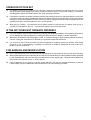
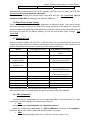
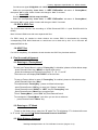
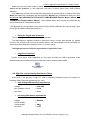
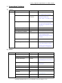
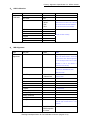
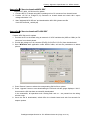
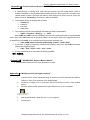
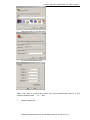
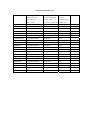
Service Manual CHASSIS MT62B Contents 1. Caution…………………………………......….…………………...……………2 2. Product Specification………………………..……………………...…….…….6 3. Test and Alignment………………….………………………………...………..7 4. Panel List……………….……………………………………………...……….21 5. Notice………………………………….…….. .......................……..22 1 CAUTION: Use of controls, adjustments or procedures other than those specified herein may result in hazardous radiation exposure. CA UTION: TO REDUCE THE RISK OF ELECTRICAL SHOCK, DO NOT REMOVE COVER (OR BACK). NO USER SERVICEABLE PARTS INSIDE. REFER SER VICING TO QUALIFIED SERVICE PERSONNEL. CAUTION RISK OF ELECTRIC SHOCK DO NOT OPEN. The lighting flash with arrowhead symbol, with an equilateral triangle is intended to alert the user to the presence of uninsulated dangerous voltage within the products enclosure that may be of sufficient magnitude to constitute a risk of electric shock to the person. The exclamation point within an equilateral triangle is intended to alert the user to the presence of important operating and maintenance (servicing) instructions in the literature accompanying the appliance. WARNING: TO REDUCE RISK OF FIRE OR ELECTRIC SHOCK, DO NOT EXPOSE THIS APPLIANCE TO RAIN OR MOISTURE. 2 IMPORTANT SAFETY INSTRUCTIONS CAUTION: Read all of these instructions. Save these instructions for later use. Follow all Warnings and Instructions marked on the audio equipment. 1. Read Instructions- All the safety and operating instructions should be read before the product is operated. 2. Retain Instructions- The safety and operating instructions should be retained for future reference. 3. Heed Warnings- All warnings on the product and in the operating instructions should be adhered to. 4. Follow Instructions- All operating and use instructions should be followed. FOR YOUR PERSONAL SAFETY 1. When the power cord or plug is damaged or frayed, unplug this television set from the wall outlet and refer servicing to qualified service personnel. 2. Do not overload wall outlets and extension cords as this can result in fire or electric shock. 3. Do not allow anything to rest on or roll over the power cord, and do not place the TV where power cord is subject to traffic or abuse. This may result in a shock or fire hazard. 4. Do not attempt to service this television set yourself as opening or removing covers may expose you to dangerous voltage or other hazards. Refer all servicing to qualified service personnel. 5. Never push objects of any kind into this television set through cabinet slots as they may touch dangerous voltage points or short out parts that could result in a fire or electric shock. Never spill liquid of any kind on the television set. 6. If the television set has been dropped or the cabinet has been damaged, unplug this television set from the wall outlet and refer servicing to qualified service personnel. 7. If liquid has been spilled into the television set, unplug this television set from the wall outlet and refer servicing to qualified service personnel. 8. Do not subject your television set to impact of any kind. Be particularly careful not to damage the picture tube surface. 9. Unplug this television set from the wall outlet before cleaning. Do not use liquid cleaners or aerosol cleaners. Use a damp cloth for cleaning. 10.1. Do not place this television set on an unstable cart, stand, or table. The television set may fall, causing serious injury to a child or an adult, and serious damage to the appliance. Use only with a cart or stand recommended by the manufacturer, or sold with the television set. Wall or shelf mounting should follow the manufacturer s instructions, and should use a mounting kit approved by the manufacturer. 10.2. An appliance and cart combination should be moved with care. Quick stops, excessive force, and uneven surfaces may cause the appliance and cart combination to overturn. 3 PROTECTION AND LOCATION OF YOUR SET 11. Do not use this television set near water ... for example, near a bathtub, washbowl, kitchen sink, or laundry tub, in a wet basement, or near a swimming pool, etc. Never expose the set to rain or water. If the set has been exposed to rain or water, unplug the set from the wall outlet and refer servicing to qualified service personnel. 12. Choose a place where light (artificial or sunlight) does not shine directly on the screen. 13. Avoid dusty places, since piling up of dust inside TV chassis may cause failure of the set when high humidity persists. 14. The set has slots, or openings in the cabinet for ventilation purposes, to provide reliable operation of the receiver, to protect it from overheating. These openings must not be blocked or covered. Never cover the slots or openings with cloth or other material. Never block the bottom ventilation slots of the set by placing it on a bed, sofa, rug, etc. Never place the set near or over a radiator or heat register. Never place the set in a built-in enclosure, unless proper ventilation is provided. PROTECTION AND LOCATION OF YOUR SET 15.1. If an outside antenna is connected to the television set, be sure the antenna system is grounded so as to provide some protection against voltage surges and built up static charges, Section 810 of the National Electrical Code, NFPA No. 70-1975, provides information with respect to proper grounding of the mast and supporting structure, grounding of the lead-in wire to an antenna discharge unit, size of grounding conductors, location of antenna discharge unit, connection to grounding electrode, and requirements for the grounding electrode. EXAMPLE OF ANTENNA GROUNDING AS PER NATIONAL ELECTRICAL CODE INSTRUCTIONS EXAMPLE OF ANTENNA GROUNDING AS PER NATIONAL ELECTRICAL CODE ANTENNA LEAD- IN WIRE GROUND CLAMP ANTENNA DISCHARGE UNIT (NEC SECTION 810-20) GROUNDING CONDUCTORS (NEC SECTION 810-21) ELECTRIC SERVICE EQUIPMENT GROUND CLAMPS POWER SERVICE GROUNDING ELECTRODE SYSTEM (NEC ART 250. PART H) NEC-NATIONAL ELECTRICAL CODE 15.2. Note to CATV system installer : (Only for the television set with CATV reception) This reminder is provided to call the CATV system installer s attention to Article 820-40 of the NEC that provides guidelines for proper grounding and, in particular, specifies that the cable ground shall be connected to the grounding system of the building, as close to the point of cable entry as practical. 16. An outside antenna system should not be located in the vicinity of overhead power lines or other electric lights or power circuits, or where it can fall into such power lines or circuits. When installing an outside antenna system, extreme care should be taken to keep from touching such power lines or circuits as contact with them might be fatal. 17. For added protection for this television set during a lightning storm, or when it is left unattended and unused for long periods of time, unplug it from the wall outlet and disconnect the antenna. This will prevent damage due to lightning and power-line surges. 4 OPERATION OF YOUR SET 18. This television set should be operated only from the type of power source indicated on the marking label.If you are not sure of the type of power supply at your home, consult your television dealer or local power company. For television sets designed to operate from battery power, refer to the operating instructions. 19. If the television set does not operate normally by following the operating instructions, unplug this television set from the wall outlet and refer servicing to qualified service personnel. Adjust only those controls that are covered in the operating instructions as improper adjustment of other controls may result in damage and will often require extensive work by a qualified technician to restore the television set to normal operation. 20. When going on a holiday : If your television set is to remain unused for a period of time, for instance, when you go on a holiday, turn the television set off and unplug the television set from the wall outlet. IF THE SET DOES NOT OPERATE PROPERLY 21. If you are unable to restore normal operation by following the detailed procedure in your operating instructions, do not attempt any further adjustment. Unplug the set and call your dealer or service technician. 22. Whenever the television set is damaged or fails, or a distinct change in performance indicates a need for service, unplug the set and have it checked by a professional service technician. 23. It is normal for some TV sets to make occasional snapping or popping sounds, particularly when being turned on or off. If the snapping or popping is continuous or frequent, unplug the set and consult your dealer or service technician. FOR SERVICE AND MODIFICATION 24. Do not use attachments not recommended by the television set manufacturer as they may cause hazards. 25. When replacement parts are required, be sure the service technician has used replacement parts specified by the manufacturer that have the same characteristics as the original part. Unauthorized substitutions may result in fire, electric shock, or other hazards. 26. Upon completion of any service or repairs to the television set, ask the service technician to perform routine safety checks to determine that the television is in safe operating condition. 5 Market Set Level Panel Level Front End + Digital requiremen t Picture Sound Feature Picture Going Price Euro at Intro. Target Volume (in FY2009) (K) Intro date/month/qtr. Project Start date Key Distrubution Channel/s Type Classification Sizes Chassis platfrom Styling Panel Type BLU Resoulution 60Hz/120Hz Contrast Ratio Brightness View Angle Anti reflex coated glass Dynamic Contrast Light sensor Backlight Contrast Anlogue/Digital MPEG2 MPEG4 DVB‐T/ T2/ C frontend MHEG 1.06 CI(PCMCIA) CI+ OAD DVBT CVBS output Comb Filter De‐interlacing Sound Output No of Speakers Mono/Stereo/BBE MEMC Teletext No of pages(Teletext) Close Caption HD Video Playback MP3 Playback Photo viewer+Photoframe OSD Languages 32HE9234 37FE9234 40FE9234 42FE9234 46FE9234 52FE9234 End of 2008 2008‐7‐15 MM, BG, CH, TS Large Screen 32W MT5362H E9A Classic CCFL HD 60Hz Supplier to specify 400nits or Less Supplier to specify Supplier to specify Yes End of 2008 2008‐7‐15 MM, BG, CH, TS Large Screen 37W MT5362H E9A Classic CCFL FHD 60Hz Supplier to specify 400nits or Less Supplier to specify Supplier to specify Yes End of 2008 2008‐7‐15 MM, BG, CH, TS Large Screen 40W MT5362H E9A Classic CCFL FHD 60Hz Supplier to specify 400nits or Less Supplier to specify Supplier to specify Yes End of 2008 2008‐7‐15 MM, BG, CH, TS Large Screen 42W MT5362H E9A Classic CCFL FHD 60Hz Supplier to specify 400nits or Less Supplier to specify Supplier to specify Yes End of 2008 2008‐7‐15 MM, BG, CH, TS Large Screen 46W MT5362H E9A Classic CCFL FHD 60Hz Supplier to specify 400nits or Less Supplier to specify Supplier to specify Yes End of 2008 2008‐7‐15 MM, BG, CH, TS Large Screen 52W MT5362H E9A Classic CCFL FHD 60Hz Supplier to specify 400nits or Less Supplier to specify Supplier to specify Yes Yes Digital Yes Yes DVB‐T Yes Digital Yes Yes DVB‐T Yes Digital Yes Yes DVB‐T Yes Digital Yes Yes DVB‐T Yes Digital Yes Yes DVB‐T Yes Digital Yes Yes DVB‐T Yes Yes Yes Yes Yes Yes Yes 3D 3D 2 X 8W 2 Stereo ‐ Teletext 1.5 1000p No No No No Bulgarian, Croatian, Czech, Danish, Dutch, English, Finnish, French, German, Greek, Hungarian, Italian, Norwegian, Polish, Portuguese, Romanian, Russian, Serbian, Slovakian, Slovenian, Spanish, Swedish, Turkish, Ukrainian PAT PIP/PAT/PAP/PIC/PAC PVR (USB) Picture freeze Picture zoom Color tone adjustment Switch on Time Overscan switch off PC capability (up to maximum form Rear CVBS in Rear CVBS out Rear YPbPr Rear HDMI Audio Output Rear SCART 1 Connectivit SCART 2 y PC Input SPDIF Headphone jack Ethernet (RJ‐45) USB connector Side CVBS in Side Side HDMI Connectivit Side Headphone y Side USB No of keys Local Keyboar Front/Side Front Cabinet Back Cabinet DVD slot in Mechanical Remote control Table Top Stand Swivel Stand Voltage Range Standby Power Misc VESA Mount Desination PBS Level one requirements No 5‐7 seconds Yes WXGA No No 1 2 No Yes Yes Yes Yes Yes(PC Input) No No Yes 1 1 Yes 6 Side High Gloss In mould textured No TBD Yes Yes 230V < 1W Yes Whole Europe No Yes 3D 3D 2 X 8W 2 Stereo ‐ Teletext 1.5 1000p No No No No Bulgarian, Croatian, Czech, Danish, Dutch, English, Finnish, French, German, Greek, Hungarian, Italian, Norwegian, Polish, Portuguese, Romanian, Russian, Serbian, Slovakian, Slovenian, Spanish, Swedish, Turkish, Ukrainian PAT No 5‐7 seconds Yes WXGA No No 1 2 No Yes Yes Yes Yes Yes(PC Input) No No Yes 1 1 Yes 6 Side High Gloss In mould textured No TBD Yes Yes 230V < 1W Yes Whole Europe No Yes 3D 3D 2 X 8W 2 Stereo ‐ Teletext 1.5 1000p No No No No Bulgarian, Croatian, Czech, Danish, Dutch, English, Finnish, French, German, Greek, Hungarian, Italian, Norwegian, Polish, Portuguese, Romanian, Russian, Serbian, Slovakian, Slovenian, Spanish, Swedish, Turkish, Ukrainian PAT No 5‐7 seconds Yes WXGA No No 1 2 No Yes Yes Yes Yes Yes(PC Input) No No Yes 1 1 Yes 6 Side High Gloss In mould textured No TBD Yes Yes 230V < 1W Yes Whole Europe No Yes 3D 3D 2 X 8W 2 Stereo ‐ Teletext 1.5 1000p No No No No Bulgarian, Croatian, Czech, Danish, Dutch, English, Finnish, French, German, Greek, Hungarian, Italian, Norwegian, Polish, Portuguese, Romanian, Russian, Serbian, Slovakian, Slovenian, Spanish, Swedish, Turkish, Ukrainian PAT No 5‐7 seconds Yes WXGA No No 1 2 No Yes Yes Yes Yes Yes(PC Input) No No Yes 1 1 Yes 6 Side High Gloss In mould textured No TBD Yes Yes 230V < 1W Yes Whole Europe No Yes 3D 3D 2 X 8W 2 Stereo ‐ Teletext 1.5 1000p No No No No Bulgarian, Croatian, Czech, Danish, Dutch, English, Finnish, French, German, Greek, Hungarian, Italian, Norwegian, Polish, Portuguese, Romanian, Russian, Serbian, Slovakian, Slovenian, Spanish, Swedish, Turkish, Ukrainian PAT No 5‐7 seconds Yes WXGA No No 1 2 No Yes Yes Yes Yes Yes(PC Input) No No Yes 1 1 Yes 6 Side High Gloss In mould textured No TBD Yes Yes 230V < 1W Yes Whole Europe No Yes 3D 3D 2 X 8W 2 Stereo ‐ Teletext 1.5 1000p No No No No Bulgarian, Croatian, Czech, Danish, Dutch, English, Finnish, French, German, Greek, Hungarian, Italian, Norwegian, Polish, Portuguese, Romanian, Russian, Serbian, Slovakian, Slovenian, Spanish, Swedish, Turkish, Ukrainian PAT No 5‐7 seconds Yes WXGA No No 1 2 No Yes Yes Yes Yes Yes(PC Input) No No Yes 1 1 Yes 6 Side High Gloss In mould textured No TBD Yes Yes 230V < 1W Yes Whole Europe Yes 19HR3224 2009‐4‐30 2008‐7‐15 MM, BG, CH, TS Small Screen 19W MT5362H Value‐M19 Classic CCFL HD 60Hz Supplier to specify Less 400nits Supplier to specify Supplier to specify Yes Yes Yes Digital Yes Yes DVB‐T/C Yes Yes No Yes Yes 3D 3D 2 X 3W 2 Stereo No Teletext 1.5 1000p No Yes Yes Yes Bulgarian, Croatian, Czech, Danish, Dutch, English, Finnish, French, German, Greek, Hungarian, Italian, Norwegian, Polish, Portuguese, Romanian, Russian, Serbian, Slovakian, Slovenian, Spanish, Swedish, Turkish, Ukrainian PAT No Yes Yes No 5‐7 seconds Yes WXGA No No 1 1 No Yes No Yes Yes Yes(PC Input) No No Yes No 1 Yes 6 Side High Gloss In mould textured No TBD M19 stand No 230V < 1W Yes Whole Europe Yes 22HR3224 2009‐4‐30 2008‐7‐15 MM, BG, CH, TS Small Screen 22W MT5362H Value‐M19 Classic CCFL HD 60Hz Supplier to specify Less 400nits Supplier to specify Supplier to specify Yes Yes Yes Digital Yes Yes DVB‐T/C Yes Yes No Yes Yes 3D 3D 2 X 3W 2 Stereo No Teletext 1.5 1000p No Yes Yes Yes Bulgarian, Croatian, Czech, Danish, Dutch, English, Finnish, French, German, Greek, Hungarian, Italian, Norwegian, Polish, Portuguese, Romanian, Russian, Serbian, Slovakian, Slovenian, Spanish, Swedish, Turkish, Ukrainian PAT No Yes Yes No 5‐7 seconds Yes WXGA No No 1 1 No Yes No Yes Yes Yes(PC Input) No No Yes No 1 Yes 6 Side High Gloss In mould textured Yes TBD M19 stand No 230V < 1W Yes Whole Europe Yes 26HR3224 2009‐4‐30 2008‐7‐15 MM, BG, CH, TS Small Screen 26W MT5362H Value‐M19 Classic CCFL HD 60Hz Supplier to specify Less 400nits Supplier to specify Supplier to specify Yes Yes Yes Digital Yes Yes DVB‐T/C Yes Yes No Yes Yes 3D 3D 2 X 3W 2 Stereo No Teletext 1.5 1000p No Yes Yes Yes Bulgarian, Croatian, Czech, Danish, Dutch, English, Finnish, French, German, Greek, Hungarian, Italian, Norwegian, Polish, Portuguese, Romanian, Russian, Serbian, Slovakian, Slovenian, Spanish, Swedish, Turkish, Ukrainian PAT No Yes Yes No 5‐7 seconds Yes WXGA No No 1 1 No Yes Yes Yes Yes Yes(PC Input) No No Yes 1 1 Yes 6 Side High Gloss In mould textured Yes TBD M19 stand No 230V < 1W Yes Whole Europe Yes 32HR3224 2009‐4‐30 2008‐7‐15 MM, BG, CH, TS Large Screen 32W MT5362H Value‐M19 Classic CCFL HD 60Hz Supplier to specify Less 400nits Supplier to specify Supplier to specify Yes Yes Yes Digital Yes Yes DVB‐T/C Yes Yes No Yes Yes 3D 3D 2 X 8W 2 Stereo No Teletext 1.5 1000p No Yes Yes Yes Bulgarian, Croatian, Czech, Danish, Dutch, English, Finnish, French, German, Greek, Hungarian, Italian, Norwegian, Polish, Portuguese, Romanian, Russian, Serbian, Slovakian, Slovenian, Spanish, Swedish, Turkish, Ukrainian PAT/ PIP/PAP/PIC/PAC No Yes Yes No 5‐7 seconds Yes WXGA No No 1 1 No Yes Yes Yes Yes Yes(PC Input) No No Yes 1 1 Yes 6 Side High Gloss In mould textured Yes TBD M19 stand No 230V < 1W Yes Whole Europe Yes 40FR3234 2009‐4‐30 2008‐7‐15 MM, BG, CH, TS Large Screen 40W MT5362H Value‐M19 Classic CCFL FHD 60Hz Supplier to specify Less 400nits Supplier to specify Supplier to specify Yes Yes Yes Digital Yes Yes DVB‐T/C Yes Yes No Yes Yes 3D 3D 2 X 8W 2 Stereo No Teletext 1.5 1000p No Yes Yes Yes Bulgarian, Croatian, Czech, Danish, Dutch, English, Finnish, French, German, Greek, Hungarian, Italian, Norwegian, Polish, Portuguese, Romanian, Russian, Serbian, Slovakian, Slovenian, Spanish, Swedish, Turkish, Ukrainian PAT/ PIP/PAP/PIC/PAC Phase 3 TBC Yes Yes No 5‐7 seconds Yes WXGA No No 1 2 No Yes Yes Yes Yes Yes(PC Input) No No Yes 1 1 Yes 6 Side High Gloss In mould textured No TBD J‐Class stand No 230V < 1W Yes Whole Europe Yes 46FR3234 2009‐4‐30 2008‐7‐15 MM, BG, CH, TS Large Screen 46W MT5362H Value‐M19 Classic CCFL FHD 60Hz Supplier to specify Less 400nits Supplier to specify Supplier to specify Yes Yes Yes Digital Yes Yes DVB‐T/C Yes Yes No Yes Yes 3D 3D 2 X 8W 2 Stereo No Teletext 1.5 1000p No Yes Yes Yes Bulgarian, Croatian, Czech, Danish, Dutch, English, Finnish, French, German, Greek, Hungarian, Italian, Norwegian, Polish, Portuguese, Romanian, Russian, Serbian, Slovakian, Slovenian, Spanish, Swedish, Turkish, Ukrainian PAT/ PIP/PAP/PIC/PAC Phase 3 TBC Yes Yes No 5‐7 seconds Yes WXGA No No 1 2 No Yes Yes Yes Yes Yes(PC Input) No No Yes 1 1 Yes 6 Side High Gloss In mould textured No TBD J‐Class stand No 230V < 1W Yes Whole Europe Yes Factory Alignment Specification for MT62 chassis TCL WW R&D FPD CENTER Factory Alignment Specification CHASSIS:MT62 Version:V0.50 PREPARED BY : APPROVED BY : Wei Lin DATE : 2009-05-06 DATE : TestAlignmentSpecification for TCL-MT5362-V0.50.doc (Page 1 of 14) Factory Alignment Specification for MT62 chassis Disclosure The information contained in this document is proprietary to TCL SZ FPD lab and shall not be disclosed by the recipient to third persons without the written permission of the team leader or GM of R&D. Revision History Status, Ver Date, Drafter Description of changes V0.10 22/09/08 The item in gray is invalid V0.20 28/09/08 The item in gray is invalid Factory Menu is improved V0.30 08/10/08 Add Panel ID check Working range changed to 220 ~ 240 VAC V0.40 28/11/08 Add Sound Curve control on factory menu Add Scart RGB ADC Calibration Improve ADC Calibration menu and WD Alignment menu Add Panel ID for new models V0.50 06/05/09 Improve WD Alignment menu Panel ID is deleted. It can be found in another document:<Panel list for MT62> TestAlignmentSpecification for TCL-MT5362-V0.50.doc (Page 2 of 14) Factory Alignment Specification for MT62 chassis The MT62 chassis is designed for European LCD TV. The main chip is from Mediatec (MTK5362 series) and supports below inputs: • • • • • • • one analog and digital mixed RF (PAL B/G D/K I, SECAM B/G D/K L/L’,DVB-T) one Side AV(CVBS ) one SCART (CVBS & RGB) one SCART (CVBS & YC) one CMP (YPrPb can support from 480i up to 1080p) one VGA three HDMI (can support 480i/p, 576i/p, 720p up to 1080i/p) compliant v1.2. with HDCP, audio included as EIA-861B standard • one Headphone output • one SPDIF output More relevant details are listed into the Spec.. INFO: ª All tests and measurements mentioned hereafter have to be carried out at a normal mains voltage (220 ~ 240 VAC) ª All voltages have to be measured with respect to ground, unless otherwise stated ª All final tests have to be done on a complete set including LCD panel in a room with temperature of 25+/-7°C ª The White Balance (color temperature) has to be performed into subdued lighted room after at least 1 hour of warm-up/burn-in. This is applicable for both Alignment and Picture Performance evaluation at OQA in order to be set free of any temperature drift ( colorimetry vs time) 1. Electrical Assembly Alignment 1.1. Preconditions – DC/DC Check Before Power On the chassis, please check and make sure that U811,U9,U31, U7, U6, U11, U5,U4,U34,C74(positive) , C62(positive) , C76(positive) , C152(positive) , C89(positive) , C82(positive) outputs are not shorted to ground. Supply voltage to P19 and test the relative voltage. Supply P19 : Pin5,6,8=12v (24v work with IPB PSU);Pin11,12=5v;Pin1,2=Voltage for sound Amplifier IC (18V for 46/52 inch;12V for other inch ) Test the relative voltage: position value note These are necessary C152(positive) 24V +/-5% only work with IPB PSU C89(positive) 12V +/-5% C82(positive) U811 C74(positive) U9 U31 U7 U6 U5 U4 C62(positive) 12V 3.3V 5.0V 3.3V 3.3V 1.2V 2.5V 9.0V 5.0V 1.8V +/-5% +/-5% +/-5% +/-5% +/-5% +/-5% +/-5% +/-5% +/-5% +/-5% TestAlignmentSpecification for TCL-MT5362-V0.50.doc (Page 3 of 14) Factory Alignment Specification for MT62 chassis C76(positive) 1.0V +/-5% 1.0V +/-5% Download latest release MCU_SW into the Standby CPU(U3) using WT_MCU_ISP SW tool. See Appendixn “How to download MCU SW”. Download latest release SW into the flash using MTK SW tool. See Appendixo “How to download FLASH SW”. Or download the SW from USB port. 1.2. Panel ID check and modify There is different ID stored in the NVM depended on different Panels. The correct number should be checked in factory menu and if not correct according to the panel list , should be correct manually.The simple way is that select the correct Id in factory menu and restart the set.If the wrong ID make the set display nothing, it must be correct with Hyper terminal . See Appendixr 1.3. Functional Test Once the boards (chassis, KB, IR, PSU…) and the panel are well interconnected, connect all external generator devices to relevant inputs/outputs below according to their respective test patterns format and check picture content and sound quality accordingly: Source Test signal (generator) Test pattern (format/image) Analog /Digital Tuner RF cable Full Band (VHF/UHF) + CATV DVB-T Composite(CVBS) Chroma/Fluke PAL Half Color & Gray bars SCART1 (CVBS) Chroma/Fluke PAL Half Color & Gray bars SCART1 (RGB) Half Color & Gray bars SCART2 (CVBS) Chroma/Fluke PAL Half Color & Gray bars SCART2 (Y/C) VGA Chroma/QuantumData 1024x768@60Hz Half Color & Gray bars Component (YPrPb) Chroma/QuantumData 1080i@60Hz Half Color & Gray bars HDMI1/ HDMI2/ HDMI3 DVD with HDMI compliancy Movie 720p@60Hz Headphone RF cable First channel Loud Speakers RF cable First channel SCART1 (CVBS out) RF cable First channel SCART2 (CVBS out) Chroma/Fluke PAL Half Color & Gray bars Audio tones can be defined by the factory (ie: 1KHz & 3KHz, sweep, …). Picture video formats can be changed by the factory according to their own standard. 1.4. ADC Calibration To ensure the ADC performance, the error of “generator+cable” must be less than 2%. Three inputs require an ADC calibration for the time being, They are: VGA Provide a test signal 1024×768@60Hz with WhiteBlack squares. Select the corresponding “Auto Color” in “ADC Calibration” sub-menu of “FactoryMenu”, then press ”OK” to start. Value of status will change to “ALL” if succeed. CMP TestAlignmentSpecification for TCL-MT5362-V0.50.doc (Page 4 of 14) Factory Alignment Specification for MT62 chassis Provide a test signal 576i@50Hz with 100% 8 steps ColorBar. Select the corresponding “Auto Color” in “ADC Calibration” sub-menu of “FactoryMenu”, then press ”OK” to start. Value of status wil change to “ALL” if succeed. Scart RGB Provide a test signal 100% 8 steps ColorBar. Select the corresponding “Auto Color” in “ADC Calibration” sub-menu of “FactoryMenu”, then press ”OK” to start. Value of status will change to “ALL” if succeed. 1.5. DDC & EDID Test The E-EDID data structure are according to VESA Enhanced EDID 1.3 (and EIA/CEA-861B for HDMI). Both VGA and HDMI have their own separate bin files: For EDID check, it’s needed to check whether the correct EDID is downloaded by checking corresponding EDID NVM Checksum or read them out to check bit by bit if it is in line with the released EDID bin file. 1.6. HDCP Test For HDCP compliancy, it’s needed to check whether the HDCP key has been well set. 2. Final Assembly Alignment 2.1. Entering to “FactoryMenu” To enter into Factory Menu in case of “FactoryKey” is disabled, please to follow below steps: - press RemoteControl key “MENU” to display main menu - press the subsequence RemoteControl keys “7”, “9”, “1” and “5” The main menu will display”FACTCORY” at the last item To pop-up Factory Menu in case of “FactoryKey” is enabled, please to follow below step: - press RemoteControl key “Blue” To enable/disable “FactoryKey”, please to follow below steps: - press RemoteControl “OK”key to enter into “System” submenu - press RemoteControl “RIGHT”or “LEFT” key till “FactoryKey” item - press RemoteControl “Menu”key to toggle mode To exit “FactoryMenu”, press “Exit” key from RemoteControl. To comeback to “FactoryMenu” root when you are into a submenu: - press RemoteControl “Menu” key. 2.2. Entering to “P” Mode Turned on the factory key to enter into “P” mode.The TV will display “P” in bottom left corner in “P” mode. See appendixp “Serial Command Protocol for MTKxx”. 2.3. White Balance Alignment TestAlignmentSpecification for TCL-MT5362-V0.50.doc (Page 5 of 14) Factory Alignment Specification for MT62 chassis Make sure that the picture mode is “vivid”, enter to “P” mode(turned on the factory key) and switch off “Pic. Enhance” in “WD Alignment” sub-menu of factory menu before white balance alignment . Only VGA input requires color temperature adjustment as all other inputs or relative ones. Both Warm and Cool Color Coordinates are also relatives to Normal Color Temperature mode ones. See appendixq “PAL/SECAM/NTSC/DTV/SCART RGB/CMP/HDMI Relative Matrix Offsets” and “WARM/COOL Relative Matrix Offsets”. Those offsets values don’t require any alignment but can be fine-tuned in FactoryMenu as well. <The appendix is just a template, Every lot the relative offset is different. We need to align 5 sets first to get the relative offset data every lot. > Expected Targets and Tolerances The measured parameters should be “x, y” coordinates. The White Balance alignment should be performed using a contact less analyzer (ei: Minolta CA-210). The analyzer may not touch the screen surface, and measurement must be performed in a dark environment keeping the probe(s) at 90+/-2° from the panel. The alignment have to fulfill the requirements in Application Form. Alignment FlowChart Provide a test signal 1024×768@60Hz on VGA input and align the WB as described inside attached document ensuring first that the BackLight value is matching below table: MTK_EuroAlignmentF lowchart.doc 2.4. High Pot. and Insulating Resistance Tests At the end of the process, a High Pot. and an Insulating Resistance tests are required for matching Safety Electrical requirements (ei: xxxx) High Voltage Withstanding requirements - “Voltage” - “Max Leakage Current” - “Test Time” Ö 4240 VDC Ö 1 mA Ö 3 sec Insulating Resistance requirements - “Voltage” - “Threshold Max” - “Threshold Min” Ö DC500V Ö Ö 4MΩ - “Test Time” Ö 3 sec TestAlignmentSpecification for TCL-MT5362-V0.50.doc (Page 6 of 14) Factory Alignment Specification for MT62 chassis 3. “Factory Menu” Definition 1). System Item Sub-item Value Note System Factory Key Off/On OFF:hotkey is invalid ON :hotkey(blue key) is availability Power Mode Boot/Standby/ Previous Boot: Enter power on mode Standby: Enter standby mode Previous: power on according to last status Burning Mode Off/On Select panel On with left/right key, Press “EXIT” key to enter the burning mode; Press “Menu” key on keyboard to exit the burning mode Pre-Frequency Poland Run Press “OK” key to run Pre-Frequency Huizhou Run Press “OK” key to run Pre-Frequency Thailand Run Press “OK” key to run Reset User Clear date of NVM in user menu,except the value of language / related installation/Factory setting,then set to the default value. Reset All clear NVM values,and set to default value。 Reset Shop Clear date of NVM in user menu,include the value related installation,and Clear date of factory menu except the item of Balance and sound ,set to default value 2).Feature Item Sub-item Value Feature FleshTone Off/On Adaptive Luma Control Off/On Dynamic BackLight On/Off Note Dynamic BackLight On: adapt to picture Dynamic BackLight Off: fix by back light value Light sensor Off/On Only the models with M19 front cabinet have this feature. Back light 0~100 White Peak Limitator Off/On TunerAGC 0~31 Panel ID ID Select panel ID with left/right key, restart the set to take effect. VT character set default language Delnterlace Mode Mode* Select language with left/right key TestAlignmentSpecification for TCL-MT5362-V0.50.doc (Page 7 of 14) Factory Alignment Specification for MT62 chassis 3). ADC Calibration Item Sub-item ADC Calibration Source Value Note VGA\CMP\scart RGB require Calibration Auto color Run Press “OK” key to run Status NONE / NOK / OK / ALL NONE:No source has been calibrated NOK:Current source hasn’t been calibrated OK: Current source has been calibrated ALL:All sources have been calibrated R Gain G Gain B Gain For fine tune ADC manually. R Offset G Offset B Offset 4). WD Alignment Item Sub-item Value Note WD Alignment Pic. Enhance ON/OFF Press “Right” key to switch off all of the items in the feature submenu. This should be done before white balance alignment. If it’s off, the way to switch it on is to reset user/shop or set on the features in Feature sub-item manually. Source PAL/SECAM… … For balance source: VGA,DTV,PAL,SECAM,NTSC,Scart RGB,CPM, HDMI Color Temperature Normal /Warm/Cool The value of Warm and cool is the offset of Normal mode. R Gain R White balance G Gain G White balance B Gain B White balance R Offset R Gray balance G Offset G Gray balance B Offset B Gray balance Scaling Brightness Scaling Contrast Scaling Saturation Auto phase Run Press “OK” key to adjust the signal to avoid the ripple in CMP source, it is not necessary. SCART 1 Auto/Mixed/R GB/Composite /S-Video TestAlignmentSpecification for TCL-MT5362-V0.50.doc (Page 8 of 14) Factory Alignment Specification for MT62 chassis SCART 2 Auto/Composit e/S-Video Item Sub-item Value Sound VOL_0 0 VOL_10 2 VOL_50 14 VOL_90 135 VOL_100 255 TV Pre 186 AV Pre 186 5).Sound Note 6).Geometry (This item effective only in TV source) Item Sub-item Geometry source Value Note H.Position H.Size V.Position V.Size 7). Version info Version info Project Panel Version Date MCU Version 4.Factory default settings Followed as OOB setting. TestAlignmentSpecification for TCL-MT5362-V0.50.doc (Page 9 of 14) Factory Alignment Specification for MT62 chassis Appendix n “How to download MCU SW” Prepare WT_MCU_ISP SW tool for update. 1. Connect the PC to board using MCU updating tool on P6 connector form chassis board. 2. Provide +5V DC on P19(pin11,12) connector on chassis board and check U811 output voltage should be 3.3V. 3. Start “Weltrend MCU ISP.exe” and download the MCU SW. (please see file Visio-ISPToolGuide_ver090.pdf) Appendix o “How to download FLASH SW” Prepare MTK SW tool for update. 1. Connect the PC to the board using an external +3.3VDC serial device (USB or COMx) on P9 connector from chassis board. 2. Provide the voltage on P19 connector (Pin5,6,8=12v;Pin11,12=5v) from chassis board 3. Start “MTKTOOL.exe” application under MTKxx folder, and set the parameters as below picture: 4. Press “Browse” button to select the corresponding SW bin file to upload 5. Press “Upgrade” button to start downloading the SW and wait the gauge displayed “100%” that means the SW has been successfully downloaded. In the meanwhile, all operations such erasing flash and so… are parsed into the debug window script. 6. Once the SW is downloaded, switch-off/on the chassis board and wait few seconds for eeprom update. TestAlignmentSpecification for TCL-MT5362-V0.50.doc (Page 10 of 14) Factory Alignment Specification for MT62 chassis Appendix p “Serial Command Protocol for MTKxx” 1. A serial protocol for driving MTK µchip through external +3.3VDC serial device (USB or COMx) is available. It may facilitate manufacturing process. Thus, both P201 connector from chassis board or either VGA input can also be used using pin12 (RXD) & pin15 (TXD) just taking care that “FactoryKey” from Factory Menu is enabled. 2. The required serial port settings are as below • 115200 bps • 8 data bit • 1 bit stop • none parity 3. The command format is like hereafter described into BNS representation: • 0xBB + Command + Data[[..] + ..] + 0xEE Both 0xBB and 0xEE bytes are mandatory and used as header and footer of the transmitted frame. Apart from INIT frame that is described further, all sent bytes need to be triggered before by an additional one as 0x50. So a complete frame might match following one: • 0x50+0xBB+0x50+Command+0x50+Data[[..]+0x50+..]+0x50+0xEE 4. At first time, it might be required to initialize MTK µchip by using once below INIT command (without any triggering byte): • 0x02 + 0x00 + 0x00 + 0x13 + 0x01 + 0x00 5. A none exhaustive list of commands is already available. 错误!链接无效。 Appendix q “ WARM/COOL Relative Matrix Offsets” 1. These offsets should be done in the production by AOE. Appendix r “Modify panel ID with Hyper terminal” ①. ②. ③. Connect the PC to the mainboard using an external +3.3VDC serial device (USB or COMx) on P9 or P18 connector from chassis board. Provide the voltage on P19 connector (Pin5,6,8=12v;Pin11,12=5v) from chassis board Save the password file “password for hyperTerminal.txt” to your computer. D:\MT62\调试说明\ 已发布\password f ④. ⑤. Start HyperTerminal “HyperTrm.exe” in your computer. Fill the name. TestAlignmentSpecification for TCL-MT5362-V0.50.doc (Page 11 of 14) Factory Alignment Specification for MT62 chassis ⑥. Select the Com Port you are using. ⑦. Set the items as below picture. . Select “File->Save->” to Save the setting. Then start HyperTerminal “atsc.ht” in your computer instead of step ③ to ⑦ later ⑧. Send the password. TestAlignmentSpecification for TCL-MT5362-V0.50.doc (Page 12 of 14) Factory Alignment Specification for MT62 chassis ⑨. Select the password file saved in your computer. ⑩. Under the folder “DTV>” enter “pmx.s.p +ID”,e.g.: pmx.s.p 102 See the panel ID in another document <Panel list for MT62>. TestAlignmentSpecification for TCL-MT5362-V0.50.doc (Page 13 of 14) Factory Alignment Specification for MT62 chassis . Press “Enter”, the panel signal will be printed in the window TestAlignmentSpecification for TCL-MT5362-V0.50.doc (Page 14 of 14) Panel list for MT62B - V0.2 model name of panel (shown in factory menu->version info->panel ) name of panel ID (can be modified in factory menu ->feature->panel ID) panel ID (can be modified with COM port) 32HE9234 LC320WXN-SBA1 32E9LG8 107 37FE9234 LC370WUN 37E9LGD 106 40FE9234 LTA400HA10 40E9SS8 105 42FE9234 LC420WUN-SAA1 42E9LGA 102 46FE9234 LTA460HB09 46E9SS7 103 52FE9234 LTA520HB09 52E9SS3 104 42FE9234/LGJ LC420WUN-SBA1 42E9LGJ 119 46FE9234/SS9 LTA460HA07 46E9SS9 120 19HR3234 LC190WH1-TLA1 19R3LG1 114 22HR3234 LC220WXE-TBA1 22R3LG1 113 26HR3234 T260XW02 VQ 26R3AU6 112 32HR3234 LC320WXN-SBA1 32R3LG8 115 40FR3234 LTA400HA10 40R3SS8 116 46FR3234 T460HW03 V1 46R3AU1 111 40FF9234 LTA400HA08 40F9SSB 117 46FF9234 LTA460HB08 46F9SS8 118 32HE8234B LC320WXN-SBA1 32E8LG8 121 26HE9234B LC260WXN-SBA1 26E9LG3 122 26HE8234B LC260WXN-SBA1 26E8LG3 123 mark Notice: The Main IC Brief Instruction, Block Diagram and Schematic Diagram on this chassis are the same with chassis MT62, please refer to the Service Manual for MT62 if needed.