1
MX-80F/T
EPSON DOT MATRIX PRINTER
r Operation Manual 3
EPSON
P8093033-1
Copyright 0 1981 by EPSON,
Shinshu Seiki Co., Ltd.
Nagano, Japan
“All rights reserved”
*The contents of this manual are subject to change without notice.
TRS-80 is the registered trademark of Radio Shack,
a Division of Tandy Corporation.
TABLE OF CONTENTS
INTRODUCTION . . . . . . . . . . . . . . . . . . . . .
INSTALLATION. . . . . . . . . . . . . . . . . . . . . .
1. Contents of Carton. . . . . . . . . . . . . . . .
2. Unpacking. . . . . . . . . . . . . . . . . . . . . . . .
2.1. Unpacking steps . . . . . . . . . . . . . . . . .
2.2. Repacking steps. . . . . . . . . . . . . . . . . .
3. Installation of the Printer . . . . . . . . . .
4. Cartridge Ribbon Setting. . . . . . . . . . .
5. Separator Installation. . . . . . . . . . . . . .
6. Dismounting of Tractor Unit. . . . . . . .
7. Paper Loading . . . . . . . . . . . . . . . . . . . .
7.1. Fanfold paper. . . . . . . . . . . . . . . . . . . .
7.1.1.
7.1.2.
7.1.3.
7.1.4.
Loading of fanfold paper . . . . . . . . .
Removal of fanfold paper. . . . . . . . .
Column layout on fanfold paper. ..
Top of form position setting . . . . . .
7.2. Roll paper. . . . . . . . . . . . . . . . . . . . . . .
7.2.1. Roll paper holder. . . . . . . . . . . . . . . .
7.2.2. Loading of roll paper . . . . . . . . . . . .
7.3. Cut paper sheet. . . . . . . . . . . . . . . . . .
7.3.1. Loading of cut paper sheet . . . . . . .
8. Gap Adjustment . . . . . . . . . . . . . . . . . .
9. Power Connection . . . . . . . . . . . . . . . .
OPERATION. . . . . . . . . . . . . . . . . . . . . . . . .
1. Switches and Indicators . . . . . . . . . . .
1.1. Switches . . . . . . . . . . . . . . . . . . . . . . . .
1.2. Indicators . . . . . . . . . . . . . . . . . . . . . . .
2. Buzzer . . . . . . . . . . . . . . . . . . . . . . . . . . .
3. Paper End Detector . . . . . . . . . . . . . . .
4. Self-Test . . . . . . . . . . . . . . . . . . . . . . . . .
5. Construction of MX-80 F/T . . . . . . . .
5.1. Printer mechanism. . . . . . . . . . . . . . . .
5.2. Control circuit board. . . . . . . . . . . . . .
5.3. Power circuit . . . . . . . . . . . . . . . . . . . .
5.4. Printer initialization . . . . . . . . . . . . . . .
6. Setting of DIP Switches. . . . . . . . . . .
7. Parallel Interface. . . . . . . . . . . . . . . . . .
8. Coding Tables . . . . . . . . . . . . . . . . . . . .
9. Control Codes . . . . . . . . . . . . . . . . . . . .
....
.
.
.
. . . .
. . .
...
.
.
.
. .
.
.
...
.
.
. . . . .
.
.
.
.
.
.
. . .
. ...
. .
.
.
.
.
.
.
. .
.
... ...
.
. . . .
. .
.
.
.
-(1)-
.
. . .. . . 1
.
. 2
...... 2
. . . 3
...... 3
...... 3
..,.. 3
.
6
. . . 7
.
8
. . . 9
9
..... 9
11
.
. . . 12
.
12
. . . . 13
. . . . 13
.
. 13
. . . 14
.
. 14
. . . . 18
. . . . 18
. . . 20
. . . 20
.
. 20
.
. 21
.
. 21
.
. 21
.
22
.
. 23
. . . 23
.
. 24
26
26
27
. . . . 28
. . . . 31
.
34
MAINTENANCE . . . . . . . . . . . . . . . . . . . . . . . . .
1. Preventive Maintenance. . . . . . . . . . . . . . .
2. Parts Replacement . . . . . . . . . . . . . . . . . . . .
SPECIFICATIONS . . . . . . . . . . . . . . . . . . . . . . . .
SUMMARY OF CONTROL CODES. . . . . . . . .
APPENDIX . . . . . . . . . . . . . . . . . . . . . . . . . . . . . .
Assembly Instructions on Roll Paper Holder
-(2)--
44
44
44
46
48
49
49
LIST OF FIGURES
Fig. 1 EPSON MX-80 F/T Dot Matrix Printer . . . . . . . . . . . . . . . . . . . . . . . . . . . . . . 1
Fig. 2 Contents of Carton. . . . . . . . . . . . . . . . . . . . . . . . . . . . . . . . . . . . . . . . . . . . . . . 2
Fig. 3 Removal of Shipping Screws . . . . . . . . . . . . . . . . . . . . . . . . . . . . . . . . . . . . . . 4
Fig. 4 Removal of Printer Lid. . . . . . . . . . . . . . . . . . . . . . . . . . . . . . . . . . . . . . . . . . . . 5
Fig. 5 Cartridge Ribbon Setting. . . . . . . . . . . . . . . . . . . . . . . . . . . . . . . . . . . . . . . . . . 6
Fig. 6 Cartridge Ribbon Setting. . . . . . . . . . . . . . . . . . . . . . . . . . . . . . . . . . . . . . . . . . 6
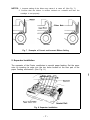
Fig. 7 Examples of Correct and Incorrect Ribbon Setting. . . . . . . . . . . . . . . . . . . . 7
Fig. 8 Separator Installation . . . . . . . . . . . . . . . . . . . . . . . . . . . . . . . . . . . . . . . . . . . . . 7
Fig. 9 Dismounting of Tractor Unit, . . . . . . . . . . . . . . . . . . . . . . . . . . . . . . . . . . . . . . 8
.8
Fig. 10 Mounting of Tractor Unit
Fig. 11 lnsertion of Fanfold Paper................................................................................ . 9
Fig. 12 Raising of Sprocket Lock Levers . . . . . . . . . . . . . . . . . . . . . . . . . . . . . . . . . . 10
Fig. 13 Engagement of Paper Feed Holes on Feeding Pins. . . . . . . . . . . . . . . . . . . 10
Fig. 14 Printer with Fanfold Paper Set Completely . . . . . . . . . . . . . . . . . . . . . . . . . 11
Fig. 15 Example of Paper Arrangement. . . . . . . . . . . . . . . . . . . . . . . . . . . . . . . . . . . 11
Fig. 16 Top of Form Position Setting. . . . . . . . . . . . . . . . . . . . . . . . . . . . . . . . . . . . . 12
Fig. 17 Loading of Roll Paper (1) . . . . . . . . . . . . . . . . . . . . . . . . . . . . . . . . . . . . . . . . 13
Fig. 18 Loading of Roll Paper (2) . . . . . . . . . . . . . . . . . . . . . . . . . . . . . . . . . . . . . . . . 14
Fig. 19 Loading of Roll Paper (3) . . . . . . . . . . . . . . . . . . . . . . . . . . . . . . . . . . . . . . . . 14
Fig. 20 Loading of Cut Paper Sheet. . . . . . . . . . . . . . . . . . . . . . . . . . . . . . . . . . . . . . 15
Fig. 21 Adjustment of Inserted Paper Position . . . . . . . . . . . . . . . . . . . . . . . . . . . . . 15
Fig. 22 Alignment of Side edges. . . . . . . . . . . . . . . . . . . . . . . . . . . . . . . . . . . . . . . . . 16
Fig. 23 Form Position Setting Mark . . . . . . . . . . . . . . . . . . . . . . . . . . . . . . . . . . . . . . 16
Fig. 24 Print Area. . . . . . . . . . . . . . . . . . . . . . . . . . . . . . . . . . . . . . . . . . . . . . . . . . . . . . 16
Fig. 25 Setting of Cut Paper Sheet. . . . . . . . . . . . . . . . . . . . . . . . . . . . . . . . . . . . . . . 17
Fig. 26 Printer with Cut Paper Sheet Set Completely . . . . . . . . . . . . . . . . . . . . . . . 17
Fig. 27 Gap Adjustment. . . . . . . . . . . . . . . . . . . . . . . . . . . . . . . . . . . . . . . . . . . . . . . . 19
Fig. 28 Switches and Indicators on Control Panel . . . . . . . . . . . . . . . . . . . . . . . . . . 20
Fig. 29 Control Circuit Diagram. . . . . . . . . . . . . . . . . . . . . . . . . . . . . . . . . . . . . . . . . . 24
Fig. 30 Driver Circuit Diagram . . . . . . . . . . . . . . . . . . . . . . . . . . . . . . . . . . . . . . . . . . . 25
Fig. 31 Location of DIP Switches . . . . . . . . . . . . . . . . . . . . . . . . . . . . . . . . . . . . . . . . 27
Fig. 32 Parallel Interface Timing . . . . . . . . . . . . . . . . . . . . . . . . . . . . . . . . . . . . . . . . . 31
Fig. 33 Replacement of Print Head. . . . . . . . . . . . . . . . . . . . . . . . . . . . . . . . . . . . . . .45
-(3)-
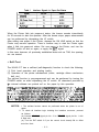
LIST OF TABLES
Interface Signals in Paper-Out Status . . . . . . . . . . . . . . . . . . . . . . . . .
Functions and Conditions of DIPSwitch 1. . . . . . . . . . . . . . . . . . . . . .
Functions and Conditions of DIPSwitch 2. . . . . . . . . . . . . . . . . . . . . .
Special Characters/Symbols Available for Selection
(using DIP Switch Pins 2-1 and 2-2). . . . . . . . . . . . . . . . . . . . . . . . . .
Table 5 Connector Pin Assignment and Descriptions of Interface Signals.
Table5 (cont.) . . . . . . . . . . . . . . . . . . . . . . . . . . . . . . . . . . . . . . . . . . . . . . . . . . . .
Table 6 Coding Table (Standard) . . . . . . . . . . . . . . . . . . . . . . . . . . . . . . . . . . . .
Table 7 Coding Table (TRS-80) . . . . . . . . . . . . . . . . . . . . . . . . . . . . . . . . . . . . .
Table 6 Special Characters/Symbols . . . . . . . . . . . . . . . . . . . . . . . . . . . . . . . . .
Table 9 DC 1 /DC3 and Data Entry. . . . . . . . . . . . . . . . . . . . . . . . . . . . . . . . . . . .
Table
Table
Table
Table
1
2
3
4
-(4)-
22
27
28
28
29
30
32
33
34
38
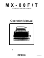
INTRODUCTION
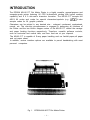
The EPSON MX-80 F/T Dot Matrix Printer is a highly versatile, general-purpose and
computer-grade printer featuring 80 CPS bi-directional printing with logical seeking
capability and 9 X 9 dot-matrix character formation. The MX-80 F/T accepts the
ASCII 96 codes and codes for special characters/symbols (e.g.. b; C 2). It also
accepts codes for 64 graphic patterns.
Characters can be printed in any desired size - enlarged, condensed, emphasized,
normal, etc. The one-chip microprocessor is engaged in performing all functions of
the Printer and the two built-in stepper motors of the MX-80 F/T control the carriage
and paper feeding functions respectively. Therefore, versatile software controls,
such as horizontal and vertical tabs, and form feed are at your disposal.
The MX-80 F/T is capable of S-way paper handling such as fanfold paper,roll paper
and cut paper sheet.
In addition, various interface options are available to permit handshaking with most
personal computers.
Fig. 1.
EPSON MX-80 F/T Dot Matrix Printer
- 1 -
INSTALLATION
1. Contents of Carton
The MX-80 F/T and standard accessories are as shown in Fig. 2. Upon unpacking, if you notice any listed contents missing or evident damage. contact the
store where you purchased the MX-80 F/T as soon as possible.
1
Power Cord (European Type) Operation Manual
MX-80 F/T Dot Matrix Printer
1. MX-80 F/T
2. Separator
3. Cartridge Ribbon
1
1
4. Power Cord (Only European Type 220/240V)
5. MX-80 F/T Operation Manual
1
1 ]
1
Fig. 2 Contents of Carton
- 2 -
2. Unpacking
Before removing the MX-80 F/T from the carton, check the box for evidence of
shipping damage or mishandling. If such evidence is present, notify the carrier
immediately.
2.1. Unpacking steps
Unpacking steps are as follows:
STEP 1. Open the carton.
STEP 2. Remove accessories.
STEP 3. Remove the MX-80 F/T by holding its underside and lifting it straight
up with the packing material attached.
STEP 4. Place the Printer with the packing material on a table or any other convenient flat surface.
STEP 5. Take off the packing material carefully.
STEP 6. Remove the vinyl cover.
2.2. Repacking steps
Repacking can be carried out by following the above steps in the reverse order.
(Repacking: Shipment for repair, storage, etc.)
NOTE: It is recommended that all original packing materials be saved for reuse in case
the MX-80 F/T requires reshipment in the future.
3. Installation of the Printer
(1) Operating site selection
When installing the MX-80 F/T, observe the following instructions.
(a) Place the Printer on a bench, tabletop or any other convenient flat surface with enough room for the separator in the back of the Printer.
NOTE: Rubber feet are provided to prevent the marring of the surface on
which the MX-80 F/T is placed.
(b) Avoid operating the MX-80 F/T in places where it may be exposed to
direct sunlight or where a great deal of greasy dust exists in the air.
NOTE: Greasy dust may cause the malfunction of the print head.
(c) Connect the power cord to an outlet separated from those connected
to noise-generating equipment, such as large-power motors, refrigerators, etc.
(d) Do not subject the Printer to temperatures below 5°C (4O’F) or above
35°C (95’F) during operation, to sudden changes in temperature, or to
extreme shock.
(e) Avoid use of the Printer in humid locations or in the vicinity of heat
generating sources such as heater, etc.
- 3 -
(2) Removal of protective paper for paper end detector
The MX-80 F/T is provided with a protective paper inserted between the
inner and outer paper guides to protect the paper end detector from
damage due to shocks or vibrations during transportation. Before using the
Printer, be sure to remove this paper. If the MX-80 F/T is to be reshipped.
remember to return it to the original position.
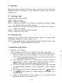
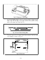
(3) Removal of shipping screws
The purpose of the shipping screws is to protect the MX-80 F/T against any
damage that may be caused by shocks or vibrations during transportation.
Therefore, before operating the MX-80 F/T, remove the screws as described below. (See Fig. 3.)
STEP 1. Open the printer lid.
STEP 2. Remove with a screwdriver, the two shipping screws visible inside
the printer mechanism.
Shipping Screws
Fig. 3 Removal of Shipping Screws
NOTE: Save the two shipping screws for possible future use.
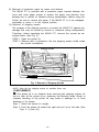
<SUPPLEMENT>
0 If the printer lid is an obstacle when removing the shipping screws, be
sure to take off the printer lid by observing the following steps. Rough or
careless handling of the printer lid may result in damage to. or even
breakage of its hinges.
Step 1. Stand the printer lid upright.
Step 2. Push the printer lid toward the right and pull up its left side. (See
Figs. 4 (1) and (2).)
- 4 -
Printer Lid
(1) Standard
(2) Option
Fig. 4 Removal of Printer Lid
NOTE: The printer lid shown in Fig. 4 (2) is an optional accessory.
- 5 -
4. Cartridge Ribbon Setting
EPSON’s Cartridge Ribbon is compact, long-lasting, and very easy to set and
remove. Furthermore, you have no need to soil your fingers in handling it.
STEP 1. Open the printer lid (or remove it).
STEP 2. Confirm that the scale (paper retainer) is turned toward the platen and
is touching.
STEP 3. Push the cartridge ribbon down and set it on the printer mechanism.
To facilitate the cartridge ribbon setting, be sure to hold the projection
at the center of the cartridge case when pushing the cartridge ribbon
down. (See Fig. 5.)
Fig. 5 Cartridge Ribbon
STEP 4. Put the ribbon between the head nose and the ribbon mask. In this
case, the ribbon can be set easily by hooking it to the edge of the head
nose and turning the ribbon feeding knob of the cartridge case in the
direction of the arrow (i.e., counterclockwise) while depressing the ribbon with a ball-point pen. Then, tension the ribbon by turning the ribbon feeding knob counterclockwise. (See Fig. 6.)
Fig. 6 Cartridge Ribbon Setting
- 6 -
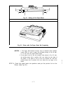
NOTES: 1. Incorrect setting of the ribbon may cause it to come off. (See Fig. 7.)
2. Confirm that the ribbon is neither twisted nor creased and that the
cartridge is set properly.
Ribbon Mask
Incorrect
Fig. 7
Incorrect
Correct
Examples of Correct and Incorrect Ribbon Setting
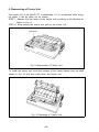
5. Separator Installation
The separator of the Printer contributes to smooth paper feeding. Set the separator by inserting its edge into the two holes located at the rear part of the
paper feeding mechanism. (See Fig. 8.)
Fig. 8 Separator Installation
- 7 -
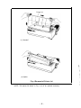
6. Dismounting of Tractor Unit
The tractor unit of the MX-80 F/T is detachable. If it is an obstacle when using
roll paper, it can be taken out as follows;
STEP 1. Release the lock levers of the tractor unit by pulling in the direction as
shown in Fig. 9.
STEP 2. Keep pulling the levers and pull up the tractor unit
Lock lever
Fig. 9 Dismounting of Tractor Unit
To install the tractor unit, hook the notches of the tractor frames onto the shaft
shown in Fig. 10 and then push down the tractor unit.
Fig. 10 Mounting of Tractor Unit
-8-
I
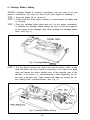
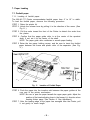
7. Paper Loading
7.1. Fanfold paper
7.1.1. Loading of fanfold paper
The MX-80 F/T Printer accommodates fanfold paper from 4” to 10” in width.
To load the fanfold paper, observe the following procedure.
STEP 1. Raise the printer lid.
STEP 2. Unlock the release lever by pulling it in the direction of the arrow. (See
Fig. 11.)
STEP 3. Pull the scale toward the front of the Printer to detach the scale from
the platen.
STEP 4. Confirm that the paper guide roller is at the center of the sprocket
shaft, If not, set it at the center of the shaft.
NOTE: The paper guide roller contributes to smooth paper feeding.
STEP 5 Raise the two paper holding covers, and be sure to insert the fanfold
paper between the frame and plastic roller of the separator. (See Fig.
11.)
I
1
Scale
Fig. 11
Insertion of Fanfold Paper
STEP 6. Push the paper into the insertion slot between the paper guides at the
rear part of the printer mechanism.
NOTE: Be sure to pass the paper beneath the upper paper guide. Adjust the
position of the head adjusting lever in the forward (+) direction when
inserting thicker paper. (See Section 8. Gap Adjustment.)
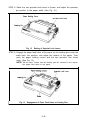
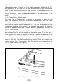
STEP 7. After the leading edge of the paper has emerged from the Printer, pull
it out gently to some length.
- 9 -
STEP 8. Raise the two sprocket lock levers to loosen, and adjust the sprocket
pin position to the paper width. (See Fig. 12.)
Paper Holding Cover
Fig. 12
ket Lock Lever
Raising of Sprocket Lock Levers
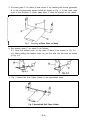
, STEP 9. Engage the paper feed holes of the paper on the feeding pins, push the
scale back into position, and adjust the tension of the paper. Then
push the paper holding covers and the two sprocket lock levers
down. (See Fig. 13.)
NOTE: In this case, confirm that the feeding pins are centered in the respective paper feed holes of the paper.
ocket Lock Lever
Fig. 13
Engagement of Paper Feed Holes on Feeding Pins
-10-
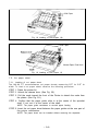
STEP 10. Put the printer lid on the Printer. (See Fig. 14.)
I
Fig. 14
Printer with Fanfold Paper Set Completely
NOTE: When the MX-80 F/T is to be used on a desk or a bench, arrangement
of the fanfold paper in parallel with the MX-80 F/T as shown below
will permit the paper to be folded in an accordion style.
Course of
Paper
Fig. 15: Example of Paper Arrangement
7.1.2. Removal of fanfold paper
To remove the fanfold paper, follow either of the two methods described
below.
(1) To disengage the paper from the paper holding mechanism, pull it forward
out of the Printer.
NOTE: Do not attempt to pull out the paper in the backward direction.
(2) Feed the paper out of the Printer by electrical operation. For this, turn the
Power Switch on and push the Line Feed button. (Details are described
later.1
- 1 1 -
7.1.3. Column layout on fanfold paper
When fanfold paper of from 4” to 10” in width is supplied with the MX-80 F/T,
the graduations on the scale can be used as the indexes of print column positions (1~80). Alignment of the print start position on fanfold paper with the
1st column position at the extreme left of the scale will facilitate column
layout. Accordingly. center the paper by adjusting it to these indexes of the
scale.
7.1.4. Top of form position setting
The term “Top of Form position” is defined as the position in which the first
print line lies on the form, and this position is determined when the power
switch is turned on. Namely, adjust the paper position by the manual paper
feed knob so that the required line position (i.e., the point at which the first line
of the form is desired to be printed) is at the print head level. If, at this point,
power is applied to the Printer, this line position automatically becomes the
Top of Form position.
When printing forms, the matchmarks located on both the sprockets facilitate
the setting of the Top of Form position on the fanfold paper. To set the Top of
Form position, first enter (or preprint) a mark at a position on the edge of the
paper 77 mm above the first print line position of the paper, then align this
mark with the matchmarks on the sprockets by turning the manual paper feed
knob. At this point, turn the Power Switch on and the Printer will recognize this
position as the Top of Form position. Now, the printing can be started from the
Top of Form position. (See Fig. 16.)
In case of feeding one page of fanfold paper by operating the MX-80 F/T by the
input of FF code, the abovementioned adjustment is effective.
-
Matchmark
r
77 mm
Fig. 16 Top of Form Position Setting
7.2. Roll Paper
7.2.1. Roll paper holder
EPSON offers the roll paper holder as an optional accessory for the MX-80 F/T.
See Appendix for the assembly instructions on Roll Paper Holder.
7.2.2. Loading of roll paper
The MX-80 F/T accommodates a roll of single ply paper measuring 8.5f0.12
in. in width with a 1 in. core. To load it, observe the following procedure.
STEP 1. Raise the printer lid.
STEP 2. Unlock the release lever by pulling it in the direction of the arrow. (See
Fig. 17.)
STEP 3. Pull the scale toward the front of the Printer to detach the scale from
the platen. (See Fig. 17.)
STEP 4. Confirm that the paper guide roller is at the center of the sprocket
shaft. If not, set it at the center of the shaft. (See Fig. 17.)
NOTE: The paper guide roller contributes to smooth paper feeding.
STEP 5. Insert the end of the roll paper between the frame and the plastic roller
of the separator. (See Fig. 17.)
STEP 6. Push the paper into the insertion slot between the paper guides at the
rear part of the printer mechanism. (See Fig. 18.)
NOTES: 1. Be sure to pass the paper beneath the upper paper guide.
2. Two-ply roll paper is not recommended for use.
STEP 7. Lock the release lever and push the scale back into position. (See Fig.
19.)
STEP 8. While turning the manual paper feed knob clockwise, confirm that the
paper advances straight up. If not, adjust the inserted paper position
by unlocking the release lever.
STEP 9. Put the printer lid on the Printer.
-13-
Roll Paper
Fig. 18 Loading of Roll Paper (2)
Roll Paper
Manual Paper Feed Knob
Fig. 19 Loading of Roll Paper (3)
7.3. Cut paper sheet
7.3.1. Loading of cut paper sheet
The MX-80 F/T accommodates cut paper sheets measuring 8.3” to 8.5” in
width. To load a cut paper sheet, observe the following procedure.
STEP 1. Raise the printer lid.
STEP 2. Unlock the release lever. (See Fig. 20.)
STEP 3. Pull the scale toward the front of the Printer to detach the scale from
the platen. (See Fig. 20.)
STEP 4. Confirm that the paper guide roller is at the center of the sprocket
shaft. If not, set it at the center of the shaft.
NOTE: The paper guide contributes to smooth paper feeding.
STEP 5. Insert the cut paper sheet between the paper guides at the rear part of
the printer mechanism.
NOTE: The paper sheet can be installed without removing the separator.
-14-
I
Fig. 20 Loading of Cut Paper Sheet
STEP 6. Lock the release lever.
STEP 7. While turning the manual paper feed knob clockwise, confirm that the
paper advances straight up. (See Fig. 21.)
Manual Paper
Feed Knob
Fig. 21
Adjustment of Inserted Paper Position
If not, adjust the inserted paper position as follows:
(a) If the cut paper sheet or form is long enough, unlock the release
lever and align the side edges of the paper as shown in Fig. 22.
- 1 5 -
Fig. 22 Alignment of Side edges
(b) If the cut paper sheet or form is not long enough to align the side
edges, align the top edge of the paper with the form position setting
mark on the tractor unit. (See Fig. 23.)
,
1 i.
-
l/s
I
l/4
I
Fig. 23 Form Position Setting Mark
The print area on the cut paper sheet (when printing it with the tractor
unit installed) is shown in Fig. 24.
210 mm (8.3”)-216 mm (8.5”)
-We
1
28.6 or
30.2 mm,
kzs:.CDE
305 mm
(’ 2”)1 Max.
Fig. 24 Print Area
- 1 6 -
+...-- Letter Size Paper---+
4,
;
rA4SizePaperpf
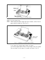
Fig. 25
I
Fig. 26
/4
Setting of Cut Paper Sheet
Printer with Cut Paper Sheet Set Completely
NOTES: 1. The Paper End Detector function may be disabled under software
control (ESC 8; refer to page 39) provided printing is left off within 7.5 mm from the paper bottom edge.
2. If the paper is set on the line marked 1/4as shown in Fig. 25, then
the printing starts from a position 28.6 mm below the top edge of
the paper. If the paper is set on the line marked 1/8. then the
printing starts from a position 30.2 mm below the top edge of the
paper.
STEP 8. Push the scale back into position and put the printer lid on the
Printer. (See Fig. 26.)
- 1 7 -
8. Gap Adjustment
The adjustment of a gap between the head nose and the platen is used to
adjust the printing pressure as well as to suit paper of a different thickness.
(1) Move the head adjusting lever (located on the left frame of the Printer) forward or backward to adjust the gap between the head nose and the platen.
(See Fig. 27.)
Forward: To widen gap.
Backward: To narrow gap.
NOTE: With a thick paper, be sure to widen this gap.
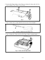
(2) Adjust the position of the head adjusting lever according to the type of
paper to be used.
Paper
Single-leaf paper
Carbon paper sheets
Position of adjusting lever
Set the lever to the 4th step.
Set the lever to the 7th step.
(3) Should printed characters become faint due to the use of the Printer for an
extended period, move the head adjusting lever backward (in the@direction) by one step. (See Fig. 27.)
(4) When a set of carbon paper sheets is used, be sure that no characters are
printed within the area two lines each above and below the perforation.
9. Power Connection
The EPSON MX-80 F/T Dot Matrix Printer is capable of operating on the following three types of AC power.
(1) 115V AC, 60Hz
(2) 220V AC, 50Hz
(3) 240V AC, 50Hz
Before connecting the MX-80 F/T to a power source, make certain of the primary AC rating from the label located on the chassis at the rear of the Printer.
After connection of the Printer to the proper power source and upon application of power to the Printer, “Initialization” will take place in the Printer with
the effects described in “OPERATION” 5.4. If your MX-80 F/T has a primary AC
rating different from the available power source, do not attempt to operate the
Printer. Please obtain a replacement unit with the correct AC rating from the
store where you purchased the MX-80 F/T.
- 1 8 -
Head Adjusting Le
@Backward _ Fotward @
4th step
Head Adjusting Lever
7th step
Fig. 27 Gap Adjustment
-19-
OPERATION
1. Switches and indicators
There are three switches and four indicators (green LED’s) on the control panel
and one power switch on the right side of the Printer case. In this section, panel
operating procedures are covered in sufficient detail for the user to become
familiarized with the Printer. (See Fig. 28 for the control panel.)
Power Switch
Fig. 28
Switches and Indicators on Control Panel ContyPanel
1 .1 Switches
POWER SW: Controls primary AC power to the Printer.
NOTE: Before turning this switch on, check to see if the paper is properly set in the Printer.
Incorrect setting of the paper may prevent the Printer from
operating properly.
ON LINE SW: When this switch is depressed, the Printer enters the ON-LINE
mode and can be utilized in conjunction with a host computer.
Depressing the switch again will set the Printer in the OFF-LINE
mode. The switch does not function while the Printer is actively
engaged in printing. The Printer is automatically placed OFFLINE if the paper supply is exhausted or if a mechanical error
occurs in the Printer.
The operations of the Line Feed and Form Feed switches are
effective only while the Printer is OFF-LINE.
When the ON LINE switch is pushed while data is being received, all data received up to then is printed immediately. This
is helpful to avoid data loss. If data has been transferred into the
print buffer without any print command such as CR, LF or VT
code, no data can be printed out on the paper. However, if the
ON LINE switch is turned off, the data stored in the print buffer
is printed out. Therefore, no data is lost when the Printer
becomes OFF-LINE.
-20-
FF SW:
(Form Feed)
LF SW:
(Line Feed)
When this switch is depressed once, the paper is advanced vertically to the next Top of Form position. This switch must be
depressed while the Printer is OFF-LINE. Otherwise, the form
feed operation will not be carried out.
The Top of Form position is initialized when the POWER switch
is turned on or when INIT signal is applied to the interface connector. Therefore, before turning the POWER switch on to start
operating the Printer, set the paper at the appropriate Top of
Form position. (See “INSTALLATION” 7.1.4.)
The paper advances while this switch is being depressed. The
line spacing for paper advancement is determined by ESC A+n
code (described later). When the POWER switch is on, the line
spacing is initialized at 1/6 inch.
The line feed operation is prohibited while the Printer is actively
engaged in printing.
1.2. Indicators
Illuminates while the Printer is receiving AC power.
POWER:
Illuminates when the Printer is ready to receive data.
READY:
PAPER OUT: Illuminates when the paper supply is near its end.
Illuminates when the Printer is in the ON-LINE mode.
ON LINE:
2. Buzzer
The buzzer is located inside the Printer case, and sounds under the following
conditions.
It sounds for about 3 seconds when the Printer receives BEL
BEL code:
code.
Error status:
It sounds intermittently for about 30 seconds when the Printer
falls into error status.
NOTE: Setting of the DIP switch pin 1-6 (on the control circuit board)
OFF stops the buzzer from sounding under the above conditions.
3. Paper End Detector
When the paper end detector (a reed switch located on the paper guide)
detects that the paper is nearly exhausted, the signals on the interface connector change to the following statuses.
-21-
I
Table 1
Interface Signals in Paper-Out Status
When the Printer falls into paper-out status, the buzzer sounds intermittently
for 30 seconds to alert the operator. After the buzzer stops, paper advancement
can be performed by depressing the LF switch.
After setting new paper in the Printer, depress the ON LINE switch so that the
Printer may resume operation. There is another way to start the Printer again
when it falls into paper-out status. Set new paper in the Printer, and turn the
POWER switch off and on again, or apply the m signal.
In this case, however, all previously established data such as TAB, line spacing,
etc. are erased.
4.
Self-Test
The MX-80 F/T has a self-test (self-diagnostic) function to check the following.
(1) Print head operation and printing quality
(2) Operation of the printer mechanisms (motor, cartridge ribbon mechanism,
belt. etc.)
The self-test function is pre-programmed and can be performed by turning the
POWER switch on while depressing the LF switch. All characters provided by
the internal software are printed out on the paper by this operation.
789: ; ~:=3?@ABCDEFGHIJKLMNOPQRSTUVWXYZC\3~~~~ ‘abed
(=>?@fiBCDEFGHI JKLMNOPQRSTUVWXYZK\l.“. ‘abcde
: i (=>?@ABCDEFGHI JKLMNOPQRSTUVWXYZC\l”_ “abcdef g
; ~~=>?@ABCDEFGHIJKLMNOFQRSTUVWXYZK\l~’~ ‘abcdefgh
NOTES: 1. The self-test function cannot be performed when the printer is out of
paper.
2. To check all interface logic including the interface connector, proceed
as follows:
(a) Connect ACKNLG signal pin No. 10 to STROBE signal pin No. 1 with
a lead wire.
(b) Turn the DIP switch 2-3 (on the control circuit board) ON to effect
auto-line feed.
- 2 2 -
(c) Set the adequate ASCII code data to be printed. To obtain low logic
level signals, connect the data transfer line required for printing (pin
Nos. 2 to 9) to GND level (pin No. 33, etc.)
l Example of printing’?”
“Z”=[5. A]~=(0101 1010)
In this case, connect pin Nos. 2, 4, 7 and 9 to pin No. 33.
5. Construction of MX-80 F/T
The EPSON MX-80 F/T Dot Matrix Printer consists of the following three major
functional blocks.
(1) The model 3310 printer mechanism
(2) Control circuit board
(3) Power circuit
These three blocks are housed in a plastic case and are connected to one
another.
5.1. Printer mechanism
The model 3310 printer mechanism has been developed by Shinshu Seiki with
the technology in the precision and electronic industry fields amassed through
its long association with SEIKO, manufacturer of the world-famous SEIKO
watches.
The printer mechanism contains two stepper motors. One is to move the print
head to the next print column position, and the other is to advance the paper.
(1) Stepper motor for head carriage
The stepper motor for head carriage is controlled under LSI “8041” called
“slave CPU”. The CPU knows the current printing position at any given
time, and the print head is stopped at the last printing position. Then, the
CPU seeks the shortest travel way to the next print line.
This feature and bi-directional printing enable the Printer to perform the
logical seeking function which minimizes the head travel time to the next
print line.
(2) Stepper motor for paper feed
Paper is fed by the stepper motor, like the head carriage. One complete
rotation of the stepper motor corresponds to 1/3 inch paper advance. In
the MX-80 F/T, the operator can select any paper feed length under software control (described in detail later).
(3) Micro print head
The micro print head has 9 dot wires to form 9 X 9 dot matrix characters. 9
wires form more legible characters than those formed by 7 wires. The print
head for the 3310 printer mechanism is quite compact.
-23-
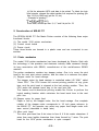
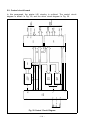
5.2. Control circuit board
In this paragraph, the printer LSI circuitry is outlined. The control circuit
diagram is shown ‘in Fig. 29, and the driver circuit diagram in Fig. 30.
Fig. 29 Control Circuit Diagram
- 2 4 -
9 X 2SD986
HI 0
m
Hz 0
I
H, 0
D
H, 0
1
“s 0
>
H, 0
D
H, 0
m
He 0
D
H9 O-
Fig. 30 Driver Circuit Diagram
-25-
5.3. Power circuit
The power circuit generates 5V DC for the logic circuit, and 24V DC to energize
the solenoids of the print head and two stepper motors.
5.4. Printer initialization
Printer initialization is accomplished in either of the two ways described below.
(1) Initialization takes place automatically each time the primary AC power
source is interrupted and reapplied (i.e.. by turning the Power Switch off
and on).
(2) Initialization may be initiated remotely by activating the INIT signal to the
parallel interface connector. This line should be driven by a TTL driver or its
equivalent.
The minimum reset pulse width is 50 psec at the receiving terminal. Upon
application of the initialization signal, the following sequence of events
take place in the Printer.
(a) The print head returns to its home position.
(b) The Printer is automatically placed ON-LINE, unless it is out of paper.
(c) The print buffer is cleared.
(d) The line spacing is set at 1/6 inch.
(e) The form length per page is set to 66 or 72 lines.
NOTE: The form length of 72 lines per page is applicable to only the version
*marked with identifier code “M72” on the rear side of the lower case
of the Printer.
(f) Any stored vertical or horizontal tab stop positions are cleared.
(g) The character print-width logic is reset to the normal state.
- 2 6 -
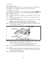
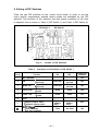
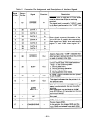
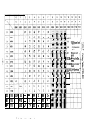
8. Setting of DIP Switches
There are two DIP switches on the control circuit board. In order to suit the
user’s specific requirements, desired control modes are selectable by the DIP
switches. The functions of the switches and their preset conditions at the time
of shipment are as shown in Table 2 (DIP Switch 1) and Table 3 (DIP Switch 2).
DIP Switch 2
Fig. 31
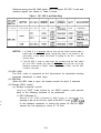
Table 2
1
Not applicable
2
CR
3
Buffer full
4
Cancel code
5
6
8
Location of DIP Switches
Functions and Conditions of DIP Switch 1
ON
Function
Pin No.
7
DIP Switch 1
OFF
Factory-set
Condition
ON
ON
Print only
Print &
line feed
Print &
line feed
Valid
Invalid
Invalid
Valid
OFF
Delete code
Valid
Invalid
Invalid
Valid
ON
Error
Buzzer
Sounds
Does not sound
ON
Japanese
syllabary
select
Graphic
patterns
select
OFF
Fixed
Not fixed
ON
Print
{ Print
Print
{ Print
& Line Feed
only
Print only
& Line Feed
only
Character generator
Graphic patterns select
t Japanese syllabary select
SLCtlN rig&
Fixed internally
Not fixed internally
- 2 7 -
ON
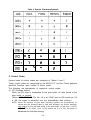
Table 3
Pin
No.
Function
1
Selectors
of
fSee Table 8)
2
3
4
Functions and Conditions of DIP Switch 2
AUTO FEED
XT signal
Coding table
select
special
characters/symbols
Fixed internally
1 Not fixed internally
TRS80
Standard
ON
OFF
Factory-set
Condition
-
-
ON
Fixed
Not
fixed
OFF
Standard
OFF
TRS-8@
ON
NOTE: When DIP Switch pin 2-4 is set to the “ON” position (for TRS-80 mode), all the
other pins of the DIP switches 1 and 2 will not function irrespective of these
ON/OFF positions.
Table 4
I
Special Characters/Symbols Available for Selection
(using DIP Switch Pins 2-1 and 2-2)
SW2-1
SW 2-2
ON
ON
OFF
ON
OFF
1
Country
U.S.A.
OFF
France
ON
Germany
OFF
England
I
7. Parallel Interface
/
The MX-80 F/T includes a parallel interface as the standard equipment, and
this paragraph describes the parallel interface.
(1) Specifications
(a) Data transfer rate: 1000 CPS (max.)
(b) Synchronization:
By externally supplied STROBE pulses.
(c) Handshaking:
By ACKNLG or BUSY signals.
(d) Logic level:
Input data and all interface control signals are
compatible with the TTL level.
(2) Connector
Plug: 57-30360 (AMPHENOL)
It is recommended that interface cables be kept as short as possible.
(3) Connector pin assignment and descriptions of signals.
Connector pin assignment and descriptions of respective interface signals
are provided in Table 5.
- 2 8 -
Table 5
Connector Pin Assignment and Descriptions of Interface Signals
STROBE pulse to read data in. Pulse width
These signals represent information of the
1st to 8th bits of parallel data respectively.
Each signal is at “HIGH” level when data is
logical “1” and “LOW” when logical “0”.
A “HIGH” signal indicates that the printer
(The signal level can be fixed to “LOW”
-29-
Table 5
(cont.)
-
Return
Signal
Pin No. ! Pin No. I
18
9 to30
-
31
Signal
Description
IDirection
-
NC
-
GND
TWISTED-PAIR RETURN signal GND level.
lNlT
When the level of this signal becomes
“LOW”, the printer controller is reset to its
initial state and the print buffer is cleared.
This signal is normally at “HIGH” level, and
its pulse width must be more than 56~s at
the receiving terminal.
-
Not used.
In
--
32
ERROR
out
-
33
-
GND
34
-
NC
The level of this signal becomes “LOW”
when the printer is in 1. PAPER END state
2. OFF-LINE state
3. Error state
Same as with Pin Nos. 19 to 30.
Not used.
35
Pulled up to +5V through 4.7KD resistance.
36
Data entry to the printer is possible only
when the level of this signal is “LOW”.
(Internal fixing can be carried out with DIP
SW 1-8. The condition at the time of
shipment is set “LOW’ for this signal.)
-
SLCT IN
In
1
NOTES: 1. “Direction” refers to the direction of signal flow as viewed from the
printer.
2. “Return” denotes “TWISTED PAIR RETURN” and is to be connected at
signal ground level.
As to the wiring for the interface, be sure to use a twisted-pair cable for
each signal and never fail to complete connection on the Return side.
To prevent noise effectively, these cables should be shielded and connected to the chassis of the host computer and the printer, respectively.
3. All interface conditions are based on TTL level. Both the rise and fall
times of each signal must be less than 0.2 /.Ls.
4. Data transfer must not be carried out by ignoring the ACKNLG or BUSY
signal. (Data transfer to this printer can be carried out only after confirming the ACKNLG signal or when the level of the BUSY signal is
“LOW”.)
- 3 0 -
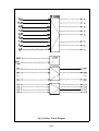
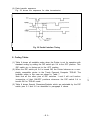
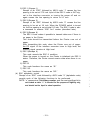
(4) Data transfer sequence
Fig. 32 shows the sequence for data transmission.
r
Fig. 32 Parallel Interface Timing
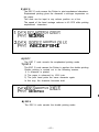
8. Coding Tables
(1) Table 6 shows all available codes when the Printer is set for operation with
standard coding by setting the DIP switch pin 2-4 to the OFF position. This
DIP switch pin is factory-set to the OFF position.
(2) When the DIP switch pin 2-4 is turned ON, the Printer behaves as a completely compatible printer to the Tandy Personal Computer TRS-80. The
available codes in this case are shown in Table 7.
Note that all the other pins of DIP switches 1 and 2 will not function
irrespective of their ON/OFF positions whenever the DIP switch 2-4 is
turned ON for TRS-80 mode.
(3) Table 8 shows Special Characters/Symbols which are selectable by the DIP
switch pins 2-1 and 2-2 as described in paragraph 6 above.
-31-
8
1000
9
1001
HT
A
1010
LF
B
1011
VT
CAN
ESC
(
8
H
X
)
5
9
:
I
Y
+
;
K
J
h
i
Z
t
x
CAN
Y
j
HT
z
k
LF
C
VT
I
L
=
1
\
i
M
3
m
)
CR
n
*
so
--0
DEL
SI
L
D
1101
CR
E
1110
so
.
>
N
F
1111
SI
/
?
0
..x
-
ESC
1
’
I
p
: 16.5 charalinch
-ESC 6 :
-ESC 8 :
-ESC A :
.ESC B :
5 charalinch
print
6 lines/inch line
feed
i
8 lines/inch line
feed
1
Long line mode
1
Short line mode
I
ti
D
1101
E
1110
F
1111
CR
-
=
M
3
m
RS
.
>
N
.+
n
*
us
/
?
0
-
0
DEL
GS
Table 8 Special Characters/Symbols
[781~
[7c1
1
{
I-I
[7D1~
[7E]
H
f
cl
6
I
I
}
6
ii
j
”
P
-
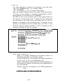
9. Control Codes
Various kinds of control codes are contained in Tables 6 and 7.
These control codes are recognized by the MX-80 F/T, and the Printer performs
specified functions upon receipt of these codes.
The following are descriptions of respective control codes.
(1) CR (Carriage Return)
When the CR code is transmitted to the print buffer, all data stored in the
print buffer is printed.
(When AUTO FEED XT (Pin No. 14) is at “LOW” level or DIP switch pin 2-2
is ON. the paper is advanced one line automatically after printing.)
NOTE: When 80 columns of print data (including spaces)
ceived and the following data is valid and printable,
cally begins to print the data stored in the print buffer.
FEED XT is at “LOW” level or DIP switch pin 2-3
advanced one line after printing.
- 3 4 -
are continuously rethe Printer automatiIn this case, if AUTO
is ON, the paper is
(2) LF (Line Feed)
When the LF code is input, all data in the print buffer is printed and the
paper is advanced one line.
NOTE: If no data precedes the LF code, or if all preceding data is “SPACE”, only
paper feeding is performed.
For example, if the data is transferred in the order of DATA-+CR+ LF.
DATA will be printed by the CR code, and when the Printer receives the LF
code, it only carries out one line feed.
(3) VT (Vertical Tab)
When the VT code is input, all data preceding this code is printed. And the
paper is advanced to the line position set by “ESC B” (described later.) If no
vertical tab position is set by ESC B, the VT code behaves like the LF code.
Therefore, the paper is advanced one line after printing.
(4) FF (Form Feed)
The FF code carries out the printing of all data stored in the print buffer and
advances the paper to the next predetermined Top of Form position. T h e
Top of Form is determined when the POWER switch is turned on or the l@j’i=i
signal is applied.
If the form length per page is not set by “ESC C+n,” it is regarded as 66 or
72 lines.
NOTE: The form length of 72 lines per page is applicable to only the version
marked with identifier code “M72” on the rear side of the lower case of the
Printer.
This code always initializes the printing of the data stored in the print
buffer.
(5) SO (Shift Out)
When the SO code is input, all data that follows it in the same line will be
printed out in enlarged (double width) characters. This code is cancelled by
the printing operation or the input of “DC 4” code and can be input at any
column position on a line. Therefore, normal size and enlarged characters
can be mixed on the same line.
1. [DATA]
[PRINT]
2. [DATA]
PRINT1
ABC m DEF -1 GHI jCRi m
UBCOFIFGHI
I
ABC0 m EFGH (CRI B IJKL (so( MNOP (CR1 ml
AbCDEF’GH
I JKLMNOF
-35-
(6) SI (Shift In)
When the SI code is input, all data that follows it will be printed out in condensed characters. This code is cancelled by the input of “DC 2” code. The
SI code can be input at any column position on a line, but all characters/
symbols on the line containing SI code are printed out in condensed
characters.
When printing condensed characters, the data capacity of the print buffer
will become 132 columns per line.
When the SO code is received after the input of the SI code, condensed
enlarged characters (double width of condensed characters) can be
printed. This condition is cancelled by “DC 4” code, and the character size
returns to “condensed.”
1. [DATA]
[PRINT]
2. [DATA]
[PRINTI
q
ABCDEFGHIJKL
m m
ABCDEFGHI JKL
Ax a DEF Isb] GHIJKL (CRI (LF]
fiBCDEFGH1
,YKL
(7) DC 4 (Device Control 4)
The DC 4 code cancels the SO mode.
[DATA]
[PRINT]
m ABCDEF m GHI a JKL (CRI m
ABCDEFG H I JKL
(8) DC 2 (Device Control 2)
The DC 2 code cancels the SI mode.
[DATA]
[PRINT]
m ABCDEF m GHI lCRj m m JKLMN m m
ABCDEFG H I
J t:::LMN
(9) HT (Horizontal Tab)
The HT code carries out the horizontal tabulation.
If there is no tab position set, this code is ignored. The tab stop positions
are set by “ESC D+n” (described later).
-36-
(10) CAN (Cancel)
Upon the input of the CAN code, all data previously stored in the print
buffer is cancelled.
Therefore, this code is regarded as the print buffer clear command. This
code clears the print buffer, but control codes (excluding the SO code) are
still valid even if the CAN code is transferred.
The validity or invalidity of the CAN code is selectable by the DIP switch
pin l-4 on the control circuit board.
(11) DEL (Delete)
This code functions the same as the CAN code.
The validity or invalidity of the DEL code is selectable by the DIP switch
pin 1-5 on the control circuit board.
(12) DC 1 (Device Control 1)
The DC 1 code places the Printer in the Selected state.
With the Printer is in the Selected state, if the DC 1 code is input during
data transfer, all data stored before the DC 1 code is ignored.
(13) DC 3 (Device Control 3)
The DC 3 code places the Printer in the Deselected state. In other words, it
disables the Printer to receive data. Once the Printer is put in the
Deselected state by the DC 3 code, the Printer will not revert to the
Selected state unless the DC 1 code is input again.
NOTE: When the DC 1 and DC 3 codes are used, DIP switch pin l-8 should be in
the “OFF” position.
1. [DATA]
[PRINT]
2. [DATA]
[PRINT]
m AAAAA a BBBBB m CCCCC a m
AAAcIAccccc
AAAAA
B BBBBB
m CCCCC
bEBBb
- 3 7 -
m m m
Relations among the ON LINE switch, SLCT IN signal, DC l/DC 3 code and
interface signals are shown in Table 9 below.
Table 9
DC 1/DC 3 and Data Entry
NOTES: 1. In Table 9, it is assumed that as soon as the Printer receives data. it
sends back the ACKNLG signal, though this data is not stored in the
print buffer. In this status, the Printer is waiting for the DC 1 code for
normal entry.
2. The DC l/DC 3 code is valid under the condition that the DIP switch
pin l-8 is OFF, namely, the level of SLCT IN at the pin No. 36 of the
interface connector is “HIGH.” When SLCT IN is “LOW,” the DC l/DC
3 code is not valid.
(14) NUL (Null)
The NUL code is regarded as the termination for tabulation setting
sequence (described in detail later).
(15) BEL(Bell)
When the BEL code is input, the buzzer sounds for about 3 seconds.
(16) Escape (ESC) control
(a) Escape numerical control
Input of an “ESC” code followed by an ASCII numeric code permits
each of the following functions to be performed.
1) ESC 0(Escape 0)
Receipt of an “ESC” followed by ASCII code “0” causes the line
spacing to be set at 1/8 inch. Input of the ESC 2 code ormsignal
to the interface connector or turning the power off and on again
causes the line spacing to return to 1/6 inch.
-38-
2) ESC 1 (Escape 1)
Receipt of an “ESC” followed by ASCII code “1” causes the line
spacing to be set at 7/72 inch. Input of the ESC 2 code or INIT signal to the interface connector or turning the power off and on
again causes the line spacing to return to l/6 inch.
3) ESC 2(Escape 2)
Receipt of an “ESC” followed by ASCII code “2” causes the line
spacing to be set at 1/6 inch. When the POWER switch is turned
on, the line spacing is set at initial 1/6 inch. The ESC 2 code is also
a command to execute “ESC A+n” modes (described later).
4) ESC 8(Escape 8)
The ESC 8 code makes it possible to transmit data even if there is
no paper in the Printer.
This code should be transmitted before the Printer runs out of
paper.
After transmitting this code, when the Printer runs out of paper,
the PE signal of the interface connector turns to High level; the
ERROR signal remains at High level.
5) ESC 9(Escape 9)
This code cancels the ESC 8 condition.
When the power is turned on, the Printer is initialized into ESC 9
status. Therefore, the Printer cannot receive data when there is no
paper.
6) ESC SI
This code functions the same as “SI.”
7) ESC SO
This code functions the same as “SO.”
(b) ESC alphabetic control
Receipt of an “ESC” code followed by ASCII code “X” (alphabetic code)
permits each of the following functions to be performed.
NOTE: “n” represents a 7-bit binary number, and the most significant bit is
not treated as data. “+” is inserted for the purpose of legibility only,
and should not be input in actual operation.
-39-
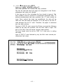
1) ESC A+n
This code specifies the amount of line spacing in the Line Feed.
1 <<n > lo<85 (Decimal): “n” is, a binary number.
“n”=1 is equivalent to 1/72 inch paper advancement.
Since the distance between any two dot wires of the print head is
1/72 inch, any line spacing in increments proportional to the distance between the dot wires can be established.
The ESC A code is the command only to store spacing data into
the memory. In other words, even if spacing data was transferred
into the memory, the Printer does not actually carry out the line
spacing in accordance with the spacing data. To execute the line
spacing in accordance with the stored data, the ESC 2 code
should be followed. Namely, the ESC 2 code is considered as the
execution command for the line spacing.
[DATA]
[PRINT]
AAAAAAA
m /LFI BBBBBBB
jCRj
m jm
CCCCCCC
a m DDDDDDD (ESC1 (CR] m
EEEEEEE
m
[LFI
FFFFFFF
m
B
kr%%M#r
BBE~EmBEl I. 116 inch = 12 steps/72
ccccccc
DDDDDDI)
1 I3 inch = 24 steps/72
EEEEEEE
NOTE: <How to input “n”>
When “n” is actually transferred to the Printer as data, it is
transferred in the form of a 7-bit binary number.
In case of “ESC A+24”, actual output to the Printer is performed
as <1B> H <41> H <18> H in hexadecimal code.
Keep in mind that the method of input from the keyboard of a
host computer is different, for which refer to the specifications of
your host computer.
*Example: Input from the keyboard of the TRS-80 personal computer.
[LPRINT CHR$(27); CHR$(65); CHR$(24)]
- 4 0 -
2 ) E S C B+nl+n2+. +nk+NUL
(ld<n>lo<66,1dkd64,nkdnk+l)
This code specifies the vertical tab stop positions.
The first 64 valid tab stops per page are recognized in the Printer;
subsequent tab stops are ignored.
A tab stop set at a line exceeding the form length is ignored. Tab
stop numbers must be received in incremental numerical order. To
execute predetermined tab stop positions, the VT code should be
input. Once vertical tab stops are established, the data will be
valid until new tab stops are specified. If no tab stop is set, the VT
code behaves like the LF code. Therefore, the paper is advanced
one line after printing.
Receipt of “ESC B” code causes the Printer to accept the following
codes as tab stop line numbers until the NUL code is input. The
lack of the NUL code will cause incorrect data printout.
The form length must be set by “ESC C+n” code prior to setting
tab stops.
Input of “ESC 8” code followed by only the NUL code cancels predetermined tab stops.
[DATA]
[PRINT]
(ESC/ <4>H <6>~ <A>H m
AAAAAAA m BBBBBBB lm CCCCCCC /VTI DDDDDDD
C?li?lAUUfW
1st line
BBBHBE(E! . . . 4th lines
CCCCCCC
6th
lines
DDDDDDD . . . . 10th lines
-41-
3) ESC C+n (ld<n>1&66)
This code specifies the form length per page.
The form length is determined by the number of lines (=“n”). The
amount of a line spacing at this point is a predetermined numerical value by “ESC A+n.” When the form length is not programmed, one page is assumed as 66 or 72 lines. Prior to setting the
vertical tab position, the form length should be set.
4 ) E S C D+nl+nz+. +nk+NUL
(19<n>lo9127. ksl12)
This code specifies the horizontal tab stop positions. The first 112
tab stops per line are recognized in the Printer, and subsequent
tab stops are ignored. Tab stop numbers must be received in
incremental numerical order.
If a tab stop position of higher value than 80 is received in normal
character printing mode, all horizontal tab functions after 80 columns are ignored.
To execute tab stop positions, the HT code should be input. The
HT code is ignored when the horizontal tab position has not been
programmed.
The NUL code should be input as the command for the termination of the tab set sequence, and the lack of this code will cause
incorrect data printout.
1.
Incase of 5th. 10th and 21st columns.
(DATA1
-1 <5>~ <A>H <15>~m
ABC m DEF m GHI m JKL
!EiJm
[PRINT]
2.
UBC
DEF
GHI
J K L.
In case of lack of stop position.
I DATA1
[PRINT]
[e:g <5>H <A>H m ABC m DEF m GHI JHT] JKL a a
ABC
DEF
GHIJKL
3. In case of character data transferring over next tab stop.
I DATA1
[PRINT)
~ <5>H <A>H <15>~ m AECDEF m GHI m JKL /=I pj
AEKDEF
J KL
GHI
4. In case of transferring two HT codes at a time.
[DATAI
m <5>H <A>H <l5>H
m ABED IHT] pm m EFGH
/EKJm
LPR INTI
AEtCD
EFGH
-42-
5) ESC E
The ESC E code causes the Printer to print emphasized characters.
Emphasized printing gives the character a stronger impression on
the paper.
This code can be input in any column position on a line.
The speed of the head carriage reduces to 40 CPS while printing
emphasized characters.
1. [DATA]
PRINT1
2. [DATA]
[PRINT]
lm ABCDEFGHI
(CR1
m
EIBCDEFGHI
m -1 ABCDEFGHI
m m
FIBCDEFGH I
6) ESC F
The ESC F code cancels the emphasized printing mode.
7) ESC G
The ESC G code causes the Printer to perform the double printing.
Double printing is carried out in the following manner.
1) A character is printed.
2) The paper is advanced by 1/216 inch.
3) The print head prints the same character again.
In this way, the character becomes bold.
[DATA]
PRINT1
(ESC]
ABCDEFGHl
(CRI
m
ABCDEFGHI
I
8) ESC H
The ESC H code cancels the double printing mode.
-43-
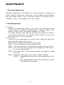
MAINTENANCE
1. Preventive Maintenance
Preventive maintenance for the MX-80 F/T consists basically of cleaning. The
Printer should be cleaned with a soft brush to remove paper dust and particles
after every three months of use. The exterior surface of the Printer can be
cleaned by using a mild detergent and water solution.
2. Parts Replacement
(1) General
Owing to the sophisticated nature of the circuitry and mechanisms utilized
in the MX-80 F/T, operator’s troubleshooting is logically obliged to be
limited to certain easily recognizable symptoms and cures.
If a Printer malfunction other than the print head unit should occur which is
not covered in this section, the operator should contact the store from
which the MX-80 F/T was purchased.
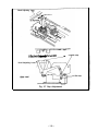
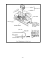
(2) Print head
In case of a print head trouble or a worn dot wire, replace the print head
unit as described below. (See Fig. 33.)
NOTE: Be sure to replace the print head after it has cooled.
STEP 1. Take off the printer lid and cartridge ribbon.
STEP 2. Turn the head lock lever clockwise and remove the print head.
STEP 3. Pull the head cable out straight while steadying the head connector on the terminal board.
STEP 4. Put a new head on the carriage assembly and replace the head
lock lever.
STEP 5. Insert the head cable into the head connector carefully.
NOTES: 1. Inadequate connection may cause malfunctioning of the
head.
2. The carriage assembly should not be moved without the print
head mounted on the carriage.
-44-
Head
Print Head Unit
Cable !
Terminal Board
/
Head Lock
Head Connector
‘Be sure to hold this
connector firmly to
pull the head cable
out straight.
(Side View)
‘Take hold of the
cable at the point
ijjdicated by arrows
e and apply force in
either of the directions indicated by
arrow M to push in
or pull out the had
cable.
Fig. 33 Replacement of Print Head
-45-
SPECIFICATIONS
Serial impact dot matrix
(1) PRINT METHOD:
(2) PRINT SPEED:
80 CPS
Bidirectional with logical seeking
(3) PRINT DIRECTION:
(4) NUMBER OF PINS IN
HEAD:
9
(5) LINE SPACING:
4.23 mm (1/6”) or programmable
(6) PRINTING CHARACTERISTICS
Matrix:
9x9
Full 96-character ASCII with descenders. plus 9
Character Set:
international characters/symbols
64 block characters
Graphic Character:
(7) PRINTING SIZES
Maximum
characters
Characters
per line
per inch
80
Normal:
10
40
Enlarged:
5
132
Condensed:
16.5
66
8.25
Condensed Enlarged:
(8) MEDIA HANDLING
Friction feed or adjustable sprocket feed
Paper Feed:
selectable manually
Paper Width Range
101.6 mm (4”) to 254 mm (10”)
Fanfold paper:
215.9
mm (8.5”)*3 mm (0.12”)
Roll paper:
Cut paper sheet:
210 mm (8.3”) to 216 mm (8.5”)
Paper Path:
Rear
(9) INTERFACES
Centronics-style 8-bit Parallel
Standard:
Optional:
RS232. IEEE 488
(10) INKED RIBBON
Color:
Black
Exclusive cartridge
Type :
3 million characters
Life Expectancy:
5 x 10s lines (excluding print head)
(11) MCBF:
(12) ENVIRONMENTAL CONDITIONS
Operating Temperature
Range:
5 to 35°C (41 to 95°F)
10 to 80% non-condensing
Operating Humidity:
-46-
SPECIFICATIONS (continued)
(13) POWER REQUIREMENT
Voltage:
115V. 60 Hz
220/240V, 50 Hz
Current:
1 Amp maximum
Power Consumption:
100 VA maximum
(14) PHYSICAL CHARACTERISTICS
Height:
133 mm (5.2”)
W idth:
374 mm (14.7”)
Depth:
305 mm (12.0”)
7.0 kg (15.4 Ibs.)
Weight:
I
Specifications subject to change without notice.
-47-
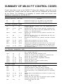
SUMMARY OF MX-80 F/T CONTROL CODES
Control code data is sent to the MX-80 F/T along with character code data via the
input data lines. Control codes are sent as data, and are interpreted as instructions
by the Printer. The following is a summary of control codes and control code
sequences recognized by the MX-80 F/T.
(1) Print action codes
Mnemonic Decimal
CR
LF
13
10
Function
Hex. code
0D
0A
Performs the printing of a line stored in the print buffer.
Performs the printing and advances the paper one line.
(2) Paper movement codes
FF
12
0C
ESC C
HT
27. 67
9
1B,43
09
ESC D
27,68
1B.44
VT
OB
11
ESC B
27. 66
1B. 42
ESC 0
ESC 1
ESC 2
27. 48
27. 49
27. 50
1B. 30
1B. 31
1B. 32
ESC A
27. 65
1B. 41
Advances the paper vertically to the next predetermined Top
of Form position.
Specifies the form length per page. Execution command IS FF.
Advances the print head to the next predetermined tab stop
position in a horizontal direction.
Specifies the horizontal tab stop positions. Execution command is HT.
Advances the paper to the next predetermined tab stop position in a vertical direction.
Specifies the vertical tab stop positions. Execution command
is VT.
Causes the line spacing to be set at 1/8 inch.
Causes the line spacing to be set at 7/72 inch.
Causes the line spacing to be set at 1/6 inch. This code is also
a command to execute the predetermined line spacing mode.
Specifies the amount of line spacing in the Line Feed. Execution command is ESC 2.
(3) Character designation code
14
Instructs
OE
SO
DC 4
SI
DC 2
ESC E
ESC F
ESC G
ESC H
20
15
18
27.
27.
27.
27.
69
70
71
72
14
OF
12
1B. 45
1B. 46
1B. 47
1B .48
the Printer to print subsequently received characters in double width size.
Cancels the SO (enlarged character) mode.
Instructs the Printer to print characters in condensed size.
Cancels the SI (condensed character) mode
Causes the Printer to print emphasized characters.
Cancels the ESC E mode.
Causes the Printer to perform double printing.
Cancels the ESC G mode.
(4) Other codes
NUL
BEL
DC 1
DC 3
0
7
17
19
00
07
11
13
ESC 8
27, 56
1B. 38
ESC 9
CAN
27. 57
24
1B. 39
18
DEL
127
7F
Terminates the tabulation setting sequence.
Causes the buzzer to sound for about 3 seconds.
Places the Printer in the selected (data receivable) state.
Places the Printer in the deselected (data not receivable)
state.
Permits data to be transmitted even If there is no paper in the
Printer.
Cancels the ESC B condition.
Deletes from the print buffer all previously entered printable
characters. (Print buffer clear command)
Functions the same as ‘CAN’.
-48-
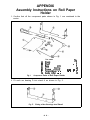
APPENDIX
Assembly Instructions on Roll Paper
Holder
1. Confirm that all the component parts shown in Fig. 1 are contained in the
carton.
A
B
C
D
E
F
G
Fig. 1
Part name
Stand.
Shaft
Base
plate
Arc
bearing.
Screw
grommet.
Tension lever. . .
Guide
roller
. .
Component Parts of Roll Paper Holder
2. Fit each arc bearing D into stand A as shown in Fig. 2.
Fig. 2
Fitting of Arc Bearings into Stand
- 4 9 -
QW
1
1
1
2
.. 2
. 1
2
.
. . .
. .
3. Put base plate C on stand A and secure it by inserting two screw grommets
E to the corresponding square holes as shown in Fig. 3. In this case, take
note of the direction in which base plate C must be placed on the stand.
I
Fig. 3
Mounting of Base Plate on Stand
4. Set tension lever F on stand A as follows:
4-1: Hook the tension lever on the nose of stand A as shown in Fig. 4-1.
4-2: While pulling the tension lever up, put the wire into the hole as shown
in Fig. 4-2.
Fig. 4-1
5. Fig. 5 shows the Roll Paper Holder in the assembled state.
Fig. 5 Assembled Roll Paper Holder
-50-
6. Set the Roll Paper Holder to the Printer by aligning the base plate with the
knots located at the bottom of the printer.
Fig. 6
7. Fig. 7 shows how to insert shaft B into the core of the roll paper.
I
I
Fig. 7
Insertion of Shaft B into Roll Paper Core
8. Fig. 8 shows the Printer with the Roll Paper Holder mounted thereto.
Fig. 8
Printer with Roll Paper Holder
-51-
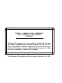
FEDERAL COMMUNICATIONS COMMISSION
RADIO FREQUENCY INTERFERENCE
STATEMENT
“Warning: This equipment has been certified to comply with the limits
for a Class B computing device, pursuant to Subpart J of Part 15 of FCC
Rules. Only computers certified to comply with the Class B limits may be
attached to this printer. Operation with non-certified computers is likely
to result in interference to radio and TV reception.”
This statement will be applied only for the printers marketed in the U.S.A.
EPSON
SHINSHU SEIKI CO., LTD
EPSON OVERSEAS MARKETING LOCATIONS
EPSON AMERICA, INC. (L.A.)
EPSON AMERICA, INC. (N.Y.)
23844 Hawthorne Blvd.,
Torrance, Calif. 90505
Phone: (213)378-2220
Telex: (25)9103447390
98 Cutter Mill Road
Great Neck, New York
Phone: (516)487-0660
Telex: (25)510223-0743
EPSON DEUTSCHLAND GMBH
EPSON U.K. LTD.
Am Seestern 24
4000 Dtisseldorf 11,
F.R. Germany
Phone:
0211-593080
Sherwood House 176 Northolt Road
South Harrow
HA2 OEB U.K.
Phone: (01) 422-5612 Telex: 8814169
Telex:
(41)8584786
PRINTED IN JAPAN
81.02-10