1
To our customers,
Old Company Name in Catalogs and Other Documents
On April 1st, 2010, NEC Electronics Corporation merged with Renesas Technology
Corporation, and Renesas Electronics Corporation took over all the business of both
companies. Therefore, although the old company name remains in this document, it is a valid
Renesas Electronics document. We appreciate your understanding.
Renesas Electronics website: http://www.renesas.com
April 1st, 2010
Renesas Electronics Corporation
Issued by: Renesas Electronics Corporation (http://www.renesas.com)
Send any inquiries to http://www.renesas.com/inquiry.
Notice
1.
2.
3.
4.
5.
6.
7.
All information included in this document is current as of the date this document is issued. Such information, however, is
subject to change without any prior notice. Before purchasing or using any Renesas Electronics products listed herein, please
confirm the latest product information with a Renesas Electronics sales office. Also, please pay regular and careful attention to
additional and different information to be disclosed by Renesas Electronics such as that disclosed through our website.
Renesas Electronics does not assume any liability for infringement of patents, copyrights, or other intellectual property rights
of third parties by or arising from the use of Renesas Electronics products or technical information described in this document.
No license, express, implied or otherwise, is granted hereby under any patents, copyrights or other intellectual property rights
of Renesas Electronics or others.
You should not alter, modify, copy, or otherwise misappropriate any Renesas Electronics product, whether in whole or in part.
Descriptions of circuits, software and other related information in this document are provided only to illustrate the operation of
semiconductor products and application examples. You are fully responsible for the incorporation of these circuits, software,
and information in the design of your equipment. Renesas Electronics assumes no responsibility for any losses incurred by
you or third parties arising from the use of these circuits, software, or information.
When exporting the products or technology described in this document, you should comply with the applicable export control
laws and regulations and follow the procedures required by such laws and regulations. You should not use Renesas
Electronics products or the technology described in this document for any purpose relating to military applications or use by
the military, including but not limited to the development of weapons of mass destruction. Renesas Electronics products and
technology may not be used for or incorporated into any products or systems whose manufacture, use, or sale is prohibited
under any applicable domestic or foreign laws or regulations.
Renesas Electronics has used reasonable care in preparing the information included in this document, but Renesas Electronics
does not warrant that such information is error free. Renesas Electronics assumes no liability whatsoever for any damages
incurred by you resulting from errors in or omissions from the information included herein.
Renesas Electronics products are classified according to the following three quality grades: “Standard”, “High Quality”, and
“Specific”. The recommended applications for each Renesas Electronics product depends on the product’s quality grade, as
indicated below. You must check the quality grade of each Renesas Electronics product before using it in a particular
application. You may not use any Renesas Electronics product for any application categorized as “Specific” without the prior
written consent of Renesas Electronics. Further, you may not use any Renesas Electronics product for any application for
which it is not intended without the prior written consent of Renesas Electronics. Renesas Electronics shall not be in any way
liable for any damages or losses incurred by you or third parties arising from the use of any Renesas Electronics product for an
application categorized as “Specific” or for which the product is not intended where you have failed to obtain the prior written
consent of Renesas Electronics. The quality grade of each Renesas Electronics product is “Standard” unless otherwise
expressly specified in a Renesas Electronics data sheets or data books, etc.
“Standard”:
8.
9.
10.
11.
12.
Computers; office equipment; communications equipment; test and measurement equipment; audio and visual
equipment; home electronic appliances; machine tools; personal electronic equipment; and industrial robots.
“High Quality”: Transportation equipment (automobiles, trains, ships, etc.); traffic control systems; anti-disaster systems; anticrime systems; safety equipment; and medical equipment not specifically designed for life support.
“Specific”:
Aircraft; aerospace equipment; submersible repeaters; nuclear reactor control systems; medical equipment or
systems for life support (e.g. artificial life support devices or systems), surgical implantations, or healthcare
intervention (e.g. excision, etc.), and any other applications or purposes that pose a direct threat to human life.
You should use the Renesas Electronics products described in this document within the range specified by Renesas Electronics,
especially with respect to the maximum rating, operating supply voltage range, movement power voltage range, heat radiation
characteristics, installation and other product characteristics. Renesas Electronics shall have no liability for malfunctions or
damages arising out of the use of Renesas Electronics products beyond such specified ranges.
Although Renesas Electronics endeavors to improve the quality and reliability of its products, semiconductor products have
specific characteristics such as the occurrence of failure at a certain rate and malfunctions under certain use conditions. Further,
Renesas Electronics products are not subject to radiation resistance design. Please be sure to implement safety measures to
guard them against the possibility of physical injury, and injury or damage caused by fire in the event of the failure of a
Renesas Electronics product, such as safety design for hardware and software including but not limited to redundancy, fire
control and malfunction prevention, appropriate treatment for aging degradation or any other appropriate measures. Because
the evaluation of microcomputer software alone is very difficult, please evaluate the safety of the final products or system
manufactured by you.
Please contact a Renesas Electronics sales office for details as to environmental matters such as the environmental
compatibility of each Renesas Electronics product. Please use Renesas Electronics products in compliance with all applicable
laws and regulations that regulate the inclusion or use of controlled substances, including without limitation, the EU RoHS
Directive. Renesas Electronics assumes no liability for damages or losses occurring as a result of your noncompliance with
applicable laws and regulations.
This document may not be reproduced or duplicated, in any form, in whole or in part, without prior written consent of Renesas
Electronics.
Please contact a Renesas Electronics sales office if you have any questions regarding the information contained in this
document or Renesas Electronics products, or if you have any other inquiries.
(Note 1) “Renesas Electronics” as used in this document means Renesas Electronics Corporation and also includes its majorityowned subsidiaries.
(Note 2) “Renesas Electronics product(s)” means any product developed or manufactured by or for Renesas Electronics.
M32C PC4701 Emulator Debugger V.1.03.00
Release Notes
This document describes the notes of this debugger, and please read before you start to use this
debugger.
And also, please refer to the “High-performance Embedded Workshop Release Notes” about the
notes of High-performance Embedded Workshop IDE.
Contents
1
Notes ..................................................................................................................................................... 2
1.1
Line Assembly ........................................................................................................................... 2
1.2
Event Setting............................................................................................................................. 2
1.3
Data Trace ................................................................................................................................. 2
1.4
Trace........................................................................................................................................... 2
1.5
RAM Monitor............................................................................................................................. 2
1.6
Memory ...................................................................................................................................... 2
1.7
Script.......................................................................................................................................... 2
1.8
Real-time OS debugging functions........................................................................................... 3
1.9
Macro recording function.......................................................................................................... 3
1.10
Test facility function ................................................................................................................. 3
1.11
Using cast operators for the member variable ........................................................................ 3
1.12
Download module dialog box .................................................................................................... 3
1.13
Real-time execution of the target program.............................................................................. 3
1.14
The option “Always treat variables of enumerator type with unknown size as 1 byte”....... 4
1.15
Debugging for assembler macros ............................................................................................. 4
1.16
Debugging for inline functions ................................................................................................. 4
1.17
Automatic target connection on changing the session............................................................ 4
1.18
Run program option .................................................................................................................. 4
1.19
Selection of the object format for download module ............................................................... 4
1.20
Notes on Debugging (M32C PC4701 Emulator Debugger) .................................................... 4
1.20.1 In the case of using PC4701M with IAR’s cross tools ......................................................... 4
1.20.2 About the self-check function ............................................................................................... 4
1.20.3 About LAN communication with emulators by Windows XP or Windows2000 ................ 4
1.20.4 Disassembly display in Trace window.................................................................................. 5
1.20.5 The option “Attempt to access memory even in WAIT/STOP mode”.................................. 5
2 System Requirements.......................................................................................................................... 6
2.1
M32C PC4701 Emulator Debugger ......................................................................................... 6
3 Version Report...................................................................................................................................... 7
3.1
M32C PC4701 Emulator Debugger V.1.03.00 ......................................................................... 7
3.1.1
Revisions to Restrictions....................................................................................................... 7
3.1.2
Functional Extensions and Modifications............................................................................ 7
3.2
M32C PC4701 Emulator Debugger V.1.02.00 ......................................................................... 7
3.2.1
Revisions to Restrictions....................................................................................................... 7
3.2.2
Functional Extensions and Modifications............................................................................ 8
REJ10J1589-0100 Rev.1.00 Jul.01.07
page 1 of 8
1
Notes
1.1
Line Assembly
Regardless of the Radix setting, the default for line assembly input is decimal. Specify H as the
radix for a hexadecimal input.
1.2
Event Setting
1.
TAB order in Set Event Status dialog box
Even when you press [TAB] key, the next input control may not be focused on the Set Event
Status dialog boxes opened from H/W Break, Time Measurement, and Trace Point.
2. In-place-edit mode on event list
On event list in H/W Break, Time measurement and Trace Point, High-performance Embedded
Workshop will not escape from in-place-edit mode even when you press the [ESC] key.
3. Event setting by BIT SYMBOL
When the specified address is odd numbers, the setting by BIT SYMBOL can not set the
correct condition. Use DATA ACCESS setting and specify the compared data with the data
mask. For details about how to set the conditions for odd number addresses, refer to the online
help.
4. Event detection for BIT SYMBOL
When the event is set to detect the access to specified bit, it will be detected even if the other
bit of the same address as the specified bit is accessed. This is because the access to the bit
from MCU is byte access.
1.3
1.
1.4
Data Trace
Split-bar behavior when double-clicking
If you double-click the split-bar, which divides view up and down, the horizontal scroll-bar,
vertical scroll-bar, and tabs in the upper view will vanish. Drag the split-bar to display them
again.
Trace
1.
Specifying function in SRC mode
In the SRC mode, when you specify a function to display it, if the current displayed source file
includes the function, the top of the source file will be displayed.
2. Saving of tracing result in text
When you save a tracing result in text with only “BUS” and “DATA” buttons ON, the vertical
position of some headers will shifts from the corresponding data. Check “Tab Separated
Format” and open it with spreadsheet applications to display them correctly.
3. Loading the trace image file
Trace window can not load the trace image file saved by PDxx debuggers. And also, trace
window can not load the trace image file saved by the different target from the current target.
1.5
1.
1.6
1.
1.7
RAM Monitor
Proportional Fonts
When a proportional font is selected, a part of the characters in the view may be hidden. Fixed
fonts are recommended.
Memory
8 bytes data operations
To set, fill, and copy 8 bytes data are not supported.
Script
1.
Result of interactive command
When you invoke an interactive command, for example, Assemble and setMemoryByte, the
running dialog box will appear and may hide the view of the results.
2. SCOPE Command
When you refer current scope name with SCOPE command after program execution, the scope
REJ10J1589-0100 Rev.1.00 Jul.01.07
page 2 of 8
of the start-up module will be returned even if scope has been changed to the other.
1.8
Real-time OS debugging functions
1.
When several labels are allocated to the entry address of the tasks or handlers, the task name
or the handler name displayed in the windows may be different from the actual function name.
2.
When you use the feature to issue system-calls by the script command (MR SYS), the target
program should be built with a specific option. For details, refer to the topic “Prepare the realtime OS debug” in the online help.
3.
When you use the task pause function, the following code should be inserted to the
configuration file of your target program. For details, refer to the user’s manual of the realtime OS.
// System Definition
system {
:
task_pause = yes; // Insert this line
};
4.
The task pause function uses the address match interrupt of the target MCU. When the target
program uses the address match interrupt, the task pause function can not be used.
5.
The script command “MR STK, BASE” assigns one coverage area so that the area includes the
top address of the system stack area. When you need to check the coverage of other areas,
don’t use the “MR STK, BASE” command and use the “CoVerage BASE” command to assign
coverage area instead. The system stack area and each task stack area will be displayed by
the script command “MR STK, SYS” and “MR STK, TASK”.
1.9
Macro recording function
The debug windows which support the macro recording function are memory, registers, IO, ASM
watch, and C watch. And also, the debug operations which support this are Reset CPU, Go, Reset Go,
Go To Cursor, Step In, Step Over, Step Out, Add/Delete break points, and Download the target
program.
1.10
Test facility function
The contents to be compared by the test facility functions are memory, registers, I/O, Output, stack
race, ASM watch, and C watch.
1.11
Using cast operators for the member variable
When you use cast operators for the member variable to refer to it as the pointer of the structure,
you would not refer to it correctly.
1.12
Download module dialog box
This debugger does not support the setting of "Offset", "Memory verify on download", and "Access
Size" in the download module setting dialog box. These are always treated as "Offset: 0", "Memory
verify: off", and "Access Size: 1".
1.13
Real-time execution of the target program
If the following operations are invoked while the target program is running, the real-time
execution capability will be lost.
! Dump memory
- update the display of Memory Window
- update the display of ASM Watch Window or C Watch Window
- update the display of Source Window (DIS or MIX mode)
- display the value of variables in Source Window
! Clear access history in RAM Monitor Window
REJ10J1589-0100 Rev.1.00 Jul.01.07
page 3 of 8
!
!
!
!
Change the ram monitor area in RAM Monitor Window
Add or remove software break points
Change the status of hardware break points
Get the trace information forcibly or re-start recording the trace information in Trace Window
1.14
The option “Always treat variables of enumerator type with unknown size
as 1 byte”
The “Always treat variables of enumerator type with unknown size as 1 byte” option is effective
after downloading the program. When the option status is changed, target program should be
downloaded again.
And also, this option is effective for all variables of enumerator type in the program, even if the
compiling options are different for each file.
1.15
Debugging for assembler macros
When the break points are set at the assembler macro codes, the break points would be set at the
different address or not be displayed as the PC line.
1.16
Debugging for inline functions
When stepping the function including the call for a inline function, local variables would not be
able to be referred.
1.17
Automatic target connection on changing the session
When the target connection is not performed on changing the session, select the menu [Debug] ->
[Connect]. To perform automatic target connection, remove the check from the option “Do not
perform automatic target connection” in the Option tab on Debug Setting dialog box which is invoked
by the menu [Debug] -> [Debug Settings…].
1.18
Run program option
The “Run Program” dialog box enables to specify several temporary PC breakpoints, but this
debugger only supports one breakpoint which is listed first in the “Temporary PC breakpoints” list
box.
1.19
Selection of the object format for download module
When the specified file format in the debug setting dialog box is different from the format of the
object module file, downloading the file may cause a freeze of the debugger. Please select the correct
object format. And also, when selecting the object format for download module file, if there are two or
more object format, whose name includes the vender name another ones do not include it, prioritize
the file whose name includes vender name leading the object format name.
1.20
Notes on Debugging (M32C PC4701 Emulator Debugger)
1.20.1 In the case of using PC4701M with IAR’s cross tools
When you have all the following conditions at once, the IAR’s cross tools may not work correctly.
- Using the PC4701M in ECP mode of LPT connection
- The M16C PC4701 emulator software running
1.20.2 About the self-check function
In using the self-check function, if you connect the PC4701 emulator with PC via LAN interface,
the self-check may fail to diagnose the emulator. When you use the self-check function, please use
another communication interface except LAN interface.
1.20.3 About LAN communication with emulators by Windows XP or Windows2000
It is necessary for LAN communication with emulators by Windows XP or Windows 2000 to set the
following registry.
REJ10J1589-0100 Rev.1.00 Jul.01.07
page 4 of 8
1. When using Windows XP or Windows 2000
Key
HKEY_LOCAL_MACHINE\SYSTEM\CurrentControlSet\Services\Tcpip\
Parameters\SackOpts
Value
0 (REG_DWORD)
You can set this registry by executing the registry setup program, "Sack.exe". And you can clear
the registry with running the program "UnSack.exe".
- Sack.exe", the program setting the registry.
- Unsack.exe", the program clearing the registry.
The above programs are installed under the directory "\Utility" in the directory where the
emulator software is installed.
(Ex. C:\ Renesas\HEW\Tools\Renesas\DebugComp\Platform\PDTarget)
When using Windows XP/2000, make sure Sack.exe and UnSack.exe are executed by a user who
has Administrator rights. Users without Administrator rights cannot set the registry.
Supplementary:
Windows XP/2000 TCP supports "Selective Acknowledgments (SACK)" as documented in RFC
2018. SACK gives higher performance in the network which have high bandwidth and long roundtrip delays like satellite channels. SACK support is enabled by default in Windows XP/2000. It is
necessary for LAN communication with emulators by Windows XP/2000 to disable SACK support.
Setting the above registry can disable SACK support.
Note that when you use the network which have high bandwidth and long round-trip delays like
satellite channels, the performance with SACK support disabled is lower than with enabled.
1.20.4 Disassembly display in Trace window
The disassembled instructions may not be displayed correctly in the case blow:
- The operand fetch results are not stored in the trace memory because of the lack of the trace
memory.
- Address match interrupt occurred just after the opecode fetch.
1.20.5 The option “Attempt to access memory even in WAIT/STOP mode”
The option “Attempt to access memory even in WAIT/STOP mode” has been added since the
emulator debugger V.1.03. If the option is OFF, the debugger checks whether the status of the
connected MCU is HALT. And if the MCU is in HALT status, debugger does not access memory. This
behavior will improve the freeze for several seconds because of the memory access to the MCU in
HALT status. Instead, it will cause a little overhead to check the status in each memory accesses. Set
the check to this option, if the operations slow because of the overhead.
REJ10J1589-0100 Rev.1.00 Jul.01.07
page 5 of 8
2
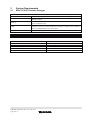
System Requirements
2.1
M32C PC4701 Emulator Debugger
Target host PC
PC
OS
Memory
HDD
Display Resolution
Emulator
PC4701U
IBM PC/AT compatible with Pentium III 600MHz or higher
Windows XP
Windows 2000
128MB or more (and in addition, ten or more times as much size as
the load module file).
Hard disk available capacity for installation: 100MB or more.
Prepare an area at least double the memory capacity (four-times or
more recommended) as the swap area.
1024 x 768 or higher recommended
PC4701M
PC4701HS
Emulation Pod for M32C/80 Series
M30830T-RPD-E
MCU file
M30835.MCU
Emulation Pod for M16C/80 Series
M30803T-RPD-E
M30800T-RPD-E
MCU file
M30803.MCU
M30800.MCU
REJ10J1589-0100 Rev.1.00 Jul.01.07
page 6 of 8
PC4700H
3
Version Report
This section describes the specification of the changed software.
3.1
M32C PC4701 Emulator Debugger V.1.03.00
In this version, the following specifications were changed from the previous version M32C PC4701
Emulator Debugger V.1.02.00.
This version supports all of the function extensions and the revisions to the restrictions in the
High-performance Embedded Workshop V.4.02.00 and V.4.03.00. For more details, please refer to the
RENESAS TOOL NEWS “061216/tn2” issued on December 16, 2006 and “070701/tn1” issued on
September 1st, 2007.
3.1.1
Revisions to Restrictions
1. A limitation has been corrected: The registers can not be referenced correctly in the IO window.
(For more details, refer to the RENESAS TOOL NEWS “061216/tn7” issued on December 16,
2006)
2. A limitation has been corrected: if the On Demand check box is checked in the Debugging
Information tab of the Init dialog box, which appears when you invoke your debugger, target
programs may not be loaded successfully on MCUs and not run properly. (For more details,
refer to the RENESAS TOOL NEWS “070416/tn8” issued on April 16, 2007).
3. A limitation has been corrected: If the size of the variable to be referred by the quick watch
feature is larger than 256 bytes, High-performance Embedded Workshop would crash. (For
more details, refer to the RENESAS TOOL NEWS “070601/tn5” issued on June 1st, 2007).
3.1.2
Functional Extensions and Modifications
1. Displaying source files information automatically in the Workspace Window.
When a download module file is downloaded, the High-performance Embedded Workshop
obtains source files information contained in the download module file through its debug
information, and displays it under "download module" node in the Projects tab on the
Workspace Window. Note that this function is available only for debugging the debug-only
projects.
2. Supports C watch window included in High-performance Embedded Workshop V.4.03. The
feature Changing scope of the variable and suppression leading zero are supported.
3. The option to specify the size (1byte or 2byte) of enumerator type is added.
4. Supports “Disconnect target” feature.
5. When the instruction is modified by the line assemble feature, if the old instruction length is
longer than the new instruction length, NOP instructions are inserted automatically so as to
suit the old instruction length.
6. The instruction format specifier is displayed for each instruction in disassembly. And also, can
be switched not to display.
7. Supports to substitute the bit field member variable.
8. The default value of “Reset CPU after download module” is changed to be checked.
9. The option not to access memory while CPU is wait/stop mode is added.
3.2
M32C PC4701 Emulator Debugger V.1.02.00
In this version, the following specifications were changed from the previous version M32C PC4701
Emulator Debugger V.1.00.00.
This version supports all of the function extensions and the revisions to the restrictions in the
High-performance Embedded Workshop V.4.01.00 and V.4.01.01. For more details, please refer to
RENESAS TOOL NEWS “060701/tn1” issued on July 1, 2006 and “060801/tn1” issued on August 1,
2006.
3.2.1
1.
Revisions to Restrictions
A limitation has been corrected: The structure member variables, union member variables, or
class member variables whose name begins with a letter of ‘e’ or ‘E’ immediately followed by a
numeral, are not referenced.
REJ10J1589-0100 Rev.1.00 Jul.01.07
page 7 of 8
For more details, refer to the RENESAS TOOL NEWS RSO-M3T-PD32RM-060116D issued on
January 16, 2006.
2. A limitation has been corrected: If the Task Pause button is pressed while a service call is
being serviced, the target task of the service call does not enter the pause state but goes to the
object-waiting state though it is displayed in the debugger screen that the task has entered
the pause state.
For more details, refer to the RENESAS TOOL NEWS RSO-M3T-MR308-060416D issued on
April 16, 2006.
3.2.2
3.
Functional Extensions and Modifications
These commands, which can be invoked in Command Line, have been supported:
breakpoint, breakpoint_disable, breakpoint_display, breakpoint_clear
register_display, register_set
disassemble, assemble
REJ10J1589-0100 Rev.1.00 Jul.01.07
page 8 of 8