1
Cleveland Range
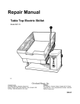
REPAIR MANUAL
Model No.
42CKEM24/36/48
42CKGM200/250/300
42CKDM
42CKSM
Cleveland Range, Inc.
UNITED STATES
CANADA
1333 East 179th St
Cleveland. Ohio 44110
Phone:(216 )481-4900 • FAX: (216) 481-3782
Garland Commercial Ranges • 1777 Kamato Rd.
Mississauga, Ontario CN L4W 1X4
Phone: (416) 624-0260 • FAX: (416) 624-0623
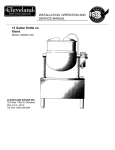
Installation, Use and Care Instructions
Convection Steamer
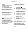
INSTALLATION
INSTALLATION SAFETY
WARNING
Installation of this equipment must be
accomplished by qualified installation personnel,
working to all applicable local and national codes.
Improper installation at this product could cause
injury or damage.
D0 NOT store or use gasoline or other flammable
vapors and liquids in the vicinity of this or any other
appliance.
The flooring that will be directly under the boiler
must also be made of a noncombustible material.
Cleveland Range equipment is designed and built to
comply with applicable standards for manufacturers.
Included among those certification agencies which have
approved the safety of the equipment design construction
are: UL, A.G.A., NSF, ASME, CSA, CGA, and others.
WARNING
INJURY TO PERSONNEL AND EQUIPMENT DAMAGE
may result from an improper dram connection.
4. The dram line outlet discharges exhaust steam and hot
condensate. Connect 1-1/2-inch. IPS piping (or larger) 10
extend the dram line to a nearby open floor dram. Up to
two elbows and six feet of 1-1/2-inch IPS (or larger)
extension pipe should be connected to the drain
termination. Drain piping extended six to twelve feet or
using three elbows, should be increased to 2 -inch IPS No
more than two pieces of Cleveland Range equipment
should be connected to one common drain line. The
maximum length of extension from the dram
termination should not exceed six feet and use no
more than two elbows. The extension piping must
have a gravity flow and vent freely to the air. This
drain outlet must be free-vented to avoid the
creation of back pressure a the steamer cooking
compartments. To ensure a vented drain line, DO
NOT, UNDER ANY CIRCUMSTANCES, CONNECT
THE DRAIN OUTLET DIRECTLY TO THE FLOOR
DRAIN OR SEWER LINE. Do not run the drain line
discharge into PVC drain piping or any other drain
piping material not capable of sustaining 180 F
operation.
Cleveland Range equipment is designed and certified for
safe operation only when permanently installed in
accordance with local and/or national codes. Many local
codes exist and it is this responsibility of the owner and
installer to comply with these codes.
NOTE Direct steam connected pressure steamers do not
In no event shall Cleveland Range assume any liability
for consequential damage or injury resulting from
installations which are not in strict compliance with our
installation instructions Specifically, Cleveland Range will
not assume any liability for damage or injury resulting
from improper installation of equipment including, but not
limited to, temporary or mobile installations.
5. Connect COLD water supply plumbing to the line strainer.
INSTALLATION INSTRUCTIONS
1.These instructions must b e retained by the owner/user
for future reference. Gas-fired boilers are only to be
installed in noncombustible areas that have provisions
for adequate air supply. The term "boiler'' will be used
synonymously with "steam generator"
2. Position: For proper operation and drainage, the
equipment must be level It should be placed next to
an open floor drain. DO NOT POSITION THE UNIT
DIRECTLY ABOVE THE FLOOR DRAIN. Observe all
clearance requirements to provide air supply for
proper operation. as well as sufficient clearance for
servicing. The surrounding area must be be free and
clear of combustibles. Dimensions and clearance
specifications are shown on the specification sheet.
3. Install in accordance with local codes and/or the
National Electric Code ANSI/NFPA No. 70-1987.
Installation in Canada must be in accordance with the
Canadian Electrical Code CSA Standard C22.1
Equipment that is connected to electricity must be
grounded by the installer. A wiring diagram is provided
inside the base cabinet.
require a cold water connection, and therefore steps 5 and
6 do not apply. Refer directly to step 7. A kettle fin
faucet, if so equipped, requires a hot and/or cold water
connection. The data contained in step 5 for cold
water also applies to hot water.
(Never connect hot water 10 the boiler-water fill line
strainer.) Constant flow pressure must he maintained
between 35 and 60 psi, and not experience a
pressure drop below 35 psi when other appliances
are used. If the water pressure exceeds 60 psi, a
pressure reducing valve must be installed in the
water supply plumbing 10 reduce the water
pressure 10 less than 60 psi. Locations and
pressure data are shown on the specification sheet,
1/4-inch IPS plumbing is sufficient for water supply
lines up to 20 feet in length, but water supply lines
longer than 20 feet should be at least 3/8-inch IPS.
Flush water supply lines thoroughly before
connecting them 10 the unit Use water which is low in
anal dissolved solids content and low in gas content to
prevent internal scaling, pitting and corrosion of the
steam generator, and carry-over of minerals into the
steam. Water which is fit to drink, can still contain highly
detrimental impurities.
NOTE: If equipped with a kettle and kettle water fin swing
spout, 3/8-inch (10mm) not and/or cold water
connections) win be required at the swing spout
valve.
6. Turn on the cold water supply to the unit. Ensure that the
manual water valve, inside this base cabinet, is open.
Installation, Use and Care Instructions
Convection Steamer
For Steam Con Steam Generators: Connect Steam supply
piping to the input side of the steam coil. Location and
pressure data are shown on the specifacations sheet
Incoming steam pressure must be regulated between 35
and 45 psi A 3/4-inch strainer, equipped with a 20 mesh
stainless steel screen must be supplied and installed at the
incoming steam connection point. Flush the steam line
thoroughly before connecting it 10 the boiler. To ensure an
adequate volume of steam, the branch steam supply line
must be 3/4 -inch IPS minimum. Connect the inverted
bucket trap to the outlet end of the steam coil. Fill the
trap with water before installing it. A permanent 115 volt
electrical connection is required at the junction box. The
junction box location is shown on the specification sheet.
The unit must he electrically grounded by the installer.
For Direct-Steam Connected Steamers/Kettles: Connect
steam supply piping to the input side of the line strainer.
Location and pressure data are shown on the
specifacation sheet. Flush the stream line thoroughly
before connecting it to the steamer. To ensure adequate
of steam the branch steam supply line must be 3/4 -inch
IPS minimum (Direct-steam -connected kettles require 1/2inch require IPS pipe if the kettle total capacity is 20
gallons or less, and 3/14-inch IPS pipe if the total capacity
exceeds 20 gallons.) A permanent 115 electrical
connection is required at the junction box. The junction
box location is shown OB the specification sheet. The
unit must be electronically grounded by the installer.
7. Connect the primary fuel supply in accordance with the
following instructions Location and other data are shown
on the specifications sheet.
For Gas-Fired Steam Generators: Post in a prominent
location, instructions to be followed in the event the user
smells gas. This information shall be obtained by
consulting the local gas supplier. Install a sediment trap
(drip leg) in the gas supply line then connect gas supply
piping to the boiler gas valve piping. GAS-FIRED
EQUIPMENT IS DESIGNED FOR INSTALLATION
ONLY IN NON-COMBUSTIBLE LOCATIONS. THIS
INCLUDES THE FLOORING THAT WILL BE
DIRECTLY UNDER THE EQUIPMENT. Location,
plumbing size, and pressure dataare shown on the
specifacation sheet. Boilers rated less that 225,000 BTU
require 3/4-inch IPS gas supply piping, and boilers rated
at 225,000 BTU or more require 1-inch IPS gas supply
piping. Natural gas pressure must be between 4''-14"
water column, and L.P. gas supply pressure must be
between I2'' - 14'' water column. NEVER EXCEED 14''
WATER COLUMN (1/2 psi) GAS PRESSURE. If the gas
supply pressure exceeds 14'' water column, a pressure
regulating valve most toe installed in the gas supply
plumbing to reduce the gas pressure 10 less than14''
water column. Installation must be in accordance with
local codes, or in the abcense of local codes, with the
National Fuel Gas Code, ANSI 2223.1 1984. Insallation
in Canada mast be in accordance with Installation codes
for Gas Burning Appliances and Equipment B149.1 and
B149.2 Use a gas pipe joint compound which is resident
to LP gas. Turn the gas valve control knob to ON (the
word "OB" on the knob will be opposite the index on the
valve's body). Test an pipe joints for leaks with soap and
water solution. Never obstruct the flow of combustion
and ventilation air. Observe an clearance requirements
to provide adequate air openings into the combustion
chamber The appliance and its individual shut-off valve
must be disconnected from the gas supply piping
system during any pressure testing of that system at
test pressures in excess of 14" water column (1/2 psi or
3.45 kPa). The appliance must be isolated from the gas
supply piping system at test pressures equal to or less
than 14'' water column (1/2 psi or 3.45 kPa). A
permanent 115 volt electrical connection is required at
the junction box. The junction box location is shown OB
the specification sheet. The unit must be electricity
grounded by the installer.
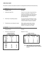
Installation Checks
Proper operation of the Cleveland Convection Steamer is
dependent upon proper installation. Alter the steamer has
been installed. A few quick checks could save unnecessary
service calls.
1. The unit must be level
2. The Convection Steamer requires a cold water connection
for proper, efficient operation. DO NOT USE HOT WATER
The cold water must be connected to the line strainer
located at the front lower-right of the steamer base
3. Check that the manual water supply valve is open
4. Check an water supply lines and valves for leaks
5. Check that the water supply pressure and water quality
meet the requirements of installation paragraph 5
6 On electric units, verify that the supply voltage meets the
voltage requirements on the rating plate 'inside the base
cabinet, and the •voltage shown on the packing slip Verify
that the unit is protected with a seperate fused disconnect.
and is properly grounded in accordance with the National
Electric Code
For Electronic Powered Steam Generators: Connect
electric power: location and data are shown on the
specifications sheet Provide connection as required by
the unit; either directly to the single contactor, or to the
terminal block (when equipped with multiple contactors).
Electric supply must match power requirements
specified on the data plate inside the base cabinet. The
copper wiring most be adequate to cany the required
current at the rated voltage. A separate fused
disconnect switch must be supplied and installed. The
unit must be electrically grounded by the installer.
7. On gas, steam con, and diret-steam -connected units, verify
that there is a 115 Volt connection at the handi-box located
on the left side of the base at the bottom front.
2
Installation, Use and Care Instructions
Convection Steamer
OPERATION
8. On steam coil units , me incoming steam pressure
must be 35 10 50 psi Less than 35 pa will not
effectively operatethe unit. Pressure in excess of 50
psi must be reduced (with a a pressure reducing
valve) to 35 to 50 psi.
Operation of the Cleveland Range Convection Steamer is
very easy. Each operator should read and understand the
following procedures to effectively start, operate, and shut
down the steamer each day. The owner(s) and operator(s)
of this equipment should be aware that live steam can
cause serious injuries, and pay particular attention 10 the
WARN INGS in this text. These instructions are 10 be
retained by the owners) and operator(s)) for future
reference.
WARNING
INJURY TO PERSONNEL AND EQUIPMENT DAMAGE
may result from an improper drain connection.
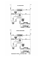
Controls and Control Panels
9. Check that the drain lines meet the installation
requirements specified in installation paragraph 4.
There are two steam generator control arrangements and
two steamer compartment control panels available for
Cleveland Range Convection Steamers. The steam
generator controls are illustrated The steamer compartment
control panels are illustrated i n Figures 2 and 3. Compare
these figures with the equipment supplied, and identify
which control and panel combinations apply.
10. After completing checks 1 through 9, and correcting
any deficiencies, refer to the Start-Up and Preheat and
Preheat instructions in the Operation section. Verify
that the unit operates
properly, and make checks 11 and 12. and 12
11. Check ensure that the water the boiler sight gage
glass automatically says about 1/3 fan when the boiler
is started
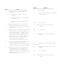
Steam Generator Controls
The steam generator controls are located on the front face
of the steamer base unit. The switches are 10 the left of the
pressure gage, as illustrated in Figure 1. Most Cleveland
Range<Convection Steamers have steam generator built
into the base unit which supplies steam to the cooking
compartments. However, an external steam supply may
also be used. Units with a built-in boiler have both the
POWER rocker switch and the STEAM momentary
switch next 10 the pressure gage. Units with an external
steam supply have the POWER rocker switch only.
They do not have the STEAM momentary switch.
12. Check to ensure that the stream pressure gage
registers 110 psi pa.
The steam pressure is factory-adjusted to provide the
proper pressure. In some cases , however,, the factory
set- may shift down 10 shaking and resetting win be
required after installation. Proper adjustments and
maintenance procedures are detailed on a separate
data sheet entitled "Steam Pressure Adjustments ."
Adjustments be made only by qualified service
personnel The factory pressure settings shown in the
accompanying
chart should never be exceeded
Steamer Compartment Control Panels
Figure 2 illustrates the standard electronic controls: the Key
Pad Control Panel This panel has a rocker switch, a key
pad, and a digital timer. Figure 3 illustrates the optional
electromechanical controls: the Dial Timer Control Panel.
This panel] has a rocker switch and dial timer Steamer
functions are the same for both the standard and optional
panel configurations. Operating details are slightly different
especially when setting the automatic operating time. For
clarity, two sets of instructions are provided for cooking
operations.
Gage Pressure Reading with No Steam
Flow* (Static Pressure)
Self-Contained Steam Generator Steam , Gas or
Electric
Operating Pressure Switch
10 psi
High Limit Safety Pressure Switch
15psi
Setf-Contained Steam Coil Generator
Operating Pressure Switch 10 psi High Limit
Safety Pressure Switch
15 psi Steam
Supply Pressure Range
3545 psi
Direct-Connect (to House Steam Supply)
Steamer Pressure Reducing Valve 10 psi Steam
Supply Pressure Range
15-45 psi
•with or without kettle
3
Range
Installation, Use and Care Instructions
Convection Steamer
2. Start the steam supply. The steam supply is either an
integral steam generator (boiler) built into the base unit. or
external steam supply.
• For units without a built-in boiler, refer to the startup
procedures tor the external steam supply and be sure it
is running properly. As soon as the pressure gage on
the Convection Steamer registers 10 psi. steamer
preheating may begin. Skip the remainder of step 2 and
begin step 3.
• For units with a built-in boiler. fin the boiler with water
and start the steam generator as described i n steps a.
through d. below
a - Press the ON end of the POWER on-off rocker switch
located next 10 the steam pressure gage (Figure 1). The
red indicator light in the POWER rocker switch turns on
and the steam generator begins to fill with water. This
takes about 5 minutes
b. When the-water level in the steam generator reaches a
safe operating level, the amber light in the STEAM
momentary switch turns on. Whenever the amber light is
on, the heaters, steam supply or burners arc off. and no
steam is being generated. The energy source (electric,
gas. etc..) cannot be activated until the boiler
contains sufficient water indicated by The amber light
c. Press the STEAM momentary switch to produce steam in
the boiler. This activates the energy source (electric
heaters, gas burners or steam solenoid valve) and
the amber light turns off.
The STEAM switch must be pressed to re-start the
steamer after it is shut off for any reason (including a
brief power interuption). No attempt should be made to
operate the equipment during a power failure.
NOTE: For steamers with built-in gas-fired boiler:
If the burners fail 10 ignite m four seconds, a safety
circuit de- energizes the system. In this event, toggle
the POWER rocker switch to the OFF position and
back to the ON position. The amber light in the
STEAM momentary switch lights. Wait five minutes,
then press the STEAM momentary switch to start the
burner ignition cycle once again.
Start-up and Preheat
WARNING
Do not attempt to start or operate the Convection Steamer
during a power failure are not energized, and serious injury
to personnel or damage to equipment may result.
1. Inspect the steamer. Check: the cooking compartments 10
ensure that the steam tubes and drain screens are in
place and secure. Check inside the steamer base cabinet
10 ensure that the manual drain valve is closed and the
manual water supply valve is open.
d.
About20 minutes after starting the boiler in step c, the
e.
steam pressure guage on the unit base should
register 10 psi.
3. Preheat the Convection Steamer cooking compartments.
For accurate, efficient cooking times, the cooking com partments should be preheated during startup.
NOTE: With a steamer/kettle combination, if both must
be used at the same time, always heat the kettle first,
When kettle contents begins to simmer, and steam
pressure returns, the steamer compartments may be
preheated.
a-
Close the compartment door by gently swinging it
shut.
b. Refer to timer setting instructions under Automatic
Operation for the appropriate control panel Set the
Installation, Use and Care Instructions
Convection Steamer
timer for each compartment to one minute, and start
the
cooking cycles Steaming begins in each compartment.
NOTE: On Convection Steamers equipped with
electronic key pad controls panels, the timer
does not begins counting down unti l the cooking
compartment reaches operating temperature.
This may take 2 or
3 minutes if the steamer has not been operting.
c. Steaming continues for the set one minute When
the preheating completed, the steam automatically
shuts off and a 3 -second alarm sounds. The
Convection Steamer is ready for cookmg
operations.
COOKING OPERATIONS
The control panels mounted on the cooking
compartments regulate cooking operations. Although
cooking operations are similar for all Convection
Steamers, regardless of control panel configuration,
separate instructions are provided for each control panel
type.
Cooking Operations for
The Key Pad Control
Panel
The electronic key pad control panel is illustrated in
Figure 2.
The Cleveland Range Convection Steamer has two
cooking modes: Manual and Automatic. The Manual
Mode provides continuous steaming and is turned on and
off by the MANUAL/TIMED rocker switch. The Automatic
Mode monitors cooking time and temperature to provide
accurate, efficient, uniform steam cooking.
NOTE: Whether using timed or manual cooking mode,
optimum steam heat transfer, and therefore a
higher quality food product, is achieved when
shallow, perforated, uncovered pans are used.
WARNING
LIVE STEAM may cause severe
burns. Use extreme caution when opening the steamer
door. Turn face away from the steamer when first
opening the door. Do not look into the cooking
compartment until steam has cleared. KEEP HANDS
OUT OF THE COOKING COMPARTMENT TO
PREVENT BURNS.
Manual Cooking Operation - Key Pad Controls
Use manual mode for a continuous supply of steam for
long periods, or if the required cooking time is unknown
and frequent inspection isrequired.
1. Place the pan(s) of food into the cooking
compartment.
2. To START the flow of steam, press the MANUAL end
of the MANUAL/TIMED rocker switch, located below
the timer. Steam immediately starts flowing into the
cooking compartment.
3. If food inspection is required during steaming, refer to
the LIVE STEAM WARNING above. Use extreme caution
when opening the steamer door during steaming
operations.
4. Although the timer cannot turn the steam off in manual
mode it can be used as a conventional cooking timer.
Refer to the timer setting instructions under Automatic
Operation and set the timer. The timer will count down
the set period and sound the buzzer, but IT WILL NOT
TURN OFF THE STEAM-AFTER THE ALARM
SOUNDS.
5. To STOP the flow of steam, press the Timed end of the
MANUAL/TIMED rocker switch. Steam stops flowing into
the cooking compartment.
Automatic Cooking Operation - Key Pad Controls
Each Convection Steamer cooking compartment is
equipped with an independent electronic digital timer, which
has a maximum s etting of 99 minutes and 99 seconds.
Each timer is connected to a temperature sensing device in
the cooking compartment. THE SENSOR CIRCUIT
ALLOWS THE TIMER TO COUNTDOWN ONLY WHEN
THE COOKING COMPARTMENT IS AT THE PROPER
COOKING TEMPERATURE. This assures uniformity in the
cookmg times as the timer automatically compensates for
food product defrosting and/or heat-up time.
1. Place the pan(s) of food into the cooking compartment
2.Clear and reset the timer. The timer can be set only when
the COOKING TIME display is clear. Press the CLEAR
key on the number pad to zero the timer.
3. Set the Desired Cooking Time. The cooking time display
contains four digits. The left two digits are minutes, and
the right two digits are seconds. The display 12:34 is set
for 12 minutes and 34 seconds.
a. To set the cooking time: change the required cooking
time to minutes and seconds, press the number keys for
the minutes and then press the number keys for the
seconds, If the cooking time 99 seconds or less, only
press the number keys for seconds.
b. Example 1. To set the timer for 1 hour and 15 minutes:
Change 1 hour (60min) and 15 minutes to 75 minutes.
Press the following number keys in sequence: 7500.
The display will read 75:00 when property set for 1
hour and 15 minutes.
c. Example 2. To clear the time numbers set in example
1. press the CLEAR key on the number pad. The
display returns to 00:00.
d. Example 3. To set the timer for 1-5 minutes: Change
the time to 1 minute and 30 seconds. Press the
following number keys in sequence: 1,3,0. The
display will read 01:30, when set for 1.5 minutes. AIl
seconds method: Change the 1.5 minutes to 90
seconds and press 9 0. The display will read 00:90,
when set for 1.5 minutes.
Installation, Use and Care Instructions
Convection Steamer
4. Press the START/STOP key to start the timer. When the
START/STOP key is pressed, steam enters the cooking
compartment.
a. THE TIMER WILL BEGIN TO COUNT DOWN ONLY
AFTER THE COOKING COMPARTMENT
REACHES PROPER COOKING TEMPERATURE.
The timer automatically delays to compensate for
defrosting and/or food product heat-up time.
b. For example, a timer setting of 10 minutes may in
fact take 11 or 12 minutes for the timer to count
down and the alarm to sound. This is normal.
Heating the compartment and food to cooking
temperature uses the additional time.
c. To stop or reset the timer, press and hold the
START/STOP key. The cooking one display returns
to the last time setting.
• To restart the same time, press the
START/STOP key.
• To set a new time press the CLEAR key, and set
the new time.
5. When the timer counts down to zero, an alarm sounds
continuously. Press the START/STOP key to silence
the alarm. The cooking time display returns to the last
time setting. Either run this same setting again or clear
and reset the timer.
6. Example 4. To cook two 14 minutes cycles: Press the
CLEAR key to clear the timer. Press the following
number keys in sequence: 1,4,0,0. The display shows
14:00. Press the START/STOP key to start the timer.
When the display counts down to zero, the alarm
sounds. Press the START/STOP key, and the display
returns to 14:00. Press the START/STOP key to start
the second 14 minute cycle.
Manual Cooking Operation - Dial Timer Controls
Cooking Operations for
2. Place the pan(s) of food into the cooking compartment.
The Dial Timer Control
Panel
3. Set the Desired Cooking Time. Turn the dail until it points
to the desired cooking time. When the dial timer is set.
steam enters the cooking compartment.
The dial timer control panel is illustrated in Figure 3.
4. When the timer counts down to zero, as alarm sounds for 4
seconds, and steam flow into the cooking compartment
stops.
Use Manual mode for a continuous supply of steam for
periods longer than the timer limits (99 minutes), or if the
required cooking time is unknown and frequent inspection is
required.
1. Place the pan(s) of food into the cooking compartment.
2. To START the flow of steam, press the MANUAL end of
the MANUAL/TIMED rocker switch, located below the
timer.
3. If food inspection is required during steaming, refer to the
LIVE STEAM WARNING above. Use extreme caution
when opening the steamer door during steaming
operations.
4. Although the timer cannot turn the steam off in manual
mode it can be used as a conventional cooking timer.
Refer to the timer setting instructions under Automatic
Operation and set the timer. The timer will count down the
set period and sound the buzzer, but IT WILL NOT TURN
OFF THE STEAM AFTER THE ALARM SOUNDS.
5. To STOP the flow of steam, press the Timed end of the
MANUAL/TIMED rocker switch.
Automatic Cooking Operation
Dial Timer Controls
Each Convection Steamer cooking compartment is equipped
with an independent dial timer. This timer controls the
cooking compartment steaming cycle. Use automatic mode
when an exact cooking time is required. Steam cooking
begins when the timer is set, and automatically stops when
the timer counts
down the set period.
1. Check that the MANUAL/TIMED rocker switch is in the
TIMED position. If it is not. press the TIMED end of the
MANUAL/TIMED rocker switch.
The Cleveland Convection Steamer has two cooking
modes:
Manual and Automatic. The Manual Mode provides
continuous steaming and is turned on and off by the
MANUAL/TIMED rocker switch. The Automatic Mode
monitors cooking time to provide accurate, efficient, steam
cooking.
NOTE: Whether using timed or manual cooking modes,
optimum steam heat transfer, and therefore a higher
quality food product, is achieved when shallow,
perforated, uncovered pans are used.
Boiler Shutdown
The red-lighted power switch must be shut off for 3 minutes
a minimum of once every 8 hours to automatically drain
highly mineralized water from the boiler, which reduces the
formation of scale. See Step 1 in CARE AND CLEANING
instructions, which follow.
WARNING:
LIVE STEAM may cause severe bums. Use extreme caution
when opening the steamer door. Turn face away from the
steamer when first opening the door. Do not look into the
cooking compartment until steam has cleared. KEEP HANDS
OUT OF THE COOKING COMPARTMENT TO PREVENT
BURNS.
6
Installation, Use and Care Instructions
Convection Steamer
opening. If it does not, the drain must be cleaned before
using the steamer.
4. Once a week, remove the steam robes and clean the
orifices. First, remove the pan slides by lifting upward
and toward the center of the compartment. Pressing
backward on the steam tube will allow its front eyelet to
clear the compartment stud. The tube is then angled
toward the center of the compartment just enough to
clear the stud and be pulled forward, out of its socket.
The orifices can be cleaned easily with a paper cap.
Then. thoroughly wash and rinse all s team tubes. This
can be done m a dishwasher. Lubricate each tube's
tapered end with cooking oil before replacing in the
steamers compartments. Be sure all four steam tubes
are securely in place before activating the compartment.
The tubes are interchangeable and may be placed m
any spot m either compartment.
5. To prolong door gasket always leave compartment door
ajar when not in use.
6. Exterior Care: Allow steamer to cool before washing. Use
the same cleaners and cleaning procedures as for other
kitchen surfaces of stainless steel and aluminum. Mild
soapy water, with a clear water rinse, is recommended.
Do not allow water to run into electrical controls. Always
turn off equipment power before using water to wash
equipment. Do not hose down the steamer.
CARE AND CLEANING
The Cleveland Convection Steamer must be cleaned
regularly to maintain its fast, efficient cooking
performance, and to ensure its continued safe, reliable
operation.
1. The boiler must be drained (Blowdown) after a
maximum of 8 hours of use. If the boiler feedwater
contains more than 60 pans per million of total
dissolved solids, the boiler must have a blowdown more
often, the frequency depending upon the mineral
content of the feedwater. Blowdown means the boiler
must be drained under pres -sure.
THE BOILER BLOWDOWN IS PERFORMED BY
SIMPLY SHUTTING OFF THE STEAMER'S REDLIGHTED POWER SWITCH WHILE THE BOILER IS
AT NORMAL 10 PSI OPERATING PRESSURE. WHEN
THE BOTTOM OF THE POWER ROCKER SWITCH IS
PRESSED, ITS RED LIGHT GOES OUT, AND THE
DRAIN VALVE AUTOMATICALLY OPENS, DRAINING
THE BOILER. AN AUTOMATICALLY-TIMED DRAIN
WATER CONDENSER WILL FLUSH THE DRAIN FOR 3
MINUTES, THEN SHUT OFF. AFTER 3 MINUTES THE
STEAMER IS READY TO BE RESTARTED.
When steam is produced, the water in the boiler is being
the boiler with the water, remain in the boiler as the
water boils away as steam. When allowed to
accumulate, the
water becomes highly mineralized, which results in erratic
operation, lime build-up corrosion, and premature
electric heater failures. In some cases, complete boiler
replacement becomes necessary, which is extremely
ex-pensive. By draining the boiler under pressure, most
sedi-meat present will be flushed down the drain.
2. The steamer is equipped with a drain in the back of the
cooking compartment. No compartment should be
operated without the drain screen in place. This screen
prevents large food particles from entering and possibly
plugging the drain line. Any restriction of the drain line
may cause a slight build-up of back-up pressure in the
compartment, resulting in steam leaks around the door
gasket. It also may adversely affect the convection
action of the steam in the compartment, which is critical
to optimum performance. Pouring U SDA approved
drain cleaner through the compartment drains once a
week will help to ensure an open drain. A manual
(hand crank) drain auger, or "snake'', may be safely
used to clear obstructions in the compartment drains.
Do not use a power auger, as damage to the plastic
drain system will result.
With the steamer off open the cooking compartment
doors and allow the steamer to cool before cleaning the
cooking compartments and their compartments.
3. At the end of each day's operation, wash the pan
slide's, s team tubes, door gaskets, and compartment
interiors with mild detergent and warm water, either by
hand or in a dishwasher. Rinse thoroughly with clear
water. Rinse water should drain freely through the
compartment drain
Printed 6/90
WARNING
Do not store or use gasoline or other flammable vapors
and liquids in the vicinity extras or any other appliance.
MAINTENANCE
Periodically, a qualified serviceman should be
summoned for routine preventive maintenance.
1. The blowdown procedure will not completely remove the
mineral deposits that adhere to the top of the boiler. A
chemical descaling should be done by a boiler treatment
specialist. This should be done once a year in average
water conditions, but in poor water areas it may be
needed two or three times a year.
2. Periodic boiler inspection should be made by a qualified
serviceman.
3- Once every three months, the cold water line strainer
should be cleaned.
Cleveland Ranges supports a comprehensive network of
Maintenance and Repair Centers (regional pans and
service distributors) throughout the United States and
Canada. Please contact your nearest distributor for the
name of an authorized service agency in your area, or for
replacement pans and information regarding the proper
maintenance and repair of Cleveland Range equipment. In
order to maintain the various agency safety certifications,
only factory-supplied replacement parts should be used.
The use of other than factory-supplied replacement parts
will void the warranty.
7
Cleveland Range. Inc.
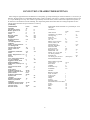
CONVECTION STEAMER TIMER SETTINGS
Timer settings are approximate due to the differences in food quality, age. shape and the degree of doneness desired 1: is no necessary to
add water- Perforated pans are recommended. Starred items (*) must be cooked in solid pans or- containers. Items marked with two stars
(**) require handling in two steps. First. steam for approximately 1/2 the time shown, remove from steamer separate thawed portion, or
stir and return to the steamer for the time remaining. The compensating feature of the timer allows the cooking compartment to reach
cooking temperature before the preset time starts to count up.
(In Minutes)
SEAFOODS: Steam all seafoods on a perforated par- with
VEGETABLES:
Fresh
Frozen
catch pan.
Artichoke
12
Asparagus, spears
4
6
(In Minutes)
Beans, green 2" cut
6
5
Fresh
Frozen
French cut
4
5"
Clams in shell
3-5
whole
6
4
Cod fillets. 5 oz- portions
3
4
Broccoli, spears
3
2-3
Crab legs. king
4-6
flowerettes
2-3
2-3
Snow crab
2-4
chopped
6-8
Crab. live, 4 oz
4
Brussels sprouts
4-5
4
3/4 - 1 Ib.
12
Cabbage
Halibut. 6-8 oz portions
4-6
6-8
12-16 wedges/head
4
Lobster, whole, 1 Ib.
7-9
Cabbage.
Lobster tails. 8 oz
8-10
whole - to remove leaves
2
defrosted. butterflied
4-6
for cabbage rolls
Mussels in shell
2
Carrots. baby whole
10
6
Oysters in shell
2-4
sliced. crinkle cut
7-8
3
Red snapper. 8 oz4-5
4-5
diced
2
Salmon steak. 8 oz.
6
7
Cauliflower, flowerettes
4-5
3-4
whole
10
Shrimp, 10 ct. per Ib. lQF
3
4-6
5 Ib. block, peeled &"
Celery. diagnonal cut 1 1/2 3
deveined 30 ct.
6-8diced
2
1
minced
1
5 Ib. block, green, 26-30 ct
(nested pan)
10Corn, yellow whole kernel
2
EGGS
(Medium
Sized):
on cob. cobbettes
6
12"
Eggptant. sliced, diced
1
Hard cooked for egg salad.
Mixed vegetables •
3-4
potatoe salad
10-12
Mushrooms, whole (1 1/2" 3
Soft cooked
•a
sliced
1
Coddled
6
Onions, diced, sliced
2-3
1
Poached in a cup
2-3
whole
4
2
Scrambled*
6-7Peas. green
2
FRUITS:
Potatoes. whote 8 oz
30-35
peeled. quartered. fresh
12-19
Blanch tor peeling
peeled. diced
8-10
Fresh: Avocado
1
Potatoes, sweet whole
30-35
Apple. cored
1
Spinach leaf
2
21Grapefruit
1
chopped
21Orange
1
Squash, acorn halves
15
Apricot
1
butternut. quartered
7
Pineapple, whole
2
whipped*
20Dried': add water to re-hvdrate
spaghetti squash, halves
15-18
Apple
10
Tomatoes, whole, sliced
1
Apricot
10
Turnips, whole
20-25
Peach
10
Zucchini. sliced
2-4
2-4
Pear
10
Prune
10
9
(continued)
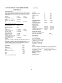
CONVECTION STEAMER TIMER
SETTINGS
MEATS & POULTRY:
Steam meats and poultry in nested pans. as juices can be used for
gravy, sauces. beef stock and soups. The size of portion, thickness
of cut, grade, should be considered when selecting a timer setting
for doneness.
POULTRY
Fresh
Frozen
Turkey, whole
6-8 min/lb.
Chicken, 5-8 oz breaded
pieces
18-20 min.
halves. 1 1/4 -1 1/2 .lb. per
half
20-24 min.
PORK, SAUSAGE, HOT DOGS:
Pork- Chop. 4 count/lb.
Italian sausage. 4 oz. portion
Ribs. 3 lb and down
Hot dogs 8 count/lb.
BEEF:
Cubes, 1 1/2"
Ground chuck for chili
Pot roast, choice
Rump roast. choice
boned- rolled, tied
Meat loaf. 4 ib. loaf
Liver baby bee?. 8 oz- slice
Corned beef. 6-8 Ib. CUT
add 1/2" water to pan
STEAKS:
6-8 min/lb.
20-24min.
12 min/lb.
5 min/lb.
2-4 min.
5
7
5
8
8
10
min.
min.
min.
min
min.
Min.
PREPARED ENTREES:
Fresh
Frozen
25 min
20 min.
20-25 min.
20-25 min.
20-25 min
6-8 min.
25-30 min.
25-30 min.
25-30 mm.
12 min.
Full size pans
Cabbage rolls stuffed
cover' with tomato
sauce & serve
Casserole dishes"
beef stew,
stroganoff
Lasagna". freshly prepared
reheat each serving 4"
10min.
10 mm.
20-26 min
2min
6-7 min./lb.
4-6 min/lb.
8-12 min/lb.
STEAKS:
Strip steak — 10 oz12 oz
T-bone — 12 oz
16oz
18 oz22 oz'
6 min/lb.
4-6 min/lb.
DEHYDRATED FOODS:
Potatoes': 2 1-2 # random sliced
plus 5 cups cold water/lb.
2-4 min.
RICE & BEANS:
12 min.
17
min.
Rice*. long again
4 cups cold water/lb.
Beans*, pre-soaked over-night
1 lb. beans + 1 1/4 qts. water
Beans*, unseated.
l to. beans +1 1/2 qts water
Refried beans'. 2 #10 cans
20-23 min/lb.
Using a 3/4" to1" steak, the steaming time tested below produces a
"rare" steak. A "well done" steak is first steamed to the' 'rare" stage
then broiled or grilled for 1 1/2 minutes on each side. This
"welldone" steak shrinks less is more tender and jucy and when
served, is the same SIZE as the '"rare" steak.
Sirloin patties
4 min.
4 min.
chopped. 8 OZ
4 min.
Rioeye. 8 oz.
Top butt steak. 6 oz.
6 min.
8 oz.
3 min.
Filet Mignon, Butterflied —
3-4min.
4 oz.
4.min.
6 oz.
5 min.
8 oz
8 min
10 oz
16 oz. whole (Chateaubrand)
PASTA:
Steam in nested pans. Place pasta on 2 1/2" perforated pan used
as a finer in a solid 2 1/2 pan. Cover pasta with cold water.
Egg noodles, 1 1/2" wide
Lasagna noodles
Macaroni, shells. elbow
Rigatoni
Spaghetti, vermicelli
Spaghetti, regular
10
4-6 min" 10-12min" 10-12 min" 10
Min" 8 min" 10 min."
LET.
-
87
86
85
84
83
82
81
80
79
78
77
76
75
74
73
72
71
70
69
68
67
66
65
64
63
62
61
60
59
58
57
56
55
54
53
52
51
50
49
48
47
46
45
44
43
42
41
40
39
38
37
36
35
34
33
32
31
30
29
28
27
26
25
24
23
22
21
20
19
18
17
16
15
14
4
4
4
8
A/R
1
A/R
2
1
1
1
1
1
4
4
4
A/R
1
1
2
1
2
2
2
2
2
2
3
1
1
2
4
1
1
1
1
7
1
1
1
1
1
1
2
2
1
2
1
2
1
8
1
2
A/R
6
7
13
5
1
2
2
2
2
4
2
2
2
8
REVISIONS
PRODUCTION RELEASE E.O.
#C-1997
101774
104612
104613
15203
01205
14919
104210
104591
104590
00932
23120
104123
1022333000
1022332400
103856
66014
41423
23149
14649
00908
102154
06190
06233
05227
56519
02139
06216
06230
14555
70732
06192
70776
70758
20559
14661
70726
06203
104126
69239
19267
70734
06202
70735
423951
03197
44064
19147
100711
52598
104409
14652
104398
23134
40749
70085
70082
70084
19196
14679
19148
44168
104223
101051
14665
23105
23116
19288
1025691
104501
103537
104101
104046
14695
146771
69298
102513
101471
DATE
09-30-91
INSERT, PARTS FOR 1/4" 0.0. POLY TUBE
FOAM, TAPE 1/4 X 1/4 X 13
FOAM, TAPE 1/4 X 1/4 X 3-1/2
"O" RING, 3/8 1.0 X 1/2 0.0.
ADHESIVE, LOCKTITE #290
LABEL, CAUTION HOT DOORS AND HANDLES
SHIELD, HEAT-TABLETOP
SHIELD ASSY.. 900MM.1050MM LG. GAS
SHIELD ASSY.. 600MM, 900MM 1050MM SM GAS
SEALANT, RTV
WASHER, FLAT 3/8 X 7/8
LABEL, LADDER DIAGRAM
TUBE, UPPER COMPT. CONDENSER X 30"
TUBE, LOWER COMPT. CONDENSER X 24"
HARNESS WIRING MECHANICAL
PANEL, RIGHT SIDE CONV. STMR.
RACK, PAN SLIDE, 20"
WASHER-NYLON, TYPE 6/6
NUT, HEX, 1/2-12, ZINC PLTD
LUBRICANT, "O" RING
TUBE, COPPER TRAP TO DRAIN-LOWER
FITTING, COMPRESSION 1/4 T X 1/8 MPT STRAIGHT
FITTING, COMPRESSION 3/8 T X 1/8 MPT 90°
ELBOW, 1" STREET BLACK 45°
FITTING, COMPARTMENT DRAIN, 2 HOLE
BEND, "Y", BLACK
FITTING, COMPRESSION 1/4 T X 1/4 MPT STRAIGHT
FITTING, COMPARTMENT DRAIN
NOZZLE, SPRAY, BRASS 1/8" FULL JET
TUBE, COPPER-DRAIN VENT
FITTING, TUBE 1/4 T X 1/8 MPT 90°
TUBE, COPPER, STEAMBOX TO TRAP-LOWER
TUBE, COPPER, TRAP TO DRAIN-UPPER
TRAP, 1/4 X 1/4 THERMOSTATIC
NUT, COMPRESSION, FITTING, BRASS, 1/4" TUBE
TUBE, COPPER, STEAM BOX TO TRAP-UPPER
FITTING, COMPRESSION 1/2 T X 3/8 MPT 90°
INSULATION, CONVECTION BODY REAR
PANEL, REAR OUTER, SHEETING CONV. STMR.
SCREW, TRUSS HEAD, SHT. METEL
TUBE, STEAM SUPPLY-LOWER COMPARTMENT
FITTING COMPRESSION 1/2 T XC 3/8 MPT ST
TUBE, STEAM SUPPLY-UPPER COMPARTMENT
STEAM, INLET ASSEMBLY
CLAMP, 1 HOLE 3/4"
WATER VALVE ASSEMBLY NEW CONV. STMR.
SCREW, PAN HD STLD 8-32 S/S
WASHER, INTERNAL TOOTH LOCK S/S #B
BRACKET, VALVE, SUPPORT CONV. STMR.
CLOSURE, THERMAL OPENING
NUT, HEX 5/16-18 S/S
LABEL, WIRING SCHEMATIC
WASHER, FLAT 5/16"
PEOSTAL, WELMENT HINGE-LEFT
TABLETOP HINGE LEFT 900MM
TABLETOP HINGE LEFT 1050MM
TABLETOP, HINGE LEFT & RIGHT 600MM
SCREW, HEX HD, 5/16 X 18 X 3/4
NUT, ACORN 10-24 S/S
SCREW, HEX WASH HD.. SHEET METAL
TERMINAL BLOCK ASSEMBLY 2 POLE
NUT, HEX 6-32 ELASTIC LOCK
NEVER-SEEZ
NUT, HEX 1/4-20 ELASTIC LOCK W/ NYLON INSERT
WASHER, LOCK S/S 1/4"
WASHER, FLAT S/S 1/4"
SCREW, HEX HEAD 1/4-20
PANEL, FRONT FILLER
TIMER ASSY, CONVECTION STEAMER MECHANICAL
DOOR, OUTER ASSEMBLY HINGE LEFT
DOOR, INNER ASSEMBLY
CATCH, DOOR
NUT, DOOR CATCH MOUNTING S/S
NUT, ACRON 1/4-20
SCREEN, COMPARTMENT DARIN
WASHER, FLAT S/S 5/15 X 3/4 X .080
PIN, STEAMTUBE SUPPORT
BY
PO
13
12
11
10
9
8
7
6
5
4
3
2
1
8
21
16
8
4
4
1
4
8
8
1
1
1
41212
14618
101305
14659
104062
104078
103557
104077
23106
02312
104125
66015
66023
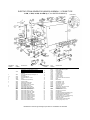
ITEM
QTY
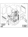
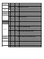
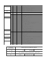
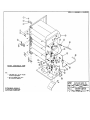
TUBE, ASSEMBLY, CONVECTION STEAMER
NUT, HEX 1/4-20 S/S
PIN, RACK
NUT, HEX 10-24 S/S
RING, SNAP S/S
HINGE, DOOR
CONVECTION STEAMER BODY HINGE-LEFT ASSEMBLY
PIN, HINGE
WASHER, LOCK MEDIUM PATTERN 5/16 S/S
BOLT, HEX 5/16-24 S/S
INSULATION, CONVECTION BODY WRAP
PANEL, TOP SHEETING ASSY.
PANEL, LEFT-SIDE OUTER CONV. STMR.
PART #
DESCRIPTION
TOLERANCES
CLEVELAND RANGE INC.
1333 East 179th St. Cleveland, Ohio 44110-2574
(EXCEPT AS NOTED)
DECIMAL
1 N/A
SCALE
N/A
ANGULAR
1 N/A
DRAWN BY:
P.J.D.
APPROVED
BY:
TITLE
CK
DATE
07-15-91
FINAL ASSEMBLY CONVECTION
MECHANICAL HINGE LEFT
DRAWING NO.
D-104516
REV.
-
SEE NOTE 2
LET. REVISIONS DATE
85
4
84
4
83
4
82
8
81
2
80
REF.
SEE NOTE 2
SEE NOTE 2
SEE NOTE 2
SEE NOTE 2
SEE NOTE 1
SEE NOTE 2
79
78
77
76
75
74
73
72
71
70
69 A/P
68
67 A/P
66
65 A/P
64
63
62
61
60
59
58
57
56
55
54
53
52
51
50
49
48
47
46
45
44
43
42
41
40
39
2
1
1
1
1
1
4
4
4
1
2
2
2
2
2
2
2
3
1
1
2
4
1
1
1
1
7
1
1
1
1
1
1
2
2
1
2
BY
101774 INSERT, BRASS FOR 1/4" POLY TUBE
104612 FOAM, TAPE 1/4 X 1/4 X 12-3/4
104613 FOAM, TAPE 1/4 X 1/4 X 3-3/4
15203 "O" RING, 3/8 I.D. X 1/2 O.D.
14919 LABEL, CAUTION HOT DOORS AND HANDLES
104210 SHIELD, HEAT, TABLETOP CONVECTION
104591 SHEILD ASSEMBLY, 900MM, 1050MM, LG, GAS
104590 SHEILD ASSEMBLY, 600MM, 900MM, 1050M, SM, GAS
23120 WASHER, FLAT 3/8 X 7/8
104123 LABEL, LADDER DIAGRAM
10222333000 TUBE, UPPER COMPT. CONDENSER
10222332400 TUBE, LOWER COMPT. CONDENSER
103885 HARNESS WIRING MECHANICAL
66014 PANEL, RIGHT-SIDE CONV. STMR.
41423 RACK, PAN SLIDE, 20"
23149 WASHER-NYLON, TYPE 6/6
14649 NUT, HEX, 1/2-13
0908 LUBRICANT "O" RING
70769 TUBE, COPPER TRAP TO DRAIN - LOWER
01205 ADHESIVE, LOCKTITE #290
06233 FITTING, COMPRESSION 3/8 T X 1/8/ MPT 90°
00932 SEALANT, RTV
56519 FITTING, COMPARTMENT DRAIN
02139 BEND, "Y", BLACK
06216 FITTING, COMPRESSION 1/4 T X 1/4 MPT STRAIGHT
06230 FITTING, COMPARTMENT DRAIN
14555 NOZZLE, SPRAY, BRASS 1/8" FULL JET
70732 TUBE, COPPER - DRAIN VENT
06192 FITTING, TUBE 1/4 T X 1/8 MPT 90°
70770 TUBE, COPPER, STEAMBOX TO TRAP - LOWER
70758 TUBE, COPPER, TRAP TP DRAIN - UPPER
20559 TRAP, 1/4 X 1/4 THERMOSTATIC
14681 NUT, COMPRESSION, FITTING, BRASS, 1/4" TUBE
70728 TUBE, COPPER, STEAMBOX TO TRAP - UPPER
06203 FITTING, COMPRESSION 1/2 T X 3/8 MPT 90°
104128 INSULATION, CONVECTION BODY REAR
69239 PANEL, REAR OUTER, SHEETING CONV. STMR.
19287 SCREW, TRUSS HEAD, SHEET METAL
70734 TUBE, STEAM SUPPLY - LOWER COMPARTMENT
06202 FITTING, COMPRESSION 1/2 T X 3/8 MPT ST.
70735 TUBE, STEAM SUPPLY - LOWER COMPARTMENT
423951 STEAM, INLET ASSEMBLY
03197 CLAMP, 1 HOLE, 3/4"
44064 WATER VALVE ASSEMBLY NEW CONV. STMR.
19147 SCREW, PAN HD STLD 8-32 S/S
23114 WASHER, INTERNAL TOOTH LOCK S/S #10
52598 BRACKET, VALVE, SUPPORT CONV. STMR.
104409 CLOSURE, THERMAL OPENING
14.
REF.
38
37
36
35
REF.
REF.
SEE NOTE 2-
SEE NOTE 2-
SEE NOTE 2-
SEE NOTE 2-
14652 NUT, HEX 5/16-18 S/S
104398 LABEL, WIRING SCHEMATIC
23134 WASHER, FLAT 5/16"
407491 PEDESTAL, WELDMENT HINGE-RIGHT
70081 TABLETOP HINGE RIGHT 900MM
34
70083 TABLETOP HINGE RIGHT 1050MM
70084 TABLETOP HINGE LEFT AND RIGHT 600MM
33
19196 SCREW, HEX HD, 5/16 X 18 X 3/4
32
8
14679 NUT, ACORN 10-24 S/S
31
2
19148 SCREW, HEX,WASH HD
30
1
44168 TERMINAL BLOCK ASSEMBLY 2 POLE
29
2
104223 NUT, HEX 6-32 ELASTIC LOCK
28
101051 NEVER-SEEZ
27
6
101873 NUT, HEX 1/4-20 ELASTIC LOCK
26
7
23105 WASHER, LOCK S/S 1/4"
25
11
23118 WASHER, FLAT S/S 1/4"
24
5
19288 SCREW, HEX HEAD 1/4-20
23
1
1025691 PANEL, FRONT FILLER
22
2
104501 TIMER ASSY. CONVECTION STEAMER MECHANICAL
21
2
1035372 DOOR, OUTER ASSEMBLY HINGE RIGHT
20
2
104101 DOOR, INNER ASSEMBLY
19
2
104046 CATCH, DOOR
18
4
14695 NUT, DOOR CATCH MOUNTING S/S
17
2
146771 NUT, ACORN 1/4-20
16
2
69298 SCREEN, COMPARTMENT DRAIN
15
2
102513 WASHER, FLAT S/S 5/15 X 3/4 X .080
14
8
101471 PIN, STEAMTUBE SUPPORT
13
8
41212 TUBE, ASSEMBLY, CONVECTION STEAMER
12
21
14618 NUT, HEX 1/4-20 S/S
11
16
101305 PIN, RACK
10
8
14659 NUT, HEX 10-24 S/S
9
4
104062 RING, SNAP S/S
8
4
104076 HINGE, DOOR
7
1
103558 CONVECTION STEAMER BODY HINGE - RIGHT ASSEMBLY
6
4
104077 PIN, HINGE
5
8
23106 WASHER, LOCK MEDIUM PATTERN 5/16 8/9
4
8
02312 BOLT, HEX HEAD 5/16-24 S/S
3
1
104125 INSULATION, CONVECTION BODY WRAP
2
1
66015 PANEL, TOP SHEETING ASSY.
1
1
66023 PANEL, LEFT - SIDE OUTER CONV. STMR.
ITEM QUANTITY PART NO.
DESCRIPTION
1
2
1
Cleveland Range inc.
1300 East 179th Street, Cleveland, Ohio 44110-2514
TOLERANCES
EXCEPT AS NOTED
DECIMAL
±
N/A
SCALE
ANGULAR
±
N/A
TITLE
DRAWN BY
.333”
-
FINAL ASSEMBLY CONVECTION MECHANICAL – HINGE RIGHT
DATE
OK
APPROVED BY
DUTCHMAN
11-04-91
DRAWING NO.
D-104520 PAGE 1 OF 2
REV.
-
LET.
-
REF
REF
REF
See
Note #1
86
85
84
83
82
81
80
79
78
{
{
REF. ------REF. -------
77
76
75
74
73
72
71
70
69
68
67
66
65
64
63
62
61
60
59
58
57
56
55
54
53
52
51
50
49
48
47
46
45
44
43
42
41
40
39
38
37
36
35
REF. -------
34
REF. -------
33
32
31
30
29
28
27
REF. -------
Revisions
PRODUCTION RELEASE E.O WC-1997
4
101774
INSERT, BRASS FOR 1/4" 0.0. POLY TUBE
A/R
00932
SEALANT, RTV
4
104612
FOAM, TAPE 1/4 X 1/4 X 13
4
104613
FOAM, TAPE 1/4 X 1/4 X 3 1/2
8
15203
"O" RING, 3/8 I.D. X 1/2 O.D.
A/R
01205
ADHESIVE, LOCKTITE #290
1
14919
LABEL, CAUTION HOT DOORS AND HANDLES
104210
SHIELD, HEAT - TABLETOP
104591
SHIELD, ASSY., 900MM, 1050MM, LG, GAS
104590
SHIELD, ASSY., 600MM, 900MM, 1050MM SM. GAS
1
104124
LABEL, LADDER DIAGRAM
1
1022333000 TUBE, UPPER COMPT. CONDENSER X 30'
1
10223332400 TUBE, LOWER COMPT. CONDENSER X 24'
1
104189
HARNESS WIRING NCC TIMER
1
66014
PANEL, RIGHT-SIDE CONV, STMR
4
41423
RACK, PAN SLIDE, 20'
4
23149
WASHER-NYLON, TYPE 6/6
4
14649
NUT, HEX 1/2-13, ZINC PLTD
A/R
00908
LUBRICANT, "O" RING
1
102154
TUBE, COPPER TRAP TO DRAIN - LOWER
1
06190
FITTING, COMPRESSION 1/4 T X 1/8 MPT STRAIGHT
2
06233
FITTING, COMPRESSION 3/8 T X 1/8 MPT 90°
1
05227
ELBOW, 1" STREET BLACK 45
2
56519
FITTING, COMPARTMENT DRAIN, 2 HOLE
2
02139
BEND, 'Y', BLACK
2
06216
FITTING, COMPRESSION 1/4 T X 1/8 MPT STRAIGHT
2
06230
FITTING, COMPARTMENT DRAIN
2
14555
NOZZLE, SPRAY, BRASS 1/8" FULL JET
2
70732
TUBE, COPPER - DRAIN VENT
3
06192
FITTING, TUBE 1/4 X 1/8 MPT 90°
1
70776
TUBE, COPPER, STEAMBOX TO TRAP - LINER
1
70758
TUBE, COPPER, TRAP TO DRAIN - UPPER
2
20559
TRAP, 1/4 X 1/4 THERMOSTATIC
4
14661
NUT, COMPRESSION, FITTING, BRASS, 1/4" TUBE
1
70726
TUBE, COPPER, STEAMBOX TO TRAP - UPPER
1
06203
FITTING, COMPRESSION 1/2 T X 3/8 MPT 90°
1
104126
INSULATION, CONVECTION BODY REAR
1
69239
PANEL, REAR OUTER, SHEETING CONV. STNR.
7
19267
SCREW, TRUSS HEAD, SHT. METAL
1
70734
TUBE, STEAM SUPPLY - LOWER COMPARTMENT
1
06202
FITTING, COMPRESSION 1/2 T X 3/8 MPT ST
1
70735
TUBE, STEAM SUPPLY - UPPER COMPARTMENT
1
423951
STEAM, INLET ASSEMBLY
1
03197
CLAMP, 1 HOLE, 3/4"
1
44064
WATER VALVE ASSEMBLY NEW CONV. STNR.
2
19147
SCREW, PAN HD STLD 8-32 S/S
2
100711
WASHER, INTERNAL TOOTH LOCK S/S #8
1
52598
BRACKET, VALVE, SUPPORT CONV. STNR.
2
19972
SWITCH, THERMAL
14652
NUT, HEX 5/16-18 S/S
1
104397
LABEL, WIRING SCHEMATIC
23134
WASHER, FLAT 5/16"
1
40749
PEDESTAL, VELOMENT HINGE-LEFT
70085
TABLETOP HINGE LEFT 900MM
70082
TABLETOP HINGE LEFT 1050MM
70084
TABLETOP, HINGE LEFT & RIGHT 600MM
19196
SCREW, HEX HD. 5/16 X 18 X 3/4
8
14679
NUT, ACORN 10-24 S/S
19148
SCREW, HEX WASH HEAD, SHEET METAL
1
44168
TERMINAL BLOCK ASSEMBLY 2 POLE
2
104223
NUT, HEX 6-32 ELASTIC LOCK
A/R
101051
HEVER - SEEZ
6
14665
NUT, HEX 1/4-20 ELASTIC LOCK W/ NYLON INSERT
Date
09-30-91
BY
PD
26
5
25
13
24
5
23
1
22
2
21
2
20
2
19
2
18
4
17
2
16
2
15
2
14
8
13
8
12
21
11
16
10
8
9
4
8
4
7
1
6
4
5
8
4
8
3
1
2
1
1
1
ITEM QTY
TOLERANCES
23105
23116
19288
1025691
104500
103537
104101
104046
14695
146771
69298
102513
101471
41212
14618
101305
14659
104062
104076
103557
104077
23106
02312
104125
66015
66023
PART #
WASHER, LOCK S/S 1/4"
WASHER, FLAT S/S 1/4"
SCREW, HEX HEAD 1/4-20
PANEL, FRONT FILLER
TIMER ASSY. CONVECTION STEAMER ELECTRICAL
DOOR, OUTER ASSEMBLY HINGE LEFT
DOOR, INNER ASSEMBLY
CATCH, DOOR
NUT, DOOR CATCH MOUNTING S/S
NUT, ACORN 1/4-20
SCREEN, COMPARTMENT DRAIN
WASHER, FLAT S/S 5/15 X 3/4 X .000
PIN, STEAMTUBE SUPPORT
TUBE, ASSEMBLY, CONVECTION STEAMER
NUT, HEX 1/4-20 S/S
PIN, RACK
NUT, HEX 10-24 S/S
RING, SNAP S/S
HINGE, DOOR
CONVECTION STEAMER BODY HINGE-LEFT ASSEMBLY
PIN, HINGE
WASHER, LOCK MEDIUM PATTERN 5/16 S/S
BOLT, HEX HEAD 5/16-24 S/S
INSULATION, CONVECTION BODY WRAP
PANEL, TOP SHEETING ASSY.
PANEL, LEFT-SIDE OUTER CONV. STNR.
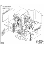
DESCRIPTION
CLEVELAND RANGE INC.
(Except as noted)
th
1333 East 179 St. Cleveland, Ohio 44110-2574
DECIMAL
N/A
MODULAR
N/A
SCALE
DRAWN BY
N/A
TITLE
FINAL ASSEMBLY CONVECTION
ELECTRICAL HINGE LEFT
DATE
CK
APPROVED BY
P.J.O.
DRAWING NO.
07-16-91
D-104517
REV.
-
84
83
82
81
80
79
78
77
4
4
4
A/R
8
2
-
101774
104812
104813
101051
15203
14919
104210
104591
104590
76
75
74
73
72
71
70
69
68
67
66
65
64
63
62
61
60
59
58
57
56
55
54
53
52
51
50
49
48
47
46
45
44
43
42
41
40
39
38
37
36
35
34
1
1
1
1
4
4
4
A/R
1
A/R
2
1
2
2
2
2
2
2
3
1
1
2
4
1
1
1
1
1
1
1
1
1
1
1
1
2
1
2
1
2
1
8
1
2
A/R
6
5
11
5
1
2
2
2
2
4
2
2
2
8
8
21
16
1022333000
1022332400
104189
66014
41423
23149
14549
00908
102154
01205
06233
104224
58519
02139
06216
06230
14555
70732
06192
70770
70758
20559
14881
70728
06203
104128
69239
19287
70734
06202
70735
423951
03197
44064
18147
23114
52598
104409
14852
104398
23134
407491
70081
70083
70084
19198
14879
18148
44168
104223
101051
101873
23105
23118
19288
1025891
104501
1035372
104101
104048
4695
46771
69298
102513
101471
41212
14816
101305
33
32
31
30
29
28
27
26
25
24
23
22
21
20
19
18
17
16
15
14
13
12
11
INSERT, BRASS 1/4" POLY TUBE
FOAM, TAPE 1/4 X 1/4 X 12-3/4
FOAM, TAPE 1/4 X 1/4 X 3-3/4
NEVER-SEEZ
"O" RING, 3/8 I.D X 1/2 O.D.
LABEL, CAUTION HOT DOORS AND HANDLES
SHEILD, HEAT, TABLETOP CONVECTION
SHEILD ASSEMBLY, 900MM, 1050MM, LG GAS
SHEILD ASSEMBLY, 600MM, 900MM,1050MM SM
GAS
TUBE, UPPER COMPT. CONDENSER
TUBE, LOWER COMPT. CONDENSER
HARNESS WIRING NOC TIMER
PANEL, RIGHT-SIDE CONV. STMR.
RACK, PAN SLIDE, 20"
WASHER-NYLON, TYPE 6/8
NUT, HEX, 1/2-13
LUBRICANT "O" RING
TUBE, COPPER TRAP TO DRAIN-LOWER
ADHESIVE, LOCKTITE #290
FITTING, COMPRESSION 3/8 T X 1/8 MPT 90°
LABEL, LADDER DIAGRAM
FITTING, COMPARTMENT DRAIN
BENS, "Y" BLACK
FITTING, COMPRESSION 1/4 T X 1/4 MPT STRAIGHT
FITTING, COMPARTMENT DRAIN
NOZZLE, SPRAY, BRASS 1/8" FULL JET
TUBE, COPPER-DRAIN VENT
FITTING, TUBE 1/4 T X 1/8 MPT 90°
TUBE, COPPER, STEAMER TO TRAP-LOWER
TUBE, COPPER, TRAP TO DRAIN-UPPER
TRAP, 1/4 X 1/4 THERMOSTATIC
NUT, COMPRESSION, FITTING, BRASS, 1/4" TUBE
TUBE, COPPER, STEAM BOX TO TRAP-UPPER
FITTING, COMPRESSION 1/2 T X 3/8 MPT 90°
INSULATION, CONVECTION BODY REAR
PANEL, REAR OUTER, SHEETING CONV. STMR.
SCREW, TRUSS HEAD, SHEET METN.
TUBE, STEAM SUPPLY-LOWER COMPARTMENT
FITTING, COMPRESSION 1/2 T X 3/8 MPT ST
TUBE, STEAM SUPPLY-UPPER COMPARTMENT
STEAM, INLET ASSEMBLY
CLAMP, 1 HOLE, 2/4"
WATER VALVE ASSEMBLY NEWCONV. STMR.
SCREW, PAN HD STLD 8-32 S/S
WASHER, INTERNAL TOOTH LOCK S/S #10
BRACKET, VALVE, SUPPORT CONV. STMR
CLOSURE, THERMAL OPENING
NUT, HEX 5/18-18 S/S
LABEL, WIRING SCHEMATIC
WASHER, FLAT 5/16"
PEDESTAL, WELDMENT HINGE-RIGHT
TABLETOP HINGE RIGHT 900MM
TABLETOP HINGE RIGHT 1050MM
TABLETOP HINGE LEFT & RIGHT 600MM
SCREW, HEX HD. 5/18 X 18 X 3/4
NUT. ACORN 10-24 S/S
SCREW, HEX WASH HD.
TERMINAL BLOCK ASSEMBLY 2 POLE
NUT, HEX 6-32 ELASTIC LOCK
NEVER-SEEZ
NUT, HEX 1/4-20 ELASTIC LOCK
WASHER, LOCK S/S 1/4"
WASHER, FLAT S/S 1/4"
SCREW, HEX HEAD 1/4-20
PANEL, FRONT FILTER
TIMER ASSY, CONVECTION STEAMER MECH.
DOOR, OUTER ASSEMBLY HINGE RIGHT
DOOR, INNER ASSEMBLY
CATCH DOOR
NUT, DOOR CATCH MOUNTING S/S
NUT, ACORN 1/4-20
SCREEN, COMPARTMENT DRAIN
WASHER, FLAT S/S 5/15 X 3/4 X .080
PIN, STEAMTUBE SUPPORT
TUBE, ASSEMBLY, CONVECTION STEAMER
NUT, HEX 1/4-20 S/S
PIN, RACK
10
9
8
7
6
5
4
3
2
1
8
4
4
1
4
8
8
1
1
1
ITEM QTY
14659
104062
104078
103558
104077
23106
02312
104125
66015
66023
PART
NO.
NUT, HEX 10-24 S/S
RING, SNAP S/S
HINGE, DOOR
CONVECTION STEAMER BODY HINGE-RIGHT ASS.
PIR. HINGE
WASHER, LOCK MEDIUM PATTERN 5/16 S/S
BOLT, HEX HEAD 5/18-24 S/S
INSULATION, CONVECTION BODY WRAP
PANEL, TOP SHEETING ASSY.
PANEL, LEFT-SIDE OUTER CONV. STMR.
DESCRIPTION
TOLERENCES
CLEVELAND RANGE INC.
(EXCEPT AS
1130 East 179th St. Cleveland, Ohio 44110-2574
NOTED)
DECIMAL
SCALE
DRAWN BY:
APPROVED BY:
N/A
N/A
P.J.D.
ANGULAR
TITLE
FINAL ASSEMBLY CONVECTION
N/A
ELECTRICAL HINGE RIGHT
DATE
DRAWING NUMBER
REV.
CK
11-05-91
0-104521 PAGE 1 of 2
-
DIRECT STEAM KETTLE
CARE AND CLEANING
OPERATION
Ensure that there is an adequate steam supply
to the kettle.
Turn the steam control valve to the fall open
position by turning the knob counter-clockwise,
then allow the kettle to pre-heat.
Your kettle must be cleaned regularly to maintain
its fast, efficient cooking performance, and to
ensure its continued safe, reliable operation.
WARNING: Do not use chlorine base detergent.
1.
NOTE: "When cooking egg and milk products,
the kettle should NOT be preheated, as products
of this nature adhere to hot cooking surfaces.
These types of foods should be placed in the
kettle before hearing is begun.
Prepare a warm water and mild detergent
solution in the kettle.
2.
Remove food son inside- die kettle using a
nylon brush, Do not use a metal bristle
brush, as this may permanently damage the
kettle's stainless steel surface.
Fill kettle with product to desired level
3.
Loosen food which is stuck to the kettle by
allowing it to soak at a low temperature
(simmer or low boil).
4.
Tilt kettle forward to drain the •wash water.
5.
Rinse the kettle interior thoroughly, then
drain rinse water.
6.
Leave the cover and draw-off valve open
when the kettle is not in use.
7.
Using mud soapy water and a damp
sponge, wash the exterior of the kettle,
rinse, and dry.
"When the produce has reached the desired
temperature, regulate the heat, as required, by
turning the steam control valve for less steam
and therefore, a lower temperature.
When cooking is complete, dose the steam
control valve by turning the knob.
For kettle/steamer combinations: If the boner in a
steamer is supplying steam to a kettle, always
heat the kettle first. After the kettle contents are
heated, and the boiler's steam pressure returns
to normal the steamer may be used. Pressure
steamer compartments should be sequentially
started, and preheated before cooking.
NOTE: As with cleaning food soil from any
cookware, an important pan of kettle cleaning is
to prevent foods from drying on. For this reason,
cleaning should be completed immediately after
cooked foods arc removed. Please refer to the
"Care and Cleaning instructions for detailed
kettle washing procedures.
NOTE: For more difficult cleaning applications, one
of die following can be used: alcohol, baking soda,
vinegar, or a solution of ammonia in water. Avoid
the use of chloride cleansers, which may damage
the kettle's stainless steel surface.
WARNING: Steel wool should never be used for
cleaning the cooking chamber of the kettle.
Particles of steel wool become embedded in the
cooking surface and rust, and may corrode the
stainless steel.
234-03TE
STEAM CONTROL
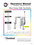
PARTS LIST - STEAM CONTROL
ITEM NO.
PART NO.
DESCRIPTION
QTY.
1.
KE50458
End cap, condensate return
1
2.
KE50455-1
Trunnion, condensate return
1
3.
KE50456
Trunnion, housing
2
4-10.
SE00011
Steam inlet Trunnion assy.
1
4.
FA00017
"O" Ring
2
5.
FA00117
"O" Ring
4
6.
KE50460-1
Trunnion, steam inlet
1
7-10.
7.
SE00029
FA11089
Operating stem assy. stainless steel
Screw, 8-32x1/4-
1
1
8.
KE51713
Washer, operating stem
1
9.
FA00110
"0"Ring
1
10.
KE50459
Operating stem, stainless steel
1
11.
12.
KE50457
FA11054
End cap, steam inlet
Screw, 6-32 x 3/8"
1
2
14.
SE00028
Steam inlet knob assy.
1
15.
FA11092
Screw, 8-32 x 1/2"
1
16.
KE00200
Leg weldment ( 1 gal model)
2
KE00197
KE00198
Leg weldment ( 6 gal model)
Leg weldment (12 gal model)
2
2
KE00199
Leg weldment (20 gal model)
2
KE50465
KE52030
Service pipe ( 1 gal model)
Service pipe ( 6 gal model)
2
2
KE50463
KE50464
Service pipe (12 gal model)
Service pipe (20 gal model)
2
2
18.
KE50467
Washer, foot
2
19.
FA30502
Washer, satin coal
2
20.
KE51898
Washer, lock
2
21.
FI00222
Lock nut, 1/2 NPS
2
22.
KE50475
Plug button
1
23.
KE50886
Handle ( 1 gal model)
1
SK50051
Handle ( 6,12 gal model)
1
KE50803
Handle (20 gal model)
1
24.
KE50151
Knob
1
25.
KE50474
Foot
1
17.
OPERATING CONTROLS
For your better understanding and confidence, the following explanation of the control system on this
kettle is offered.
ITEM NO.
DESCRIPTION
FUNCTION
14
Steam Inlet Knob
Toms the steam on or off to the kettle.
23-24
Tilting Handle
Used for tilting the kettle.
SERVICING GUIDE
This section contains information intended for use by Authorized Service Personnel only.
A/ PROBLEM : Kettle heats too slowly or does not come to a boil.
Probable Cause
Remedy
1.
Inadequate steam flow.
Check for correct steam using chart below.
If kettle is connected to a -steamer and
powered by a generator the units should be
operated sequentially (kettle boiling first,
then start steamer).
2.
Steam trap not operating property.
The trap should open periodically to dump
condensate, then close, If it does not open
or dose it should be cleaned or replaced.
3.
Food batches are not always the same.
When checking make certain that the
original state (ie. fresh or frozen) and
quantity of food product is the same.
B/ PROBLEM : The trunnion housing leaks steam.
1.
Probable Cause
Remedy
Trunnion "O" rings are worn.
Replace "O" rings.
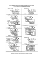
STEAM FLOW RATING
OF STEAM GENERATORS
GAS INPUT
BTU/HOOR
100,000
160,000
200.000
250000
300,000
ELECTRIC
KW INPUT
18 KW
24 KW
27 KW
36 KW
48 KW
STEAM FLOW RATE
REQUIREMENTS FOR KETTLES
STEAM OTJTPCT
LB&/HOUR
60
95
325
150
ISO
BOILER
BS.
1.7
2£
3.6
4.4
52
60
70
90
320
250
1.7
20
26
35
43
Capacity
GaL./Lit.
Fast
Cooking
Medium Speed
Cooking
Studs.
Kettle
5/17
10/42
25/95
40/151
60/227
11
22
55
88
132
9
18
44
70
105
6
11
28
44
66
Note: Above shows lbs. per hour with 10-15 psig
steam at the kettle. The use of higher steam
pressures (20-25 psig) will reduce heat-up time
5 to 20 %.
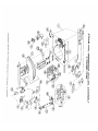
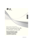
ELECTRIC STEAM GENERATOR (BOILER) ASSEMBLY - 2 PROBE TYPE
18 KW, 27 KW, 36 KW, & 48 KW (2, 3, & 4 HEATER ELEMENTS)
( OPTIONAL)
REFERENCE
NUMBER
1
PART
NUMBER
43894
44149
2
40421
23
3
4
5
6
7
43748
07106
40462
101466
52305
40445
07108
23132
07302
08235
08236
08237
08234
08241
08242
08243
08244
08165
08166
08167
08163
08214
08215
8
9
DESCRIPTION
Electric Boiler Shell only, with legs, hand hole
plate assembly, mounting studs for 3" squareflanged heater elements
Electric Boiler Shell (43894) above, also including
sight gauge, two probes and extensions with
cover box.
Hand Hole Plate Assembly including bar. nut.
and gasket.
Hand Hole Plate only
Hand Hole Gasket. 4'" x 6" oval
Probe
Probe Extension Set (set of two)
Probe Cover Box
Water Gauge Set with Glass
Fiber Washer (2 required)
Gauge Glass Washer (2 required)
Gauge Glass Only. 6" long
Heater. 9 KW. 208 volt. 3 phase
Heater. 9 KW. 220/240 volt 3 phase
Heater. 9 KW. 440/480 volt. 3 phase
Heater. 9 KW. 600 volt 3 phase
Heater. 9 KW. 208 won. 1 phase
Heater. 9 KW. 220/240 volt. 1 phase
Heater. 9 KW. 440/480 volt. 1 phase
Heater. 9 KW. 600 volt. 1 phase
Heater. 12 KW. 208/220 vott. 3 phase
Heater. 12 KW. 230/240 volt. 3 phase
Heater. 12 KW. 440/480 volt. 3 phase
Heater. 12 KW. 600 volt 3 phase
Heater. 12 KW. 208/220 volt. 1 phase
Heater. 12 KW. 230/240 volt. l phase
REFERENCE
NUMBER
10
1
1
12
13
14
15
16
17
18
19
20
21
22
23
24
25
26
27
28
29
30
31
32
33
34
35
36
PART
NUMBER
08216
08217
07128
16546
22131
22130
19947
03509
03506
23198
03524
03525
44168
03202
20478
20535
22102
03276
22223
19870
03277
22221
13252
45006
41943
05253
02623
19995
19993
19994
07167
DESCRIPTION
Heater. 12 KW. 440/480 volt 1 phase
Heater. 12 KW. 600 volt. 1 phase
Heater Gasket:
3" Block-Off Plate
15 psi Safety Valve
8 psi Safety Valve
Pressure Switch
Contactor. 50 amp
Contactor. 75 amp
Control Board. water level and LWCO
Relay
Relay Socket
Terminal Block. 2 pole
Circuit Breaker, 1 amp
Interval Timer. 3 minute
Transformer. 150 VA
Cheek Valve. 1/4"
1/4" Ball Valve, water supply shut-off
Solenoid Valve, water feed
Line Strainer, 1/4"
1/4" Ball Valve, manual drain
Solenoid Valve, boiler drain
Drain Manifold
Low Water Cut-Off Assembly (California only)
LWCO Mounting Plate (California only!
Brass Street Elbow (California only)
Reducing Bushing. 1/2' • 1/4" (California only)
Float Switch. LWCO (California only)
DPDT Power switch
SPST Momentary contact reset switch
Pressure gauge. 0-30 psi. 1 1/2 "
Manufacturer reserves right of design improvement or modification as warranted.
HEATER AND CONTACTOR WIRING SCHEMATICS FOR SOLID
STATE ELECTRIC STEAM GENERATORS
Manufacturer reserves right of design improvement or modification, as warranted.
Electric Models with Secondary Low Water Cutoff Built to California Code
GAS STEAM GENERATOR (BOILER) ASSEMBLY - 2 PROBE TYPE SMALL: 100,000
BTU (2 Burners) & 200,000 BTU (4 burners) LARGE: 250,000 BTU (5 burners) &
300,000 BTU (6 burners)
REFERENCE
NUMBER
PART
DESCRIPTION
NUMBER
1
43898
43899
44173
44172
2
40421
Small boiler shell only (100.000/200.000 BTU). with
legs. studs. Hand hole plate assembly and top flue
bracket.
Large boiler shell only (250.000/300.000 BTU), with
legs. studs. hand hole plate assembly. and top flue
bracket.
Small boiler shell (43898) above, also including
insulation panels, top flue collector with insulation,
sight gauge, two probes and extensions with cover
box.
Hand hole plate assembly including bar. nut, and
gasket.
43748
Hand note Plate only
3
07106
Hand hole gasket. 4' x 6' oval
4
40462
Probe
5
101466
Probe extension set (set of two)
6
52305
Probe cover box
40445
07108
PART
NUMB
ER
44156
DESCRIPTION
44157
6-burner rear burner support
22130
Safety valve. 6 psi
22131
Safety valve. 15 psi
16
19947
Pressure switch
17
22228
Gas control valve, natural gas. small boiler
(100.000/200.000 BTU)
22230
Gas control valve. natural gas. large boiler
(250/300.000 BTU)
22231
Gas control valve. L.P. gas. small and large boilers
(100.000/200.000 and 250,000/300.000 BTU)
18
44169
Igniter cable
19
44096
Igniter box assembly with ignitor
20
05101
Igniter electrode
21
40918
Gas manifold. 2 -burner
40920
Gas manifold. 4 -burner
40921
Gas manifold. 5 -timer
40922
Gas manifold. 6 -burner
22
52602
Manifold alignment bracket
23
24 25
19632
15453
15450
02497
Orifice holder
Burner orifice, natural gas
15
Large boiler shell (43899) above, also including
insulation panels, top flue collector with insulation.
sight gauge, two probes and extensions with cover
box.
2a
7
REFERENCE
NUMBER
Water gauge set with glass
Fiber washer (2 required)
5-burner rear burner support
23132
Gauge glass washer (2 required)
8
07302
Gauge glass only 6' long
9
44043
Left side insulation panel assembly
440431
Left side insulation panel assembly for LP. gas 100.000/200.000 BTU boiler only
26
03546
Spark ignition control module
44042
Right side insulation panel assembly
440421
Right side insulation panel assembly for LP. gas 100.000/200.000 BTU boiler only
27
28
20528
20478
24 volt transformer
Internal time 3 minute
29
44164
Terminal block- 4 pole
42398
Top flue collector with insulation, for small boiler
(100.000/200.000 BTU)
30
03525
Relay socket
31
03524
Relay
42399
Top flue collector with insulation, for large boiler
(250.000/300.000 BTU)
32
23198
42360
Internal flue riser assembly for small boiler
(100.000/200.000 BTU)
33
22102
Control board, water level and IWCO
Check valve. 1/4"
34
03276
1/4" Ball valve, water supply shut off
42361
Internal flue riser assembly for large boiler
(250,000/300.000 BTU)
35
36
22223
19870
Solenoid valve, water feed
Line strainer. 1/4"
44134
2-burner front baffle assembly - natural gas
37
03277
1/4" Ball valve, manual drain
44135
4-burner from baffle assembly - natural gas
38
22221
Solenoid valve, boiler drain
40840
5-burner front baffle assembly - natural gas
39
13252
Drain manifold
40842
6-bumer front baffle assembly - natural gas
40
45006
Low water cut-off assembly (California only)
44150
Front burner baffle assembly for LP. gas 100.000/200.000 BTU boiler only (not shown)
41
41943
LWCO mounting plate (California only)
42
07128
Gasket (California only)
Right side burner baffle assembly for L.P. gas
100.000/200.000 BTU boiler only (not shown)
43
05253
Brass street elbow (California only)
44
02623
1/2"-1/4" Brass reducing bushing (California only)
45
19995
Float switch. IWCO (California only)
46
47
19993
19994
DPOT Power switch
SPST Momentary contact reset switch
48
07167
Pressure gauge. 0-30 psi. 1 l/2"
10
11
13
44170
14
44171
Left side burner baffle assembly for L.P. gas
100.000/200.000 BTU boiler only (not shown)
44153
2-bumer rear burner support
44155
4-bumer rear burner support
Burner orifice. L.P. gas Burner
Manufacturer reserves right of design improvement or modification, as warranted.
STEAM COIL GENERATOR (BOILER) ASSEMBLY 2 PROBE
TYPE
REFERENCE NUMBER
1
PART NUMBER
43977
2
2a
3
4
5
6
7
8
100636
16545
07116
40401
14612
23135
14611
40446
07108
23132
07301
52305
40462
101466
22130
22131
22232
03277
22193
19872
20555
19870
06226
22223
22102
03276
22221
03277
03616
13252
05292
05238
23198
44165
03525
03524
20478
19947
19993
19994
07168
07166
45006
41943
07128
05253
02623
19995
9
10
11
12
13
14
15
16
17
18
19
20
21
22
23
24
25
26
27
28
29
30
31
32
33
34
35
36
37
38
39
40
41
42
43
44
45
DESCRIPTION
Steam Coil Boiler Shell with Legs, Sight Gauge, Steam
Coil, Hand Hole Plate Assembly, 2 Probes and
Extensions with Cover Box.
Hand Hole Plate Assembly
Hand Hole Plate Only
Hand Hole Gasket
Steam Coil Assembly
1 1/4" Brass Locknut
3 1/4 " Square Flat Washer
1 1/4 " Steel Locknut
Water Gauge Set with Glass
Fiber Washer (2 required)
Gauge Glass Washer (2 required)
Glass Only—10 1/2" Long
Probe Cover Box
Probe with Lockwasher and Screw
Probe Extension Set (2)
Safety Valve—8 psi
Safety Valve—15 psi
Safety Valve—55 psi
3/4" Ball Valve
3/4" Steam Solenoid Valve
3/4" Line Strainer
3/4" Bucket Trap
1/4" Line Strainer
Brass Elbow, 90°, Special
Solenoid Valve, Water Feed
Check Valve, 1/4'
3/4" Ball Valve, Water Supply Shut Off
Solenoid Valve, Boiler Drain
3/4" Ball Valve, Manual Drain
Reducing Bell
Drain Manifold
Street Elbow, 90°
Elbow , 90°
Control Board, Water Level and LWCO
Terminal Block, 4-pole
Relay Socket
Relay
Interval Timer, 3 Minute
Pressure Switch
DPDT Power Switch
SPST Momentary Contact Reset Sw itch
Pressure Gauge, Back Mount, 0-30 psi
Pressure Gauge, Back Mount, 0-100 psi
Low Water Cut Off Assembly (California Only)
LWCO Mounting Plate (California Only)
Gasket (California Only)
Brass Street Elbow (California Only)
1/2"-1/4" Brass Reducing Bushing (California Only)
Float Switch. LWCO (California Only)
Manufacturer reserves right of design improvement or modification, as warranted
STEAM GENERATOR (2 PROBE TYPE) MAINTENANCE PROCEDURES
CAUTION: Service on the generator must be performed only by a trained and
experienced service technician, thoroughly familiar with servicing steam
generators. No work should be done on the steam generator while it is
pressurized or hot Be sure all energy sources are shut off before the start of
any work.
The steam generator must be drained under pressure (blowdown) after a maximum of 8 hours of use. It the generator's
feedwater contains more than 300 parts per million of total dissolved solids, the generator must have a blowdown after each 46 hours of use. "Blowdown" means the generator must be drained under pressure.
THE GENERATOR "BLOWDOWN" IS PERFORMED BY SHUTTING OFF THE UNITS RED-LIGHTED "POWER"
SWITCH WHILE THE GENERATOR IS AT NORMAL OPERATING PRESSURE. WHEN THE BOTTOM OF THE
"POWER" ROCKER SWITCH IS PUSHED. ITS RED LIGHT GOES OUT. AND THE DRAIN VALVE
AUTOMATICALLY OPENS, DRAINING THE GENERATOR. AN AUTOMATICALLY-TIMED SOLENOID VALVE
WILL FLUSH THE DRAIN FOR 3 MINUTES. THEN SHUT OFF. AFTER 3 MINUTES. THE UNIT CAN BE
RESTARTED.
Even though the "Blowdown" is performed faithfully each day. it will still be necessary to have a qualified service technician
periodically inspect the inside of the generator for scaling or pitting. The generator's hand hole plate should be removed at
regular intervals, so that it and the inside of the generator can be inspected. The hand hole plate should be cleaned and
examined each time it is removed. If the hand hole plate is chipped or cracked, or over three years old, install a new one. A
new hand hole gasket should always be installed.
Scaling indicates a high concentration of dissolved minerals in the feed water. Pitting indicates an excess acid condition. The
best way to reduce servicing time and to assure a long generator life is to provide feed water that is low in mineral content and
low in gas content. Water that is fit to drink can still be high in impurities that are highly detrimental to a steam generator.
Consult the state department of water for an on-the-premises water analysis and for recommendations concerning steam
generator feed water treatment (if required), in order to remove or reduce harmful concentrations of minerals.
CAUTION: Never tighten the hand hole plate nut when the steam generator is
in use, hot, or otherwise pressurized. Never tighten nut over 15 foot-pounds
torque. Over tightening may cause uneven stress, which may result in the
weakening and possible breakage of the plate.
The "Blowdown" procedure will not completely remove the mineral deposits that adhere to the top of the generator.
It will be necessary to periodically have scale accumulations removed from the inside of the steam generator by a qualified
service technician. Only a U.S.D.A. approved acid cleaner should be used to descale the generator.
Descaling should be done once a year. but in poor water (highly mineralized) areas it may be needed two or three times a year.
Failure to periodically remove scale from the inside of the generator will result in greatly reduced generator life.
Check the safety valve once a month while the steam generator is pressurized. Test by pulling the safety valve lever. The
valve must open freely and snap closed when released. If it does not. or if it drips constantly, a new safety valve is needed.
If the steam generator is to be left idle for three months or more. it should be drained and dried out and the hand hole plate left
off.
0485
CLEVELAND RANGE, INC., 1333 EAST 179th ST., CLEVELAND, OHIO 44110
LITHO IN U.S.A.
Manufacturer reserves right of design improvement or modification, as warranted.
WATER QUALITY REQUIREMENTS — 2-PROBE TYPE
STEAM GENERATOR PROTECTION AND MAINTENANCE
A steam generator, or boiler". unlike other types of water-using
kitchen equipment distills the water in order to make steam. Nearly
all feed-water sources contain dissolved minerals in varying
degrees of concentration. As this water is boiled, pure steam rises
from its surface. upward to the cooking compartment(s). leaving
minerals behind, that can become harmful to the steam generator.
If minerals are allowed to accumulate inside the steam generator.
they will solidify as a scale. Then. malfunctioning will occur, and
serious equipment damage may result
The use of good Quality generator feed water is the responsibility
of the owner/user. The use of poor quality feed water could void
equipment warranties. The mini-mum treatment required in most
areas is water softening, although local water conditions may
require more intensive pretreatment than simply a water softener.
Scale problems occur when feed water is high in hardness. total
dissolved solids, silica, and alkalinity. Water softening will only
reduce the water's hardness, which is the presence of dissolved
salts of magnesium and calcium. Water softening will not affect
the multitude of other minerals found in most water supplies.
Because generator scale is the result of the precipitation of many
minerals. the best property to control, for generator feed water, is
total dissolved solids, not just hardness.
The recommended minimum water quality standards. whether
untreated or pre-treated. based upon 8 hours of use per day. and a
Daily Blowdown are as follows:
TOTAL DISSOLVED SOLIDS
million TOTAL ALKALINITY
million SlLICA
million pH FACTOR
less than
60 parts per
less than
27 parts per
less than
13 parts per
greater than
7.5
Consult the state department of water or a local water treatment
specialist for an on-the-premises water analysis and for
recommendations concerning steam generator teed water treatment
(if required), in order to remove or reduce harmful concentrations
of minerals.
If the recommended water quality requirements are met without
supplemental treatment or if treatment is applied. resulting in feed
water quality meeting the prescribed standards, the steam generator
will need to be blown down only once every 8 hours. In addition.
the inside of the generator requires an inspection (for excessive
lime accumulation) only once every six months. Chemically
descale the generator as required.
If a ore-treatment unit cannot be installed, and the recommended
water quality requirements are not met the following procedures
should be followed, in order to achieve maximum steam generator
service life. The steam generator should be blown down after each
4-6 hours of use. Have the steam generator inspected, inside and
outside, by a qualified technician every three months. If the inside
of the generator is heavily coated with scale. have it chemically
descaled by a qualified service technician.
0485
INSTRUCTIONS FOR CHEMICALLY DESCALING 2PROBE TYPE STEAM GENERATORS
WARNING: Steam under pressure may cause serious
injury and bodily harm when it is acciden| tally or
carelessly released. Improper handling I of acid could
cause serious, permanent injury. Therefore, service of the
steam generator should only be performed by trained and
experienced personnel, thoroughly familiar with
servicing generators.
There are a number of commercial descaling chemicals
available, produced by various manufacturers. Those utilizing
a sulfamic acid base, which can be identified by its powdered
form are safe and compatible with our food preparation
equipment it is imperative that the acid used for descaling be
FDA approved, for use in food preparation equipment
Various manufacturers may include additional chemicals to
increase potency, and therefore. instructions for a specific
brand should be followed care-fully If instructions are not
provided with the deliming chemical you purchase, the
following general guidelines may be followed.
WARNING: Exercise care when handling acid. Avoid
contact with skin, eyes, or clothing. Wear safety glasses or
face shield, along with rubber gloves and rubber apron.
In case of exposure to clothing, remove clothing and flush
with water. In case of exposure to skin or eyes, flush with
water for 15 minutes and get immediate medical
; attention. Do not take internally. Keep out of the
' reach of children.
Be sure the generator has been drained, de-pressurized: and is
cool. Open the hand hole access plate on the front of the
generator and place approximately 8-10 pounds of sulfamic
acid inside the generator. Put a new hand hole gasket on the
hand hole plate, and replace the hand hole plate, tightening
the bar and nut assembly to a maximum of 15 foot pounds
torque. The generator must be completely filled with water
(fill the generator beyond its normal, automatic fill point of
2/3 up in the sight gauge). This can be accomplished by
temporarily disconnecting the wire from the water level probe
at the water level control board. The board is marked "HI" at
this connection point Turn the main on-off rocker switch to
the "ON" position, then close the manual water feed valve
when the generator is completely filled- Leave the on-off
rocker switch in the "on" position to prevent the generator
from automatically draining. Reconnect the probe wire to the
"HI" terminal of the water level control board. Let the
solution stand for several hours, then flush with water. Rinse
with a solution of bicarbonate of soda to neutralize any acid
residue, and again, flush with water. Be sure to reconnect the
wire to the water level control board and to open the manual
water feed valve.
CAUTION: Never tighten the hand hole plate nut when
the steam generator is in use, hot, or otherwise
pressurized. Never tighten nut over 15 foot pounds
torque. Over tightening may cause uneven stress, which
may result in the weakening and possible breakage of the
plate.
CLEVELAND RANGE, INC., 1333 EAST 179th ST., CLEVELAND, OHIO 44110
LITHO IN U.S.A.
Manufacturer reserves right of design improvement or modification, as warrantee.
Descaling Procedure for Two-Probe Steam Generators
The steam generator should be descaled at least once
a month, depending on scale buildup. If you have
serious steam generator scale buildup, install a water
treatment system for the steamer-Cleveland Range
recommends use of the descaling kit. part number
40891, which consists of powdered sulfamic add. Full
descaling may take several hours, or more than one
acid process. Perform descaling until all scale buildup
is cleaned out.
Follow hazard and leak cleanup procedures on add
container label. If the label is not readable or has been
removed, refer to the following hazard and emergency
instructions as a minimum safety precautionTHESE INSTRUCTIONS ARE FOR USE WITH
POWDERED SULFAMIC ACID ONLY.
• Health Hazard Data, Effects of Overexposure Product is extremely irritating to the eyes and may
result in eye burns. Product is severely irritating to
skin and can result in skin bums; repeated or
prolonged contact with more dilute solutions may
result in dermatitis. Aerosol mist or vapors are
irritating to respiratory tract, eyes and throat.
Prolonged exposure to high concentration may result
in pulmonary edema If ingested, may result in
abdominal hemorrhage with severe abdominal pain,
nausea, vomiting or loss of consciousness; necrosis
of stomach and gastrointestinal tract may also occur.
• Emergency and First Aid Procedures - In
case of eye contact, immediately flush eyes with
plenty of water for at least 15 minutes. Seek medical
aid- In case of skin contact immediately wash with
soap and plenty of water for at least 15 minutes while
removing contaminated clothing. Seek medical aid. If
inhaled, remove to fresh air. If not breathing, give
artificial respiration. If breathing is difficult, give
oxygen. Seek medical aid. If swallowed, do not
induce vomiting. Give large quantities of water. Seek
medical aid. Never give anything by mouth to an
unconscious person.
• Spill or Leak Procedures - Contain spill. Cover the
contaminated surface with sodium bicarbonate or a
soda ash-slaked lime mixture
(50-50). Mix and add water if necessary to form slurry.
Scoop up slurry and wash residue down drain with
excess water. Wash site with soda ash solutionWARNING
The powdered sulfamic acid in descaling kit
40891 can be harmful if not handled property.
Follow these basic safety rules for handling
and using acid.
Wear protective clothing when mixing or
applying chemical cleaners. Wear rubber
gloves, mask and approved cup-type goggles.
Avoid breathing fumes. If add comes in contact
with skin, flush immediately with large
quantities of cold water. Remove contaminated
clothing.
If chemical contacts eyes, flush with cold water
for a minimum of 15 minutes. Get immediate
medical attention.
If chemical is swallowed or ingested, follow
instructions on the chemical container. Get
immediate medical attention.
CAUTION
Do not scrape heating elements with a solid tool.
If the steamer is turned off, energize the steamer by
pressing the POWER switch to on- Allow time for the
steam generator to fill (3 to 4 minutes). This assures
that blowdown occurs:
1. Press the POWER switch to off.
2. Press the TIMED/MANUAL switch to TIMED. Set
timer to 0.
3- After completion of blowdown (3 minutes), turn
off power at the main disconnect Switch
4. Allow time for the steam generator and compartment to cool down.
Descaling Procedure (continued)
5. Turn off power at main disconnect switch-
26. Close the 3/4-inch manual drain valve.
6. Remove handhole plate.
27. Open 1/4-inch manual ball valve to fill assembly.
28. Turn electrical power on at main disconnect switch.
7. Pour-powdered sulfamic add into the steam generator.
8. Replace handhole plate.
9. Turn water off at manual 1/4-inch ball valve on base.
10- Remove control box cover.
11. Disconnect black probe wire from water board12. Turn. power on at the main disconnect switch.
13. Turn. POWER switch on base unit to on.
14. Turn water on at manual 1/4-inch ball valve.
15. Let steam generator nil to proper level (2/3 the way
up the sight glass), then turn off the manual fill
valve to stop generator fill.
16. Start steam generator heat cycle. Let generator
heat up until it is hot to the touch.
17. When the steam generator is hot turn off the gas
package valve.
18. Turn on the generator fill manual valve and, while
holding open the safety valve (pop off valve), let the
generator keep filling until water comes out the
safety valve.
IS. Turn off the manual ball valve to the fill assembly.
20. Let steam generator descale overnight or for any
eight (8) hour period.
After eight hour period:
21. Drain the generator with the manual 3/4-inch ball
valve.
22. Tuna off electric power at the main disconnect
switch. 23. Remove
handhole plate.
24. Pour in neutralizer (3 or 4 tablespoons of baking
soda).
25. Install handhole plate and tighten the bar and nut
assembly to a maximum of 15 foot pounds torque.
29. Turn POWER switch on base unit to on.
30. Let unit fill until water comes out the safety valve.
31. Close 1/4-inch manual ball valve on fill assembly.
32. Let unit set for 5 minutes.
33. Open the 3/4-inch drain valve to blow down and drain
the steamer.
34. Turn POWER switch on base unit to off.
35. Turn power off at the main disconnect switch.
36. Reconnect black probe wire to water board.
37. Replace control box cover.
38. Turn on manual ball valve to fill assembly.
39. Close 3/4-inch drain ball valve.
40.Tum power on at the main disconnect switch. 43Turn POWER switch on base unit to on.
42. An amber light on the STEAM switch will light when
the water reaches the low cut-off probe.
43. Turn on the STEAM switch to start the steam
generator for a test.
44. When pressure reaches 9 psi on the pressure gage
located on the steam generator console, open the
manual drain valve to blow down the generator
under pressure and test the low water cut-off.
45. Close the manual drain valve.
46. Refill generator and when amber light comes on, turn
on the steam switch to start the steam generator for
a test.
47. When the unit reaches 9 psi, turn off POWER switch
on console to test blowdown.
48. After blowdown has completed, refill generator and
restart heat cycle.
49. Unit is now ready for use.
WATER LEVEL CONTROL SYSTEM
TROUBLESHOOTING AND REPAIR
General Description of Operation:
The Cleveland Range water level control, P/N 23198, is designed to maintain operating water level in
Cleveland Range steam generators and to ensure that the beat source is only operated when the generator
water level is above a specified minimum level. The sensing technique for the control relies on the fact that tap
water is conductive to electricity; if two metal electrodes are immersed in a bath of water, electric current can
flow between the electrodes using the water as a conductor. Water is not a good conductor, like copper, but is
conductive enough to be measured using appropriate electronic circuitry.
The Cleveland Range control is a two probe system having two metallic probes (LOW and HI) for sensing
water in the generator; a COM terminal is placed on the tank. The LOW probe is placed so that it will come in
contact with the water when the water level is just above the desired water level, enough to protect the heat
source. If the water is of sufficient level and the LOW probe is in the water, a small electrical current provided
by the level control electronics will flow between the probe and COM; this flow will be sensed by the electronics
which in turn will activate the "HEAT" relay to apply AC power to the HEAT terminal on the control circuit
board.
Similarly, the HI probe is located at the desired water level fill (above the LOW probe level) so that when the
water level has reached the desired fill level electrical current will flow between the El probe and COM. The
action of this probe is reversed from the previous situation so that when water reaches the HI probe, the
WATER fill relay is deactivated so that AC power to the WF is turned off. When the water level drops below
the El probe, the WF terminal will be re-energized after a five second delay. The time delay is to prevent
bubbling or turbulence in the generator from chattering to WATER fill relay or the water valve solenoid.
The control runs on 120 vac and is transformer isolated so that the probes and the electronics are run at low
voltage and are not common to the AC power line.
Note that in many Cleveland Range generators both sensing probes are inserted from the front top of the unit
down into the generator. In this case, the LOW probe will be the longest and the HI probe will be the shortest.
A) SYMPTOMS OF WATER LEVEL CONTROL RELATED PROBLEMS:
1) Boiler overfills or floods
2) Boiler dry fires (system under fills or doesn't fill)
3) Boiler doesn't fill at all
4) Water fill solenoid chatter
5) Heater contactor chatter
6) Fills but cuts out on LOW WATER before filling again
7) Overfills but does not heat
8) Fills but does not beat
B) POSSIBLE CAUSES:
1) Inoperative water level control circuit board (P/N 23198)
2) Incorrect or damaged wiring to probes
3) Incorrect or damaged wiring from water level -board to loads
4) Damaged probes
5) Probes shorted together
6) Scale build-up on probes
C) FAULT ISOLATION PROCEDURE:
Equipment Required: Volt/Ohmmeter (VOM) or Multimeter
STEP
1.
2.
3.
TEST
Is power applied to the control circuit board?
Measure L1-L2 at the board to be 120 VAC + 15V.
Remove two AC power wires from control board
and connect ohmmeter to control board power
terminals. Is resistance between 100-1000 ohms?
Visually inspect probe wiring for damaged or broken
wires or loose or missing terminals at either end. Is
wiring visually OK?
RESULT
Yes
REMEDY
Go to Step #2
No
Correct external supply problem
Yes
Reconnect power and go to Step #3
No
Replace control board P/N 23198
(inoperative transformer)
Yes
Go to Step #4
No
Replace wiring as required
RESULT___________REMEDY__________
STEP_______________TEST_____________
Yes
4.
Are the following connections made
correctly?
No
A) COM input on board to boiler
ground
Go to Step #5
Correct probe wiring
(see Figure 1)
as required
B) LO input on board to long length
"LO" probe
C) HI input on board to short "HI"
probe
5.
Temporarily disconnect the wire from
the HTR terminal so that the heat
source will not operate. Is the heat
source off?
6.
With HTR still disconnected, disconnect
-the LOW wire at the LOW terminal of
the control board.
Measure the AC
line voltage between the HTR and L2
terminals on the control board.
Is
the voltage 0 vac? NOTE: Digital
meters may read a few volts due to
their high input impedance;
this should be considered as 0 vac.
7.
8.
Short the LOW and COM terminals on the
control board. Does the AC line
voltage between the HTR and L2 terminals now read 120 vac (line voltage)?
Disconnect the wires from the HI and
COM terminals on the control board
and short the HI & COM terminals
together. Measure the AC line voltage
between the WF and L2 terminals. Is
the voltage 0 vac?
Yes
No
Yes
No
Go to Step #6
Check heat source and wiring in
cooker
Go to Step #7
Replace water level control P/N
23198
Yes
Reconnect HTR & LOW wires and go
to Step #8
No
Yes
No
Replace water level control P/N
23198
Go to Step #9
Replace water level control P/N
23198
RESULT___________REMEDY__________
STEP______________TEST____________
9.
10.
11.
12.
13.
14.
15.
Remove the short from the HI and COM terminals
on the control board. Does the AC line voltage
between WF and L2 stay at 0 vac for about
five seconds, then jump to 120 vac?
Drain all water form the generator. Disconnect the
wires from the ID, HI, & COM terminals at the
control board. Connect an Ohmmeter across
the LO and COM wires leading to the
generator. Does the Ohmmeter read greater
than 100,000 ohms?
Disconnect the LO wire at the water sensing probe
on the generator. Does the Ohmmeter
connected in the previous step now read
greater than 100,000 ohms?
Reconnect the ohmmeter across each end of the
disconnected LO wire. Does the ohmmeter
read less than 10 ohms?
Connect an ohmmeter across the HI and COM
wires leading to the generator. Does the
ohmmeter read greater than 100,000 ohms?
Disconnect the HI wire at the water sensing probe
on the generator. Does the ohmmeter
connected in the previous step now read
greater than 100,000 ohms?
Reconnect the ohmmeter across each end of the
disconnected HI wire. Does the ohmmeter
read less than 10 ohms?
Yes
Reconnect HI & COM wires
and go to Step #10
No
Replace water level
control P/N 23198
Yes
Go to Step #12 No
Go to Step #11
Yes
Go to Step #12
No
Replace probe wiring
Yes
Go to Step #13 No
Replace wire
Yes
Go to Step #15
No
Go to Step #14
Yes
Replace probe wiring
No
Go to Step #16
Yes
Go to Step #16
No
Replace probe wiring
STEP
TEST
RESULT_________REMEDY__________
Yes
16.
17.
Reconnect one lead of the
ohmmeter to the COM
wire at the control board
and connect the other
ohmmeter lead to
generator ground. Does
the ohmmeter read less
than 10 ohms?
Reconnect the ohmmeter
across the LOW terminal
at the sensing probe &
generator ground. Does
the ohmmeter read
greater than 100,000
ohms?
18.
Reconnect the ohmmeter
across the HI terminal at
the sensing probe &
generator ground. Does
the ohmmeter read
greater than 100,000
ohms?
19.
Remove probe and check for
scale buildup on or across
probes. Replace probe
assembly as required.
Reconnect HI, LOW & COM wires at
control board only. Go to Step =17.
No
Yes
No
Yes
No
Replace probe wiring
Go to Step #18
Replace probe assembly
Go to Step #19
Replace probe assembly
`