1
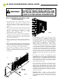
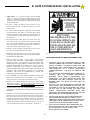
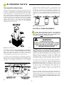
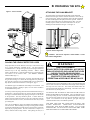
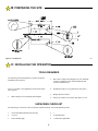
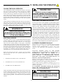
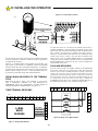
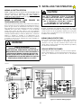
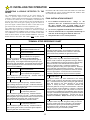
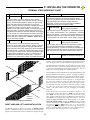
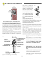
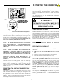
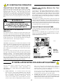
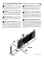
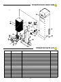
INSTALLATION AND
OWNER’S MANUAL
Class I Vehicular Slide Gate Operator
Model RS1000
Serial #:
103690
READ THIS MANUAL
Date Installed:
CAREFULLY BEFORE
Your Dealer:
New - Allstar’s
CGA2K™
TECHNOLOGY!
Meets all March 1, 2000
UL325 requirements.
INSTALLATION OR USE
SAVE THESE INSTRUCTIONS
As of date of manufacture, meets
all ANSI/UL 325 Safety
Requirements for Vehicular
gate operators
1
TABLE OF CONTENTS
Pre-Installation Notes ........................................ 3
Operator Class Information............................... 3
Section A: Gate System Design/Installation ... 4
Section B: Preparing the Site ........................... 6
The Concrete Operator Pad ......................... 6
Electrical Power Requirements ................... 6
Attaching the Chain Bracket ....................... 7
Placing Vehicle Detector Loops .................. 7
Section C: Installing the Operator ................... 9
Placing the Tower Operator ........................ 9
Electrical Hookup ......................................... 9
Accessory Equipment Hookup ................... 9
Wiring Radio Receivers ............................. 10
Wiring a 3 Button Station .......................... 10
Wiring Vehicle Detectors ........................... 11
Wiring Keypad or Telephone Entry ........... 11
Wiring Diagram .......................................... 11
Final Installation Checklist ........................ 12
Terminal Strip Reference Chart12
Section D: Starting the Operator ...........................13
Left/Right Hand Installations ............................13
Synchronous Operation (Master/Slave) ...........14
Mounting the Limit Cams ..................................14
Presetting the Sensitivity Adjustment ..............15
Timer To Close Adjustment ..............................15
Pre-Power On Checklist ....................................15
Final Settings .....................................................16
Maximum Run Timer..........................................16
Section E: Installation Notes for Auxiliary
Equipment ..........................................................16
Section F: End User Instructions ..........................17
Operational Guide for the End User .................17
Safety Guide for the End User ..........................17
Operator Exploded View & Parts List .....................19
Technical Specifications .........................................20
Warranty ...................................................................20
W A R N I N G H I G H V O LTA G E
ONLY A QUALIFIED TECHNICIAN SHOULD SERVICE THIS GATE OPERATOR
PERIODICALLY TEST SENSITIVITY OF OVERLOAD
*** READ MANUAL ***
DATE TESTED
LOG DATE OVERLOAD TEST
DATE TESTED
DATE TESTED
DATE TESTED
DATES OPERATOR
SERVICED
Figure 1
READ THESE STATEMENTS CAREFULLY AND FOLLOW THE
INSTRUCTIONS CLOSELY.
The Warning and Caution boxes throughout this manual are there to protect you and
your equipment. Pay close attention to these boxes as you follow the manual.
WARNING
CAUTION
WARNING
CAUTION
Indicates a MECHANICAL
hazard of INJURY OR
DEATH. Gives instructions
to avoid the hazard.
Indicates a MECHANICAL hazard
of DAMAGE to your gate, gate
operator, or equipment. Gives
instructions to avoid the hazard.
Indicates an ELECTRICAL
hazard of INJURY OR
DEATH. Gives instructions
to avoid the hazard.
Indicates an ELECTRICAL hazard
of DAMAGE to your gate, gate
operator, or equipment. Gives
instructions to avoid the hazard.
2
PRE INSTALLATION NOTES
The RS1000’s built-in overload detector will activate if there is
an increase in force above that normally required to move the
gate. The sensitivity is independently adjustable for the OPEN
or CLOSE direction. THE SENSITIVITY ACTIVATION
POINTS ARE ADJUSTABLE SETTINGS THAT MUST
BE DETERMINED AT THE TIME OF INSTALLATION.
THE SETTINGS MUST BE TESTED PERIODICALLY
TO INSURE PROPER OPERATION.
THE MORE
FREELY THE GATE WILL MOVE THE MORE
RESPONSIVE THE SETTINGS CAN BE MADE.
DILIGENT MAINTENANCE OF THE GATE ROLLERS
AND THE GATE TRACK WILL ASSURE THE MOST
RESPONSIVE OPERATION OF THE SENSITIVITY
MECHANISM. (See Pagez15).
The Allstar Tower Plus (Model RS1000) Vehicular Gate
Operator will provide convenience and assurance to the ultimate
users for many years. It is ruggedly built of the finest materials
and has been thoroughly inspected and tested at the Allstar
factory. It has many features that will aid in the installation and
testing of the complete gate system. The RS1000 has been
evaluated by Underwriters Laboratory, Inc. (UL) and is certified
to comply with ANSI/UL Standard for Safety 325, as evidenced
by the UL symbol on the name plate.
BEFORE ATTEMPTING INSTALLATION, READ
THIS MANUAL CAREFULLY SO YOU WILL BE
THOROUGHLY
FAMILIAR
WITH
THE
FEATURES OF THE TOWER PLUS AND ITS PROPER
INSTALLATION PROCEDURES.
THE IMPORTANT SAFEGUARDS
AND
INSTRUCTIONS IN THIS MANUAL CANNOT
COVER ALL POSSIBLE CONDITIONS AND
SITUATIONS WHICH MAY OCCUR DURING
ITS USE. IT MUST BE UNDERSTOOD THAT
COMMON SENSE AND CAUTION MUST BE
EXERCISED BY THE PERSON(S) INSTALLING,
MAINTAINING AND OPERATING THE EQUIPMENT
DESCRIBED HEREIN.
DO NOT USE THIS
EQUIPMENT FOR ANY OTHER THAN ITS INTENDED
PURPOSE — OPERATING A SLIDE GATE.
The RS1000 Vehicular Gate Operator is designated a Class I
Vehicular Horizontal Slide Gate Operator, and is intended for
usage in a residential home, maximum of four single families in
the dwelling, or a garage or parking area associated with such a
home, or a similar location with regard to the cycle usage (see
below). Vehicular Gate operators are also designated Class II
(high cycle usage commercial location or multi-family home),
III (industrial location not intended to service the general public,
i.e. factories), and IV (secure or restricted access locations, i.e.
airports and prisons). The RS1000 model operator cycle usage
is rated at a maximum of 10 cycles per hour, 50 cycles
maximum per day.
The RS1000 (as well as gate operators sold by other
manufactures) is designed to start and move vehicular slide
gates weighing as much as 300 pounds with a maximum of 16
feet in length. As such, the RS1000 is capable of producing
high levels of force. It is important in the design of the total
gate system that designers, installers and users be aware of the
hazards that may be associated with the IMPROPER design,
installation and use of vehicular gate systems and gate operators.
The gate operator is only one part of a complete automatic gate
operating system. As each location and usage is different, a
properly designed system will include all applicable safety
devices.
As the designer and installer of the GATE SYSTEM, you
must advise the purchaser on the proper use of the gate system.
You also have the primary responsibility of insuring that ALL
possible operational hazards have been considered and
eliminated. YOU MUST ADVISE AND WARN the purchaser
and the ultimate user of ANY HAZARDS that you have not
been able to eliminate.
The RS1000 has several features that can help reduce the
hazards of your gate system.
The Allstar RS1000 has a built-in "Overload Detector" that can
help reduce the hazards of your gate system. This mechanism,
however, must not be considered as the primary obstruction
sensing system. Consider all available options (electric leading
edges, photoelectric sensors, protective screen mesh, etc.) to
eliminate hazards in your gate system design.
ADVISE THE PURCHASER TO CHECK THE SENSITIVITY
OF THE OVERLOAD PERIODICALLY AND RECORD THE
DATE TESTED ON THE LOG PROVIDED ON PAGE 2. (See
Figure 1).
Connections for External Entrapment Prevention Sensors
Because all gate system installations are different, the RS1000
control panel provides independent connections for Open and
Close non-contact (photoelectric) and contact (edge) sensors. In
this way a photoelectric sensor could be utilized to guard the
gate area when closing and an edge sensor would provide the
protection when opening.
Depending on the particular
application a combination contact and non-contact sensor
protection system for the open and close directions may provide
more effective entrapment protection than a single device for
both directions. See pages 4, 5, 10, 11, 12, and 13.
SMART™ Self adjusting MAximum Run Timer (Patent
Pending)
The RS1000 has a Self adjusting MAximum Run Timer,
SMART™ (patent pending). The amount of time for the first
few cycles of operation are registered and averaged within the
motor controller circuitry. After the first few initial cycles, if
the gate is activated and no other command is given or an end
limit (open or close) is not reached in the previously counted
cycle time plus approximately 2 seconds, the operator will be
turned off. See page 16.
OTHER FEATURES
Auto Close Timer: Adjustable from 2 to 60 seconds, provides
an automatic closure of the gate from the full open position. See
page 15 and 16.
3
A: GATE SYSTEM DESIGN / INSTALLATION
WARNING!
TO REDUCE THE RISK OF SEVERE
INJURY OR DEATH: READ AND FOLLOW
ALL INSTALLATION INSTRUCTIONS AND
GATE SYSTEM DESIGN PARAMETERS!
104949
GATE SYSTEM DESIGN AND INSTALLATION
SAFETY CHECK LIST:
• The RS1000 operator may be installed only on a Class I
Vehicular Slide Gate. See page 3 for an explanation of the
different Class locations. See the last page of this manual for
the operator specifications (voltage, maximum gate weight &
length etc.).
• Make sure that the gate moves freely, all rollers are in good
working order, the gate does not bind in any manner and the
gate area is clean and free of irregularities. DO NOT
INSTALL THE OPERATOR UNTIL ALL GATE
PROBLEMS HAVE BEEN CORRECTED.
Figure 2
• Do not increase the built-in overload detector adjustment to
compensate for a poorly working gate. A well maintained gate
will ensure easy manual operation (if needed) and maximum
operator obstruction sensitivity.
• For ORNAMENTAL “GRILL TYPE” GATES (or any other
type of open gate where a handhold or toehold may be
achieved), injuries may occur when people put arms through
the openings or children “ride” the gate by standing on the
bars and holding on to the gate. THIS POTENTIAL
HAZARD CAN BE MINIMIZED BY INSTALLING A
MESH SCREEN ON THE GATE.
Allstar strongly
recommends the entire gate and adjacent fence area the gate
covers when open be meshed or guarded such that a handhold
or toehold cannot be achieved. At a minimum all openings on
a horizontal slide gate must be guarded or screened from the
bottom of the gate to a mimimum of 4 feet above the ground
to prevent a 2-1/4 inch (57.15 mm) sphere from passing
through the openings anywhere in the gate, and in that portion
of the fence the gate covers when in the open position. See
Figure 2.
• Install the operator on the inside of the property/fence line.
DO NOT install an operator on the public side of the fence line
or gate.
• Make sure the gate operating system is placed far enough back
from the road to eliminate traffic backup. The distance from
the road, size of the gate, usage level and gate cycle/speed must
be taken into consideration to eliminate potential hazards.
• The gate must be installed in a location so that enough
clearance is supplied between the gate and any adjacent
structures when opening and closing to reduce the risk
of entrapment.
• All Allstar gate operators are VEHICULAR GATE
OPERATORS and as such are NOT RECOMMENDED FOR
PEDESTRIAN traffic. In installations where pedestrians are
likely to be nearby, install a pedestrian gate and use leading
edge detectors and/or photocells in your design to protect
system entrapment zones. Allstar can provide these products
for incorporation in your design.
106709
• Use the illustration at left (Figure 3) to minimize the risk of
injury in your design of the slide gate operator system.
IDENTIFY THE ENTRAPMENT ZONES AND PINCH
POINT AREAS IN YOUR GATE.
Design the gate
installation to minimize the risk of entrapment in these areas.
Install additional safety equipment such as four wire edges and
photocells to further minimize risk. All entrapment zones are
required to be protected.
• Entrapment Zones:
Design in personal entrapment
protection devices to protect people from entrapment in the
zones shown in Figure 3 at left. Install vertical posts with gate
edges attached on both sides of the gate to prevent body
entrapment.
Figure 3
4
A: GATE SYSTEM DESIGN / INSTALLATION
• Pinch Points:
Use protective measures (guards, padded
edges, etc.) to protect people from the pinch points shown in
Figure 3. Attach roller guards in cantilevered gate systems
to minimize the risk of hands being caught between the top of
the gate and the roller.
MOVING GATE
CAN CAUSE
SERIOUS
INJURY OR
DEATH
• DO NOT consider the built-in overload detector as the
primary defense system.
system design.
Consider all options in the gate
• DO NOT connect any auxiliary equipment to the RS1000
operator (detectors, card readers, etc.) until the gate operator
and all its functions are fully tested. Only connect one device
at a time and ensure its proper function(s) before moving on to
the next device.
KEEP CLEAR !
Gate May Move at Any Time.
Do not allow children to play
in gate area or operate gate.
Operate gate only when gate
area is in sight and free of
people and obstructions.
• DO NOT locate any control device (key switch, switch, key
pad, card reader, etc.) in a position where it may be activated
by a person reaching through the gate or while touching the
gate in any manner. Locate all control devices a minimum of
10 feet from the gate when opened or closed.
• Outdoor or easily accessible controls must be of the security
type to prevent unauthorized use of the system.
• Install all devices that will open or close the gate in such a
104880
manner that THE GATE WILL BE IN FULL VIEW WHEN
THE DEVICE IS OPERATED.
Figure 4
AS THE INSTALLER YOU ARE RESPONSIBLE FOR:
• Before activating the "timer to close" option of the RS1000,
ENSURE THE PERSONAL ENTRAPMENT PROTECTION
DEVICES (operator reversing feature, edges, photocells) ARE
OPERATING and install VEHICLE DETECTOR LOOPS AND
VEHICLE DETECTORS for protection of user vehicles. Read the
manual for information on the installation of these devices. IF
VEHICLE DETECTOR LOOPS HAVE BEEN INSTALLED TO
PREVENT THE GATE FROM CLOSING ON A VEHICLE,
INSTRUCT THE USER TO PERIODICALLY CHECK THE
OPERATION OF THE DETECTORS.
1
2
• USE EXTREME CAUTION WHEN WORKING NEAR THE
BELTS AND PULLEYS when the operator cover is removed.
Apply power to the operator only when instructed to do so.
• When the cover of the RS1000 Control Box cover is removed, high
voltage will be exposed. NEVER LEAVE THE INSTALLATION
WITH THE CONTROL BOX COVER REMOVED.
3
• ALWAYS TURN OFF THE POWER BEFORE ATTEMPTING
SERVICE OF EITHER THE ELECTRICAL OR MECHANICAL
SYSTEMS.
• SECURELY ATTACH THE WARNING SIGNS provided with the
RS1000 on the gate (one on the outside and one on the inside) where
they can be seen by persons in the area of the gate to alert them of
automatic gate operation. Full compliance with the UL requirements
requires the signs be installed. (If the user refuses to have the
warning signs installed, Allstar recommends that you note this on
your records and have the user sign a disclaimer.) See Figure 4.
5
ASSURING THAT THE OWNER/END USER OF THE
SYSTEM UNDERSTANDS ITS BASIC OPERATION AND
SAFETY FEATURES. IN PARTICULAR, BE SURE THE
OWNER/END USER UNDERSTANDS THE LOCATION
AND OPERATION OF A MANUAL DISCONNECT
(WHERE PROVIDED)
OR HOW TO OPERATE THE
GATE .
YOU ALSO HAVE THE PRIMARY RESPONSIBILITY OF
INSURING THAT ALL POSSIBLE OPERATIONAL
HAZARDS HAVE BEEN CONSIDERED AND
ELIMINATED. YOU MUST ADVISE AND WARN THE
PURCHASER AND THE ULTIMATE USER OF ANY
HAZARDS THAT YOU HAVE NOT BEEN ABLE TO
ELIMINATE.
POINTING OUT TO THE OWNER/END USER OF THE
GATE SYSTEM THAT CHILDREN OR PETS ARE NOT
ALLOWED TO PLAY ON OR NEAR THE GATE, FENCE
OR ANY PART OF THE SYSTEM, AND THAT THE
SAFETY INSTRUCTIONS SUPPLIED WITH THIS
OPERATOR AND THEIR IMPLEMENTATION ARE THE
RESPONSIBILITY OF THE OWNER/END USER.
4
LEAVING THE INSTALLATION AND MAINTENANCE
MANUAL FOR THIS OPERATOR AS WELL AS ANY
ADDITIONAL SAFETY INFORMATION SUPPLIED WITH
THIS OPERATOR OR OTHER COMPONENTS OF THE
GATE SYSTEM WITH THE OWNER/END USER.
5
NOT PLACING IN SERVICE THIS OPERATOR IF YOU
HAVE ANY QUESTIONS ABOUT THE SAFETY OF THE
GATE OPERATING SYSTEM. CONSULT THE
OPERATOR MANUFACTURER.
B: PREPARING THE SITE
should be used for mounting the operator. The bolt pattern for the
RS1000 is 11-1/2” wide x 4-1/8” deep on center (See Figure 6). The
two rear bolts, (closest to the gate), should be no closer than 4-1/2"
from the near side of the gate to allow sufficient clearance for the
operator's cover. The rear bolts should also be no farther than 5-1/2"
from the gate if the chain brackets provided with the operator are to be
used.
THE CONCRETE OPERATOR PAD
Installation requires the presence of a suitable concrete pad as a base for
the operator. The dimensions of this pad should be sufficient to allow
at least 5" of clearance from each edge of the pad to the nearest
operator mounting hole. The top of the pad should be 3" above grade to
raise the operator above any standing water, while the depth of the pad
below grade is dependent on the weight and size of the gate and the soil
conditions at the site of the installation, also consult your local building
codes. The RS1000 cover is 34" high and is removed by lifting it
vertically off the operator. THE SITE FOR THE OPERATOR
SHOULD BE CHOSEN WITH AT LEAST 35" OF CLEARANCE
ABOVE THE TOP OF THE UNIT.
104883
Figure 6a: Parallel Placement
ELECTRICAL POWER REQUIREMENTS
NOTE: Before connecting the operator, use a voltmeter to
insure that the electrical service is 115 VAC. Connection to 220
VAC service is the most common cause of board failure in new
installations and is NOT covered by the warranty.
WARNING!
AVOID ELECTROCUTION:
DO NOT ROUTE LOW VOLTAGE WIRES IN SAME
CONDUIT AS HIGH VOLTAGE WIRES. FOLLOW
ALL LOCAL ELECTRICAL CODES OR THE
NATIONAL ELECTRICAL CODE.
Figure 5: Pad Configuration
103693
The RS1000 requires a 3-wire (Hot, Common, Ground), 115 VAC,
electrical circuit with a 15 Amp breaker for proper operation. In
installations with more than one operator, each operator must have a
separate service from the breaker panel. Powering multiple operators
from the same service can result in having to "de-sensitize" the
obstruction sensing adjustment to prevent one operator from
overloading the other. The electrical hookup is made in the junction
box located in the right front corner of the frame. See Figure 7, Page 7.
If no suitable concrete base exists, a pad must be poured. See Figures 5
and 6 for plans for this pad. Consult local building codes for depth of
base. Typical depths range from 24 to 36 inches. In either case, if
vehicles are going to be operated in the vicinity of the operator,
consider installation of protection posts in front of the operator.
If a suitable concrete base already exists for mounting the operator it
will be necessary only to drill mounting holes for the RS1000. 3/4"
mounting slots are located on each flange of the operator mounting
angle pieces. Four “redhead” anchor bolts, 3/8" or 1/2" in diameter,
The AWG wire size for the electrical service depends on the distance of
the operator from the breaker panel. Refer to the table below to
determine the correct wire size. The NOMINAL column is the ideal
distance from the breaker panel to the operator for a given wire size.
The distances shown in the MAXIMUM column should never be
exceeded. For distances greater than 3200', it is recommended that
your local utility be contacted to install a service feeder for the
installation.
Wiring from external controls such as guard shack, telephone entry,
keypad or card reader systems should be brought to the operator by a
conduit separate from the 115 VAC electrical hookup. Low voltage
control wires MUST NEVER be routed in the same conduit as A.C.
power wires. ALWAYS CONSULT AND FOLLOW ALL LOCAL
ELECTRICAL CODES.
103694
Figure 6: Operator Footprint
6
B: PREPARING THE SITE
Figure 7: Service Conduits
ATTACHING
THE CHAIN
BRACKETMAXIMUM
WIRE SIZE
NOMINAL
DISTANCE
DISTANCE
The chain brackets provided with the RS1000 operator should be
#14
100’
mounted on the the gate with the centerline of the slot200’
8" above the top
of the operator
end of the chain to the300’
gate and thread
#12 pad. Attach one150’
the other end
through
the
idler
pulleys
and
drive
sprocket.
#10
250’
500’ Attach the
free end to the bracket on the gate and tension the chain. You will
#8 a welder, or an400’
800’
normally require
electric drill with a 3/8"
bit, for
#6
600’
1200’
attaching the chain brackets to the gate. See Figure 8.
#4
1000’
2000’
103696
#2
1600’
3200’
103694
Figure 8: Chain Configuration
NOTICE: The Tower Operator cannot utilize a back
drive chain configuration.
PLACING THE VEHICLE DETECTOR LOOPS
WARNING!
Proper placement of vehicle detector wire loops is critical if the loops
are to provide satisfactory, extended service. The most important
considerations are: 1) Proper wire type and, 2) Good, tight connections
from the loop to the loop terminating connector. When a "Stand
Alone" vehicle detector is used, the detection loop is connected to the
wire harness on the detector itself. (See WIRING VEHICLE
DETECTORS, Page 11.)
RISK OF ENTRAPMENT
VEHICLE DETECTOR LOOPS WILL NOT DETECT
SMALLER VEHICLES SUCH AS MOTORCYCLES
OR GOLF CARTS, OR BICYCLES OR
PEDESTRIANS. PHOTOELECTRIC DETECTORS,
EDGE DETECTORS AND SEPARATE
PEDESTRIAN ACCESS MUST BE INSTALLED.
The RS1000 provides for the use of a “reversing” loop that will prevent
the gate from closing on a vehicle that has stopped in the path of the
gate. Note the "reversing” loop is normally made up of two independent
loop layouts connected to one detector. See Figure 9, page 8.
essential that the wires be held tightly in place by the foam backing and
that no voids exist that can collect water which might freeze and push
the loop wires out of the slot. The sealant used should match the
paving material and should not be hard setting. The lead in wires must
have at least six (6) twists per foot.
Two different types of installations will usually be encountered: 1) If
the driveway material is already in place, saw cuts will be needed to
accommodate the loop wires.
2) For loops where the paving material will be installed after the loop is
positioned, it is necessary that the loop wires be placed in Schedule 40
PVC pipe to maintain uniform loop spacing with respect to the surface
of the pavement. The loop should be placed 1.5 inches below the
surface of the pavement and at least 2" above any reinforcing steel The
lead in wires need not be in PVC, but must have at least six (6) twists
per running foot.
NO SPLICES ARE ALLOWED IN THE LOOP OR THE LEAD IN
WIRE TO THE FIRST JUNCTION BOX Above ground splices may
be used providing the wire is twisted, soldered and moisture sealed.
For best long term results, do not use wire nuts anywhere in the loop
system. For connections to the loop detector, gas tight crimp type
terminals should be used, and soldered if possible.
THE WIRE USED FOR THE LOOPS MUST BE HEAT AND
WATER RESISTANT. CROSS-LINK POLYETHYLENE
INSULATED, TYPE XLPE OR RHW IS BEST. U.S.E. IS ALSO
SATISFACTORY. DO NOT USE PVC INSULATED WIRE. WIRE
SIZE SHOULD BE #16 GA STRANDED OR LARGER.
For a saw-cut installation, observe the method recommended in Figure
9 for the corners. When installing a two-loop reversing system it is best
to bring the twisted lead wires from each loop to the operator so that the
loops may be properly phased. The saw cut must be to a depth of 1.5
inches, clean and with no sharp corners. After placing the wires, it is
7
B: PREPARING THE SITE
Figure 9: Loop Diagrams
104886
C: INSTALLING THE OPERATOR
TOOLS REQUIRED
The following tools and materials are required for proper
installation of the operator:
3.
Wire cutter, stripper and crimping tools. (For attaching
accessory equipment to the control/mechanical unit
enclosure terminal strip.)
Two 3/4" wrenches. (For tightening hex nuts on the chain
take-up bolts.)
4.
Standard screwdriver. (For junction box face plate.)
5.
Phillips head screwdriver.
6.
Electric arc welder or an electric drill with a 3/8" bit.
2.
Chain cutting tool. (For adjusting chain length.)
UNPACKING CHECKLIST
The following is a check list of the various parts included with the Tower Plus RS1000 operator:
1.
2.
3.
1 Tower Plus RS1000 Slide Gate Operator
w/Cover
2 Gate Warning Sign
8
4.
s
5.
2 Chain Brackets
6.
1 Chain Take-up Bolt Kit
C: INSTALLING THE OPERATOR
PLACING THE RS1000 OPERATOR
WARNING!
The recommended procedure for attaching the operator to the concrete
pad is first to locate and drill the hole for the right rear “redhead”
anchor bolt. Review Figure 6, Page 6. After placing the anchor bolt in
the hole, remove the cover and lower the operator over the bolt. Make
sure the two rear mounting holes on the operator are exactly the same
distance from the gate. (Improper alignment of the operator will cause
premature chain and idler sprocket failure.) With the operator properly
aligned with the gate, drill the remaining three holes with the operator
in place.
TO REDUCE THE RISK OF DAMAGE DUE TO
LIGHTNING, ENSURE A SOLID GROUND FROM THE
TOWER GROUND WIRE IN THE SERVICE ENTRANCE
2 x 4 HANDY BOX TO THE ELECTRICAL SERVICE
GROUND OR TO A EARTH GROUND STAKE NEAR
THE TOWER
ADDITIONAL LIGHTNING PROTECTION
Before inserting the remaining anchor bolts, make sure the operator is
sitting level. If any corners of the operator are resting above the pad,
slide flat washers under the operator and insert the anchor bolts through
the washers. Place the flat washers, lock washers and nuts on the
anchor bolts and tighten down the operator securely.
For those areas where a high probability of ground lightning strikes
exists (Florida, Georgia, etc.), additional lightning protection should be
installed in the RS1000. Although it may not be possible to protect
against all strikes, additional protection will substantially reduce the
occurrence of lightning damage. Allstar’s lightning data indicates that
the most strikes enter the RS1000 through the power lines. Effective
protection requires that the surge current from the lightning strike be
shunted to ground. This must be done without raising the potential of
the circuitry in the RS1000, with respect to ground, to the levels that
will damage the solid state circuitry. Lightning strikes generate
enormous currents for very short periods of time. Unfortunately, the
period of time is long enough to damage solid state components and
many times, other components. The key to success is a very low
resistance path from the surge protector to ground for these currents in
addition to a surge protector that will act fast enough to protect the solid
state circuitry. Several manufacturers offer suitable surge protectors.
WARNING!
RISK OF ELECTROCUTION
DO NOT BEGIN THE ELECTRICAL CONNECTION
PROCEDURES UNTIL THE POWER IS TURNED OFF
AT THE CIRCUIT BREAKER
ELECTRICAL HOOKUP
The operator requires a 3-wire, 115 VAC electrical hook-up for proper
operation. Ideally, the conduit containing the hook-up wires should exit
the concrete pad under the operator. There is a 2” x 2-3/4” gap on
either side of the operator pedestal for this purpose. Run flexible
conduit from the point where the conduit exists the pad and attach it to
the bottom of the junction box on the frame. Review Figure 7, page 7.
If the hook-up exits the pad external to the operator, drill a small hole in
the operator pedestal and use a conduit clamp to secure the conduit to
the pedestal. Cut a small slot in the skirt around the base of the cover.
This will allow the cover to fit down flush with the conduit in place.
ACCESSORY EQUIPMENT HOOK-UP
NOTE: Before continuing review the PRE-INSTALLATION
NOTES on page 3 and the GATE SYSTEM DESIGN/
INSTALLATION P ARAMETERS on pages 4 and 5 with
respect to the application and likelihood of pedestrian
traffic.
ALLSTAR
ADVISES
THAT
IF
THE
RS1000
VEHICULAR GATE OPERATOR IS INSTALLED IN A
RESIDENTIAL
AREA
OR
IF
THERE
IS
A
LIKELIHOOD OF PEDESTRIANS IN THE AREA YOU
MUST INSTALL A PHOTOELECTRIC DEVICE,
ELECTRIC GATE EDGE OR OTHER DEVICE TO
PROTECT AGAINST ENTRAPMENT!
Remove the junction box face plate. Using the wire nuts provided,
attach the three lead wires to the electrical hookup wires in the
following manner:
1.
The BLACK wire attaches to the 115 VAC HOT wire.
2.
The WHITE wire to the 115 VAC NEUTRAL wire.
3.
The GREEN wire to the GROUND wire.
Allstar can provide either a photoelectric device or an electric edge
depending on the application. Contact the factory and follow the
installation instructions and warnings provided with the device.
All low voltage accessory equipment is hooked-up to the 6 or 11
terminal strips located on the top of the control/mechanical unit
enclosure. See Figure 10.
NO ACCESSORY EQUIPMENT SHOULD BE INSTALLED
ABOVE THE POWER SWITCH HANDY BOX EXCEPT A
SINGLE CONTACT RADIO RECEIVER!
NOTE: The RS1000 control board comes equipped with a built-in surge
protection which MAY prevent damage to the controller board in the
event of a nearby lightning strike or a surge in the power lines. For the
surge protector to function, and as a general precaution, the operator
must be properly grounded. The third wire for the ground must be
installed .
WARNING!
IMPROPER WIRING COULD CAUSE
ELECTROCUTION OR DAMAGE TO CIRCUITRY.
FOLLOW LOCAL BUILDING AND ELECTRICAL
CODES.
9
C: INSTALLING THE OPERATOR
Figure 10: Terminal Strip Locations
110488
If a three wire receiver is to be used, the #1 terminal of the receiver is
normally COMMON to both the auxiliary transformer (power input)
and the radio relay. Most radio manufacturers label this terminal as 24
VAC. Connect a wire from the #1 terminal of the radio receiver to
terminal #1. The #2 terminal of the radio receiver is normally the relay
contact of the receiver. Connect a wire from this #2 terminal of the
radio receiver to the #2 terminal (RADIO RELAY) of the RS1000
control panel. The #3 terminal of the radio receiver is usually labeled
RADIO POWER and is connected to 24 VAC. Connect to terminal #3
of the RS1000 control panel.
If local electrical codes permit, use the operator's pedestal for mounting
accessory components. Otherwise, install the accessory equipment in
an appropriate electrical box.
There are 11 command inputs for the installer on the RS1000. The
inputs require a switch closure to COMMON of less than 100 OHMS
resistance and for more than 100 milliseconds duration. To familiarize
yourself with the input functions refer to Figure 10, Page 10 and see the
Reference Chart on Pages 12 and 13. A three push button station can
be wired in to provide full control of all command functions.
FOUR WIRE RECEIVERS
Four wire receivers replace the "spade" terminals on the RECEIVER
with 4 wires. These wires are typically color coded. The instructions
with the receiver must be carefully followed to properly connect the
receiver. For any 4 wire receiver, two of the wires will be for power
input and two will be for the relay contacts. Connect the two wires for
the power input to each side of the 24VAC RS1000 terminals #1 and
#3. Connect one of the two wires for the relay to terminal #1
(COMMON) and the other wire to terminal #2 (RADIO RELAY) on
the terminal strip. See Figure 11 for connecting 4 wire receivers.
WIRING RADIO RECEIVERS TO THE TERMINAL
STRIP
Radio Receivers may be either 3 wire (terminal) or 4 wire units.
THE 3 TERMINAL VERSION OF THE RECEIVER IS
PREFERRED SINCE NO ADDITIONAL CONNECTIONS TO
THE RECEIVER WILL BE REQUIRED. See Figure 10.
16 15 14 13 12 11 10 9 8 7 6
THREE TERMINAL RECEIVERS
110473
16 15 14 13 12 11 10 9 8 7 6
RED (PO W ER)
BLAC K (RELAY)
BLAC K (RELAY)
W HITE (POW ER)
CLOSE
5
4
3
2
1
STOP
0
4-W IRE
RADIO
RECEIVER
5
4
3
2
1
OPEN
110477
0
Figure 12: Wiring a Three Button Station
Figure 11: Wiring 4-Wire Receiver
10
C: INSTALLING THE OPERATOR
WIRING A 3-BUTTON STATION
CAUTION!
NOTE: THREE BUTTON STATIONS MAY BE ORDERED WITH
THE STOP BUTTON AS NORMALLY OPEN OR NORMALLY
CLOSED. THE RS1000 WILL OPERATE ONLY WITH A
NORMALLY OPEN STOP BUTTON. See Figure 12 for instructions
on wiring a three button station.
WIRING A KEYPAD, CARD
TELEPHONE ENTRY SYSTEM
READER
USE THE 6-TERMINAL STRIP TO POWER
A R ADIO RECEIVER O NLY . POW ERING
ANY OT HER ACCESSO RY DEVICE F ROM
T HE 6-T ERM IN AL ST RIP M AY RESULT
IN DAM AG E T O T HE POW ER
T R ANSF O RM ER IN T HE O PER AT O R.
OR
These devices activate the RS1000 by a relay contact closure within the
device. Typically, two wires or terminals are provided by the device to
operate the gate. Follow the manufacturers instructions on locating
these connections. If one of the connections at the device is labeled as
COMMON, then connect this to Terminal #1 or #0 of the RS1000
control panel. Connect the other contact to one of the following
terminals depending on function desired: Terminal #2 (ALTERNATE),
Terminal #4 (RADIO OPEN), Terminal #5 (FREE EXIT), Terminal #6
(OPEN) or Terminal #7 (CLOSE). If no identification of the
connections is noted at the device, then the two wires may be connected
to terminals #1 and one of the terminals above (again depending on
desired function) in any order.
Keypads, Card Readers and Telephone Entry Systems are typically
located remotely from the RS1000. The wiring used is low voltage
CLASS 2. Be sure to run an independent conduit for this wiring from
the entry device to the RS1000. The wire size should be #16 or #18
stranded for ease of handling.
WIRING VEHICLE DETECTORS
There are three connections that need to be made; 1) the AC power to
the detector, 2) the control connection to the RS1000, and 3) the
connection to the loop. All these connections will be made at the
vehicle detector connector. Follow the wiring instructions provided by
the vehicle detector manufacturer.
WARNING!
RISK OF ENTRAPMENT!
TO REDUCE THE RISK OF INJURY OR DEATH:
LOCATE KEYPAD, CARD READER, KEY SWITCH OR
SIMILAR ENTRY DEVICES IN A LOCATION WHERE A
USER CAN NOT REACH THROUGH THE GATE OR
FENCE TO ACTIVATE THE GATE OPERATOR. THE
RECOMMENDED DISTANCE BETWEEN THE GATE OR
FENCE AND ACCESSORY SWITCH IS 10 FEET.
VEHICLE DETECTOR POWER
Vehicle detectors may be ordered for 115 VAC or 24 VAC operation.
Allstar recommends that a 115 VAC Vehicle Detector be used. The 115
VAC may be obtained from the electrical service to the RS1000
operator .
110492 Rev. C
Figure 13: Schematic & Wiring Diagram
11
C: INSTALLING THE OPERATOR
CONNECTING A VEHICLE DETECTOR TO THE
RS1000
For a REVERSING LOOP connection of the vehicle detector, the
"relay" or "presence" output of the detector will be connected to
Terminal #11 (REV LOOP) of the RS1000 and the COMMON wire will
be connected to Terminal #0 or #16 (COMMON) of the RS1000. As
long as a relay closure is present on these two lines, the RS1000 will not
allow the gate to close. If the gate is opening, the gate will continue to
open. If the signal is removed before the Timer to Close times out, the
gate will close after the Timer to Close has completed its cycle.
For a FREE EXIT connection of a Vehicle Detector, the RELAY or
PRESENCE output signal will be connected to Terminal #5 (FREE
EXIT) and the RELAY COMMON signal connected to Terminal #0 or
#16 (COMMON) of the RS1000. DO NOT CONNECT THE FREE
EXIT OUTPUT SIGNAL TO ANY OTHER TERMINAL, SUCH AS
RADIO RELAY, BECAUSE THE GATE WILL CLOSE AFTER
REACHING THE OPEN LIMIT AND THE TIMER TO CLOSE HAS
COMPLETED ITS CYCLE, EVEN THOUGH THE VEHICLE HAS
NOT EXITED THE FREE EXIT LOOP.
FINAL INSTALLATION CHECKLIST
1.
Use a voltmeter to assure the service voltage to the
operator is 115 VAC. Connection to 220 VAC service is
the most common cause of board failure in new
installations and is NOT COVERED BY WARRANTY!
2.
No accessory equipment is installed in the control box.
3.
All wires attached to the 3 or 6 position terminal strip are
well clear of the moving parts under the unit cover.
4.
The junction box cover is securely fastened .
TERMINAL STRIP REFERENCE CHART
#
NAME
DESCRIPTION
#
NAME
DESCRIPTION
0
COMMON
8
STOP
Momentary or continuous signal.
1
24 VAC
2
ALTERNATE
Common connection for low voltage
signal inputs, terminals 2 thru 15.
Provides maximum 10 VA auxiliary
power for accessories.
Momentary input, must be released
and re-entered to be recognized.
Overrides all other signals. Once activated, the gate will
immediately stop and await a new command. If the STOP
input is continuously activated, the gate will not move.
9
This input is used for “COMMAND OPEN/COMMAND
CLOSE” applications. The 1st signal will cause the gate to
begin opening. A 2nd signal received during the open cycle
will stop the gate immediately. A 3rd signal will close the gate.
Connect appropriate access control devices to this terminal
and #0 or #16 COMMON.
3
24 VAC
4
RADIO OPEN
FREE EXIT
Provides maximum 10 VA auxiliary
power for accessories.
Momentary input, must be released
and re-entered to be recognized.
10
OPEN
Momentary or continuous signal. On/
Off mode set by Switch #1
Once activated the gate will open fully. Activation while the
gate is closing will cause it to re-open. Continuous activation
while the gate is open will prevent the Timer-To-Close function
from automatically closing the gate. Continuous signal
required to move the gate when in the alarm mode.
7
CLOSE
CLOSE PHOTO
Momentary or continuous signal.
This input is active only when referenced to the closing
direction, it has no effect on the gate when opening or about to
open. If activated when the gate is closing the gate will stop,
pause and reverse in the open direction for 1/2 second
(approx. 2 inches) and stop. Continuous activation will
prevent the gate from moving in the close direction. When the
input is removed normal operation is resumed. Continuous
activation while the gate is open will prevent the Timer-ToClose function (if enabled) from automatically closing the gate.
This input is intended for photoelectric eye systems and other
non-contact devices as appropriate. Connect here and to
terminal #16 COMMON. Multiple devices may be connected
Momentary or continuous input.
Once activated the gate will open fully. Activation while the
gate is closing will cause it to re-open. Continuous activation
while the gate is open will prevent the Timer-To-Close function
from automatically closing the gate.
6
Momentary or continuous signal.
This input is active only when referenced to the opening
direction, it has no effect on the gate when closing or about to
close. If activated when the gate is opening the gate will stop,
pause and reverse in the close direction for 1/2 second
(approx. 2 inches) and stop. Continuous activation will
prevent the gate from moving in the open direction. When the
input is removed normal operation is resumed. This input is
intended for photoelectric eye systems and other non-contact
devices as appropriate. Connect here and to terminal #16
COMMON. Multiple devices may be connected in parallel.
Once activated the gate will open fully. Activation while the
gate is closing will cause it to re-open.
5
OPEN PHOTO
11
REV LOOP
Momentary or continuous signal.
This input is active only when the gate is closing or when it’s
fully open and the Close Timer is operative. All stand-alone
vehicle detectors, photo-eyes and active edges should be
connected here and to terminals #3 or #13 COMMON.
Multiple devices may be connected in parallel.
Momentary or continuous signal. On/
Off mode set by Switch #1
Once activated the gate will close fully. Activation while the
gate is opening has no effect. Continuous signal required to
move the gate when in the alarm mode.
12
C: INSTALLING THE OPERATOR
TERMINAL STRIP REFERENCE CHART
#
DESCRIPTION
NAME
12 OPEN EDGE
#
Momentary or continuous signal.
This input is active only when referenced to the opening
direction, it has no effect on the gate when closing or about to
close. If activated when the gate is opening the gate will stop,
pause and reverse in the close direction for 1/2 second
(approx. 2 inches) and stop. Continuous activation will prevent
the gate from moving in the open direction. If a second
activation occurs before the limit switch is activated the gate will
stop and a require a renewed, intended input to move in the
open direction and before an automatic activation device (timer,
etc.) will operate. This input is intended for Electric Gate Edge
systems and other minimum-contact devices as appropriate.
Connect here and to terminal #16 COMMON. Multiple devices
may be connected in parallel.
13 CLOSE EDGE
DESCRIPTION
stop and a require a renewed, intended input to move in the
close direction and before an automatic activation device
(timer, etc.) will operate. This input is intended for Electric Gate
Edge systems and other minimum-contact devices as
appropriate. Connect here and to terminal #16 COMMON.
Multiple devices may be connected in parallel.
14 MASTER OPEN
Momentary or continuous signal.
Master (output configuration)
This terminal is used to coordinate two independent systems
(two control box/mechanical unit combinations controlling
separate gate leaves). Connects to terminal #6 (OPEN) in the
companion control box and controls the direction of movement
in the companion box (See Switch Jumper Position, Page 16
15 MASTER CLOSE Momentary or continuous signal.
Master (output configuration)
Momentary or continuous signal.
This input is active only when referenced to the closing
direction, it has no effect on the gate when opening or about to
open. If activated when the gate is closing the gate will stop,
pause and reverse in the open direction for 1/2 second (approx.
2 inches) and stop. Continuous activation will prevent the gate
from moving in the close direction. Continuous activation while
the gate is open will prevent the Timer-To-Close function (if
enabled) from automatically closing the gate. If a second
activation occurs before the limit switch is activated the gate will
This terminal is used to coordinate two independent systems
(two control box/mechanical unit combinations controlling
separate gate leaves). Connects to terminal #7 (CLOSE) in the
companion control box and controls the direction of movement
in the companion box (See Switch Jumper Position, Page 16
16 COMMON
Common connection for low voltage
signal inputs, terminals 2 through 15.
opening - both as you look at the installation from the inside (secured
side). See Figure 14 for a pictorial example of a right hand operation.
107033
Left hand operation is described as the gate sliding to the left to open
and where the operator is mounted to the left of the gate opening - both
as you look at the installation from the inside (secured side). Also see
Figure 14 for a pictorial example of a left hand operation.
Right Hand
Installation
Outside
NAME
Note the different wiring configurations for right-hand installations and
left-hand installations (see Figures 15 and 16). To change to a different
handed operation the capacitor wires and limit wires must be changed.
For proper operation, the capacitor and limits must be wired as shown.
Inside
Locate the limit switches as shown in Figure 16. As shipped from
the factory the switches are wired for right hand operation (red/
green on the lower switch and yellow/green on the upper switch).
To reconfigure the limit switches for left hand operation reroute
the yellow wire to the lower switch and the red wire to the upper
switch. The limit switches are now configured for left-hand
operation.
Outside
Inside
Locate the capacitor wire connections as shown in Figure 15. On
one capacitor terminal post there is a RED wire from the motor
and a RED wire from the high voltage wire harness and on the
other capacitor terminal post there is a BLUE wire from the motor
and a BLUE wire from the high voltage wire harness. Trace and
identify the RED and BLUE wires which originate at the motor.
SWITCH THESE WIRES such that the RED motor wire is on the
capacitor terminal post with the BLUE wire from the high voltage
wire harness AND the BLUE motor wire is on the capacitor
terminal post with the RED wire from the high voltage wire
harness. The high voltage wire harness is now configured for lefthand operation. Left-hand conversion is now complete.
Left Hand
Installation
Figure 14: Left Hand vs. Right Hand Installation
RIGHT HAND AND LEFT HAND INSTALLATION
The RS1000 operator is wired at the factory for RIGHT HAND
operation. Right hand operation is described as the gate sliding to the
right to open and where the operator is mounted to the right of the gate
13
D: STARTING THE OPERATOR
similar) protecting an entrapment zone
particular to the secondary unit could be
wired to that unit only and would react
individually to the detection of an
obstruction. Synchronous movement
would resume once the obstruction is
cleared and an open or close command
is received by the primary operator.
110502
SIDE VIEW
CAPACITOR HV WIRE
CAPACITOR
CONNECTIONS
To obtain synchronous operation (4
Steps):
1. Wire the Primary Operator Terminal
#14 to Terminal #6 in the Secondary
Operator.
2. Wire the Primary Operator Terminal
#15 to Terminal #7 in the Secondary
Figure 17: Mounting
Operator.
Limit Cams to Chain
3. Place the Master/Slave Jumper on the
Primary Operator motor control board to
the primary position. See Figure 19, Page 16.
4. Place the Master/Slave Jumper on the Secondary Operator motor
control board to the secondary position. See Figure 19, Page 16.
Figure 15: Left Hand Conversion — Harness & Wire Locations
MOUNTING THE LIMIT CAMS
SYNCHRONOUS OPERATION (MASTER/SLAVE)
Before turning on the main power, the limit cams must be mounted
to the chain in their approximate positions. See Figures 16 and 17.
Figure 16 illustrates a view of the RS1000 Control Box/
Mechanical Unit that faces the gate which depicts the Output Drive
Sprocket components.
Two RS1000 units in a bi-parting situation (one wired right-hand and
one wired left hand, see above) can be configured to operate in a
synchronous manner. The units can be wired together to operate as one
system, with one unit controlling the movement of both. Additionally,
the installer can customize the installation of the external entrapment
protection devices. These devices can be wired to the primary
(controlling) operator or alternately to the individual units as the
situation dictates or the end user requires.
Figure 17 shows how to install the Limit Cams to the chain.
NOTE: IT IS IMPORTANT TO INSTALL THE CAMS
AROUND THE WHOLE LINK AS ILLUSTRATED AND
WITH THE STUD/NUT IN THE PROPER ORIENTATION
AS OUTLINED IN THE FOLLOWING PARAGRAPHS.
When an external entrapment protection device is wired to the primary
unit (such as would be recommended for a photoeye across the entire
opening) both units will react to the detection of an obstruction,
regardless of the location of the obstruction. An edge device (or
Manually push the gate all the way open. As depicted in Figure 17
locate and mark with chalk the proper chain link (depending on
Right-Hand or Left-Hand operation) for OPEN Limit
operation.
110501A1
WHEN FULLY ______
MARK THIS CHAIN LINK:
OPENED (RIGHT-HAND)
CLOSED (LEFT-HAND)
LIMIT SWITCH WIRING
RED/GREEN-RIGHT HAND
YELLOW/GREEN-LEFT HAND
110501A2
LIMIT SWITCH WIRING
YELLOW/GREEN-RIGHT HAND
RED/GREEN-LEFT HAND
WHEN FULLY ______
MARK THIS CHAIN LINK:
CLOSED (RIGHT-HAND)
OPENED (LEFT-HAND)
ENSURE LIMIT SWITCH
ACTUATORS ARE SET
AS SHOWN TO ACCEPT
LIMIT CAMS.
Manually push the gate all the way closed. Following
the procedure shown in Figure 17, mount the Limit
Cam on the chain link that was marked with chalk in
the previous step, the link should now be parallel with
the ground and approximately 4 to 5 feet from the end
of the gate. The cam MUST BE mounted such that
the lobe is DOWN (TOWARD THE GROUND).
NOTE:
IF RIGHT-HAND OPERATION
(STANDARD) MOUNT THE CAM WITH THE
STUD/NUT POINTING AT THE GATE, IF LEFTHAND OPERATION MOUNT THE CAM WITH
THE STUD/NUT POINTING AWAY FROM THE
GATE.
As depicted in Figure 16 locate and mark with chalk
the proper chain link (depending on Right-Hand or
Left-Hand operation) for CLOSE Limit operation.
ENSURE LIMIT
CAMS LOBES
POINT DOWN
At this time recheck the Toggle Limit Switch
ACTUATORS for proper positioning to accept the
limit cams. See Figure 16.
Figure 16: Limit Cam Mounting & Limit Switch Wiring
14
D: STARTING THE OPERATOR
The RS1000 is shipped from the factory with the potentiometers at their
most sensitive setting. Turn the potentiometer 1/4 turn clockwise to
prevent the overload circuit from tripping due to the gate's inherent
friction.
(See FINAL SETTING OF THE OBSTRUCTION DETECTION
SENSITIVITY, Page 16.)
110503A1
WARNING!
LOCATION OF
OVERLOAD FORCE
ADJUSTMENTS
RISK OF ENTRAPMENT.
THE SENSITIVITY ADJUSTMENT MUST BE SET
MORE PRECISELY PRIOR TO COMPLETING THE
OPERATOR INSTALLATION
TIMER TO CLOSE SETTING
The Timer to Close is controlled by the setting of the “AUTO CLOSE
TIMER” potentiometer on the control board, see Figure 19. When the
pot is adjusted fully counter-clockwise the Timer-To-Close is disabled.
Turning the pot approximately 1/4 turn clockwise will enable the Timer
To Close function with a delay of approximately 2 seconds between the
gate reaching the full open position and automatically closing. To
increase the time delay continue to turn the pot in the clockwise
direction to a maximum delay of 60 seconds (one minute).
Figure 18: Location of OL Force Adjustments
Manually push the gate all the way open again. Following the
procedure shown in Figure 17, mount the Limit Cam on the chain
link that was marked with chalk in the previous step, the link
should now be parallel with the ground and approximately 4 to 5
feet from the end of the gate. The cam MUST BE mounted such
that the lobe is DOWN (TOWARD THE GROUND).
IT IS HIGHLY RECOMMENDED THAT AUXILIARY
ENTRAPMENT PROTECTION DEVICES BE INSTALLED
WHENEVER THE TIMER TO CLOSE OPTION IS ENABLED.
NOTE:
IF RIGHT-HAND OPERATION (STANDARD)
MOUNT THE CAM WITH THE STUD/NUT POINTING
AWAY FROM THE GATE, IF LEFT-HAND OPERATION
MOUNT THE CAM WITH THE STUD/NUT POINTING AT
THE GATE.
PRE POWER-ON CHECKLIST
The following checklist should be used before turning on power to
the operator:
NOTE: ENSURE THAT WHEN THE CAMS ENTER THE
LOWER IDLER SPROCKETS THEY ARE ORIENTED
PROPERLY AS FOLLOWS: WHEN THE CAM ROUNDS
THE INSIDE SPROCKET (CLOSEST TO THE PEDESTAL)
ITS STUD/NUT SHOULD BE POINTING TOWARDS THE
PEDESTAL, WHEN THE CAM ROUNDS THE OUTSIDE
SPROCKET (FARTHEST FROM THE PEDESTAL) ITS
STUD/NUT SHOULD BE POINTING AWAY FROM THE
PEDESTAL.
1.
2.
3.
4.
THE VOLTAGE TO POWER THE UNIT IS 115 VOLTS
AC;
The proper Left- or Right-hand Mode has been selected;
The Limit Cams have been mounted to the chain;
The Overload Sensitivity has been preset.
When the PRE POWER-ON CHECKLIST has been completed,
turn on the main power switch located in the 4 X 4 electrical box
under the control box/mechanical unit. Give the operator a push
button input command with a jumper wire attached to terminal #1
or #16, COMMON, on the terminal strip and touched briefly to
terminal #2, ALTERNATE to START the gate. If the gate was
fully open, as left in the previous step "MOUNTING THE LIMIT
CAMS" the gate will start in a close direction. If the gate was in
any other position but fully open, the gate will start in the open
direction.
The limit cams are now roughly adjusted. If the gate should stop
short of fully opened or closed, or if it bangs against the end stops
during operation, the limit cams can be fine-tuned after the
operator is powered up. (See FINAL SETTING OF THE LIMIT
CAMS, page 16.)
PRESETTING THE OBSTRUCTION DETECTION /
SENSITIVITY
Give the operator an ALTERNATE input command. The operator
should stop if OPENING; stop, pause and reverse if the gate were
moving in the CLOSE direction. See BASIC OPERATIONAL
GUIDE page 16.
The operator is equipped with an obstruction detection circuit which
will detect MOST obstructions in the gate's path. See Figure 18. The
sensitivity can be independently adjusted for OPEN and CLOSE with
the potentiometers on the controller board labeled, "OVERLOAD
FORCE". Turning a potentiometer clockwise decreases the sensitivity
and turning it counterclockwise increases the sensitivity.
15
D: STARTING THE OPERATOR
FINAL SETTING OF THE LIMIT CHAIN CAMS
SMART™ Self adjusting MAximum Run Timer
(Patent Pending)
If the gate stops short of being fully open or closed or if it bangs
against the end stops, turn off the main power and move the
appropriate limit chain cam. Each whole link on the chain
represents about 1" of gate travel. The cams should only have to
be moved one or two whole links in either direction to fine tune the
gate's limits of travel. When final adjustment has been completed,
insure that the cam nuts are properly tightened. Review Figurez16
& 17.
The RS1000 has a Self adjusting MAximum Run Timer, SMART™
(patent pending). The amount of time for the first few cycles of
operation are registered and averaged within the motor controller
circuitry. After the first few initial cycles, if the gate is activated and no
other command is given or an end limit (open or close) is not reached in
the previously counted cycle time plus approximately 2 seconds, the
operator will be turned off.
The RS1000 has a thermal cutoff switch to protect the motor and
capacitor from sustaining damage. If the gate has been operated for an
excessive number of consecutive cycles the thermal cutoff switch will
open and the power will be turned off to the motor and control circuitry.
After a cooling off period the thermal cutoff switch will automatically
reset and the gate can be operated once again.
WARNING!
RISK OF ELECTROCUTION
DO NOT BEGIN TO SET THE FOLLOWING
ADJUSTMENTS UNTIL THE POWER IS TURNED
OFF AT THE MAIN POWER SWITCH
FINAL SETTING OF THE CLOSE TIMER
To alter the amount of time that the Close Timer will hold the gate
open, adjust the timer potentiometer located on the control board. See
Figure 19 below.
FINAL SETTING OF THE OPERATOR
SENSITIVITY
The Close Timer is adjustable from 2 to approximately 60 seconds.
Turning the potentiometer clockwise increases the delay; turning it
counterclockwise decreases the delay.
The obstruction detection sensitivity was preset before turning on the
main power to prevent the operator from "self-tripping" during testing.
To set the OPEN sensitivity, start the gate in motion in the Open
direction and turn the overload potentiometer counterclockwise until
the gate stops and reverses. Then back the potentiometer off 10 degrees
in the clockwise direction. Review Figure 18, Page 15.
Repeat for the Close sensitivity.
110503A2
CAUTION: During this process the alarm will sound if the overload
sensor is activated two sequential times before the gate reaches a limit
(open or close). To reset the alarm sensor use constant pressure on a
control button connected to the OPEN or CLOSE input and move the
gate to a fully open or closed position or turn off and restore the power
to the operator.
Syncronous Operation
Switch
Edge of
Board
Restart the gate and give the leading edge a firm blow with the heal of
your palm. Don't stand directly in the gate's path while testing the
obstruction sensitivity. The obstruction detection should respond
immediately to the blow. The overload potentiometer must be adjusted
to the most sensitive setting possible without causing "self-tripping"
due to the gate's inherent friction or to variations in the track. Try
readjusting the potentiometer several times by small increments, testing
the gate in both directions of travel, until you are satisfied.
123
Figure 19:
Location of
Timer / Sync
Select Switch
Move Jumper to Pins
1 & 2 for Slave Mode
LOCATION OF AUTOCLOSE TIMER
ADJUSTMENT AND SYNCRONOUS
OPERATION SWITCH
E: INSTALLATION NOTES FOR AUXILIARY EQUIPMENT
You are now ready to install and connect the auxiliary
equipment.
INSTALLATION STEPS DETAILED IN
SECTIONS A, B, C AND D MUST BE COMPLETE BEFORE
PROCEEDING.
lamp on the front panel of the detector and a metal plate
over the loop. When you are satisfied that the detector is
working properly, connect the output wires to terminals 4
and 5 on the control panel of the RS1000.
1.
Give the gate an open command and allow the close timer
to start the gate to close. Place the metal plate over the
loop and observe that the gate stops and reopens.
Vehicle Detectors:
If a Vehicle Detector (Reversing
Loop) is to be a part of this installation, start with this
first. Connect the vehicle detector to AC power and the
loop in accordance with the manufacturer's instructions
and the information contained in this manual. Do not
connect to the terminal strip of the RS1000 at this time.
Test the vehicle detector independently using the presence
2.
16
Installing other entry devices: After you are satisfied that all the
loops are functioning properly, proceed with the installation of the
additional devices, such as a radio receiver or deluxe wall station.
Connect the radio receiver as described on page 10.
F: END USER INSTRUCTIONS GATE OPENER OPERATION AND SAFETY GUIDE
WARNING!
IMPORTANT SAFETY INSTRUCTIONS. TO REDUCE THE RISK OF SEVERE INJURY OR
DEATH: READ AND FOLLOW ALL INSTRUCTIONS IN THIS MANUAL!
sides of your gate. Keep them clean and legible.
To the Owner/End User of Allstar’s Gate Operator:
Read and follow the safety points on this and the following page which
present the basic guidelines for the safest operation of your gate
operator system.
Thank you for choosing an Allstar product. We are confident you will
have many years of use and satisfaction with your gate operator.
Our Gate Operator is part of your unique gate operating system, which
may consist of a variety of components, including the gate, the gate
tracks, posts, and electronic features. These components combined
present certain risks and safety issues of which you, the end user, must
be aware.
ALL APPROPRIATE SAFETY FEATURES MUST BE
INCORPORATED INTO YOUR GATE SYSTEM.
SAVE THESE INSTRUCTIONS !
Each unique system presents a unique set of hazards which we cannot
possibly address individually. These instructions will help you to
identify the potential risks and safety issues your gate operator system
presents, and guide you as you make your system as safe as possible for
everyone who uses it.
BASIC OPERATIONAL GUIDE
•If the gate is fully closed an Open Button, Alternate, Radio or Free
Exit input will cause the gate to begin moving in the open direction.
•If the gate is fully open a Close Button, Alternate, or Radio input will
Your first step is to consider the intended use of the gate system, who
will be using the gate system, and in what manner the system is
installed. You should have a clear understanding of how often the gate
will be opened, who will be opening it, whether children and the
general public will be near the gate system, and how close the gate
system is to public property. Once you have answered these questions,
you are ready to decide what safety measures must be taken to prevent
injury.
cause the gate to begin moving in the close direction.
•If the gate is moving in a Close direction a Close Non-Contact Sensor
or a Close Contact Sensor input will cause the gate to stop, pause and
reverse for approximately 2 inches in the Open direction.
•If the gate is moving in a Close direction an Open Button, Radio,
Reversing, or Free Exit Loop input will cause the gate to stop, pause
and reverse and run in the Open direction.
•If the gate is moving in a Close direction a Stop Button or Alternate
input will cause the gate to stop. A subsequent Alternate input will
cause the gate to begin moving in the Open direction.
•If the gate is moving in an Open direction an Open Non-Contact
Sensor, Open Contact Sensor input or an Open Overload activation
will cause the gate to stop, pause and reverse for approximately 2
inches in the Open direction.
•If the gate is moving in an Open direction a Stop or Alternate input
will cause the gate to stop. A subsequent Alternate input will cause
the gate to begin moving in the Close direction.
MANUAL OPERATION - The gate can be moved open or
close in case of power failure or other need to move the gate manually
without disconnecting the operator chain. Remove power from the unit
(if not already off) and firmly grasp the leading edge of the gate. Push
or pull the gate in the direction desired. The amount of force required
to move the gate will depend on the gate weight and the inherent
friction of the overall system. Manual operation is to be attempted only
when the operator is not moving the gate under power.
To minimize the risk of entrapment in your gate system, install the
following safety features:
•
•
•
•
•
•
•
Electric gate edges
Enclosed tracks
Vertical guard posts
Protective screen mesh
Photoelectric sensors
Instructional and precautionary signs
Covers for exposed rollers
Each safety feature is a separate component in your gate system. Read
and follow all instructions for each of the components of your unique
system. Ensure that all instructions for mechanical components,
safety features and the Allstar Gate Operator are available for
everyone who will be using your gate system.
The two warning signs shipped with your Gate Operator (See Figure 4,
Page 5 of this manual) must be installed in prominent positions on both
PRECAUTIONS FOR
PEDESTRIAN TRAFFIC
OR RESIDENTIAL
AREAS
Figure 20: Entrapment Protection
The internal operator overload
sensor may not be adequate
entrapment protection in all
situations to prevent arm, leg, or hand
injuries. Padded electric gate edges, roller
guards, pneumatic gate edges, or
photoelectric sensors are therefore
necessary when automatic gates are used
near pedestrian traffic. See the figure
below. Use of pedestrian walk gate is
mandatory where there is nearby
pedestrian traffic.
107037
17
F: END USER INSTRUCTIONS GATE OPENER OPERATION AND SAFETY GUIDE
AVOID ENTRAPMENT: Stay away from the path of the gate
and all moving parts (gate leafs, etc.) at all times. Do not place
arms or legs through the gate. Keep clear of the pinch points
identified in Figure 21 below. Install guards or other safety features to
prevent access to pinch point areas. Install guards on open rollers. The
force of the gate can cause serious personal injury or death.
INSTALL SAFETY DEVICES: In residential applications or in
areas where pedestrians may be present, or if your gate closes
automatically, be sure an electric edge(s) and/or a photoelectric sensor(s)
has (have) been installed and is/are operating properly. These features are
intended to detect pedestrian traffic and prevent injury or entrapment.
Loop detectors may be installed to detect vehicular traffic and prevent
vehicular damage.
NEVER ALLOW A CHILD TO OPERATE GATE
CONTROLS. Do not allow anyone to “ride” a gate, or play in
the area of a gate. Install and store all controls out of children’s reach.
Do not stand near or on the gate. Gate may be activated without notice.
Install a pedestrian gate in applications where pedestrians need access.
This entrance is for vehicles only. Pedestrians must use a separate entrance.
MAINTAIN THE GATE AND GATE HARDWARE: A
damaged gate or one that cannot be easily opened and closed
manually must be repaired before installing a gate operator. A poorly
operating gate may cause the load sensing device of the operator to fail,
causing a risk of entrapment. Never over tighten the clutch or load sensing
device to compensate for a poorly operating slide gate. Correct all
mechanical problems on the gate and gate hardware before installing the
gate operator. Have a qaulified service technician make repairs to the gate
and gate hardware.
KEEP GATE IN SIGHT: Never activate the gate unless it is in
sight. Install mounted controls in full view of the gate. Be sure the
gate area is clear before activating the gate, and watch the gate and gate area
as the gate is in motion. NO ONE SHOULD CROSS THE PATH OF A
MOVING GATE.
MAINTAIN ALL COMPONENTS OF GATE SYSTEM:
Follow all maintenance instructions included with the gate, the
gate operator, and the safety features and/or accessories that make up your
gate gate operator system. Have a professional service technician perform
any adjustments or maintenance to the components. Fully test all safety
features monthly.
If faulty equipment is discovered or suspected,
discontinue the use of the gate operator SYSTEM immediately, and
have the equipment repaired or replaced. The gate must reverse on
contact with a rigid object or when an object activates the non-contact
sensor. After adjusting the force or limit of travel, retest the gate operator.
Failure to adjust and retest the gate operator properly can increase the risk of
injury or death.
LOCATE MANUAL CONTROLS SAFELY:
A manual
control such as a pushbutton or keyswitch must be included in
your gate system design to be used if automatic controls such as radio
controls or loop detectors do not function. Carefully consider the placement
of the manual control: It must be out of reach of the gate so that no one
pushing the button or inserting the card is in the path of the gate or moving
parts; it must also be within sight of the gate so that the operator can watch
the gate and gate area during operation. The recommended minimum
distance between the gate or fence and manual control accessory is 10
feet.
106709
Figure 21: Pinch Points
18
OPERATOR EXPLODED VIEW
110504
OPERATOR PARTS LIST
ITEM #
1
PART
#
110 506
DESCRIPTION
TOWER RS1000 HEAD UNIT, COMPLETE
1 EA
1A
110505
MOTOR CONTROL CIRCUIT BOARD COMPLETE
1 EA
2
103679
TOWER RS1000 PEDESTAL
1 EA
3
103581
POWER SWITCH BOX
1 EA
4
103648
COVER ASSEMBLY, 4 X 4 HANDY BOX, SWITCH
1 EA
5
100004
FRONT IDLER PULLEY
2 EA
6
010395
SHOULDER SCREW
1 EA
7
010071
WASHER, 9/16 X 1 3/8 X 1/8
1 EA
8
006043
KEPS NUT, HEX, 5/16-18
2 EA
9
006031
KEPS NUT, HEX, 3/8-16
1 EA
10
010064
WASHER, FLAT, 3/8
1 EA
12
021125
SCREW, 10-24 X 3/4
2 EA
13
103399
SCREW, 10-32 X 3/8
1 EA
14
010014
TINNERMAN NUT, U, 5/15-18
3 EA
15
006030
SCREW, HHCS, 5/16-18 X 1
3 EA
16
009090
WIRE NUTS
5 EA
17
103580
TOWER RS1000 COVER
1 EA
19
QTY
TECHNICAL SPECIFICATIONS
DRIVE
PHYSICAL
PRIMARY DRIVE SYSTEM: Belt and Pulley (3l290 V-Belt)
PAD: 22” W x 18”D x 3” Elevation
OVERHEAD CLEARANCE: Minimum 35” Required
TOTAL SPEED REDUCTION: 6.4:1
UNIT SIZE: 10-1/2”W x 10-1/2”D x 34” H
OUTPUT SHAFT: 5/8” Diameter
PEDESTAL FRAME: 11 GA. Steel, Phosphatized with
DRIVE MECHANISM: 6-Tooth Sprocket; #65 Roller Chain
COVER: Architecturally Designed, Rust Free
LIMITS: Independent Open & Close; Drive
Chain Mounted Limit Cams
SHIPPING WEIGHT: 65 lbs.
ELECTRICAL
PRIMARY VOLTAGE: 115 VAC, 60 Hz, Single Phase
CAPACITIES
MAX. GATE WEIGHT: 300 lbs., Level Grade
ELECTRICAL SOURCE: One 3-Wire, 15-Amp Service From
MAX. GATE WIDTH: 16 ft.
CONTROL VOLTAGE: 5 VDC
MAX. CYCLES PER HOUR: 10 Open/Close Per Hour; 50 Open/
RADIO RECEIVER POWER: 24 VAC, 20 mA
Close Per Day
MOTOR: 1/2 HP, 6.0 Amp, PSC, Instant
GATE SPEED: 8.2 inches/second
Specifications subject to change without notice. Consult the factory.
Manufacturer’s Limited Warranty
Allstar warrants its gate operators to be free from defect in material and workmanship for a period of five (5) years from the date of purchase
for single family home use and three (3) years from the date of purchase for multi-family and commercial use. This warranty covers all
components except the electronic circuit boards which are warranted for three (3) years from the date of purchase for single family home use
and two (2) years from the date of purchase for multi-family and commercial use. To obtain service contact your dealer.
To obtain service under this warranty the buyer must obtain authorization instructions for the return of any goods from Allstar before
returning the goods. The goods must be returned with complete identification, with copy of proof-of-purchase, freight prepaid and in
accordance with Allstar’s instructions or they will not be accepted. In no event will Allstar be responsible for goods returned without proper
authorization or identification.
Goods returned to Allstar for warranty repair within the warranty period, which upon receipt by Allstar are confirmed to be defective and
covered by this limited warranty, will be repaired or replaced at Allstar’s sole option, at no cost and returned pre-paid. Defective parts will
be repaired or replaced with new or factory rebuilt parts at Allstar’s sole option.
This limited warranty does not cover non-defect damage, damage caused by unreasonable use, damage caused by improper installation or
care, vandalism or lightning, fire or excessive heat, flood or other acts of God (including, but not limited to misuse, abuse or alterations,
failure to provide reasonable and necessary maintenance), labor charges for dismantling or reinstalling a repaired or replaced unit, or
replacement batteries.
These warranties are in lieu of all other warranties, either expressed or implied. All implied warranties of merchantability and/or fitness for a
particular purpose are hereby disclaimed and excluded. Under no circumstances shall Allstar be liable for consequential, incidental or
special damages arising in connection with the use or inability to use this product. In no event shall Allstar’s liability for breach of warranty,
breach of contract, negligence or strict liability exceed the cost of the product covered hereby. No person is authorized to assume for Allstar
any other liability in connection with the sale of this product.
This warranty gives you specific legal rights. You may also have other rights which vary from state to state. Warranty effective after
January 1, 2001.
c.p. Allstar Corporation
Downingtown, PA 19335
This Gate Operator is built in the USA and
complies with all requirements of ANSI/UL
Standard 325.
P/N 110500 Rev. C
November, 2001
20