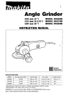
1
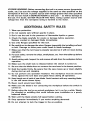
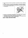
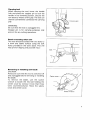
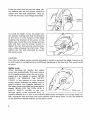
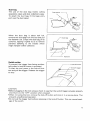
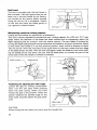
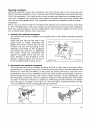
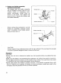
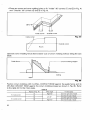
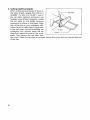
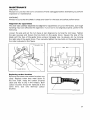
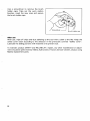
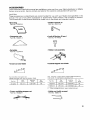
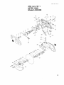
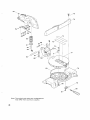
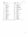
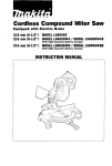
Miter Saw
255 mm (10”) MODEL LSl030N
Equipped with Electric Brake
INSTRUCTION MANUAL
DOUBLE
INSU1AT ION
r\O
U-
I
1
No load speed (RPM)
00
45O (left and right)
90.5 m m x 9 5 mm
(3-9/16" x 3-3/4")
90.5 mm x 6 7 mm
(3-9/16" x 2-5/8")
6 9 m m x 1 3 0 mm
(2-3/4" x 5-1/8")
I
6 9 m m x 92 mm
(2-3/4" x 3-5/8")
I
.............................................................................
4,600
5 3 0 mm x 4 7 6 m m x 5 3 2 m m
32" x 18-23/32" x 20-15/16")
....................................................
11.0 kg (24.2 Ibs)
Manufacturer reserves the right t o change specifications without notice.
Note: Specifications may differ from country t o country.
WARNING: For your personal safety, READ and UNDERSTAND before using.
SAVE THESE INSTRUCTIONS FOR FUTURE REFERENCE.
x
2
For Your Own Safety Read Instruction
Manual Before Operating
Miter Saw
Save it for future reference
GENERAL SAFETY PRECAUTIONS
(For All Tools)
1. KNOW YOUR POWER TOOL. Read the owner's manual carefully. Learn the
tools applications and limitations, as well as the specific potential hazards
peculiar to it.
2. KEEP GUARDS IN PLACE and in working order.
3.REMOVE ADJUSTING KEYS AND WRENCHES. Form habit of checking to
see that keys and adjusting wrenches are removed from tool before turning
it on.
4.KEEP WORK AREA CLEAN. Cluttered areas and benches invite accidents.
5. DON'T USE IN DANGEROUS ENVIRONMENT. Don't use power tools in damp
or wet locations, or expose them t o rain. Keep work area well lighted.
Don't use tool in presence of flammable liquids or gases.
6. KEEP CHILDREN AWAY. All visitors should be kept safe distance from work
area.
7. MAKE WORKSHOP KID PROOF with padlocks, master switches, or by
removing starter keys.
8. DON'T FORCE TOOL. It will do the job better and safer at the rate for which
it was designed.
9. USE RIGHT TOOL. Don't force tool or attachment t o do a job for which it
was not designed.
IO. WEAR PROPER APPAREL. Wear no loose clothing, gloves, neckties, rings,
bracelets, or other jewelry which may get caught in moving parts. Nonslip
footwear is recommended. Wear protective hair covering to contain long hair.
1 1 . ALWAYS USE SAFETY GLASSES. Also use face or dust mask if cutting
operation is dusty. Everyday eyeglasses only have impact resistant lenses,
they are NOT safety glasses.
12. SECURE WORK. Use clamps or a vise t o hold work when practical. It's safer
than using your hand and it frees both hands t o operate tool.
13. DON'T OVERREACH. Keep proper footing and balance at all times.
14.MAINTAIN TOOLS WITH CARE. Keep tools sharp and clean for best and
safest performance. Follow instructions for lubricating and changing accessories.
15.DISCONNECT TOOLS before servicing; when changing accessories such as
blades, bits, cutters, and the like.
3
16. EXTENSION CORDS. Make sure your extension cord is in good condition.
When using an extension cord, be sure t o use one heavy enough t o carry
the current your product will draw. An undersized cord will cause a drop in
line voltage resulting in loss of power and overheating. Table 1 shows the
correct size to use depending on cord length and nameplate ampere rating.
If in doubt, use the next heavier gage. The smaller the gage number, the heavier the cord.
Minimum gage for cord"
Volts
120 V
240 V
Ampere Rating
I
More Than
0
Not
Than
More
6
12
16
Total length of cord in feet
25 ft.
50 ft.
I
50 ft.
100 ft.
100 ft.
200 ft.
150 ft.
300 ft.
AWG
18
18
16
14
16
16
16
12
16
14
14
12
Not Recommended
'Only the applicable parts of the Table need to be included. For instance, a 120-volt product need not
include the 240-volt heading.
17. REDUCE THE RISK OF UNINTENTIONAL STARTING. Make sure switch is
in off position before plugging in.
18. USE RECOMMENDED ACCESSORIES. Consult the owner's manual for
recommended accessories. The use of improper accessories may cause risk
of injury t o persons.
19. NEVER STAND ON TOOL. Serious injury could occur if the tool is tipped or
if the cutting tool is accidentally contacted.
20. CHECK DAMAGED PARTS. Before further use of the tool, a guard or other
part that is damaged should be carefully checked t o determine that it will
operate properly and perform its intended function - check for alignment
of moving parts, binding of moving parts, breakage of parts, mounting, and
any other conditions that may affect its operation. A guard or other part that
is damaged should be properly repaired or replaced.
21. DIRECTION OF FEED. Feed work into a blade or cutter against the direction
of rotation of the blade or cutter only.
22. NEVER LEAVE TOOL RUNNING UNATTENDED. TURN POWER OFF. Don't
leave tool until it comes t o a complete stop.
23. When servicing use only identical replacement parts.
24. POLARIZED PLUGS. To reduce the risk of electric shock, this equipment has
a polarized plug (one blade is wider than the other). This plug will fit in a
polarizedoutlet only one way. If the plug does not fit fully in the outlet, reverse
the plug. If it still does not fit, contact a qualified electrician to install the
proper outlet. Do not change the plug in any way.
4
VOLTAGE WARNING: Before connecting the tool t o a power source (receptacle,
outlet, etc.) be sure the voltage supplied is the same as that specified on the
nameplate of the tool. A power source with voltage greater than that specified
for the tool can result in SERIOUS INJURY t o the user - as well as damage to
the tool. If in doubt, DO NOT PLUG IN THE TOOL. Using a power source with
voltage less than the nameplate rating is harmful t o the motor.
ADDITIONAL SAFETY RULES
1. Wear eye protection.
2. Do not operate saw without guards in place.
3.Don't use the tool in the presence of flammable liquids or gases.
4. Check the blade carefully for cracks or damage before operation.
Replace cracked or damaged blade immediately.
5. Use only flanges specified for this tool.
6. Be careful not to damage the arbor, flanges (especially the installing surface)
or bolt. Damage t o these parts could result in blade breakage.
7. Make sure that the turn base is properly secured so it will not move during
operation.
8. For your safety, remove the chips, small pieces, etc. from the table top before
operation.
9. Avoid cutting nails. Inspect for and remove all nails from the workpiece before
operation.
IO. Make sure the shaft lock is released before the switch is turned on.
11. Be sure that the blade does not contact the turn base in the lowest position.
12. Hold the handle firmly. Be aware that the saw moves up or down slightly
during start-up and stopping.
13. Do not perform any operation freehand. The workpiece must be secured
firmly against the turn base and guide fence during all operations.
14. Keep hands out of path of saw blade. Avoid contact with any coasting blade.
It can still cause severe injury.
15. Never reach around saw blade.
16. Make sure the blade is not contacting the workpiece before the switch is
turned on.
17. Before using the tool on an actual workpiece, let it run for a while. Watch
for vibration or wobbling that could indicate poor installation or a poorly
balanced blade.
18. Wait until the blade attains full speed before cutting.
19. Stop operation immediately if you notice anything abnormal.
20. Do not attempt t o lock the trigger in the on position.
5
21. Shut off power and wait for saw blade t o stop before servicing or adjusting
tool.
22. Be alert at all times, especially during repetitive, monotonous operations.
Don't be lulled into a false sense of security. Blades are extremely unforgiving.
23. Do not cut cross-armed as shown I
24. Always use accessories recommended in this manual. Use of improper
accessories such as abrasive wheels may cause an injury.
25. Don't abuse cord. Never yank cord t o disconnect it from the receptacle. Keep
cord away from heat, oil, water and sharp edges.
SAVE THESE INSTRUCTIONS.
6
When carrying the tool, lower the handle
fully and press the stopper pin to lock the
handle in the lowered position. Secure the
turn base by means of the grip. The tool can
then be conveniently carried by the carrying
grip.
Carrying
WARNING:
Be sure that the tool is unplugged first.
Stopper pin is for carrying purposes only
and not for any cutting operations.
Bench mounting miter saw
This tool should be bolted with two bolts to
a level and stable surface using the bolt
holes provided in the tool's base. This will
help prevent tipping and possible injury.
Removing or installing saw blade
CAUTION:
Always be sure that the tool is switched off
and unplugged before removing or installing
the blade.
To remove the blade, use the socket
wrench to loosen the hex bolt holding the
center cover by turning it more than three
turns counterclockwise. Raise the safety
cover and center cover
Socket wrench
7
Press the shaft lock so that the blade cannot revolve and use the socket wrench to
loosen the hex bolt clockwise. Then remove the hex bolt, outer flange and blade.
Socket
wrench
To install the blade, mount the blade onto
the spindle, making sure that the direction
of the arrow on the surface of the blade
matches the direction of the arrow on the
blade case. Install the outer flange and hex
bolt, and then use the socket wrench to
tighten the hex bolt securely counterclockwise while pressing the shaft lock. Then
tighten the hex bolt clockwise to secure
the center cover.
CAUTION:
Use only the Makita socket wrench provided to install or remove the blade. Failure to do
so may result in overtightening or insufficient tightening of the hex bolt. This could cause
an injury.
Safety cover
When lowering the handle, the safety
cover rises automatically. The cover returns
to its original position when the cut is completed and the handle is raised. NEVER
DEFEAT OR REMOVE THE SAFETY
COVER. In the interest of your personal
safety, always maintain the safety cover in
good condition. Any irregular operation of
the safety cover should be corrected immediately. NEVER USE THE TOOL WITH A
FAULTY SAFETY COVER. If the seethrough safety cover becomes dirty, or
sawdust adheres to it in such a way that the blade and/or workpiece is no longer easily visible, unplug the saw and clean the cover carefully with a damp cloth. Do not use solvents
or any petroleum-based cleaners on the plastic cover.
8
Dust bag
The use of the dust bag makes cutting
operations clean and dust collections easy.
To attach the dust bag, fit the bags entry
port over the dust spout.
When the dust bag is about half full,
remove the dust bag from the tool and pull
the fastener out. Empty the dust bag of its
contents, tapping it lightly so as to remove
particles adhering to the insides which
might hamper further collection.
Switch action
To prevent the trigger from being accidentally pulled, a lock-off button is provided.
To start the tool, press in the lock-off button and pull the trigger. Release the trigger
to stop.
Lock-off button
CAUTION:
*Before plugging in the tool, always check to see that the switch trigger actuates properly
and returns to the "OFF" position when released.
.When not using the tool, remove the lock-off button and store it in a secure place. This
prevents unauthorized operation.
.Do not pull the trigger hard without pressing in the lock-off button. This can cause breakage of the switch.
9
Kerf board
This tool is provided with the kerf board in
the turn base. If the kerf groove has not yet
been cut in the kerf board by the factory,
you should cut the groove before actually
using the tool to cut a workpiece. Switch
on the tool and lower the blade gently to
cut a groove in the kerf board.
Maintaining maximum cutting capacity
Unplug the tool before any adjustment is attempted.
This tool is factory adjusted to provide the max. cutting capacity for a 255 mm (10") saw
blade. When the diameter of the blade has been reduced due to sharpening, adjust the
depth adjusting bolt by turning it with the socket wrench. The saw blade is lowered by
turning the depth adjusting bolt counterclockwise and raised by turning it clockwise. Adjust
so that when the handle is in the fully lowered position, there will be a distance of about
130 m m (5-1/8") from the front face of the guide fence to the point where the front edge
of the blade enters the kerf. With the tool unplugged, rotate the blade by hand while holding the handle all the way down. Be sure that the blade does not contact any part of the
Positioningfor adjusting the miter angle
Loosen the grip by turning counterclockwise. Turn the turn base while pressing
down the latch spring. When you have
moved the grip to the position where the
pointer indicates the desired angle on the
miter scale, securely tighten the grip clockwise.
CAUTION:
When turning the turn base, be sure to raise the handle fully.
10
Securing workpiece
Whenever possible, secure the workpiece with the optional vise. If you must use your
hand to hold the workpiece, then it must be done firmly and securely so as not to lose control of the workpiece. Your hand and arm must be kept well away from the blade area (4"
minimum). Squeeze the workpiece firmly against the guide fence with your fingers held
over the top of the guide fence. The workpiece must also rest steadily on the turn base.
WARNING:
Never use your hand to hold the workpiece that requires your hand to be any closer than
4" from the blade area. In this case, always use the optional vise to secure the workpiece.
After any cutting operation, raise the blade gently. Never raise the blade until it has come
to a complete stop. Serious injury may result.
1. Vertical vise (optional accessory)
The vertical vise can be installed on the guide fence or the holder assembly (optional
accessory).
Insert the vise rod into the hole in the
7
Clamp screw
Vise rodguide fence or holder assembly and
tighten the screw to secure the vise rod.
Position the vise arm according to the
thickness and shape of the workpiece
and secure the vise arm by tightening
the screw. Press the workpiece flat
against the guide fence and the turn
base. Position of the workpiece a t the
desired cutting position and secure it
firmly by tightening the clamp screw.
1
2. Horizontal vise (optional accessory)
The horizontal vise can be installed on either the left or right side of the base. When
performing 15" or greater miter cuts, install the horizontal vise on the side opposite the
direction in which the turn table is to be turned. By turning the knob on the vise counterclockwise, the screw is released and the vise shaft can be moved rapidly in and out.
By turning the knob clockwise, the screw remains secured. To grip workpieces, turn
the knob gently clockwise until the projection reaches it topmost position, then fasten
securely. If the knob is forced in or pulled out while being turned clockwise, the projection may stop a t an angle. In this case, turn the knob back counterclockwise until the
screw is released, before turning again gently clockwise.
11
3. Holders and holder assembly
I
(optional accessories)
The holders and the holder assembly
can be installed on either side as a convenient means of supporting workpieces horizontally. Install them as
shown in the figure. Then tighten the
screws firmly to secure the holders and
the holder assembly.
Screw
Holder assembl
When cutting long workpieces, use the
holder-rod assembly (optional accessory). It consists of two holder assemblies and two rods 12.
Screw
Holder assembly 1
Rod 12
CAUTION:
Always support long workpieces level with the top surface of the turn base for accurate
cuts and to prevent dangerous loss of control of the tool.
Operation
CAUTlON:
*Before use, be sure to release the handle from the lowered position by pulling the stopper pin.
*Make sure the blade is not contacting the workpiece, etc. before the switch is turned on.
*Do not apply excessive pressure on the handle when cutting. Too much force may result
in overload of the motor and/or decreased cutting efficiency.
*Gently press down the handle to perform the cut. If the handle is pressed down with
force or if lateral force is applied, the blade will vibrate and leave a mark (saw mark) in the
workpiece and the precision of the cut will be impaired.
12
When cutting with this tool, the thickness
of the blade is cut out of the workpiece as
well. Therefore, your cutting line should be
on either the left or right side of the groove
in the kerf board. Switch on the tool and
wait until the blade attains full speed before
lowering gently into the cut. When the
blade, contacts the workpiece, gradually
bear down on the handle to perform the
cut. When the cut is completed, switch off
the tool and WAIT UNTIL THE BLADE HAS
COME TO A COMPLETE STOP before
returning the blade to its fully elevated position . A thin piece of cut off material could
Cutting line
G ~ M ?
CAUTION:
When cutting long workpieces, use supports that are as high as the top surface
level of the turn base.
1. Cutting crown and cove moldings
*Crown and cove molding can be cut on a compound cut with the moldings laid flat on
the turn base.
*There are two common types of crown moldings and one type of cove molding; 52/38"
wall angle crown molding, 45" wall angle crown molding and 45" wall angle cove molding. See illustrations below.
Ceiling
-
2
Ceiling
Ceiling
-
3
45" type
cove molding
13
*There are crown and cove molding joints to fit "Inside" 90" corners
and "Outside" 90" corners t@ and @ in Fig. A).
(aand 0in Fig. A)
*
Outside corner
/
Room
1
Ceiling
Wall
Fig. (B)
.
Position crown molding with its WALL CONTACT EDGE against the guide fence and its
CEILING CONTACT EDGE against the crown molding stopper as shown in Fig. (B). Refer
to the table (C) for the miter angle.
Table
For inside corner
Miter angle
Finished piece
0
Right 45"
Save the right side of blade
Q
0
14
(CI
Position in Fig (A)
--
I aft AKO
Save the left side of blade
Save the right side of blade
2. Cutting aluminum extrusion
When securing aluminum extrusions,
use spacer blocks or pieces of scrap as
shown in the figure to prevent deformation of the aluminum. Use a cutting lubricant when cutting the aluminum extrusion to prevent build-up of the aluminum
material on the blade.
I n
-
Aluminum extrusion
I
Spacer block
CAUTIO N:
Never attempt to cut thick or round aluminum extrusions. Thick aluminum extrusions
may come loose during operation and round aluminum extrusion cannot be secured
firmly with this tool.
3. Wood facing
Use of wood facing helps to assure splinter-free cuts in workpieces. Attach a wood
facing to the guide fence using the holes in the guide fence.
CAUTION:
*Use straight wood of even thickness as the wood facing.
*See the figure below concerning the dimensions for a suggested wood facing
Over 10 m m (3/8")
Over 460 mm (18-1/8")
90 mm
(3-9/16")
137"
70"
70"
137"
(5-3/8") (2-3/4") (2-3/4") (5-3/8")
Hole
Center of wood facing
15
4. Cutting repetitive lengths
When cutting several pieces of stock to
the same length, ranging from 240 m m
(9-29/64") to 400 m m (15-3/4"), use of
the set plate (optional accessory) will
facilitate more efficient operation. Install
the set plate on the holder (optional
accessory) as shown in the figure. Align
the cutting line on your workpiece with
either the left or right side of the groove
in the kerf board, and while holding the
workpiece from moving, move the set
Holder /
plate flush against the end of the workpiece. Then secure the set plate with
the screw. When the set plate is not used, loosen the screw and turn the set plate out
of the way.
16
MAINTENANCE
CAUTION:
Always be sure that the tool is switched off and unplugged before attempting to perform
inspection or maintenance.
WARN I NG:
Always be sure that the blade is sharp and clean for the best and safest performance.
Alignment for squareness
This tool was carefully adjusted and aligned for squareness of cut at the factory, but rough
handling may have affected the alignment. If your tool is not aligned properly, perform the
following.
Loosen the grip and set the turn base at zero degrees by turning the turn base. Tighten
the grip securely and loosen the hex bolts on the guide fence. Square the side of the
blade with the face of the guide fence using a triangular rule, try-square, etc. by moving
the right side of the guide fence. Then securely tighten the hex bolts on the guide fence in
the order indicated in the figure.
-
Triangular rule
Iw 'c\
Guide fence
I
Y
G
r
l
N
wr
p
\
Replacing carbon brushes
Remove and check the carbon brushes regularly. Replace when they wear down to
the limit mark. Keep the carbon brushes
clean and free to slip in the holders. Both
carbon brushes should be replaced at the
same time. Use only identical carbon
brushes.
L
Limit mark
17
Use a screwdriver to remove the brush
holder caps. Take out the worn carbon
brushes, insert the new ones and secure
the brush holder caps.
I
After use
After use, wipe off chips and dust adhering to the tool with a cloth or the like. Keep the
safety cover clean according to the direction in the previously covered "Safety cover".
Lubricate the sliding portions with machine oil to prevent rust.
To maintain product SAFETY and RELIABILITY, repairs, any other maintenance or adjustment should be performed by Makita Authorized or Factory Service Centers, always using
Makita replacement parts.
18
ACCESSORIES
The accessories listed inthis manual are available an extra-cost from your Makita distributor or Makita
factory service center. Service centers are listed on the warranty card packed with your tool.
CAUTION:
These accessories or attachments are recommended for use with your Makita tool specified in this
manual. The use of any other accessories or attachments might present a risk of injury to persons.
The accessories or attachments should be usded only in the proper and intended manner.
.Socket wrench 13
Dust bag
Part No. 782212-4
Part No. 122523-9
Lock-off button (2 pcs.)
*Triangular rule
a
Part No. 762001-3
Part No. 41 1478-6
Set plate
Holder-rod assembly
Part No. 122472-0
Carbide-tippedsaw blade
Cross-cut saw blade
Hole dia.
Dia.
Immi
Hole dia
Part No.
b"
teeth
721425-2
255 (10")
15 88 (5/8")
104
*Crown molding stopper set
Part No. 192622-1
Part No
teeth
*Holder set (with screws)
Part No. 192621-3
19
Holder assembly
Vertical vise (with screw)
Part No. 122446-1
Part No. 192672-6
n
Horizontal vise
Part No. 122564-5
20
May-26-'98
US
255 m m (IO")
MITER SAW
Model LS1030N
'P
21
y 7 5
y76
,77
Note: The switch and other part configurations
may differ from country to country.
22
May-26-'98
MODEL LS1030N
'AtMAtD
5
6
7
8
9
10
11
12
13
14
15
16
17
18
19
20
21
22
23
24
25
26
27
28
29
30
31
32
33
34
35
36
37
38
39
40
41
~
2
Handle Cover
Ball Bearing 6202LLB
Flat Washer 15
Shaft Lock
Fan 80
ARMATURE ASSEMBLY
IWith Item 2 3 5 7 & 81
Insulation Washer
Ball Bearing 6000LLB
Faffle Plate
FIELD ASSEMBLY
Tapping Screw 4x18
Strain Relief
Cord
Cord Guard
Name Plate
Tapping Screw 4x18
Pan Head Screw M6x60
Switch Button
Brush Holder Cap
Carbon Brush
Motor Housing Complete
Switch
Compression Spring 3
Lock Off Lever
Switch Lever
Cam
Tapping Screw Flange PT 5 x 6 5
1
1
1
1
Compression Spring 9
Hex Bolt M8x75
Rubber Sleeve 6
Blade Case Complete
1
1
1
1
1
1
1
1
1
1
Tapping Screw 4x18
Makita Mark
Guide Cover
Helical Gear 42
Bearing Box
Ball Bearing 6203LLB
Bearing Retainer 6 4
Spindle
Flange 53
Flange 53
1
1
1
1
1
1
1
1
1
1
2
1
1
1
1
5
4
1
2
1
1
1
1
1
1
1
-
DESCRIPTION
MACHINE
MACHINE
_______
1
2
3
4
AD:
OESCRIPTION
US
1
1
1
1
1
1
1
1
1
2
1
1
1
1
1
1
1
1
1
1
1
1
1
1
1
2
2
1
42
43
44
45
46
47
48
49
50
51
52
53
54
55
56
57
58
59
60
61
62
63
64
1
1
1
1
1
4
1
1
1
1
1
2
1
3
Kerf Board
Hex Bolt Max40
Guide Fence
Turn Base
Base Complete
Knock Spring
Grip 32
Pan Head Screw M5x12
Hex Bolt M8x30
Slide Plate
68
69
70
71
72
73
74
Compression Spring 28
Spring Holder
P," 8
Sleeve 8
Rod 16
stopper Pln
0 Ring 5
Hex Socket Head Bolt M10x35
Spring Washer 10
Arm
P," 5
Flat Washer 8
Hex Lock Nut M 8 - 1 3
Kerf Board
65
66
67
75
76
77
78
79
BO
81
82
83
Hex Flange Head Bolt Max20
center Plate
center Cover
Hex Flange Head Bolt M 8 x l 2
Torsion Spring 36
Safety cover
Flat Washer 5
Pan Head Screw M5x12
Hex Socket Head Bolt M 6
Pan Head Screw M5x16
Hex. Socket Head Bolt M6x10
Ring 7
Flat Washer 7
Hex Socket Button Head Bolt M 6
Link Plate
Hex Socket Button Head Bolt M 6
Flat Washer 7
Ring 7
Note The switch and other part Specifications may differ from country t o country
23
MAKmA LIMITED ONE YEAR WARRANTY
Warranty Policy
Every Makita tool is thoroughly inspected and tested before leaving the factory. It is warranted t o
be free of defects from workmanship and materials for the period of ONE YEAR from the date of
original purchase. Should any trouble develop during this one-year period, return the COMPLETE
tool, freight prepaid, t o one of Makita’s Factory or Authorized Service Centers. If inspection shows
the trouble is caused by defective workmanship or material, Makita will repair (or at our option,
replace) without charge.
This Warranty does not apply where:
repairs have been made or attempted by others:
repairs are required because of normal wear and tear :
0 The tool has been abused, misused or improperly maintained;
alterations have been made t o the tool.
IN NO EVENT SHALL MAKITA BE LIABLE FOR ANY INDIRECT, INCIDENTAL OR CONSEQUENTIAL DAMAGES FROM THE SALE OR USE OF THE PRODUCT. THIS DISCLAIMER
APPLIES BOTH DURING AND AFTER THE TERM O F THIS WARRANTY.
MAKITA DISCLAIMS LIABILITY FOR ANY IMPLIED WARRANTIES, INCLUDING IMPLIED
WARRANTIES OF “MERCHANTABILITY” AND “FITNESS FOR A SPECIFIC PURPOSE,”
AFTER THE ONE-YEAR TERM O F THIS WARRANTY.
This Warranty gives you specific legal rights, and you may also have other rights which vary from
state to state. Some states d o not allow the exclusion or limitation of incidental or consequential
damages, so the above limitation or exclusion may not apply t o you. Some states do not allow
limitation on how long an implied warranty lasts, so the above limitation may not apply to you.
Makita Corporation
3-11-8, Sumiyoshi-cho,
Anjo, Aichi 446-8502 Japan
884146-995
PRINTED IN JAPAN
1998 - 6 - N