1
Service Manual
ViewSonic PJ513D-1
Model No. VS11959
Multimedia DLP Projector
(PJ513D-1_SM Rev. 1b May. 2009)
ViewSonic 381 Brea Canyon Road, Walnut, California 91789 USA - (800) 888-8583
Copyright
Copyright © 2009 by ViewSonic Corporation. All rights reserved. No part of this publication
may be reproduced, transmitted, transcribed, stored in a retrieval system, or translated into any
language or computer language, in any form or by any means, electronic, mechanical, magnetic,
optical, chemical, manual or otherwise, without the prior written permission of ViewSonic
Corporation.
Disclaimer
ViewSonic makes no representations or warranties, either expressed or implied, with respect to
the contents hereof and specifically disclaims any warranty of merchantability or fitness for any
particular purpose. Further, ViewSonic reserves the right to revise this publication and to make
changes from time to time in the contents hereof without obligation of ViewSonic to notify any
person of such revision or changes.
Trademarks
Optiquest is a registered trademark of ViewSonic Corporation.
ViewSonic is a registered trademark of ViewSonic Corporation.
All other trademarks used within this document are the property of their respective owners.
Product disposal at end of product life
The lamp in this product contains mercury. Please dispose of in accordance with local, state or
federal laws.
Revision History
Revision
SM Editing Date
ECR Number
Description of Changes
1a
12/17/2007
Initial Release
Jamie Chang
1b
05/12/2009
Update RS232 PIN definition, IR code
Sophia Kao
i
ViewSonic Corporation
Confidential - Do Not Copy
Editor
PJ513D-1
TABLE OF CONTENTS
1. Introduction
1
2. Specifications
2
3. Keyboard and Remote Control keys
15
4. IR Code / RS232 Command
18
5. Adjustment Procedure
22
6 Troubleshooting
82
7. Block Diagram
90
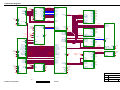
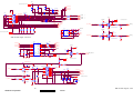
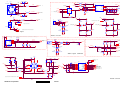
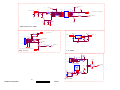
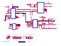
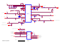
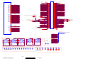
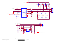
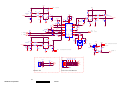
8 Schematic Diagrams
91
9. PCB Layout Diagrams
107
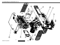
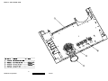
10. Exploded Diagrams
109
11. Recommended Spare Parts List
117
ii
ViewSonic Corporation
Confidential - Do Not Copy
PJ513D-1
1. Introduction
This section contains general service information, please read through carefully. It should be
stored for easy access place.
Important Service Information
Safety Notice
1
2
3
4
5
6
7
8
9
Make sure your working environment is dry and clean, and meets all government safety
requirements.
Ensure that other persons are safe while you are servicing the product.
DO NOT perform any action that may cause a hazard to the customer or make the product
unsafe.
Use proper safety devices to ensure your personal safety.
Always use approved tools and test equipment for servicing.
Never assume the product’s power is disconnected from the mains power supply. Check that
it is disconnected before opening the product’s cabinet.
Modules containing electrical components are sensitive to electrostatic discharge (ESD).
Follow ESD safety procedures while handling these parts.
Some products contain more than one battery. Do not disassemble any battery, or expose it
to high temperatures such as throwing into fire, or it may explode.
Refer to government requirements for battery recycling or disposal.
General Descriptions
This Service Manual contains general information. There are 3 levels of service:
Level 1: Cosmetic / Appearance / Alignment Service
Level 2: Circuit Board or Standard Parts Replacement
Level 3: Component Repair to Circuit Boards
1
ViewSonic Corporation
Confidential - Do Not Copy
PJ513D-1
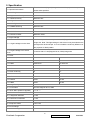
2. Specification
1.0 Optical Performance
1.1 ANSI Brightness
Tested under 60” (diagonal) image size with Wide projection lens position
unless other specified.
Minimum 1600 Lumens
1.2 Brightness Uniformity
1.2.1 ANSI Uniformity
Minimum 55%
1.2.2 Upper-Down unbalance
0.5~2
1.2.3 Left-Right unbalance
0.6~1.67
1.2.4 JBMA Uniformity
Minimum 60%
1.3 Contrast Ratio
1.3.1 ANSI Contrast
Minimum 150:1
1.3.2 FOFO Contrast
Minimum 1200:1
1.4 Light Leakage
<0.5 lux compared to center point within 60” (Diagonal at 2.2m, Wide)
1.4.1 Light Leakage in Active Area
image size. Note: This light leakage in Active area is only described as the
spot light with obvious shape. It is not included the uniformity difference of
the projector for black pattern.
1.4.2 Light Leakage out of Active
Area
<0.65 lux with 54”~80“(Diagonal at 2m, Wide) image size
1.5 Color
X
Y
1.5.1 White
0.312±0.04
0.354±0.04
1.5.2 Red
0.640±0.04
0.345±0.04
1.5.3 Green
0.355±0.04
0.548±0.04
1.5.4 Blue
0.141±0.04
0.087±0.04
1.6 Color Uniformity
X
Y
1.6.1 White
0.040
0.040
1.6.2 Red
0.040
0.040
1.6.3 Green
0.040
0.040
1.6.4 Blue
0.040
0.040
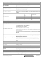
2.0 Image Quality
2.1 Throw Ratio
54”±5% Diagonal at 2m, Wide
2.2 Zoom Ratio (tolerance applied)
> 1.10 : 1
2.3 Distortion
2.3.1 Keystone Distortion
<1.0%
2.3.2 Vertical TV Distortion
<1.0%
2.3.3 Screen distortion
l W2-W1 l <6mm , l H2 –H1 l <6 mm
2.4 Projection Offset
120% ±5%
2.5 Focus Range
2.5.1 Visible Range
1~8 m
2
ViewSonic Corporation
Confidential - Do Not Copy
PJ513D-1
2.5.2 Clearly Focus Range
1.5~6 m(Spec. defined as item 2.6)
2.6 Focus
2.6.1 区 Pattern
(1)If pattern can be uniformly focused, pass!
(2)If not, check 2.6.2
Defocus: R<=3.0; G<=2.5; B<=2.5 pixel
2.6.2 Defocus and Flare
Flare: R<=4.0; G<=3.5; B<=3.5 pixel
Slight flare is not counted as flare.
2.6.3 Focus unbalance
Adjust focus from near to far until one corner clear, difference less than 70
cm@60”
Center of 49” diagonal
area
2.7 Lateral Color
All other area
R-G
<2/3
<1
G-B
<2/3
<1
R-B
<1
<1
2.8 Image Quality
2.8.1 DMD Image Quality
-
2.8.2 Image Imperfection
Procedure:
1. 54” (Diagonal at 2m, Wide) image size.
2. Default preset mode “ Dynamic”
2.8.3 Image Shadow or Blur
3. Full white pattern to check the image.
Let the projector on the desk (don’t move it up/down or left/ right) and just
inspect the pattern.
4. Compare to the limit sample of OOB. If blur or shadow worse than OOB,
than NG
1. When RGB value of content input is smaller than 20%, system will
automatically switch to Eco mode, if RGB value is greater than 60%, the
2.9 Dynamic Contrast Ratio (DCR)
projector will back to Normal mode.
2. When DCR function turns on, lamp mode function is grayed out to
disable; when DCR function turns off, lamp mode would return to setting
value.
3.0 Mechanical Specification
3.1 Dimensions
263 x 218 x 108mm (L x W x H)
3.2 Weight
2.6Kgw ± 0.1Kgw
3.3 Security Slot
Kensington compatible slot 150N break away force
3.5 Lens Cover
Detached Lens Cover
3.6 Feet
Fast adjustable foot in front, Adjustable foot and Fixed foot in rear. foot
Tilt:0-6∘,right/left: +2.2∘/-0.5∘
4.0 Packaging
4.1 Outside Dimensions
370 x 186 x 297mm (L x W x H)
4.2 Weight
3.76Kgw ± 0.1Kgw (Including Accessories, Projector).
3
ViewSonic Corporation
Confidential - Do Not Copy
PJ513D-1
72 units by Air;
4.3 Palletization
108 units (pallet A)/72 units (pallet B) by sea
2232 units/40’ container, or 1080 units /20’ container
5.0 Thermal Specification
Mechanical component temperature at ambience 0~40℃
Normal surface:
5.1 Surface held or touched for short
Metal < 60°C except screws & terminals
periods
Plastic<65°C except around ventilation (for this model only)
Screw and terminals <55°C
5.2 Surface which may be touched
5.3 Exhaust Air
Metal
Plastic
<70°C
<95°C
<95°C around ventilation holes
6.0 Environmental
6.1 Temperature
6.2 Humidity
Operating
0~40°C, without condensation
Storage
-20~60°C, without condensation
Operating
10~90%RH, without condensation
Storage
10~90%RH, without condensation
Typical
6.3 Audible Noise Level
Maximum
Normal mode: 32dBA @ 25°C
Eco mode: 28dBA @ 25°C
Normal mode: 34BA @ 25°C
Eco mode: 30dBA @ 25°C
Operating:
0~6000ft,25°C±5°C
6000ft~10000ft, 25°C±5°C must be operational and the reliability decrease
6.4 Altitude
is acceptable (not guarantee Power, Ballast, DMD and lamp life)
Storage:
0 to +40000ft sea level(-20 °C to 30°C)
Max altitude in 60°C :0-6500ft
Max temperature in 10000ft:53°C
Safety
7.0 Regulatory
CB, CSA, TUV-GS, CCC, PSB, NOM, Korean-eK, Gost-R,
Hygiene, SASO, TUV-Argentina, Ukraine, CE
EMC
FCC Class B requirements, CE
ESD
Qisda ESD Specification
8.0 Reliability
8.1 MTBF
8.2 Lamp Lifetime
40000 hours except DMD chip, Color wheel, Lamp and Ballast
Normal : 2000 hours (50% brightness maintenance)
Eco: 3000 hours
9.0 Power Requirements
Adhere to Appendix 3.5
9.1 Power Supply (Normal)
VAC 90 – 264 Auto-switch (50/60Hz), 3 Wire Grounded
9.2 Power consumption
Typical
260 W Max.
Standby
5W Max.
4
ViewSonic Corporation
Confidential - Do Not Copy
PJ513D-1
9.3 Power Connector
IEC-06
10.0 Panel Specification
10.1 Type
Single Chip 0.55” XGA 12 tilt DDR DMD Single Chip 0.55” SVGA 12 tilt LVDS DMD
10.2 Pixels
800 X 600
10.3 Color Depth
24 Bits (16770000 colors)
11.0 Compatibility
Adhere to Appendix 3
PC Compatible 640X480 Æ 800X600, compressed 1024 X
11.1 PC
768 1280X1024; Composite-Sync; Sync-on-Green; Interlace Mode
(8514A);
11.2 Video
NTSC/ NTSC4.43/ PAL (Including PAL-M, PAL-N)/ SECAM/ PAL60/
11.3 YpbPr
NTSC (480i)/ 480p/ PAL (576i)/ 576p, HDTV (720p/ 1080i)
11.4 DDC
DDC 2B
12.0 Image Interface
Adhere to Appendix 3.2
15 pin D-Sub (Female) x 1
12.1 Analog RGB Input
G(Y): Video amplitude 0.7/1.0 Vp-p : Impedance 75 RB(CbCr): Video amplitude 0.7 Vp-p : Impedance 75 HD/VD/CS: TTL Level
12.2 Video Input
RCA jack (Yellow)
Video amplitude 1.0 Vp-p : Impedance 75Ω
4 pin Mini-Din (Female)
12.3 S-Video Input
Y: Luminance amplitude 1.0 Vp-p : Impedance 75Ω
C: Chroma amplitude 0.268 Vp-p : Impedance 75Ω
12.4 YPbPr Input
15 pin D-Sub (Female) x 1 (Including 12.1)
Y: Luminance amplitude 1.0 Vp-p: Impedance 75Ω
PbPr/CbCr: Chroma amplitude 0.7 Vp-p : Impedance 75Ω
12.5 DVI-A Input
N/A
12.6 Analog RGB Output
15 pin D-Sub (Female) x 1
G: Video amplitude 0.7/1.0 Vp-p : Impedance 75 RB: Video amplitude 0.7 Vp-p : Impedance 75 HD/VD/CS: TTL Level
13.0 Control Interface
13.1 IR Receiver
IR Receiver x2 Angle: ±30° Distance 0~8m
13.2 Serial Connector
RS232 8pin Mini DIN
13.3 USB Connector
N/A
14.0 User Interface
Adhere to Appendix 3.3
9 Keys:
14.1 Operator Keypad
Power ; Source ; Auto; Left/Blank; Right/Panel key lock ; Mode/Enter ;
Up/Keystone+ ; Down/Keystone-; Menu/Exit
14.2 Indicators
3 LEDs:
Power On/Off Status; Lamp Status; Temperature Status
5
ViewSonic Corporation
Confidential - Do Not Copy
PJ513D-1
14.3 Electric Keystone
vertical keystone and adjustable range 40
15.0 Audio
15.1 Audio Input
15.2 Speaker
Φ3.5mm stereo mini jack x1
500mVrms, 10kΩ
Sound system: Mono
Speaker : 2Wx1
Amplifier: Philips PCA8551
Frequency Response: 100-20KHz
Distortion: Amplifier output 1W at 10% distortion
15.3 Audio Output
N/A
16.0 Option Box
16.1 Wireless function
N/A
16.2 Audio Output
N/A
16.3 LAN function
N/A
6
ViewSonic Corporation
Confidential - Do Not Copy
PJ513D-1
DDC Table (EDID FILE)
+0
00
20
7A
88
31
01
1C
00
30
00
00
00
20
0
10
20
30
40
50
60
70
80
90
100
110
120
Address
+1
FF
C5
00
23
59
01
20
1E
37
00
0A
FC
20
+2
FF
01
00
15
61
01
28
00
30
00
20
00
20
+3
FF
01
78
52
59
01
80
00
31
FD
20
50
20
+4
FF
01
0A
59
81
A0
14
00
30
00
20
4A
20
+5
FF
01
F1
AD
80
0F
00
FF
30
32
20
35
20
+6
FF
01
A7
CE
01
20
00
00
30
57
20
31
00
+7
00
11
A5
00
01
00
00
51
30
1E
20
33
51
+8
5A
01
56
45
01
31
00
54
31
64
00
44
+9
63
03
5D
59
01
58
00
59
0A
FF
00
0A
Data description
00 - 07 Fixed Data(EDID header)
08 - 09
10 -
ID Manufacturer Name: VSC = 5Ah 63h
(Alphabet number transformed to hex scale from binary)
11 ID Product Code: 20h, C5h
12 - 15 Not Used
16
Week of Manufacture: 01 (for example; variable)
17
Year of Manufacture: 2007 (for example; variable)
18
EDID Structure Version No.: 1
19
EDID Structure Revision No.: 3
20
Video Input Definition:
Analog Signal 0.700V/0.000V
Sync:
Separate
Set up
-
V Composite
Serration
Display Gamma: 2.2
24
DPMS Supported Feature:
V
-
21 - 22 Maximum Horizontal Image Size: 0cm
23
V On Green
Maximum Vertical Image Size: 0cm
Stand by
-
Suspend
-
Active off
-
Display Type: R/G/B color display Standard Default Color Space: unused
Preferred Timing Mode: supported GTF supported: not supported
25 - 34 Chroma Information:
35
36
Red
x = 0.634766
y =0.338867
Green
x = 0.368164
y = 0.544922
Blue
x = 0.147461
y =7.51953e-002
White
x = 0.313477
y = 0.34375
Established Timing I Support:
720X400 @70Hz
V 720X400 @88Hz
-
640X480 @60Hz
640X480 @72Hz
V 640X480 @75Hz
V 800X600 @56Hz
V 640X480 @67Hz
-
-
800X600 @60Hz
V
1024X768 @87Hz
-
Established Timing II Support:
800X600 @72Hz
V 800X600 @75Hz
V 832X624 @75Hz
1024X768 @60Hz
V 1024X768 @70Hz
V 1024X768 @75Hz
V 1280X1024 @75Hz
7
ViewSonic Corporation
Confidential - Do Not Copy
V-
PJ513D-1
37
Established Timing III Support:
Reserved
-
Reserved
- Reserved
-
Reserved
-
Reserved
-
Reserved
- Reserved
-
Reserved
-
38 - 53 Standard Timing Identification:
#1 60X480 @85Hz
#2 800X600 @85Hz
#3 1024X768 @85Hz
#4 1280X1024 @60Hz
#5 Non-Description
#6 Non-Description
#7 Non-Description
#8 Non-Description
54 - 125 Descriptor Description
54 - 71 Detailed Timing Description #1:
800x600 @60Hz
Pixel Clock = 40.00 MHz
Horizontal Image Size = 0 mm
Vertical Image Size = 0 mm
Refresh mode: Non Interlaced
Normal display, no stereo
Horizontal
Active Time = 800 pixels
Blanking Time = 256 pixels
Sync Offset = 40 pixels
Sync Pulse Width = 128 pixels
Border = 0 pixels
Frequency = 37.88 kHz
Vertical
Active Time = 600 lines
Blanking Time = 28 lines
Sync Offset = 1 lines
Sync Pulse Width = 4 lines
Border = 0 lines
Frequency = 60 Hz
Sync configuration: Digital Separate V sync: NEGA H sync: NEGA
72 - 89 Serial Number
(Each word to be transformed in ASCII code)
90 - 107 Monitor Description
Monitor Range Limits:
Vertical Frequency (min.) = 50Hz
Vertical Frequency (max.) = 87 Hz
Horizontal Frequency (min.) = 30 kHz
Horizontal Frequency (max.) = 100 kHz
Maximum Supported Pixel Clock = 110 MHz
GTF Standard is unused.
108 - 125 Monitor Description
Monitor Name: PJ513D
126
Extension Flag: 0
127
Checksum: 51 (for example; variable)
8
ViewSonic Corporation
Confidential - Do Not Copy
PJ513D-1
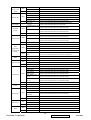
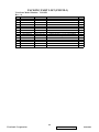
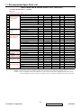
Screw List /Torque
Model name : PJ513D
No.
M2.0 1
Screw P/N
Description
Type
8F.1A522.6R0 MACH
Head
PHM
Length Coating
6
NI
Q’TY
1
Torque Where use
(kgf-cm)
2.5±0.5 Holder adjust foot & Fix block (1*)
Engine HSG & Power BD Shielding
2
8F.1G524.5R0 MACH
CAP
5
NI
1
4.5±0.5 (1*)
Blower BKT BTM & Lower Case(2*)
3
8F.VA564.6R0
TAP
(D-PT)
5.5±0.5
PHM
6
NI
12
8F.1A524.6R0 MACH
PHM
8
NI
2
Power Board S/W & Lower Case(2*)
Lamp Box & Lower Case(2*)
5.5±0.5
4
Ballast & Lower Case(3*)
Ceiling Mount Plate & Lower
Case(3*)
4.5±0.5 Lamp Door & Lower Case (2*)
M3.0
Blower BKT & Nozzle(1*)
5
8F.1A524.5R0 MACH
PHM
5
NI
8
4.5±0.5
Main BD Shielding & Power BD
Shielding(5*)
Speaker & Rear Cover (2*)
6
8F.VA564.100
7
8F.VG19.8R0
8
8F.VA564.8R0
9
8G.00020.423
TAP
(D-PT)
TAP
TAP
(D-PT)
NUT
PHM
10
NI
4
7.5±0.5 Upper Case & Lower Case(4*)
CAP
8
NI
3
7.0±0.5
PHM
8
NI
3
6.0±0.5 Engine HSG & Lower Case(3*)
HEX
3
NI
1
2.5±0.5 Rear adjust foot top(1*)
Lower Case & Power BD Shielding
(3*)
AC Wire & Power BD Shielding(1*)
M4.0 10 8F.1D526.6R0 MACH TAPTILE
8
NI
4
5.5±0.5 Ceiling Mount Plate & Lower
Case(3*)
#4-40 11 8F.00480.120
MACH
STAND
8
NI
4
4.5±0.5 Rear Case & D-SUB(4*)
9
ViewSonic Corporation
Confidential - Do Not Copy
PJ513D-1
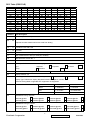
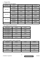
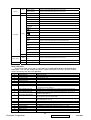
1. Timing Table
The Default timing is as following:
Resolution
Mode
Refresh rate (Hz)
H-frequency (kHz)
Clock (MHz)
720 x 400
720x400_70
70.087
31.47
28.322
VGA_60
59.940
31.469
25.175
VGA_72
72.809
37.861
31.500
VGA_75
75.000
37.500
31.500
VGA_85
85.008
43.269
36.000
SVGA_60
60.317
37.879
40.000
SVGA_72
72.188
48.077
50.000
SVGA_75
75.000
46.875
49.500
SVGA_85
85.061
53.674
56.250
XGA_60
60.004
48.363
65.000
XGA_70
70.069
56.476
75.000
XGA_75
75.029
60.023
78.750
XGA_85
84.997
68.667
94.500
SXGA3_60
60.020
63.981
108.000
640 x 480
800 x 600
1024 x 768
1280 x 1024
YPbPr support timing is as following:
Signal format
fh(kHz)
fv(Hz)
480i(525i)@60Hz
15.73
59.94
480p(525p)@60Hz
31.47
59.94
576i(625i)@50Hz
15.63
50.00
576p(625p)@50Hz
31.25
50.00
720p(750p)@60Hz
45.00
60.00
720p(750p)@50Hz
37.50
50.00
1080i(1125i)@60Hz
33.75
60.00
1080i(1125i)@50Hz
28.13
50.00
Video, S-Video support timing is as following:
Video mode
fh(kHz)
fv(Hz)
fsc(MHz)
NTSC
15.73
60
3.58
PAL
15.63
50
4.43
SECAM
15.63
50
4.25 or 4.41
PAL-M
15.73
60
3.58
PAL-N
15.63
50
3.58
PAL-60
15.73
60
4.43
NTSC4.43
15.73
60
4.43
10
ViewSonic Corporation
Confidential - Do Not Copy
PJ513D-1
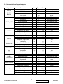
2. Characteristics of inputs/outputs
Signal
Parameter
RDATA
GDATA
BDATA
GDATA_SOG
HDATA
Min
Type
Max
Impedance
75
Ohm
Amplitude
0.7
Volts peak-to-peak
Black pedestal
0
Volts
Pixel Clock
110
M Hz
Impedance
75
Ohm
Amplitude
1
Volts peak-to-peak
Video amplitude
0.7
Volts peak-to-peak
Sync amplitude
0.3
Volts peak-to-peak
Black pedestal
0
Volts
Pixel Clock
110
M Hz
Impedance
1
K ohm
Amplitude, low level
0
0.8
volt
Amplitude, high level
2.5
5
Volt
Frequency
31
82
K Hz
Impedance
1
K ohm
Amplitude, low level
0
0.8
volt
Amplitude, high level
2.5
5
Volt
Frequency
48
85
Hz
Amplitude, low level
0
0.8
volt
Amplitude, high level
2.5
5
Volt
Amplitude, low level
0
0.8
volt
Amplitude, high level
2.5
5
Volt
RXD
Amplitude
-25
25
Volt
TXD
Amplitude
-25
25
Volt
VDATA
SDADATA
SCLDATA
Amplitude, total (video+ sync)
1
Volts peak to peak
Amplitude, video
0.7
Volts peak to peak
Amplitude, sync
0.3
Volts peak to peak
Impedance
75
ohm
Amplitude
300
m Volts peak to peak
Impedance
75
ohm
Impedance (audio in)
10
Kohm
CVBS
Luminance
CVBS Chroma
Audio
Amplitude (audio in)
0
0.30
Bandwidth
300Hz
16kHz
S/N Ratio
40
Total Harmonic Distortion
%
10
11
ViewSonic Corporation
Volts rms
Confidential - Do Not Copy
%
PJ513D-1
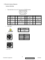
3. Electrical Interface Character
Interface Definition
•
15 pin definition of the mini D-sub male for DDC2B protocol
5
1
6
10
15
11
Pin
Definition
Pin
1
Red video
(Pr)
2
5
•
Definition
Pin
Definition
Pin
Definition
Green Video
(Y)
Red Video
Return
3
Blue Video
(Pb)
Green Video
Return
Monitor ID
bit 0
Data clock
(SCL)
4
NC
8
Blue Video
Return
Bi-directional
data (SDA)
NC
6
9
NC
10
Sync. Return
11
13
Horizontal
Sync
14
Vertical Sync
15
Pin
1
Composite input
S-Video input
4
3
2
•
12
Video Input
1
•
7
1
Definition
Composite video
input
Pin
1
2
Description
GND
GND
Luminance
Chroma
3
4
Control Port
8
7
5
6
4
2
3
1
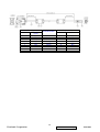
RS232 cable :
12
ViewSonic Corporation
Confidential - Do Not Copy
PJ513D-1
PC side
Function
CONN1
name
3
TXD
7
RTS
4
NC
5
GND
8
CTS
1
NC
2
RXD
9
NC
6
NC
COLOR of Wire
Black
Brown
Red
Orange
Yellow
Green
Blue
White
Projector side
CONN2
Function name
1
2
3
4
5
6
7
8
RXD
CTS
NC
GND
RTS
NC
TXD
NC
13
ViewSonic Corporation
Confidential - Do Not Copy
PJ513D-1
4. Functionality
The Following functionality will be supported: (Detailed description refer to SW Specification)
Functionality
Data (Computer)
Video/S-Video
YPbPr/YCbCr
Preset Mode
YES
YES
YES
Brightness
YES
YES
YES
Contrast
YES
YES
YES
Color
NO
YES
YES
Tint
NO
YES
YES
Sharpness
NO
YES
NO
Color Temp
YES
YES
YES
H. Position
YES
NO
YES
V. Position
YES
NO
YES
H. Phase
YES
NO
YES
H. Size
YES
NO
YES
Keystone
YES
YES
YES
Language
YES
YES
YES
Auto
YES
YES
YES
Image Ratio
YES
YES
YES
Auto Off
YES
YES
YES
Mirror
YES
YES
YES
Source
YES
YES
YES
Freeze
YES
YES
YES
Blank
YES
YES
YES
Lamp Reset
YES
YES
YES
OSD Timer
YES
YES
YES
Source Scan
YES
YES
YES
Keystone Hold
YES
YES
YES
Mirror Hold
YES
YES
YES
Blank Time
YES
YES
YES
Information
YES
YES
YES
Reset
YES
YES
YES
External Message indicator (Detailed description refer to SW Specification)
Message
Occasion
PC/Composite Video /S-Video /Analog YPbPr Searching
The system does not detect the signal
Out of range
The signal is over the specification
NOTICE :Order replacement lamp , Lamp > 2000 hours
Lamp Hour is over 2000 hours
NOTICE: Replacement lamp soon, Lamp > 2950 Hours
Lamp Hour is over 2950 hours
NOTICE: Replacement lamp Now, Lamp > 3000 Hours,
Lamp Hour is over 3000 hours.
Lamp-usage time exceeded.
14
ViewSonic Corporation
Confidential - Do Not Copy
PJ513D-1
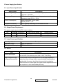
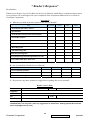
5 Power Supply Specification
5.1. Input Power Specification
Specification
Description
Input Voltage Range
The unit shall meet all the operating requirements with the
range 90 ~ 264 VAC
Frequency Range
The unit shall meet all the operating requirements with an input
frequency range 50 Hz ~ 60 Hz
Power Consumption
Normal operation: 260 W (Max)
standby mode: < 5 W
Regulation Efficiency
80 % (typical) measuring at 115Vac and full load
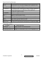
5.2. Output Power Requirement
The power supply can provide DC output as below:
NO.
Voltage
1
2
Regulation
Load Current Range
Ripple & Noise
+5 V
±5 %
0.06A ~ 0.5 A
100 mV
+12 V
±10 %
0.04 A ~ 1.25A
300 mV
5.3. Lamp Power specifications
Specification
Description
Applicable Lamp
180W, AC operation
Starting pulse from Ignitor
2.5KV
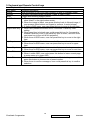
5.4. Others
Item
Power good signal
High voltage and high
temperature protection
Description
Active high after 5 Volt reach 95% of its rating and goes to logic
low at least 0.5ms before power falls to 90% of its rating
To avoid user from the dangerous of HV and high temperature,
when front door of lamp case is opened whether intentionally or
accidentally, the power should be disconnected immediately.
When the door is closed again, the igniter restart sequence should
be compliant to that is described previously
15
ViewSonic Corporation
Confidential - Do Not Copy
PJ513D-1
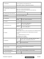
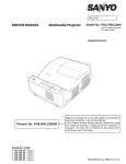
3. Keyboard and Remote Control keys
Local Keyboard Description
Key Name
Detailed Description
Power
Use this button to turn your Data Projector on and off (standby mode).
Source
To select input sources as Computer, Video, S-Video, YpbPr
Auto
Toggle auto-tracking image function
Left/Blank
1. When user presses the button once, the image would turn to blank and
show “blank” in the right-button screen.
2. When the image is blank, user press this key back to Normal image; if
user presses other buttons on keypad or remove, it would release
3. If there is OSD menu, user can press this key to move to the left item.
Right/Panel Key 1. When user presses the button once, it will enter “Panel key Lock”
setting.
2. When panel key is locked, user could press this key for 3 seconds to
release Panel Key Lock( If the panel key lock is active, user still could
use power key to turn on/off the projector)\
3. When there is OSD menu, user can press this key to move to the right
item
Up/Keystone+
1. When user presses this button once, it will increase the keystone value.
2. When there is OSD menu, user can press this key to move to upper
item.
Down/Keystone- 1. When user presses this button once, it will decrease the keystone value.
2. When there is OSD menu, user can press this key to move to next item.
Menu/Exit
1. User could press this button to call OSD
2. When it exists OSD, user could press this button to leave current page
to main menu or to close OSD.
Mode/Enter
1. When there is No OSD menu, this button is Mode hot key; user would
press this button to choose one of preset modes.
2. When there is confirm messages, user could press this key to confirm
selection.
16
ViewSonic Corporation
Confidential - Do Not Copy
PJ513D-1
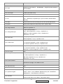
Remote Control Keys Description
IR-Key Name
Detailed Description
Power
Use this button to turn your Data Projector on and off (standby mode).
Source
To select input sources as Computer, YPbPr , Video, S-Video
Menu/Exit
(1) OSD pop-up. (2) Close OSD or leave current page
4/Panel Key
(1) Press once, enter ”Panel Key Lock” setting. (2) Press 3 seconds to
release “Panel Key Lock”. (3) OSD menu, move to right items
3
5/Keystone+
(1) OSD menu, move to left item.
6/Keystone-
(1) Keystone-. (2) Move item bar
Auto
Toggle auto-tracking image function
Mode/Enter
(1) Change different Preset mode (2) Press for confirm message.
Freeze
This button will freeze a picture. Press again to resume motion.
Blank
Press “Blank” key first to blank the screen.
Digital Zoom +
(1) Zoom in (2) Pan the picture , when picture is in Zoom in/out image.
Digital Zoom -
(1) Zoom out (2) Pan the picture, when picture is in Zoom in/out image.
(1) Keystone+. (2) Move to page level
External Status indicator
LED Name
Detailed Description
Power LED
Display the power on/off sequence status
Lamp Status LED
Display the Lamp status (Lamp fail, Lamp spoil etc.)
Temperature Status LED
Display the Thermal status (Fan Fail, Over Temperature, etc.)
17
ViewSonic Corporation
Confidential - Do Not Copy
PJ513D-1
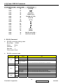
4. IR Code / RS232 Command
1. IR Code
CUSTOMER CODE DATA CODE
FUNCTION
0030
02
POWER
0030
03
0030
04
SOURCE
0030
05
TIMER (ON)
0030
06
TIMER (SETUP)
0030
07
BLANK
0030
08
AUTO
0030
0B
0030
0C
0030
0D
0030
0E
0030
0F
MENU
0030
10
MODE
0030
18
DIGITAL ZOOM +
0030
19
DIGITAL ZOOM -
2. RS-232 Command
a. RS-232 connection setting value
Baud Rate: 115200
Parity:
None
Data bits:
8
Stop bits:
1
Flow control: None
b.
RS-232 command code
Function
Status
Write
Power
Action
Turn on
0x06 0x14 0x00 0x03 0x00 0x34 0x11 0x00 0x5C
Turn off
0x06 0x14 0x00 0x03 0x00 0x34 0x11 0x01 0x5D
Power
Read
status( on/off/cool
down)
Excute
Reset
Mirror
Write
Read
Contrast
(only For User
Mode)
cmd
Write
Read
0x07 0x14 0x00 0x05 0x00 0x34 0x00 0x00 0x11 0x00 0x5E
0x06 0x14 0x00 0x03 0x00 0x34 0x11 0x02 0x5E
Normal
0x06 0x14 0x00 0x04 0x00 0x34 0x12 0x00 0x00 0x5E
H Inverse
0x06 0x14 0x00 0x04 0x00 0x34 0x12 0x00 0x01 0x5F
V Inverse
0x06 0x14 0x00 0x04 0x00 0x34 0x12 0x00 0x03 0x61
H&V Inverse
0x06 0x14 0x00 0x04 0x00 0x34 0x12 0x00 0x02 0x60
Mirror status
0x07 0x14 0x00 0x05 0x00 0x34 0x00 0x00 0x12 0x00 0x5F
Contrast decrease
0x06 0x14 0x00 0x04 0x00 0x34 0x12 0x02 0x00 0x60
Contrast increase
0x06 0x14 0x00 0x04 0x00 0x34 0x12 0x02 0x01 0x61
Contrast ratio
0x07 0x14 0x00 0x05 0x00 0x34 0x00 0x00 0x12 0x02 0x61
18
ViewSonic Corporation
Confidential - Do Not Copy
PJ513D-1
Brightness
(only For User
Mode)
Aspect ratio
Write
Read
Write
Read
Brightness decrease
0x06 0x14 0x00 0x04 0x00 0x34 0x12 0x03 0x00 0x61
Brightness increase
0x06 0x14 0x00 0x04 0x00 0x34 0x12 0x03 0x01 0x62
Brightness
0x07 0x14 0x00 0x05 0x00 0x34 0x00 0x00 0x12 0x03 0x62
Aspect ratio Auto
0x06 0x14 0x00 0x04 0x00 0x34 0x12 0x04 0x00 0x62
Aspect ratio Native
0x06 0x14 0x00 0x04 0x00 0x34 0x12 0x04 0x01 0x63
Aspect ratio 4:3
0x06 0x14 0x00 0x04 0x00 0x34 0x12 0x04 0x02 0x64
Aspect ratio 16:9
0x06 0x14 0x00 0x04 0x00 0x34 0x12 0x04 0x03 0x65
Aspect ratio
0x07 0x14 0x00 0x05 0x00 0x34 0x00 0x00 0x12 0x04 0x63
Auto Adjust
Excute
0x06 0x14 0x00 0x03 0x00 0x34 0x12 0x05 0x62
Horizontal position shift
Horizontal
Write
position
Read
right
0x06 0x14 0x00 0x04 0x00 0x34 0x12 0x06 0x01 0x65
Horizontal position shift
left
0x06 0x14 0x00 0x04 0x00 0x34 0x12 0x06 0x00 0x64
Horizontal position
0x07 0x14 0x00 0x05 0x00 0x34 0x00 0x00 0x12 0x06 0x65
Vertical position shift
Vertical position
Write
Read
Color
temperature
Write
(only For User
Mode)
Read
Blank
Keystone-Vertical
0x06 0x14 0x00 0x04 0x00 0x34 0x12 0x07 0x00 0x65
down
0x06 0x14 0x00 0x04 0x00 0x34 0x12 0x07 0x01 0x66
read Vertical position
0x07 0x14 0x00 0x05 0x00 0x34 0x00 0x00 0x12 0x07 0x66
color temperatureT1
0x06 0x14 0x00 0x04 0x00 0x34 0x12 0x08 0x00 0x66
color temperatureT2
0x06 0x14 0x00 0x04 0x00 0x34 0x12 0x08 0x01 0x67
color temperatureT3
0x06 0x14 0x00 0x04 0x00 0x34 0x12 0x08 0x02 0x68
color temperatureT4
0x06 0x14 0x00 0x04 0x00 0x34 0x12 0x08 0x03 0x69
color temperature
status
0x07 0x14 0x00 0x05 0x00 0x34 0x00 0x00 0x12 0x08 0x67
Write
Blank on/off
0x06 0x14 0x00 0x03 0x00 0x34 0x12 0x09 0x66
Read
Blank status
0x07 0x14 0x00 0x05 0x00 0x34 0x00 0x00 0x12 0x09 0x68
Write
Read
Preset mode
up
Vertical position shift
Write
Decrease
0x06 0x14 0x00 0x04 0x00 0x34 0x12 0x0A 0x00 0x68
Increase
0x06 0x14 0x00 0x04 0x00 0x34 0x12 0x0A 0x01 0x69
Keystone status
0x07 0x14 0x00 0x05 0x00 0x34 0x00 0x00 0x12 0x0A 0x69
Preset mode 0
0x06 0x14 0x00 0x04 0x00 0x34 0x12 0x0B 0x00 0x69
Preset mode 1
0x06 0x14 0x00 0x04 0x00 0x34 0x12 0x0B 0x01 0x6A
Preset mode 2
0x06 0x14 0x00 0x04 0x00 0x34 0x12 0x0B 0x02 0x6B
Preset mode 3
0x06 0x14 0x00 0x04 0x00 0x34 0x12 0x0B 0x03 0x6C
Preset mode 4 (PC
User I)
0x06 0x14 0x00 0x04 0x00 0x34 0x12 0x0B 0x04 0x6D
Preset mode 5 (PC
Freeze
Source input
User II )
0x06 0x14 0x00 0x04 0x00 0x34 0x12 0x0B 0x05 0x6E
Read
Preset mode status
0x07 0x14 0x00 0x05 0x00 0x34 0x00 0x00 0x12 0x0B 0x6A
Write
Freeze on/off
0x06 0x14 0x00 0x03 0x00 0x34 0x13 0x00 0x5E
Read
Freeze status
0x07 0x14 0x00 0x05 0x00 0x34 0x00 0x00 0x13 0x00 0x60
Input source VGA
0x06 0x14 0x00 0x04 0x00 0x34 0x13 0x01 0x00 0x60
Input source YPbPr
0x06 0x14 0x00 0x04 0x00 0x34 0x13 0x01 0x04 0x63
Write
Composite
Read
Source scan
Write
Read
Mute
Input source
Write
Read
0x06 0x14 0x00 0x04 0x00 0x34 0x13 0x01 0x05 0x65
Input source SVIDEO
0x06 0x14 0x00 0x04 0x00 0x34 0x13 0x01 0x06 0x66
Source
0x07 0x14 0x00 0x05 0x00 0x34 0x00 0x00 0x13 0x01 0x61
Source scan on
0x06 0x14 0x00 0x04 0x00 0x34 0x13 0x02 0x01 0x62
Source scan off
0x06 0x14 0x00 0x04 0x00 0x34 0x13 0x02 0x00 0x61
Source scan status
0x07 0x14 0x00 0x05 0x00 0x34 0x00 0x00 0x13 0x02 0x62
Mute on
0x06 0x14 0x00 0x04 0x00 0x34 0x14 0x00 0x01 0x61
Mute off
0x06 0x14 0x00 0x04 0x00 0x34 0x14 0x00 0x00 0x60
Mute status
0x07 0x14 0x00 0x05 0x00 0x34 0x00 0x00 0x14 0x00 0x61
19
ViewSonic Corporation
Confidential - Do Not Copy
PJ513D-1
Write
Volume
Read
Write
Language
Read
Lamp Time
Write
Read
error status
Increse Volume
0x06 0x14 0x00 0x03 0x00 0x34 0x14 0x01 0x60
Decrese Volume
0x06 0x14 0x00 0x03 0x00 0x34 0x14 0x02 0x61
Volume
0x07 0x14 0x00 0x05 0x00 0x34 0x00 0x00 0x14 0x03 0x64
English
0x06 0x14 0x00 0x04 0x00 0x34 0x15 0x00 0x00 0x61
Français
0x06 0x14 0x00 0x04 0x00 0x34 0x15 0x00 0x01 0x62
Deutsch
0x06 0x14 0x00 0x04 0x00 0x34 0x15 0x00 0x02 0x63
Italiano
0x06 0x14 0x00 0x04 0x00 0x34 0x15 0x00 0x03 0x64
Español
0x06 0x14 0x00 0x04 0x00 0x34 0x15 0x00 0x04 0x65
РУССКИЙ
0x06 0x14 0x00 0x04 0x00 0x34 0x15 0x00 0x05 0x66
繁體中文
0x06 0x14 0x00 0x04 0x00 0x34 0x15 0x00 0x06 0x67
简体中文
0x06 0x14 0x00 0x04 0x00 0x34 0x15 0x00 0x07 0x68
日本語
0x06 0x14 0x00 0x04 0x00 0x34 0x15 0x00 0x08 0x69
한국어
0x06 0x14 0x00 0x04 0x00 0x34 0x15 0x00 0x09 0x6A
Swidish
0x06 0x14 0x00 0x04 0x00 0x34 0x15 0x00 0x0a 0x6B
Dutch
0x06 0x14 0x00 0x04 0x00 0x34 0x15 0x00 0x0b 0x6C
Turkish
0x06 0x14 0x00 0x04 0x00 0x34 0x15 0x00 0x0c 0x6D
Czech
0x06 0x14 0x00 0x04 0x00 0x34 0x15 0x00 0x0d 0x6E
Portugese
0x06 0x14 0x00 0x04 0x00 0x34 0x15 0x00 0x0e 0x6F
Thai
0x06 0x14 0x00 0x04 0x00 0x34 0x15 0x00 0x0f 0x70
Polish
0x06 0x14 0x00 0x04 0x00 0x34 0x15 0x00 0x10 0x71
Language
0x07 0x14 0x00 0x05 0x00 0x34 0x00 0x00 0x15 0x00 0x62
Reset Lamp usuage
hour
Lamp usuage hour
Read
0x06 0x14 0x00 0x03 0x00 0x34 0x15 0x01 0x61
0x07 0x14 0x00 0x05 0x00 0x34 0x00 0x00 0x15 0x01 0x63
0x07 0x14 0x00 0x05 0x00 0x34 0x00 0x00 0x15 0x02 0x64
Error code table
To send Hex code “error status” read “0x07 0x14 0x00 0x05 0x00 0x34 0x00 0x00 0x15
0x02 0x64”. User can get 20 byte data which mapping to below error status and the number
means how many time the error appeared.
Byte
0
1
2
3
4
5
6
7
Error Name
LampFailCount
Fan1ErrorCount
Fan2ErrorCount
Fan3ErrorCount
Fan4ErrorCount
Diode1OpenErrorCount
Diode2OpenErrorCount
Diode3OpenErrorCount
8
9
10
Diode1ShortErrorCount
Diode2ShortErrorCount
Diode3ShortErrorCount
11
Temperature1ErrorCount
12
Temperature2ErrorCount
13
14
15
16
17
18
19
Temperature3ErrorCount
FanIC1ErrorCount
FanIC2ErrorCount
WatchdogCount
AbnormalPowerdown
CWErrorCount,
FirstBurnInErrorMinutes
Description
Lamp turn on fail
Fan1 fail (lamp fan)
Fan2 fail (power fan)
Fan3 fail (blower fan)
Fan4 fail (The model without 4 fans without this error count)
Thermal sensor 1 lose connection
Thermal sensor 2 lose connection
Thermal sensor 3 lose connection (The model without thermal sensor 3
is no function for this address)
Thermal sensor 1 short (inlet sensor which located at main board)
Thermal sensor 2 short (power board temperature sensor)
Thermal sensor 3 short (The model without thermal sensor 3 is no
function for this address)
Thermal sensor 1 detect temperature over system limitation (inlet
sensor which located at main board)
Thermal sensor 2 detect temperature over system limitation (power
board temperature sensor)
Thermal sensor 3 detect temperature over system limitation (No used)
Fan IC 1 fain (G743 or G794)
No used
The DDP2230 internal F/W watchdog function executed
The user turn off unit without finish cooling process
Color wheel do not spin
st
The timeframe from burn-in to 1 time shutdown in minute.
20
ViewSonic Corporation
Confidential - Do Not Copy
PJ513D-1
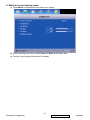
4. Method to enter factory menu:
a) Press Menu on keypad than the main menu popup
b) When showing main menu, press Source + Mode at the same time
c) Factory menu popup at the top-left of display
21
ViewSonic Corporation
Confidential - Do Not Copy
PJ513D-1
5. Adjustment Procedure
Visual Inspection & Cleaning
Visual Inspection Criteria
1.0 Inspection zone definition and inspection distance
A-side:
Up case
- Up case surfaces except right / left / behind side’s surface.
Front cover - Front cover surface
B-side:
Side
- right/left sides surfaces
Back cover - Back cover surfaces
C-side:
Low cause
- bottom surfaces
z
For spot inspection distance is 45 cm on A/B/C-side. And inspection time is 10 sec.
z
For scratch inspection distance is 45 cm on A/B/C-side. And inspection time is 10 sec.
1.1 Appearance Inspection Criteria
1.1.1 Environment Condition
1.1.1.1 Lighting intensity
All appearance quality shall be inspected with the lighting condition as 500~800Lux
(natural lighting or white fluorescent light).
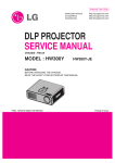
1.1.1.2 Inspection angle and distance to object or target
All part inspection must be done under direct overhead lighting. Viewing angle and
distance are dependent on surface classification. In all cases, parts must be held in such
that the light reflection does not disturb the inspector's eye.
Figure 1
22
ViewSonic Corporation
Confidential - Do Not Copy
PJ513D-1
Table 1
Classification
Area A
Lighting positioning
Area B
Area C
Above of inspected part
Inspection position relative to part
90º
90º
90º
Inspection distance
40~50 cm
40~50 cm
40~50 cm
1.1.1.3 Inspection interval (time)
Inspection interval is a function of surface area.
Time for visual inspection: 10sec.
Table 2
Parts Size
“A” surface
“B” surface
“C” surface
Time
10 sec
10 sec
10 sec
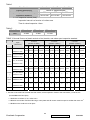
TABLE 3 General Product of plastic outlook of dot, blemish, and others spec inspection standard
Spec
( Area cm2 )
P < 0.2 mm2
Distance ≥ 2cm
|
Color
spot
0.3≦P <0.4mm2
Distance ≥ 4cm
Distance ≥ 2cm
Particle
0.1≦P<0.2mm2
|
Distance ≥ 4cm
Distance ≥ 4cm
color
0.3≦P < 0.5mm2
(Number of defect)
(Number of defect)
(Number of defect)
70*70 100*100 20*20
Distance ≥ 5cm
Total
Ignore
50*50
70*70 100*100 20*20
Ignore Ignore Ignore Ignore
50*50 70*70 100*100
Ignore Ignore Ignore Ignore
2
3
4
5
2
3
4
5
4
4
5
6
0
0
0
0
2
3
4
5
3
4
5
6
Ignore Ignore Ignore
Spot with 0.2≦P < 0.3mm2
same
C surface
Ignore Ignore Ignore
Distance ≥ 4cm
P<0.1 mm2
B surface
20*20 50*50
Particle 0.2≦P< 0.3 mm2
Blemish
A surface
Ignore
Ignore Ignore Ignore Ignore
Ignore Ignore Ignore Ignore
4
4
5
6
5
5
6
7
6
6
7
8
3
4
4
5
4
5
5
6
6
7
7
8
2
2
3
4
3
3
4
5
4
4
5
6
4
4
5
6
5
5
6
7
6
6
7
8
Note:
1. Use the 20*20 criteria to the area less than 20*20; 50*50 inspection criteria to the area 20*20≦A<50*50; etc.
(Particle/Blemish/Color Spot)
1.1 Definition of surface A, B, C refer to 6.2
1.2 Blemish around the ViewSonic Bird logo, name plate and silk screen must be equal or smaller than 0.05 mm2
1.3 Bubble on the surface is to be reject.
23
ViewSonic Corporation
Confidential - Do Not Copy
PJ513D-1
TABLE 2 : General Product of plastic outlook inspection standard
NO Appearance
1
Shrinkage
Spec
A region: No Shrink. With gloves, no feeling of sink when touching the surface
B/C region: not obvious
2
Run, Texture, Gloss
No obvious non-uniformity
3
Welding Line/Knit Line Follow limit sample level
4
Ejector Mark
5
Label/screws shortage Reject
6
Material shortage
Not allow, Reject
7
Chromatic aberration
Follow engineering specification
8
Printing
Printing must not have incomplete printing, break off, overlap, uneven thickness,
Reject
excessive ink, printing misalignment (1.5mm), printing slanting & crooked (<0.5mm)
Printing color must be comparable to color chip and sample. Follow engineering
specification
9
Logo of panel sticker
Printing must not have incomplete printing, break off, overlap, uneven thickness,
excessive ink, printing misalignment (1mm), printing slanting & crooked (<0.5mm)
Printing color must be comparable to color chip and sample.
10 Scratch/Nicks
Side A:
(W < 0.1mm , L < 5mm): Only 2 this kind of scratch is accepted
W < 0.1mm , L < 5-10mm :Only 1 this kind of scratch is accepted
Side B:
W < 0.2mm , L < 5mm : Only less than 2 this kind of scratch is accepted
W < 0.2mm , L < 5-10mm : Only 1 this kind of scratch is accepted
Side C:
W < 0.3mm , L < 5mm : Only 3 this kind of scratch is accepted
W < 0.3mm , L < 5-10mm : Only 2 this kind of scratch is accepted
W < 0.3mm , L < 10-15mm: Only 0 this kind of scratch is accepted
Note:
1. Severe scratch which disclose the Natural
2. When light scratching on it, there’s no feeling of obstruction. Also, there should not
be obvious difference in gloss nearby it.
3. Each scratch should be 5cm more far away from each other
4. Front case must be no any scratch
24
ViewSonic Corporation
Confidential - Do Not Copy
PJ513D-1
PART II
Operational Inspection Criteria
TEST CONDITIONS
Unless other prescription, the test conditions are as followings:
Nominal voltage: refer to operation manual
Environmental illumination:
Variable from 500 to 800 Lux (For appearance inspection)
Variable from 0 to 7 Lux (For functional inspection)
Temperature: 25±5℃
Visual inspection shall be done with the distance from eyes to the sample 45
cm.
Display mode: refer to operation manual
TEST EQUIPMENTS
Dark room
PC
Pattern Generator: Chroma 2327 or equivalent
Minolta color analyzer CL200 or equivalent device with accredited traceability
DVD player
Power supply (100~240 VAC) with consumption meter
Measuring tape
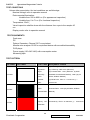
TEST PATTERN
PATTERN
PATTERN
Full white
Full Dark
Full Red
TEST ITEM
Acceptance Criteria
ANSI
(1) ANSI Brightness:(Normal Mode) 1600lm
Brightness、
(2) Uniformity: ANSI: 55% (Minimum)
Bright
(3) Contrast Ratio : 150:1 (Minimum, by ANSI
Uniformity、
Standard Checkerboard Method), 1200:1(by All
FOFO
White, All Black Method)
Contrast
(4) White Point, Color :x = 0.312±0.04, y =
Ratio、
0.354±0.04
FOFO
Contrast Ratio : 1200:1(by All White, All Black
Contrast Ratio
Method)
Impurity、CIE
Chromaticity : Red: x =0.640±0.04, y= 0.345±0.04
coordinate
25
ViewSonic Corporation
Confidential - Do Not Copy
PJ513D-1
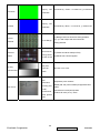
Full Green
Full Blue
Chromo
800x600
General-1
pattern
16 Gray
and Color bar
Impurity、CIE
Chromaticity : Green: x =0.355±0.04, y=0.548±0.04
coordinate
Impurity、CIE
coordinate
Chromaticity : Blue: x =0.141±0.04, y= 0.087±0.04
(1)Background lines should be distinguishable.
Focus Range
(2)“区”:Letter shape and lines should be
distinguishable.
Performance/
Timing check/
function check
(1)Phase should be stable(no flick)
(2)Whole frame should appear.
Gray and
Color bar
No lack or mix color
Check
Check the
DDC
information,
DDC check
Including S/N,
model,
manufacturer
name, product
S/N(08-09): with numbers
Model(108-125) with numbers(ref Appendix DDC
table)
manufacturer name(08-09):5A63
product ID code (10-11): 20C5
code.
26
ViewSonic Corporation
Confidential - Do Not Copy
PJ513D-1
Software/Firmware Upgrade Process
How to Download Firmware
Hardware required
1. Standard RS-232 Download cable
2. Personal computer or laptop computer
Software required
1. DDP2230 Composer lite
2. New version FW
DDP2230 Composer lite install procedure
Installation Location
The default installation directory is:
C:\Program Files\DLP Composer Lite 7.0
If you want to install to a different directory (perhaps alongside a prior release of DLP
Composer™ Lite), click the "Browse" button on the "Select Features" page..
USB Support - Installation (All Platforms)
This release includes support for a USB communications interface to DDP2230-based
projectors. The setup program includes the files needed to install USB support (for
Win98/WinMe/Win2K/WinXP only -- Win95 and WinNT are not supported).
After DLP Composer™ Lite is installed, to install the USB support, choose the "Install
DDP2230 USB Driver" icon under "DLP Composer™ Lite" in your Start menu.
USB Support - Win98/Me/XP Only
Installation on Windows 98/Me//XP may prompt "Please insert the disk labeled 'DLP
Composer Installation Directory', and then click OK". This message may be safely ignored
by clicking the OK button.
Another prompt will then appear: "The file 'windrvr6.sys' on DLP Composer Installation
Directory cannot be found".
problems.
Again, click OK and the installation proceeds without further
27
ViewSonic Corporation
Confidential - Do Not Copy
PJ513D-1
USB Support - Using a projector for the first time
After installation is complete, and you plug a DDP2230-based projector into USB for the first
time, Windows will run the "New Hardware Wizard". When the wizard prompts to find the
necessary drivers, accept the recommended choice (let the system find the driver for you)
and click "Next" to complete the installation.
Note: The Windows 98/Me/XP "New Hardware Wizard" may not automatically find the
driver. You should use the "Advanced" option, and enter the directory where the DLP
Composer™ Lite Tool Suite was installed (normally "C:\Program Files\DLP Composer
Lite"). The wizard will find the file "DDP2230.inf" and complete the installation.
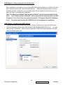
USB Support - Choosing the USB interface
To select the USB communications interface, choose "Preferences" from the "Edit" menu,
click the "Communications" page and choose "USB (DDP2000/DDP3020 Only)". You can
now use DLP Composer™ Lite to communicate with a DDP2230-based projector via USB
using the Flash Loader tool.
28
ViewSonic Corporation
Confidential - Do Not Copy
PJ513D-1
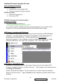
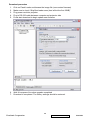
Download procedure
1. Click on Flash Loader and browse the image file (new version firmware)
2. Make sure to check “Skip Boot loader area (load all but the first 32KB)”
3. Plug power cord into projector
4. Plug in RS-232 cable between computer and projector side
5. Press start download to begin update new firmware
6.
7.
Wait till composer lite notice upgrade completed
Download is completed. The factory settings should be restored.
29
ViewSonic Corporation
Confidential - Do Not Copy
PJ513D-1
1. EE Assembly and Alignment Concern:
1. Color Wheel Delay Alignment
Equipment:
- Battery Biased Silicon PIN Detector
- Oscilloscope
- Probe
OSD Default value:
Item
Value
DLP Brightness
32
DLP Contrast
32
White Peak
10
Item
Value
CW Delay
Adjustable
The default values let optical engine to get maximum contrast and brightness.
Procedure:
Probe impedance matches 50 ohm
Open Factory OSD, and select color wheel delay item
Leave the image pure red (DMD red curtain)
Put the detector on the screen that red image was projected.
Watch the oscilloscope and notice the square waveform
Use the “Æ” and “Å” key to increment or decrement the color wheel delay value
No matter the waveform is square or not, let the waveform was lagged first
Lag
Exact
Ahead
Then increment or decrement the value to let the waveform to be square
Do not adjust too much, let the signal get ahead, if it happens, go back to step 7 and do it again.
Change the input to pure blue and repeat the above procedures again.
Change the input to pure green and repeat the above procedures again.
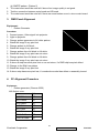
2. Main board check procedure
Equipment:
- Pattern generator
Procedure:
1. Connect power, D-sub into projector.
2. Light on projector.
3. Testing below patterns and resolution is 854*480@60Hz (480P)
(1) General-1 pattern. (Pattern 1)
(2) 32 grays pattern. (Pattern 48)
(3) White pattern. (Pattern 41)
30
ViewSonic Corporation
Confidential - Do Not Copy
PJ513D-1
(4) SMPTE pattern. (Pattern 5)
4. The main board would be note fail if above four image-quality is not good.
5. Test the connection between main board and IR board.
6. The main board would be note fail if there are some broken occur in wire or main board.
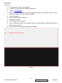
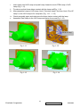
3. DMD Panel Alignment
Equipment:
-
Pattern Generator
Procedure:
1. Connect power, Video signal into projector.
2. Light on projector
3. Change pattern generator to full white pattern.
4. Watch the image if any pixel lost
5. Change pattern to full black.
6. Watch the image if any pixel lost
7. Change pattern from full black to full white.
8. Watch the image if any pixel can not return
9. Change pattern from full black to full white.
10. Watch the image if any pixel can not return
11. If above 8 step has some pixel lost or can not return, it’s DMD chip has pixel defect
12. Change to the Slid Line pattern
13. Watch the image if any pixel lost
14. If above step has some pixel lost, it’s conductive socket has defect or assembly loosed.
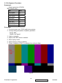
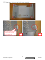
4. PC Alignment Procedure
Equipment:
-
Pattern generator (Chroma-2250)
OSD Default value:
Item
Value
Cal R Offset
127
Cal G Offset
127
Cal B Offset
127
Cal R Gain
127
Cal G Gain
127
Cal B Gain
127
YPbPr R Offset
127
YPbPr B Offset
127
31
ViewSonic Corporation
Confidential - Do Not Copy
PJ513D-1
Procedure:
Gray Level:
1.
2.
3.
4.
Connect power, D-sub, into projector.
Change Timing and pattern of pattern generator:
Timing: 800*600@60
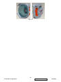
Pattern: As Figure1 {A near white color (240,240,240) and a near black color(16,16,16),
the area of white is 101/200, black is 99/200}
5. Light on projector
6. Set user OSD values to default.
7. Enter factory mode.
8. Set Factory values to default.
9. Press “Calibration RGB” to let the black level to just distinguish, and the light output of
white level to just max.
10. Check the 32 levels of gray. All steps must appear.
Figure1
32
ViewSonic Corporation
Confidential - Do Not Copy
PJ513D-1
5. YUV Alignment Procedure
Equipment:
- Pattern generator (VG-828)
OSD Default value:
Item
Value
Cal R Offset
127
Cal G Offset
127
Cal B Offset
127
Cal R Gain
127
Cal G Gain
127
Cal B Gain
127
YPbPr R Offset
127
YPbPr B Offset
127
Procedure:
1. Connect power core, YPbPr cable into projector.
2. Change timing and pattern of pattern generator:
Timing: 480i
Pattern: As Figure2
3.
4.
5.
6.
7.
Light on projector
Adjust user OSD values to default.
Enter factory mode.
Adjust Factory values to default.
Press “Calibration YPbPr” to calibrate the mid level offset.
Figure2
33
ViewSonic Corporation
Confidential - Do Not Copy
PJ513D-1
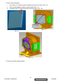
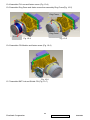
2. Optical Engine Assembly and Alignment Concerns
1. Assembly Lamp module:
1.1 Washer, Screw, Fin and Mesh Assembly
I. Assemble Washer and Screw to the HLD Lamp(Fig. 1-1)
II. Assemble “MESH” with Lamp holder .Mesh hooks HLD Lamp first (Fig. 1-2) and press it
assemble to the right position (Fig. 1-3).
III. Assemble “FIN” with Lamp holder and fasten screw (Fig. 1-4).
Fig. 1-1
Fig. 1-2
Fig. 1-3
Fig. 1-4
34
ViewSonic Corporation
Confidential - Do Not Copy
PJ513D-1
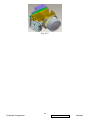
1.2 Front Glass Assembly.
i.
ii.
iii.
Front Glass UV coated surface (marked) must face to Lamp. (Fig. 1-6)
F/G must be placed on datum surfaces well. (Fig. 1-7)
To make sure F/G Clip hooked well with HLD lamp. (Fig. 1-8)
F/G datum
Fig. 1-7
Fig. 1-6
Fig. 1-8
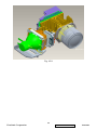
1.3 Lamp wire and Lamp Assembly.
35
ViewSonic Corporation
Confidential - Do Not Copy
PJ513D-1
Short wire
Long wire
Fig. 1-9
Fig. 1-10
36
ViewSonic Corporation
Confidential - Do Not Copy
PJ513D-1
i.
ii.
iii.
Insert Lamp into HLD Lamp and push Lamp forward to touch DTM Lamp of HLD
Lamp (Fig. 1-11)
To make sure that three datum contact with the lamp well(Fig. 1-12)
After assemble Lamp to HLD Lamp, Hook “Clip down Lamp” first then Hook “Clip UP
Lamp” on the HLD Lamp to fix Lamp last. (Fig. 1-13、1-14)
iv. Check assembly again and make sure the three datum contact with the lamp.
v. Assemble Plate Lamp to the HLD Lamp and fasten the screw(Fig. 1-15)
DTM of Lamp
Fig. 1-11
Fig. 1-12
Fig. 1-13
Fig. 1-14
37
ViewSonic Corporation
Confidential - Do Not Copy
PJ513D-1
Fig. 1-15
38
ViewSonic Corporation
Confidential - Do Not Copy
PJ513D-1
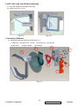
2. BKT LINK Lamp and CW Shield Assembly
2.1. Insert CW Shield and hook BKT LINK Lamp
2.2. Fasten screw (Fig. 2-1.2-2)
Fasten screw
Fig. 2-1
Fig. 2-2
3. Assembly CW Module
3.1 CW Module Assembly Sequence as blow (Fig. 3-1):
(1) BKT CW (2) Damper CW (3) CW
(6) M2 Screw
(7) Sensor Board
(4) Fixed screw (5) CVR CW
(8) M2 Screw
1
3
4
5
6
2
8
7
Fig. 3-1
39
ViewSonic Corporation
Confidential - Do Not Copy
PJ513D-1
Fig. 3-2
40
ViewSonic Corporation
Confidential - Do Not Copy
PJ513D-1
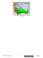
4. Assembly Baffle Stop AL
4.1. Assemble Baffle Stop AL on HSG DMD and fasten screw (Fig. 4-1)
Fig. 4-1
5. Assembly LP Module
5.1 LP must datum well with “BKT_LP” show as Figure 5-1
5.2 Referring to Figure 5-2,there must be visible clearance between “BKT_LP” and ”LP
opening” after assembly。
TOP Datum
Clearance
RIGHT Datum
Fig. 5-1
Fig.5-2
5.3 Glue “LP” and “BKT_LP” with “”UV5503 Glue” at two opening of “BKT_LP” show in Figure
5-3.
5.4 UV-5503 Glue curing process and concerns:
vi. The UV-glue must fill up the whole opening area (shown in Figure 5-3) to contact well
41
ViewSonic Corporation
Confidential - Do Not Copy
PJ513D-1
with LP surfaces and BKT_LP.
vii. Exposed to visible light at 350 ~ 420nm (at least 100mW/cm2) wavelength for 1
minute.
viii. After curing, the height of UV-glue should not exceed BKT_LP for more than 0.6mm
Glue 5503
Fig. 5-3
5.5 Assembly LP Module to HSG DMD
i. Assembly two Overfill adjustment screw (8F.1A752.8R0) to HSG DMD (Fig. 5-4).
** Adjustment criteria refer to item 5.6.
ii. Insert CLIP of BKT_LP into the hole
iii. Placed LP Module on LP datum and adjustment screw well, shown (Fig. 5-6).
iv. Assembly “Baffle LP” first ( Figure 5-7)and make sure it hooks HSG DMD well
~ Assembly Criteria was shown in Figure 5-7-2.
v. Assembly “Clip_LP” second (Fig. 4-8) and make sure it hooks HSG DMD well.
( Figure 5-9).
vi. Push two hook places to make sure that Baffle_LP touches “BKT_LP “well, don’t push
the middle place of “Baffle_LP”.
5.6 Overfill Adjustment @ LP Module
Overfill Adjustment Criteria:
i.
ii.
Pre-assembly 2 adjusting screws. Criteria shown as Figure 5-10.
Alignment Sequence:
a.
To adjust “Horizontal Adjustment Screw” firstly, then “Vertical Adjustment
Screw”.
b.
Refer to Figure 4-10.
For Overfill Re-adjustment:
1. Those 2 Adjustment Screws must be released closely to the “Pre-assembly”
positions first. (defined in 4.6-i )
42
ViewSonic Corporation
Confidential - Do Not Copy
PJ513D-1
2. Follow adjustment steps shown in Item 4.6-ii.
(1) Overfill Vertical
Adjustment Screw
CLIP of BKT LP
Fig.5-4
(1) Overfill Horizontal
Fig. 5-5
Overfill adjustment screw
LP DATUM
Fig. 5-6
43
ViewSonic Corporation
Confidential - Do Not Copy
PJ513D-1
Baffle_LP hooks HSG
DMD first
To ensure clip hooks
HSG DMD well.
BAFFLE LP
This area is not
allowed to be
pressed while
assembling Baffle
Fig. 5-7 (1)
Fig. 5-7(2)
Clip LP
Fig. 5-8
Fig. 5-9
44
ViewSonic Corporation
Confidential - Do Not Copy
PJ513D-1
Pre-assy this screw not over
the side surface.
(1) Overfill Horizontal
Adjustment Screw
(2) Overfill Vertical
Adjustment Screw
Pre-assy this screw not over
the bottom surface.
Fig. 5-10
6. Assembly HSG ILL Module
6.1 FM1 Assembly
I. FM1 must be placed on datum surfaces well and breach of FM1 must be face to inside
(Fig. 6-1)
II. Insert the” CLIP of FM1” into the hole on the HSG ILL and make sure ” CLIP of FM”
hook on the HSG ILL well (Fig. 6-2)
6.2 CM Assembly
III. Insert Clip CM Side and Clip CM Bottom first (Fig. 6-3,6-5)
IV. Assemble CM to HSG ILL and to make CM contact three datum on the HSG ILL
Well (Fig. 6-8)
V. Assemble “CLIP of TOP” to the HSG ILL (Fig. 6-9)
VI. To check and make sure “ CLIP of CM” hooks the HSG ILL very Well (Fig.
6-4, 6-6,6-10)
VII. Assemble Baffle Stop to HSG ILL and fasten screw (Fig. 6-10)
VIII. Paste Sponge tube AL on cannelure of HSG ILL(Fig. 6-11)
45
ViewSonic Corporation
Confidential - Do Not Copy
PJ513D-1
Breach of FM1
Fig. 6-1
Fig. 6-2
CLUP CM DOWN
Fig. 6-3
Fig. 6-4
46
ViewSonic Corporation
Confidential - Do Not Copy
PJ513D-1
DTM of CM
Fig. 6-5
Fig. 6-6
CLIP CM SIDE
Fig. 6-7
Fig. 6-8
CLIP CM TOP
Fig. 6-9
Fig. 6-10
47
ViewSonic Corporation
Confidential - Do Not Copy
PJ513D-1
Baffle Stop
Fig. 6-10
Sponge
Fig. 6-11
48
ViewSonic Corporation
Confidential - Do Not Copy
PJ513D-1
7. AL, HSG ILL and HSG DMD Assembly:
7.1 Placed “AL” on the HSG DMD .The “raised surface” of “AL” shall toward “DMD direction”
(Fig. 7-1)
7.2 Assemble” HSG ILL Module” to HSG DMD and cover over on “AL” (Fig. 7-2)
DMD Direction
AL
Fig. 7-1
Fig. 7-2
8. DMD and Chip B/D Module
8.1. Judge Chip B/D and DMD alignment keying first (Fig. 8-1, 8-2)
8.2. Alight keying and Assemble DMD to Chip B/D (Fig. 8-3)
8.3. Push DMD slightly and use screwdriver rotate button to lock DMD on Chip B/D (Fig. 8-4)
Alignment keying
Fig. 8-1
Fig. 8-2
49
ViewSonic Corporation
Confidential - Do Not Copy
PJ513D-1
Button
Fig. 8-3
Fig. 8-4
9. AL , HSG ILL and HSG DMD Assembly:
9.1 Placed “AL” on the HSG DMD .The “raised surface” of “AL” shall toward “DMD direction”
(Fig. 9-1)
9.2 Assemble” HSG ILL Module” to HSG DMD and cover over on “AL” (Fig. 9-2)
Fig. 9-1
Fig. 9-2
50
ViewSonic Corporation
Confidential - Do Not Copy
PJ513D-1
10. Assembly OP ENG
10.1 Assemble Baffle DMD to HSG DMD (Fig. 10-1)
10.2 Assemble Chip B/D Module to HSG DMD and fasten the screw(Fig. 10-2)
Fig. 10-1
Fig. 10-2
10.3 Fasten shoulder screw Sequence as blow (Fig. 10-3)
i.
ii.
iii.
Pre-fastening Sequence: [ 1 ] - [ 2 ] - [ 3 ] - [ 4 ]
Fastening Sequence [ 2 ] - [ 1 ] - [ 4 ] - [ 3 ]
Screw Torque must be confirmed to be 2.5 kg-cm.
1
3
4
2
Fig. 10-3
51
ViewSonic Corporation
Confidential - Do Not Copy
PJ513D-1
10.4 Assemble PL Lens and fasten screw (Fig. 10-4)
10.5 Assemble Ring Zoom and fasten screw then assembly Ring Focus(Fig. 10-5)
Ring Focus
Ring Zoom
Screw
Fig. 10-4
Fig. 10-5
10.6 Assemble CW Module and fasten screw (Fig. 10-6)
Fig. 10-6
10.7 Assemble BKT Link and Shield CW (Fig. 10-7)
52
ViewSonic Corporation
Confidential - Do Not Copy
PJ513D-1
Fig. 10-7
53
ViewSonic Corporation
Confidential - Do Not Copy
PJ513D-1
10.8-1 Assemble Thermal pad and Hest-sink
10.8-2 Fasten “Assy spring screw” Sequence as blow (Fig.10-8)
Pre-fastening Sequence: [ 1 ] - [ 2 ]
Fastening Sequence [ 2 ] - [ 1 ]
Screw Torque must be confirmed to be 6 kg-cm.
2
1
Fig. 10-8
10.9 Assemble Lamp Module and fasten screw (Fig. 10-9)
54
ViewSonic Corporation
Confidential - Do Not Copy
PJ513D-1
Fig. 10-9
55
ViewSonic Corporation
Confidential - Do Not Copy
PJ513D-1
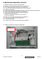
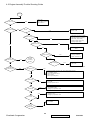
3. Mechanical Assembly Concern
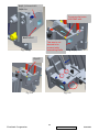
3.1. Ballast assembly and lamp wire alignment
3.2. Blower module assembly and blower wire alignment
3.3. OPT engine assembly and blower wire alignment
3.4. Power board assembly and power board wire alignment
3.5. Lamp box assembly
3.6. Power board shielding assembly and power board grounding wire alignment
3.7. Main board assembly and ballast wire alignment
3.8. Main board shielding assembly and wire alignment
a. Main board shielding assembly
b. C/W FPC, C/W sensor wire and blower wire alignment
c. Front IR wire alignment
3.9. Rear cover assembly and speaker wire alignment
3.10. Twin fans assembly and wire alignment.
3.11. IR board assembly
3.12. Upper case, inlet cover and outlet cover assembly
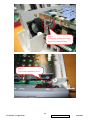
3.1. Ballast assembly and lamp wire alignment
To keep the wire
into the rib
56
ViewSonic Corporation
Confidential - Do Not Copy
PJ513D-1
To keep the wire
into the rib.
To keep the wire
into the rib.
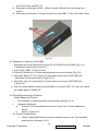
3.2. Blower module assembly and blower wire alignment
To keep the wire under
the blower
57
ViewSonic Corporation
Confidential - Do Not Copy
PJ513D-1
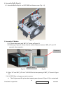
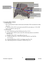
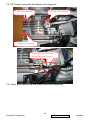
3.3. OPT engine assembly and blower wire alignment
2. Second screw constrain
1. First screw constrain
3. Third screw constrain
To keep the blower wire under
the heat sink of OPT engine.
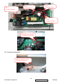
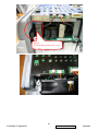
3.4. Power board assembly and power board wire alignment
58
ViewSonic Corporation
Confidential - Do Not Copy
PJ513D-1
Step 1
To lock this screw
Step 3
To plug in thermal
b k i
t
Step 2
To lock this screw.
Step 4
To plug in ballast
i
t
Put ballast wire into this
opening of power board
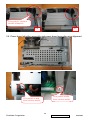
3.5. Lamp box assembly
To keep the hook of lower
case into the lamp box
59
ViewSonic Corporation
Confidential - Do Not Copy
PJ513D-1
To keep the FC’s mylar at
left side of lamp box
OK
NG
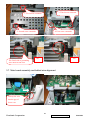
3.6. Power board shielding assembly and power board grounding wire alignment
To be put hole to hold
lower case boss and fix.
To be put hole to hold
lower case boss and fix.
60
ViewSonic Corporation
Confidential - Do Not Copy
PJ513D-1
3. Third screw constrain
1. First screw constrain
2. Second screw constrain
The fixed side of grounding
wire must be take care
4. Four screw constrain
OK
NG
3.7. Main board assembly and ballast wire alignment
To keep the wire
into the gap of
lower case
61
ViewSonic Corporation
Confidential - Do Not Copy
PJ513D-1
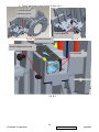
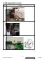
3.8. Main board shielding assembly and wire alignment
a. Main board shielding assembly
To take care, the main board shielding
must keep into the gap between lamp
box and power board shielding
5. Fifthly screw constrain
3. Third screw constrain
1. First screw constrain
2. Second screw constrain
4. Fourth screw constrain
62
ViewSonic Corporation
Confidential - Do Not Copy
PJ513D-1
b. C/W FC, C/W sensor wire & blower wire alignment
To keep the redundant
wire above lamp box
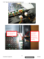
c. Front IR wire alignment
Step 1.
To keep the IR wire into
the saddle wire.
Step 2.
To plug in the connector.
63
ViewSonic Corporation
Confidential - Do Not Copy
PJ513D-1
Step 3.
To keep the IR wire under
the power board shielding
Step 3.
To keep the IR wire under
the
Step 4.
To keep the IR wire into
h fl
f OPT h i
64
ViewSonic Corporation
Confidential - Do Not Copy
PJ513D-1
C/W FPC
Front IR wire
Blower wire
C/W sensor wire
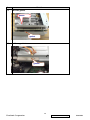
3.9. Rear cover assembly and speaker wire alignment
Step 1.
To plug in the connector
65
ViewSonic Corporation
Confidential - Do Not Copy
PJ513D-1
Step 2
To keep the speaker wire under
the power board shielding
Step 3.
To keep the redundant wire to
66
ViewSonic Corporation
Confidential - Do Not Copy
PJ513D-1
Step 4.
To check the speaker wire is not
i db
67
ViewSonic Corporation
Confidential - Do Not Copy
PJ513D-1
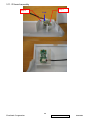
3.10. Twin fans assembly and wire alignment.
Fan wire must keep this
location. Don’t put wire
on top of the fan.
Do not plug in or
pull out the fan
connector by
holding the wire.
Do not pinch the
wire together when
assembling.
68
ViewSonic Corporation
Confidential - Do Not Copy
PJ513D-1
3.11. IR board assembly
Step 2
Step 1
Push
69
ViewSonic Corporation
Confidential - Do Not Copy
PJ513D-1
3.12. Upper case, inlet cover and outlet cover assembly
The rib of side cover must
keep into the constrain
gap of upper case.
OK
NG
70
ViewSonic Corporation
Confidential - Do Not Copy
PJ513D-1
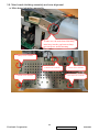
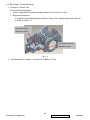
4. Power Assembly Concern
a. The wire from power to ballast -The connector near the core should be connected with the ballast.
71
ViewSonic Corporation
Confidential - Do Not Copy
PJ513D-1
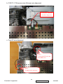
5. EMI Assembly Concern
Item
Solution
1.
Fix the cable at the binding core by this way
2.
Add one spring
3.
Add one spring
72
ViewSonic Corporation
Confidential - Do Not Copy
PJ513D-1
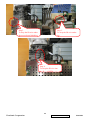
Item
4.
Solution
Add two gasket
gasket
gasket
5.
Add one gasket
gasket
73
ViewSonic Corporation
Confidential - Do Not Copy
PJ513D-1
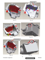
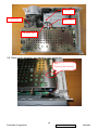
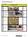
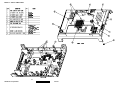
Disassembly/Assembly
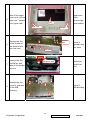
Disassembly SOP
PJ513D Dismantle SOP
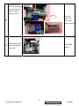
Step Description
Parts
cap lens
1
take off the cap
lens
2
disassembly the
screw*2, and take
off the lamp door,
disassembly the
screw*1 and lamp
wire, take off the
lamp module.
cap lens
Lamp wire
screw*3,
lamp door,
lamp wire,
lamp module
1
2
screw*4
1
3
3
disassembly the
screw*4
4
2
4
take off the upper
case module
upper case
module
upper case
74
ViewSonic Corporation
Confidential - Do Not Copy
PJ513D-1
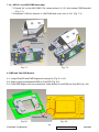
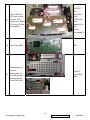
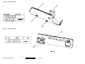
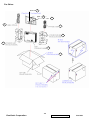
5
take off the upper
case mylar, left and
right case module
from upper case
mylar
right case
6
7
8
disassembly the
screw*4,take off
the Speaker wire
and rear case
left case
Speaker
wire
3
1
2
disassembly the
double fan, and
take off the double
fan wire
disassembly the
screw*5, and take
off the M/B
shielding
upper case
mylar,
left and right
case module
4
rear case
Double fan Wire
4
double fan,
double fan
wire
1
5
screw*5,
M/B shielding
2
3
75
ViewSonic Corporation
screw*4,
Speaker wire,
rear case
Confidential - Do Not Copy
PJ513D-1
Wire saddle 1
Wire saddle 2
9
take off the C/W
FPC wire, blower
fan wire, C/W
sensor wire, Ballast
5-Pin wire, IR wire,
wire saddle*2
C/W sensor
wire
C/W FPC
wire
IR wire
Blower fan
wire
Ballast 5-Pin
wire
C/W FPC
wire,
blower fan
wire,
C/W sensor
wire,
Ballast 5-Pin
wire,
IR wire,
wire saddle*2
10 take off the M/B
M/B
disassembly the
screw*4,
disassembly the
11
grounding screw*1
and take off the
Power B/D SHD
screw*5,
Power B/D
SHD
76
ViewSonic Corporation
Confidential - Do Not Copy
PJ513D-1
disassembly the
wire*2 and
12 screw*2, take off
the power BD and
ballast Mylar
wire*2
screw*2,
power BD,
ballast Mylar
1
disassembly the
screw*4, take off
13
the lamp box and
the blower fan
4
2
screw*4,
lamp box,
blower fan
3
disassembly the
screw*3, take off
14
the OPT eng and
IR wire.
1
2
screw*3,
OPT eng,
IR wire
3
15
take the Front case
module
Front case
module
77
ViewSonic Corporation
Confidential - Do Not Copy
PJ513D-1
take off the Front
case mylar, IR
Sensor and IR
16
Sensor wire
module from Front
case
IR Sensor
Front case
mylar,
IR Sensor,
IR Sensor wire
Mylar
IR Sensor wire
1
disassembly the
17 screw*3 and the
ballast BD, wire*3
take off the push
button and the
adjust foot,
18 disassembly the
screw*6 and clip*3,
the left is lower
case
2
screw*3,
ballast BD,
wire*3
3
Adjust foot
push button,
adjust foot,
screw*6,
clip*3,
lower case
Push button
take off the
sponge,
19 disassembly the
screw*2 and DMD
HSINK
sponge,
screw*2,
DMD HSINK
78
ViewSonic Corporation
Confidential - Do Not Copy
PJ513D-1
disassembly the
screw*2,take off
the CW shielding,
20
disassembly the
screw*1 and take
off the CW module
screw*3,
CW shielding,
CW module
CW module
Focus ring
21
Remove FOCUS
ring
FOCUS ring
disassembly the
22 screw*3, take off
the PL ass'y
screw*3,
PL ass'y
79
ViewSonic Corporation
Confidential - Do Not Copy
PJ513D-1
disassembly the
screw*4, and take
23 off the Chip BD
module , take off
the Baffle DMD
screw*4,
Chip BD,
Baffle DMD
rotate the screw,
take off the DMD
24
IC, take off the
Thermal PAD
DMD IC,
Thermal PAD
disassembly ILL
MODULE( screw*2
25
),sponge, ASPH
lens
ILL MODULE,
screw*2,
sponge,
ASPH lens
80
ViewSonic Corporation
Confidential - Do Not Copy
PJ513D-1
disassembly the
front clip and upper
clip, then take off
the LP module,
adjust screw*2
upper clip
26
front clip,
upper clip,
LP module,
adjust screw*2
disassembly HSG
27 baffle and screw*1
from HSG
HSG baffle,
screw*1
front clip
81
ViewSonic Corporation
Confidential - Do Not Copy
PJ513D-1
6. Troubleshooting Flow Chart
1. System Trouble Shooting Flow Chart
System Trouble Shooting Flow Chart
No
LED On?
Yes
If Power On, Lamp On?
No
1.
2.
3.
4.
5.
Check power code
Check lamp door.
Check Download SW.
Check DC Voltage 1.2V 1.8V 2.5V 3.3Von Main
board
Check power board and 14-pin power connector.
1.
2.
3.
4.
5.
6.
Check Main BD to Ballast signal wire.
Check thermal switch and wire
Check color wheel.
Check DC Voltage 12V on Main board
Check Ballast.
Check Power Board.
1.
2.
3.
Check Input Cable
Check OSD Source set up
Check Main board
1.
2.
3.
4.
5.
Check OSD Lamp Hours
Check Lamp Door
Check Lamp still light or not?
Check Fan still spin or not?
Check Thermal status
1.
2.
3.
4.
Check Remote module battery
Check Remote module
Check IR Receiver on Main board
Check IR Receiver on Input board
1.
2.
3.
Check DMD Chip
Check DMD Chip board
Check Main board
Yes
Yes
No Signal?
No
Yes
Power Auto Turn Off
No
Yes
IR Remote Control NG?
No
Yes
Pixel Fail?
A
82
ViewSonic Corporation
Confidential - Do Not Copy
PJ513D-1
A
No
Image NG?
(Raindrops)
Yes
1.
2.
3.
4.
Check color wheel and Sensor board
Check DMD Chip and holder
Check Main BD XDRAM
Check Main BD DDP2230
Yes
1.
2.
3.
4.
Check Main board
Check color wheel and sensor board
Check DMD Chip board
Check DMD Chip and socket
Yes
1.
2.
3.
Check color wheel and sensor board
Check Main board
Check DMD Chip board
1.
2.
Check Main board
Check DMD Chip board
Yes
1.
2.
3.
Check color wheel
Check sensor board color index signal
Check main board
Yes
1.
2.
3.
Check DMD Chip holder
Check DMD Chip board
Check Main board
1.
Check Main BD output to DMD Chip
BD Resistance soldering
Check Main BD output to DMD Chip
BD capacitor soldering
No
Image NG?
(Blank)
No
Image NG?
(Screen flashing)
No
Image NG?
(Screen Dim-mish)
Yes
No
Image NG?
(Freezing)
No
Image NG?
(Missing column bar)
No
Image NG?
(Screen overlap)
2.
Yes
83
ViewSonic Corporation
Confidential - Do Not Copy
PJ513D-1
2. Error Message
Power Temp Lamp Status
Note
O
-
-
Stand-by
G
-
-
Powering up
G
-
-
Normal operation
O
-
-
Normal power-down cooling
O
-
-
First Lamp-Lit error cooling
Lamp Error Messages
O
-
R
Second Lamp-Lit error
-
-
R
Lamp error in normal operation
Thermal Error Messages
-
R
-
Fan 1 error (the actual fan speed is ±20% outside the
desired speed.)
Lamp Fan
-
R
R
Fan 2 error (the actual fan speed is ±20% outside the
desired speed.)
Ballast Fan
-
R
G
Fan 3 error (the actual fan speed is ±20% outside the
desired speed.)
Blower Fan
R
R
R
Thermal Sensor 1 open error (the remote diode has an
open-circuit condition.)
DMD sensor
R
R
G
Thermal Sensor 2 open error (the remote diode has an
open-circuit condition.)
G
R
R
Thermal Sensor 1 short error (the remote diode has an
short-circuit condition.)
G
R
G
Thermal Sensor 2 short error (the remote diode has an
short-circuit condition.)
O
R
R
Temperature 1 error (over limited temperature)
O
R
G
Temperature 2 error (over limited temperature)
-
G
R
Fan IC #1 I2C Connection error
DMD sensor
GMT 793
84
ViewSonic Corporation
DMD sensor
Confidential - Do Not Copy
PJ513D-1
3. Power Trouble Shooting Guide
Power BD Check.
Fuse Broken ?
Proceed to “check
DC-DC OUTPUT"
No
Yes
Proceed to "Primary
Circuit Check".
No DC-DC
Output.
B+=385VDC ?
No
Proceed to " Primary
Circuit Check"
Yes
TOPSwitch
Broken ?
No
Lacks of some
componets around
TOPSitch ?
Yes
Yes
Replace new
TOPSwitch
solder them.
No
85
ViewSonic Corporation
Confidential - Do Not Copy
Check Trace.
PJ513D-1
Check primary
circuit.
Fuse Broken ?
Proceed to "Check
IC601".
No
Yes
Check Q601
damages ?
Check BD601
damages ?
No
Yes
Yes
PinD & PinS of
Q601 are shorted.
Replace new
MOSFET.
Inside diodes of
BD601 are
shorted. Replace
new bridge diode.
No
Proceed to "Check
IC601".
Check IC601.
Check Pin8 if
shorted to GND.
Output Pin shorted to
GND ? (Pin8)
No
Check 15VPFC
Votage.
Yes
Replace with new
IC L6561D and
D611, D612, and
D613
86
ViewSonic Corporation
Confidential - Do Not Copy
PJ513D-1
4. Optical & Optical Engine Trouble Shooting Guide
4-1 Optical Trouble Shooting Guide
No.
Item
Trouble Shooting Guide
1
Brightness
1. Change lamp
2
Uniformity
1. Change lamp
FOFO Contrast
1.
2.
3.
4.
5.
4
ANSI Contrast
1. Clean PL
2. Clean DMD
3. Change PL
5
Color
1. Check color wheel delay
2. Check CW 50% point. Replace CW if necessary
6
Color Uniformity
1. Change lamp
Blue Edge
1. Refer to Item#2-1 (attached below)
2. Change CM
3. Change SUB HSG
8
Blue/Purple Border
1. Refer to Item#2-1(attached below)
2. Change CM
3. Change SUB HSG
9
Focus
1. Change Projection Lens
2. Check PL datum and DMD parallel
10
Dust
Clean DMD
11
Horizontal/Vertical
Strips
1.
2.
3.
4.
5.
12
Pixel Fail
Change new DMD
3
7
Check ADC calibration
Check user’s menu brightness & contrast are default
Clean DMD
Clean PL
Check ILL stop assy
Check connector between chipBD and MainBD
Re-install DMD with chipBD
Check if any pin of C-Spring is missing, damaged or dirty
Change new ChipBD/C-Spring
Change new DMD
87
ViewSonic Corporation
Confidential - Do Not Copy
PJ513D-1
4-2 Engine Assembly Trouble Shooting Guide
S ta rt
P ower O n
1 .c h k C W
2 .c h k D M D C h ip /b
3 .c h k M a in /b
NG
OK
Im a g e Q u a lity
NG
D ust
1 .c le a n D M D c h ip
2 .c le a n C /M
Yes
No
1 .c h k le n s h o u s in g / D M D
h o u s in g A s s e m b ly
2 .c h k lig h t p ip e a s s e m b ly
3 .c h k C /M a s s e m b ly
4 ,c h a n g e lig h t p ip e c lip
5 .c h a n g e lig h t p ip e
B lu e E d g e
Yes
No
Focus N G
OK
Y es
c h a n g e p ro je c tio n
le n s
No
P ix e l F a ilu re
EE
P e rfo rm a n c e
NG
S y s te m
T ro u b le
s h o o tin g
G u id e
No
lig h t le a k a g e
OK
O p tic a l
P e rfo rm a n c e
1 .c h a n g e D M D
2 .c h a n g e D M D /b
3 .c le a n e la s to m e r
Y es
Yes
1 .c h k D M D b a ffle
2 .c h k C /M
Or check DMD chip socket
NG
B rig h tn e s s
Y es
1 .R e s e t F a c to ry m o d e , c h k D C o ffs e t/G a in s e tu p
2 .c h k D M D c h ip /b
3 .c le a n p ro je c tio n le n s
4 .c le a n C /M
5 .c le a n o p tic a l p a rts
No
U n ifo rm ity
1 .c h k C /M
2 .c h k p ro je c tio n le n s
Y es
No
1 .R e s e t F a c to ry m o d e , c h k D C o ffs e t/G a in s e tu p
2 .c h k D M D b a ffle
3 .c h a n g e p ro je c tio n le n s
Y es
C o n tra s t
No
1 .R e s e t F a c to ry m o d e , c h k C W d e la y
2 .c h a n g e C W
3 .c h a n g e p ro je c tio n le n s
Y es
C o lo r
1 .c h k C /M
2 .c h k D M D
No
C o lo r
U n ifo rm ity
Y es
88
ViewSonic Corporation
Confidential - Do Not Copy
PJ513D-1
4-3 “Blue Edge” Trouble Shooting:
I. Re-adjust “Overfill” first.
For Overfill Re-adjustment:
i. Those 2 Adjustment Screws must be released for around 2 mm first.
ii. Alignment Sequence:
a.To adjust “Horizontal Adjustment Screw” firstly, then “Vertical Adjustment Screw¡¨.
b. Refer to Figure 1-1..
(2) Overfill Vertical
Adjustment Screw
(1) Overfill Horizontal
Adjustment Screw
Fig. 1-1
II. Re-assemble LP module—include LP, LP Baffle, LP clip.
89
ViewSonic Corporation
Confidential - Do Not Copy
PJ513D-1
7. Block Diagram
Hardware Architecture
The Projector consists of the Source board, Main board, Keypad board, Fan board, EMI board,
PFC board, Ballast board, Door interlock switch, Color wheel index sensor board, and the
Thermal break sensor board. Please see Figure 1.
Source Board consists of audio phone jack, video RCA jack, S-video mini-DIN head, and USB
head. Main Board consists of RGB A/D conversion, Video decoder, DLP ASIC, Flash and RAM,
Motor driver, DMD Reset driver DAD2000, and IR receiver. Keypad Board consists of 8 keypads
and 3 twice-color LEDs. Fan Board consists of DC/DC converter, Thermal Break circuit, Blower
Fan driver circuit, Rear Fan driver circuit, and the temperature sensing circuit. Power supply
circuit consists of AC line EMI filter, Power Factor Correction circuit. Ballast Board consists of
Lamp synchronization circuit, Lamp lit feedback circuit, and Lamp power control circuit.
Hardware Architecture
Keypad Circuit
Main Operation Circuit
(DLP Image Processor
DDP2230)
(Video decoder TVP5147)
(DMD Reset driver DAD2000)
(A/D 9883)
(RAMBUS XDRAM)
Thermal break
sensor Circuit
Fan Driver
Circuit
Input Source
Circuit
From AC
socket
Ballast
Module
CW
Lamp
Index
Door
sensor
switch
Door
interlock
switch
EMI
PFC Circuit
Filter
90
ViewSonic Corporation
To Lamp
Confidential - Do Not Copy
PJ513D-1
8. Schematic Diagrams
6,7,9,11,17
6,7,9,11,17
PC-RIN
PC-GIN
PC-BIN
HSYNC_I
VSYNC_I
SDA
SCL
PC-RIN
PC-GIN
PC-BIN
PC-RIN
PC-GIN
PC-BIN
HSYNC _I
VSYNC_I
HSYNC_I
VSYNC_I
P3P3V
P5V
P3P3V
P5V
P3P3V
GRE[7:0]
GRE[7:0]
GGE[7:0]
GGE[7:0]
GBE[7:0]
GBE[7:0]
AD_CLK
AD_HS
AD_VS
AD_CLK
AD_HS
AD_VS
P5V
V33
P3P3V
AD_SOG
AD_CLAMP
AD_COAST
AD_SOG
AD_CLAMP
AD_COAST
SDA
SCL
AD_SOG
AD_CLAMP
AD_COAST
GRE[7:0]
GGE[7:0]
GBE[7:0]
AD_CLK
AD_HS
AD_VS
POSENSE
POSENSE
POSENSE
MTR_ARSTZ
PMD_INTZ
SSP0CSZ2
PWRGOOD
V33
GND
SSP0_CLK
05_ADC
05_ADC
P5V
HSYNC _I
VSYNC_I
SSP0_RXD
SSP0_TXD
HSYNC_I
VSYNC_I
PWR_DOWN
POSENSE
MTR_ARSTZ
PMD_INTZ
SSP0_CSZ2
PWRGOOD
A1P2V
P1P2V
A1P2V
P1P2V
A1P8V
P1P8V
A1P8V
P1P8V
P2P5V
P2P5V
P3P3V
P3P3V
P5V
P5V
P12V
P12V
SSP0_CLK
SSP0_RXD
SSP0_TXD
GND
11_PMD1000
11_PMD1000
GND
01_D-SUB_I/O
01_D-SUB_I/O
SSP0_CLK
P1P8V
P1P8V
VD_CLK
P2P5V
P2P5V
VD_YUV[9:0]
P3P3V
P3P3V
VD_CLK
VD_YUV[9:0]
VD_CLK
VD_YUV[9:0]
SDA
SCL
SDA
SCL
6,9,14,15 EXT_ARSTZ
GND
A1P2V
P1P2V
A1P2VIO
POSENSE
MTR_ARSTZ
PMD_INTZ
SSP0_CSZ2
PWRGOOD
V33
V33
CVBS
POSENSE
MTR_ARSTZ
PMD_INTZ
SSP0_CSZ2
PWRGOOD
PWRGOOD
EXT_ARSTZ
CVBS
SSP0_CLK
SSP0_CLK
SSP0_RXD
SSP0_TXD
SSP0_CSZ0
EXT_ARSTZ
SSP0_RXD
SSP0_TXD
SSP0_CSZ0
EXT_ARSTZ
SSP0_RXD
SSP0_TXD
SSP0_CSZ0
EXT_ARSTZ
6,9,14,15 EXT_ARSTZ
CVBS
CHROMA
LUMA
PWRGOOD
CHROMA
LUMA
AUDIO_MUT
AUDIO_VOL
AUDIO_SW
P1P8V
P3P3V
P3P3V
GND
SSP0_CLK
P3P3V
P3P3VS
P5V
P3P3V
P3P3VS
P5V
GND
USB_D+
USB_DUART0_CTSZ
UART0_RXD
UART0_RTSZ
UART0_TXD
AUDIO_MUT
AUDIO_VOL
AUDIO_SW
AUDIO_MUT
AUDIO_VOL
AUDIO_SW
VCC2
VCC2
P3P3V
P3P3V
IRRCVR
LAMPLIT
LAMP_RXD
LAMPEN
P3P3VS
6,7,9,11,17
6,7,9,11,17
12_DAD1000
12_DAD1000
SSP0_CSZ1
EXT_ARSTZ
SSP0_CSZ1
PWM_AUDIO1
PWM_AUDIO2
PWM_AUDIO3
USB_D+
USB_D-
USB_D+
USB_D-
UART0_CTSZ
UART0_RXD
UART0_RTSZ
UART0_TXD
UART0_CTSZ
UART0_RXD
UART0_RTSZ
UART0_TXD
P3P3VS
P5VS
P5V
P5VS
P5V
P12V
P12V
FAN2_B
FAN2_E
PWR_DOWN
PWR_DOWN
IRRC VR
IRRC VR
LAMPLIT
LAMP_RXD
LAMPEN
LAMPLIT
LAMP_RXD
LAMPEN
FAN_SW
FAN_SW
SDA
SCL
SDA
SCL
FAN2_B
FAN2_E
P3P3V
FAN2_B
FAN2_E
P5V
P12V
GND
MBRST[15:0]
VCC2
UART0_CTSZ
UART0_RXD
UART0_RTSZ
UART0_TXD
XDR_RQ_CTMP
XDR_RQ_CTMN
XDR_RQ_CTMP
XDR_RQ_CTMN
SDA
SCL
SDA
SCL
6,7,9,11,17
6,7,9,11,17
6,7,9,11,17
6,7,9,11,17
SDA
SCL
OCLKA
PWR_DOWN
P3P3V
GND
SDA
SCL
OCLKA
A1P8V
A1P8V
P2P5V
P2P5V
P3P3V
P3P3V
XDR_RQ_CTMPA1P2VIO
XDR_RQ_CTMN
P1P8V
A1P2VIO
P1P8V
GND
10_XDRAM
10_XDRAM
GND
09_CLOCK
09_CLOCK
IRRCVR
LAMPLIT
LAMP_RXD
LAMPEN
FAN_SW
P3P3V
EXT_ARSTZ
SSP0_CSZ1
13_DMD_INTERFACE
13_DMD_INTERFACE
USB_D+
USB_D-
OCLKA
CW_PWM
CWINDEXA
CW_PWM
CWINDEXA
OCLKA
CW_PWM
CWINDEXA
P12V
P12V
P5V
P5V
P3P3V
P3P3V
P3P3V
GND
P5V
P3P3VS
P3P3V
P12V
GND
P5VS
P5V
15_FAN
15_FAN
03_POWER
03_POWER
VCC2
P12V
SSP0_CSZ1
02_INPUT
02_INPUT
PWR_DOWN
MBRST[15:0]
MBRST[15:0]
SSP0_RXD
SSP0_TXD
SSP0_CSZ0
EXT_ARSTZ
GND
PWM_AUDIO1
PWM_AUDIO2
PWM_AUDIO3
PWM_AUDIO1
PWM_AUDIO2
PWM_AUDIO3
A1P2V
P1P2V
A1P2VIO
P1P8V
P12V
04_DECODER
04_DECODER
SSP0_RXD
SSP0_TXD
08_DDP2230_PWR_DEBUG
08_DDP2230_PWR_DEBUG
SSP0_CLK
CHROMA
LUMA
P3P3V
06_MEMORY_IN
06_MEMORY_IN
GND
6,7,9,11,17
6,7,9,11,17
P3P3V
SSP0_CLK
SSP0_RXD
SSP0_TXD
P3P3VS
P3P3V
14_CWMOTOR
14_CWMOTOR
P5VS
P5V
GND
07_DDP2230_ARM_CONTROL
07_DDP2230_ARM_CONTROL
ViewSonic Corporation
Model
Title
ViewSonic Corporation
Date
91
Confidential - Do Not Copy
PJ513D-1
MAIN BOARD
Rev:
P5V
K
K
4,5,6,7,9,13,16,17 P5V
DN2
J
PC-RIN_B
J
BAV99
D1
K
A
BAV99
PC-GIN_B
LL4148
A
PC-BIN_B
A
A
BAV99
TP10
13
14
15
TP8
A
D4
A
D5
P5V
PC-RIN_B
LC1
Z80
PC-RIN
PC-RIN
7
PC-GIN_B
LC2
Z80
PC-GIN
PC-GIN
7
PC-BIN_B
LC3
Z80
PC-BIN
PC-BIN
7
K
LL4148
K
LL4148
DDCP5V
G2
PC_VSYNC
PC _HSYNC
GSDA
PC_VSYNC
PC_HSYNC
GSDA
PC_VSYNC
D10
A
TZMC6V2
UB1
16
RB1
GOUT
15
RB2
BOUT
14
RB3
REF
VCC
13
5
VEE
EN
12
6
GND
VCC
11
7
VEEOUT
PD
10
PC-GIN_B
2
PC-BIN_B
3
BIN
4
CB10
0.1U K
10
CB2
8
0.1U K
RIN
GIN
DGND
U1
4
R3
1K J
VSYNC_I
7,8
HSYNC_I
7,8
R4
2K J
74AHCT1G14GV
1
A0
VCC
8
CA1
2
A1
WP
7
0.1U K
3
A2
SCL
6
4
GND
SDA
5
DDCP5V
DDCP5V
P5V
R5
4.7K J
R6
4.7K J
R7
4.7K J
GSCL
GSDA
PC_HSYNC
PC _HSYNC R8
47 J
CH1
150P J
C2
0.1U K
U3
2
4
R9
1K J
R10
2K J
74AHCT1G14GV
75 J
ROUT
1
4,5,6,7,9,13,16,17
C1
0.1U K
U2
AT24C02N-10SU-1.8
PC-RIN_B
47 J
R1
4.7K J
2
CV1
470P K
RGB D-sub input ciriuit
RB4
PC_VSYNC R2
GSCL
K
K
D9
A
TZMC6V2
A
TZMC6V2
D8
A
TZMC6V2
A
TZMC6V2
2,13,14,15,16,17 GND
K
K
K
GSCL
D7
P5V
DDCP5V
2K20072A15
D6
P5V
5
TP9
TP5
TP7
3
1
12
A
LL4148
DVCC
75 J
75 J
RGBO_R
RGBO_G
P3P3V
RGBO_B
P3P3V
CB1
P3P3V
0.1U K
C3
0.1U K
U4
5
TP6
RED-GND0
PC-RIN-B
GREEN-GND0
PC-GIN-B
BLUE-GND0
PC-BIN-B
PC-5VIN0
A
LL4148
4
CB3
9
0.1U K
ISL59837IAZ-T13
R11
47 J
2
PWR_DOWN
PW R_DOWN 9
74AHC1G14GV
GND
4,5,6,7,8,9,10,11,12,13,14,15,16,17
1
3
6
1
7
2
8
3
9
4
10
5
11
K
TP3
J1
TP4
D3
TP1
G1
TP2
K
D2
5
J
3
1
K
DN1
DN3
P5V
P5V
4,5,6,7,9,13,16,17
R12
2K J
C
PWR_DOWN_A
14
H SYNC_O
13
270 J
5
10
4
9
3
8
2
7
1
6
UB3
74HCT1G125GW
12
K
P5V
DB5
G1
CB5
0.1U K
5
PWR_DOWN_A
1
11
JB1
PC _HSYNC
RB8
47 J
2
4
RB9
K
PC_HSYNC
A
TZMC6V2
270 J
DB4
TPB1
TPB4
TPB5
RGBO_B
TPB6
RGBO_G
RGBO_R
P5V
DB1
J
BAV99
DB2
J
BAV99
DB3
J
BAV99
P5V
RGBO_R
4,5,6,7,9,13,16,17
D11
LL4148
A
A
A
A
TZMC6V2
A
3
ViewSonic Corporation
1.2K
RGBO_G
P5V
RB22
UB4
74HCT1G125GW
RGBO_B
K
15
VSYNC_O
K
RB7
E
G2
TPB3
4.7K J
RB5
K
4
2K20072015
RB21
1.2K TPB2
B
K
2
47 J
QC1
2N3904S
3
PC_VSYNC
PC_VSYNC
RB6
CB4
0.1U K
5
1
P5V
RGB D-sub output ciriuit
92
Confidential - Do Not Copy
PJ513D-1
DN4
P3P3V
TP15
U6
4
AUDIO
AUDIO_A
2
L2
Z42
CHROMA
4
CHROMA
9
6
AUDIO_SW
S1
S2
1
IN
TP16
ADG779
2
MODE
3
SVR
4
IN
OUT+
8
GND
7
Vp
6
OUT-
5
SPEAK+
P5V
C4
CC4
CC5
CC12 CC13
0.1U K 22U M 22U M 22U M 22U M
SPEAK-
RA1
SPEAK-
OPEN
J2
G1
1
2
G2
3,5,6,7,9,13,16,17
RC8
5.9K F
SPEAK+
SPEAK-
470
470
C
VOL
2KD2094102
9
AUDIO_VOL
RC9
1
K K
3,5,6,7,8,9,10,11,12,13,14,15,16,17
AUDIO_MUT
RC10
RC11
1K J
QC4
2N3904S
B
ZD8
TZMC6V2
A
Video input
RB10
1K J
RC12
1K J
A
ZD6
TZMC6V2
9
B
220 J
MUT
QC3
2N3904S
C
TP18
TZMC6V2
ZD7
K K
TZMC6V2
ZD5
QC2
2N3904S
B
220 J
RC13
150
C
BAV99
A
RC7
RC6
5.9K F
3,5,6,7,9,13,16,17 P5V
C
6
RC5
QC5
2N3904S
B
E
CVBS
P5V
TP11
TP12
TP13
E
CVBS
A
Z42
P5V
GND
Z42
RC14
1K J
RC15
150
E
BAV99
A
L3
J
DN6
K
SPEAK+
LC4
TDA8551T
P5V
COMPOSIT1
2
UP/DOWN
A
DN5
2
22U M
CC3
0.33U Z
RC4
4.7K J
TP17
1
CC2
22
RC3
5
1
E
K
P5V
P5V
U5
CC11 22U M
Dout
6
CC1
0.1U K
22
2
Z42
G2
MUTRC2
MUT
VDD
1
6
GND
L1
LUMA
3
G5
C
LUMA
3
G5
G3
.
2B10190051
470
J
G2
J4
RC1
J
Y
.
G3
VOL
VOL
G4
G1
2B14016041
BAV99
A
K
P5V
G4
G1
TP14
J3
Audio circuit
TP29TP30
USB_DUSB_D+
TPC1
TPC2
J5
P3P3V
1
2
TPC3 LC5
Z80
3
LC6
Z80
TP34
AUDIO
CC6
0.1U K
CC7
CC8
0.1U K
47P J
50V
A
2B10254071
AUDIO
RA2
RA3
OPEN 4.7K J
TZMC6V2
ZD3
AUDIO_A
CA2
PWM_AUDIO1
0.1U K
R186 0 J
RA5 PWM_AUDIO2
OPEN
R187 0 J
ZD4
TZMC6V2
PWM_AUDIO1 9
PWM_AUDIO2 9
PWM_AUDIO3 9
A
RA7
OPEN
Audio input terminal
TP23
V+
6
7
K
J
2
TP178
LC10
Z80
CTSZ_A
UC1
BAV99
A
A
3
V+
G1
G3
C1_A
232VRX.DL
3
5,9
P3P3VS
1
5
1
RTSZ_A 5
G1
G3
4
Z80
G2
2
LC9
G2
4
TP177
CTSZ
V+
J
BAV99
6
8
7
J7
BAV99
232V-
RTSZ
DN8
P3P3VS
A
BAV99
A
DN7
J
8
J
DN14
K
K
K
TP24
DN13
RX.DL 232VRTSZ
2B14015001 TP25
C2_A
CR2
0.1U K
C1_B
CR3
0.1U K
C2_B
232VCR4
CTSZ
CR5
RTSZ
CTSZ
1
2
3
4
5
6
7
8
C1+
V+
C1C2+
C2VT2OUT
R2IN
VCC
GND
T1OUT
R1IN
R1OUT
T1IN
T2IN
R2OUT
16
15
14
13
12
11
10
9
CR1
10U Z
TX.DL
RX.DL
TX.DL
RX.DL
UART0_RXD 9
UART0_TXD 9
UART0_RTSZ 9
UART0_CTSZ 9
ICL3232ECBNZ
RX.DL_A
LC7
Z80
TX.DL_A
LC8
Z80
0.1U K 0.1U K
TX.DL
CC9
100P K
TX.DL
CC10
100P K
3,5,6,7,8,9,10,11,12,13,14,15,16,17 GND
ViewSonic Corporation
RS232 circuit
93
Confidential - Do Not Copy
PJ513D-1
3,6,7,8,9,10,11,1
RA6
1.8K
PWM_AUDIO3
ZD2
TZMC6V2
A
RA4
4.7K J
P3P3V
AUDIO_A
TZMC6V2
ZD1
K K
A
A
USB input
9
9
D13
TZMC6V2
D12
2BC0010031
USB_DUSB_D+
K
K
VCC
DATADATA+
GND
GND
A
1
2
3
4
5
K K
J9
TZMC6V2
G2
CASE
CASE
G1
These parts of this portion should be connected closely.
FAN2_E
17
FAN2_B
P12V
TP45
L14
13,14,16,17 P12V
C172
4.7U M
C173
22U 25V
TP47
TP179P12V_IN
TP180
Z30
Z30
Z30
L15
C171
0.1U Z
17
L16
L17
L18
L19
J10
1
3
5
TP181 7
Z30 TP182 9
Z30
11
Z30
13
1
3
5
7
9
11
13
TP46
TP48
2
4
6
8
10
12
14
2
4
6
8
10
12
14
GND
TP183
R203
PWR_DOWN 9
2K71072207
TP49
3,4,6,7,8,9,10,11,12,13,14,15,16,17
R184
TP50
P5VS
0
1M
C175
C174
22U 25V
C176
4.7U M
0.1U Z
POWER FROM DC/DC BOARD
3,4,6,7,9,13,16,17
P5VS
9
L4
G2
5
4
3
2
1
G1
G2
5
4
3
2
1
G1
TP19
TP20
TP21
TP22
3
P5VS
VIN
Z120
C177
R14
100
R15
TP80
270 J
LAMPLIT
2
OUT
4
P3P3VS
G960T63UF
C178
100U 16V
<Spec>
4,9
C179
+
10U Z
9
C
2KL2021005
0.1U Z
LAMP_RXD 9
VOUT
1
J6
P3P3VS
U17
1
P5V
2
10K J
GND
P5V
R13
Q1
B
RA8
2K
LAMPEN
9
E
2N3904S
3,4,6,7,8,9,10,11,12,13,14,15,16,17 GND
Lamp circuit
3.3V POWER
P5VS
P5VS
R16
10K J
TP26
J8
TP27
G1
1
2
3
G2
G1
1
2
3
G2
TP28
L5
P3P3VS
Z120
2KL2021003
5
U8
TSOP14838
I R1
U7
1
4
VCC
GND
VOUT
R18
IR circuit
ViewSonic Corporation
94
Confidential - Do Not Copy
PJ513D-1
TP32
IRV CC
100 J
C5
0.1U K
C6
4.7U Z
R17
10K J
3
2
1
TP31
P5VS
2
I R2
3
P5VS
R19
510 J
TP33
74AHC1G08GW
IRRCVR
9
P1P8V
V33_A
V33
V33
7
C16
0.1U K
SCL
SDA
SCL
SDA
EXT_ARSTZ
EXT_ARSTZ
R22
10K J
TP35
TP36
TP37
TP38
R24
R25
R26
C18
27P J
Y1
RB11
100K
7
8
9
VI_2_A
VI_2_B
VI_2_C
16
17
18
VI_3_A
VI_3_B
VI_3_C
23
VI_4_A
28
29
SCL
SDA
33
34
35
36
37
PWDN
RESETB
GPIO
AVID/GPIO
GLCO/I2CA
71
72
73
FID/GPIO
HS/CS/GPIO
VS/VBLK/GPIO
74
75
14.31818MHZ
4.7K J10K J 2.2K
39
49
62
38
48
61
IOGND39
IOGND49
IOGND62
IOVDD38
IOVDD48
IOVDD61
TVP5147PFP
C_0/GPIO0
C_1/GPIO1
C_2/GPIO2
C_3/GPIO3
C_4/GPIO4
C_5/GPIO5
C_6/GPIO6
C_7/GPIO7
C_8/GPIO8
C_9/GPIO9
70
69
66
65
64
63
60
59
58
57
DATACLK
INTREQ
77
76
12
13
C19
27P J
3,4,5,7,8,9,10,11,12,13,14,15,16,17 GND
XTAL1
XTAL2
CH1_A33VDD
CH2_A33VDD
CH1_A33GND
CH2_A33GND
AGND
0.1U K
VI_1_A
VI_1_B
VI_1_C
NC14
NC15
NC19
NC20
NC21
NC22
P1P8V
V33_A
L7
Z120
V33
C20
0.1U K
VD_YUV0
VD_YUV1
VD_YUV2
VD_YUV3
VD_YUV4
VD_YUV5
VD_YUV6
VD_YUV7
VD_YUV8
VD_YUV9
R20
R21
Z120
V33
V33_A
C32
0.1U K
C33
0.1U K
C34
0.1U K
C35
0.1U K
C36
0.1U K
C37
0.1U K
C38
0.1U K
4.7K J
4.7K J
Analog VDD 3.3V
40 VCLK_A
30
14
15
19
20
21
22
R23
47 J
C17
10P J
VCLK
VD_CLK
8
P1P8V
P2P5V
V33
P2P5V
11,13
U10
1
C22
10U Z
VIN
C30
0.1U K
16V
P1P8V
AME8815AEGT180Z
VOUT 3
GND
TAB
9
C13
80
1
2
54
53
52
51
50
47
46
45
44
43
L6
C21
22U K
2
G1
9
7,9,11,17
CVBS_I
0.1U K
C11
C10
0.1U K
Cb_I_A
CHROMA_A
0.1U K
C9
Y_I_A
LUMA_A
0.1U K
C12
Cr_I_A
0.1U K
0.1U K C14
C15
CVBS_A
P3P3V
3,7,8,9,10,11,13,14,15,16,17 P3P3V
Y0
Y1
Y2
Y3
Y4
Y5
Y6
Y7
Y8
Y9
DVDD41
DVDD55
DVDD67
DVDD31
DGND27
DGND32
DGND42
DGND56
DGND68
CVBS_I
LUMA_I
C7
0.1U K
0.1U K
C8
VD_YUV[9:0] 8
41
55
67
31
27
32
42
56
68
LUMA_I
CHROMA_I
PLL_A18GND
PLL_A18VDD
A18VDD_REF
A18GND_REF
CHROMA_I
CH1_A18GND
CH2_A18GND
A18GND
CH1_A18VDD
CH2_A18VDD
A18VDD
D
4
5
3
6
26
79
10
24
78
11
25
VD_YUV[9:0]
C23
0.1U K
C24
0.22U K
C25
0.1U K
VTERM
P1P8V
P1P8V
C39
0.1U K
C43
C44
L9
CVBS
5.6P C
C45
1.8U K
L10
CVBS
CVBS_I
C46
220P J
C47
220P J
4 CVBS_I LUMA
L11
LUMA_I
C48
220P J
R27
75 J
P1P8V
1.8U K
C49
220P J
4
LUMA_I
CHROMA
1.8U K
CHROMA
CHROMA_I
C50
220P J
R28
75 J
C41
0.1U K
C42
0.1U K
5.6P C
5.6P C
LUMA
C40
0.1U K
C51
220P J
R29
75 J
CHROMA_I
C26
22U K
VTERM
L8
Z120
C27
0.1U K
C31
C28
0.1U K
0.1U K
2.5V TO 1.8V
ViewSonic Corporation
95
Confidential - Do Not Copy
PJ513D-1
10,12,13
C29
0.1U K
PVDD
C52
OPEN
C53
OPEN
R37
3
SOGIN
PC-GIN
1.5K
R30
OPEN
SOGIN
C69
10P J
V33
L12
AVDD
6
GVMID
3
3
8
8
VSYNC_I
HSYNC _I
AD_COAST
AD_CLAMP
VSYNC_I
HSYNC_I
AD_COAST
AD_CLAMP
V33
C54
C55
C56
C57
C58
P3P3V
C59
C60
Z120
AVDD
0.1U Z 0.1U Z 0.1U Z 0.1U Z 0.1U Z 0.1U Z
V33
0.1U Z
C61
0.1U K
PC-BIN
PC-BIN
R31
47 J
GBIN_A C63
AVDD
AVDD
3
PC-GIN
PC-GIN
R32
10P J C64
47 J
GGIN_A
CA3
1000P K
50V
C65
SOGIN
0.047U K GGIN
AVDD
AVDD
3
PC-RIN
9
6,9,11,17
SCL
SDA
PC-RIN
R33
47 J
GRIN_A C66
0.047U K GRIN
10P J C67
SCL
SDA
GVREF
AVDD
R34
R35
R36
75 J
75 J
75 J
AVDD
C68
0.1U K
GND
U11
MST9883C-LF-110
GBE[7:0]
20
19
18
17
16
15
14
13
12
11
10
9
8
7
6
5
4
3
2
1
GND
B/Cb[0]
B/Cb[1]
B/Cb[2]
B/Cb[3]
B/Cb[4]
B/Cb[5]
B/Cb[6]
B/Cb[7]
VDD
GND
G/Y[0]
G/Y[1]
G/Y[2]
G/Y[3]
G/Y[4]
G/Y[5]
G/Y[6]
G/Y[7]
GND
GB0
GB1
GB2
GB3
GB4
GB5
GB6
GB7
GBE0
GBE1
GBE2
GBE3
GBE4
GBE5
GBE6
GBE7
GG0
GG1
GG2
GG3
GG4
GG5
GG6
GG7
GGE0
GGE1
GGE2
GGE3
GGE4
GGE5
GGE6
GGE7
V33
GGE[7:0]
3,4,5,6,8,9,10,11,12,13,14,15,16,17
GRE[7:0]
AVDD
V33
V33
AVDD
GR0
GRE0
GRE1
GRE2
GRE3
GRE4
GRE5
GRE6
GRE7
GR1
GR2
GR3
GR4
GR5
GR6
GR7
GCL_K
GFB_K
GH_S
GV_V
R38
R39
R40
R41
47
47
47
47
J
J
J
J
AD_CLK
AD_HS
AD_SOG
AD_VS
C70
10P J
PVDD
P3P3V
AVDD
P5V
U12
3,4,5,6,9,13,16,17 P5V
3
Z120
C71
C74
C75
C76
C77
C78
C79
C80
C81
0.1U Z
0.1U Z
ViewSonic Corporation
0.1U Z 0.1U Z 0.1U Z 0.1U Z 0.1U Z 0.1U Z 0.1U Z 0.1U Z
96
Confidential - Do Not Copy
PJ513D-1
VIN
VOUT
2
OUT
4
1
3,6,8,9,10,11,13,14,15,16,17 P3P3V
GND
L13
C73
GBE[7:0]
8
GGE[7:0]
8
GRE[7:0]
8
61
62
63
64
65
66
67
68
69
70
71
72
73
74
75
76
77
78
79
80
3
AVDD
AVDD
0.047U K GBIN
GND
AVDD
BIN/Pb
GND
AVDD
AVDD
GND
GIN/Y
SOGIN
GND
AVDD
AVDD
GND
RIN/Pr
A0
SCL
SDA
VREF
AVDD
GND
GND
AVDD
GND
VSOUT
SOGOUT
HSOUT
DCK
GND
VDD
R/Cr[7]
R/Cr[6]
R/Cr[5]
R/Cr[4]
R/Cr[3]
R/Cr[2]
R/Cr[1]
R/Cr[0]
VDD
VDD
GND
10P J C62
41
42
43
44
45
46
47
48
49
50
51
52
53
54
55
56
57
58
59
60
GND
AVDD
CLAMP
MIDSCV
GND
PVDD
PVDD
FILT
GND
VSYNC
HSYNC
COAST
GND
PVVD
PVDD
GND
GND
VDD
VDD
GND
40
39
38
37
36
35
34
33
32
31
30
29
28
27
26
25
24
23
22
21
PVDD
G960T63UF
C82
C72
10U Z
C83
10U Z
C84
C85
0.1U Z 0.1U Z 0.1U Z
AD_CLK
AD_HS
AD_SOG
AD_VS
8
8
8
8
U13A
U13C
DDP2230
PMDAT_[15:0]
PMDAT15
PMDAT14
PMDAT13
PMDAT12
PMDAT11
PMDAT10
PMDAT9
PMDAT8
PMDAT7
PMDAT6
PMDAT5
PMDAT4
PMDAT3
PMDAT2
PMDAT1
PMDAT0
P30
R27
R28
R29
R30
T30
T29
T28
T27
U30
U28
U27
U26
V30
V29
V28
GPIO_34
GPIO_33
GPIO_32
PMADR20
PMADR19
PMADR18
PMADR17
PMADR16
PMADR15
PMADR14
PMADR13
PMADR12
PMADR11
PMADR10
PMADR09
PMADR08
PMADR07
PMADR06
PMADR05
PMADR04
PMADR03
PMADR02
PMADR01
PMADR00
H28
H27
H29
J28
H30
J29
J30
K27
J27
K28
K30
K29
L27
L28
L30
M27
M28
M29
M30
N27
N28
N29
N30
P26
PMDAT_[15:0]
PMDAT_15
PMDAT_14
PMDAT_13
PMDAT_12
PMDAT_11
PMDAT_10
PMDAT_9
PMDAT_8
PMDAT_7
PMDAT_6
PMDAT_5
PMDAT_4
PMDAT_3
PMDAT_2
PMDAT_1
PMDAT_0
DDP2230
VCC
PM_BLSZ_1
PM_BLSZ_0
SDRAM_DQM_1
SDRAM_DQM_0
SDRAM_RASZ
SDRAM_CASZ
SDRAM_CLK
SDRAM_CKE
PMADR_22
PMADR_21
PMADR_20
PMADR_19
PMADR_18
PMADR_17
PMADR_16
PMADR_15
PMADR_14
PMADR_13
PMADR_12
PMADR_11
PMADR_10
PMADR_9
PMADR_8
PMADR_7
PMADR_6
PMADR_5
PMADR_4
PMADR_3
PMADR_2
PMADR_1
R188 10K J PMADR_23
R189 10K J PMADR_22
R190 10K J PMADR_21
PMADR_23
PMADR_22
PMADR_21
PMADR_20
PMADR_19
PMADR_18
PMADR_17
PMADR_16
PMADR_15
PMADR_14
PMADR_13
PMADR_12
PMADR_11
PMADR_10
PMADR_9
PMADR_8
PMADR_7
PMADR_6
PMADR_5
PMADR_4
PMADR_3
PMADR_2
PMADR_1
PMADR_14
PMADR_13
PMADR_12
PMADR_11
PMADR_10
PMADR_9
PMADR_8
PMADR_7
PMADR_6
PMADR_5
PMADR_4
PMADR_3
PMADR_2
PMADR_1
FLASH_RSTZ
P3P3V
PM_CSZ_0
PM_CSZ_1
12
RESET
47
BYTE
11
WE
PM_OESZ
PM_OESZ
28
OE
FLASH_CSSZ
FLASH_CSSZ
33 J
33 J
PM_WESZ
PM_OESZ
26
VSS
VSS
27
46
GND
C330
0.1U K
45
43
41
39
36
34
32
30
44
42
40
38
35
33
31
29
PMDAT_15
PMDAT_14
PMDAT_13
PMDAT_12
PMDAT_11
PMDAT_10
PMDAT_9
PMDAT_8
PMDAT_7
PMDAT_6
PMDAT_5
PMDAT_4
PMDAT_3
PMDAT_2
PMDAT_1
PMDAT_0
BUSY
R43 10K J
R44 10K J
14
P27
P28
R193
R194
33 J
33 J
Y30
Y28
SDRAM_RASZ
SDRAM_CASZ
R195
R196
33 J
33 J
W30
V27
SDRAM_CLK
SDRAM_CKE
R197
R198
33 J
33 J
SDRAM_CSZ
FLASH_CSZ
R199
R48
33 J
33 J
P3P3V
R202
10K J
GGE[7:0]
7
PMDAT_[15:0]
15
P3P3V
CE
GRE[7:0]
GGE7
GGE6
GGE5
GGE4
GGE3
GGE2
GGE1
GGE0
A12
D14
D13
C13
B13
A13
C14
A14
D15
PORT1_B_8
PORT1_B_7
PORT1_B_6
PORT1_B_5
PORT1_B_4
PORT1_B_3
PORT1_B_2
PORT1_B_1
PORT1_B_0
GRE7
GRE6
GRE5
GRE4
GRE3
GRE2
GRE1
GRE0
D10
C10
B10
A10
D11
C11
C12
E14
B12
PORT1_C_8
PORT1_C_7
PORT1_C_6
PORT1_C_5
PORT1_C_4
PORT1_C_3
PORT1_C_2
PORT1_C_1
PORT1_C_0
B19
A11
D12
A9
B9
PORT1_FLD/GPIO_14
PORT1_VSYNC
PORT1_HSYNC
PORT1_DATEN
PORT1_CLK
D18
A19
A8
D9
C9
ADC_COAST/GPIO_04
ADC_CLAMP/GPIO_05
ALF_VSYNC
ALF_HSYNC
ALF_CSYNC
PMDAT_[15:0]
7
7
AD_VS
AD_HS
7
AD_CLK
AD_VS
AD_HS
AD_CLK
WP/ACC
7
7
3
3
7
S29GL032A-90TFIR42
AD_COAST
AD_CLAMP
VSYNC_I
HSYNC _I
AD_SOG
AD_COAST
AD_CLAMP
VSYNC_I
HSYNC_I
AD_SOG
SDRAM_DQMS_1
SDRAM_DQMS_0
PMADR_14
PMADR_13
PMADR_12
PMADR_11
PMADR_10
PMADR_9
PMADR_8
PMADR_7
PMADR_6
PMADR_5
PMADR_4
PMADR_3
PMADR_2
PMADR_1
PMADR_0
21
20
36
35
22
34
33
32
31
30
29
26
25
24
23
SDRAM_CLKS
SDRAM_CKES
38
37
CLK
CKE
SDRAM_CASSZ
SDRAM_RASSZ
SDRAM_CASSZ
SDRAM_RASSZ
17
18
CAS
RAS
SDRAM_DQMS_1
SDRAM_DQMS_0
SDRAM_DQMS_1
SDRAM_DQMS_0
39
15
DQMH
DQML
SDRAM_CSSZ
PM_WESZ
19
16
CS
WE
40
NC2
SDRAM_CLKS
SDRAM_CKES
SDRAM_CSSZ
FLASH_CSSZ
SDRAM_CSSZ
PM_WESZ
6
U28
SDRAM_RASSZ
SDRAM_CASSZ
R49
FLASH_RSTZ
BA1
BA0
NC1
A11
A10
A9
A8
A7
A6
A5
A4
A3
A2
A1
A0
NC
VD_YUV[9:0]
PMDAT_[15:0]
DATA15
DATA14
DATA13
DATA12
DATA11
DATA10
DATA9
DATA8
DATA7
DATA6
DATA5
DATA4
DATA3
DATA2
DATA1
DATA0
0J
53
51
50
48
47
45
44
42
13
11
10
8
7
5
4
2
PMDAT_15
PMDAT_14
PMDAT_13
PMDAT_12
PMDAT_11
PMDAT_10
PMDAT_9
PMDAT_8
PMDAT_7
PMDAT_6
PMDAT_5
PMDAT_4
PMDAT_3
PMDAT_2
PMDAT_1
PMDAT_0
P3P3V
VDD
VDD
VDD
1
14
27
P3P3V
VDDQ
VDDQ
VDDQ
VDDQ
3
9
43
49
P3P3V
VSS
VSS
VSS
VSSQ
VSSQ
VSSQ
VSSQ
28
41
54
6
12
46
52
C323
C324
C325
0.1U K
0.1U K
0.1U K
For SDRAM VDD
P3P3V
C326
C327
C328
C329
0.1U K
0.1U K
0.1U K
0.1U K
For SDRAM VDDQ
97
Confidential - Do Not Copy
PJ513D-1
TP232
TP41
TP39
TP40
VD_YUV0
TP42
AH21
D8
C8
B8
A7
PORT2_VSYNC
PORT2_HSYNC
PORT2_DATEN
PORT2_CLK
VD_YUV9
VD_YUV8
VD_YUV7
VD_YUV6
VD_YUV5
VD_YUV4
VD_YUV3
VD_YUV2
VD_YUV1
A4
B5
A5
C5
E7
C6
B6
D7
A6
PORT3_DAT_9
PORT3_DAT_8
PORT3_DAT_7
PORT3_DAT_6
PORT3_DAT_5
PORT3_DAT_4
PORT3_DAT_3
PORT3_DAT_2
PORT3_DAT_1
C7
PORT3_CLK
GPIO_28
TP43
6
K4S641632K-UC75
ViewSonic Corporation
PORT1_A_8
PORT1_A_7
PORT1_A_6
PORT1_A_5
PORT1_A_4
PORT1_A_3
PORT1_A_2
PORT1_A_1
PORT1_A_0
3,4,5,6,7,9,10,11,12,13,14,15,16,17
7
DQ15/A-1
DQ14
DQ13
DQ12
DQ11
DQ10
DQ9
DQ8
DQ7
DQ6
DQ5
DQ4
DQ3
DQ2
DQ1
DQ0
C15
B15
A15
A16
B16
E17
C16
D16
A17
PM_WESZ
PM_OESZ
SDRAM_CLKS
SDRAM_CKES
POSENSE
A21
A20
A19
A18
A17
A16
A15
A14
A13
A12
A11
A10
A9
A8
A7
A6
A5
A4
A3
A2
A1
A0
PM_WESZ
DDP2230-2507650-1
13
FLASH_RSTZ
R42 10K J
13
10
9
16
17
48
1
2
3
4
5
6
7
8
18
19
20
21
22
23
24
25
PM_WESZ
AA29
W28 SDRAM_DQM_1
W27 SDRAM_DQM_0
GBE7
GBE6
GBE5
GBE4
GBE3
3,6,7,9,10,11,13,14,15,16,17
GBE2
GBE1
GBE0
P3P3V
C86
0.1U K
PMADR_0
W29 PM_WEZ R46
Y27 PM_OEZ R47
AA30
AA28
37
PMADR_[1:23]
PMADR_[0:14]
PM_CSZ_2
GBE[7:0]
P3P3V
P3P3V
PM_WEZ
PM_OEZ
7
U14
VD_CLK
DDP2230-2507650-1
P3P3V
SW1
S
D
6,7,11,17
6,7,11,17
R65
USB_EN
4
4
AF29
AF30
IIC_0_SDA
IIC_0_SCL
R66
1.5K
G
3.3K J
USB_EN
SDA
SCL
SDA
SCL
USB_DUSB_D+
USB_DUSB_D+
P3P3V
13
15
14
13,14,15
13
13,14,15
R204
3.3K J
R67
R68
27
27
E29
E30
SSP0_CSZ2
SSP0_CSZ1
SSP0_CSZ0
SSP0_CLK
SSP0_RXD
SSP0_TXD
SSP0_CSZ2
SSP0_CSZ1
SSP0_CSZ0
SSP0_CLK
SSP0_RXD
SSP0_TXD
AG20
AH22
AG22
AH23
AK27
AJ23
UART0_RXD
UART0_TXD
UART0_CTSZ
UART0_RTSZ
4
UART0_RXD
4
UART0_TXD
4 UART0_CTSZ
4 UART0_RTSZ
D23
A24
C23
B22
USB_DAT_N
USB_DAT_P
SSP0_CSZ_2
SSP0_CSZ_1
SSP0_CSZ_0
SSP0_CLK
SSP0_RXD
SSP0_TXD
UART0_RXD
UART0_TXD
UART0_CTSZ
UART0_RTSZ
P5V
PWRGOOD
MTR_ARSTZ
EXT_ARSTZ
POSENSE
AJ28
A18
C17
AK28
PWRGOOD
MTR_ARSTZ
EXT_ARSTZ
POSENSE
1
AD27
AA27
GPIO_31
GPIO_30
GPIO_29
A27
IRRC VR
F27
TP235
AK20
GPIO_27
GPIO_26
GPIO_25
GPIO_24
GPIO_23
GPIO_22
GPIO_21
GPIO_20
GPIO_19
GPIO_18
GPIO_17
GPIO_16
GPIO_15
GPIO_13
GPIO_12
GPIO_11
GPIO_10
GPIO_9
GPIO_8
GPIO_7
GPIO_6
A25
D25
E24
D24
C24
A26
B25
D30
C18
B18
AG21
AH20
C25
A21
C21
B21
D21
A22
A23
D22
C22
AUDIO_VOL
AUDIO_MUT
PWR_LEDG
PW R_LEDR
TEMP_LEDG
TEMP_LEDR
LAMP_LEDG
LAMP_LEDR
KETPD_PWR
KEYPD_SEL
KEYPD_AUTO
KEYPD_MENU
KEYPD_UP
KEYPD_DOWN
KEYPD_LEFT
KEYPD_RIGHT
KEYPD_MODE
reserved
PWM_AUDIO3
PWM_AUDIO2
PWM_AUDIO1
D19
A20
C20
D20
LAMPLITZ_I R70
LAMP_RXD_I R71
LOW_P
PWR_DOWN
LMPSTAT
LMPCTRL
AUDIO_SW
FAN_SW
KEYPD_PWR
KEYPD_SEL
KEYPD_AUTO
KEYPD_MENU
KEYPD_UP
KEYPD_DOWN
KEYPD_LEFT
KEYPD_RIGHT
KEYPD_MODE
AUDIO_SW
FAN_SW 17
USB_EN
TP234
USB_EN
IRRCVR
5
TP192
TP193
KEYPD_PWR
KEYPD_SEL
KEYPD_AUTO
KEYPD_MENU
KEYPD_UP
KEYPD_DOWN
KEYPD_LEFT
KEYPD_RIGHT
KEYPD_MODE
OPEN
0J
0J
4.7K J
R62
4.7K J
R61
4.7K J
R60
4.7K J
R59
4.7K J
4.7K J
2
2
5
4
6B40065031
CK3
MMBT2222ALT1G
LAMPLITZ
LAMP_RXD
5
LOW_P
PWR_DOWN 5
CW_PWM
CW_INDEX
AD26
CWINDEX
EEPROM FOR DDP2230
RK11 330
CWINDEX
R211
P3P3V
3,6,7,8,10,11,13,14,15,16,17
U31
R212
PWR_LEDG
PWR_LEDG
PW R_LEDR
PW R_LEDR
R213
B
47 J
R214
B
47 J
8
2
A1
WP
7
3
A2
SCL
6
SCL
4
GND
SDA
5
SDA
5
4
CK8
680P J
6B40065031
SW10
1
SW11
1
2
3
3
5
4
CK9
680P J
6B40065031
2
5
4
CK10
680P J
6B40065031
LTST-C155GEKT
G
5
4
CK6
680P J
6B40065031
R
QK7
2N3904S
QK8
2N3904S
RK12 330
C
VCC
2
3
E
DDP2230-2507650-1
A0
SW9
1
3
E
C331
0.1U K
1
SW8
1
2
P5VS
4.7K J 4.7K J
CW_PWM 16
5
4
CK4
680P J
6B40065031
5
4
CK5
680P J
6B40065031
2
3
AB27
2
3
3
C
P3P3V
CW_PWM
SW6
1
2
Q4
PMD_INTZ
PMD_INTZ
PMD_INTZ
SW5
1
LAMP_RXD 5
LED6
13
5
4
CK1
680P J
6B40065031
5
4
CK2
680P J
6B40065031
680P J
P3P3VS
AD28
2
3
4
OPEN
L: Lamp on
H: Lamp off
3
3
TP200
1
OPEN
L: Lamp on
H: Lamp off
470 LED2 GRN
A
K
SW2
1
R64
SW3
1
SW4
1
AUDIO_VOL
reserved
AUDIO_MUT
reserved
PWR_LEDG
CK7
PW R_LEDR
TEMP_LEDG
680P J
TEMP_LEDR
LAMP_LEDG
LAMP_LEDR
KEYPD_PWR
KEYPD_SEL
KEYPD_AUTO
KEYPD_MENU
100 J
R73 1
KEYPD_UP
LOW_P
KEYPD_DOWN
KEYPD_LEFT
KEYPD_RIGHT TP194
KEYPD_MODE
TP195
reserved
TP196
PWM_AUDIO3
PWM_AUDIO2
PWM_AUDIO1
470 LED1 GRN
A
K
R63
3
LAMPLIT
AJ22
C19
AJ21
AH24
B26
GPIO_3
GPIO_2
GPIO_1
GPIO_0
5
3,4,5,6,7,13,16,17
13 PWRGOOD
P5V
13 MTR_ARSTZ
6,14,15 EXT_ARSTZ
R69
13 POSENSE
100K F
P3P3V
C87
0.1U K
U15
74AHC1G08GW
1
LAMPLITZ
4
2
3
2
MMBT2222ALT1G
Q3
LAMPLITZ 5
LAMPEN
C88
R72
GPIO_39
GPIO_38
GPIO_37
GPIO_36
GPIO_35
R58
TP191
R57
Q2
APM2301CAC
P5VS
3
P3P3V
4.7K J
4.7K J
TP233
R56
6B40019001
R55
P3P3VS
4.7K J
DDP2230
2
1
R54
3
4
2
P3P3V
U13G
R51
1K J
3.3K J
4.7K J
R50
1K J
R52
R53
3,6,7,8,10,11,13,14,15,16,17 P3P3V
AT24C32AN-10SU-2.7
P3P3VS
LED3
P5VS
P3P3VS
LTST-C155GEKT
RK1
P5VS
RK2
LED4
LTST-C155GEKT
RK3
RK4
LED5
P5VS
2
1
2
P3P3VS
1
4,5
2
P5VS
1
P3P3VS
LTST-C155GEKT
4.7K J 4.7K J
TEMP_LEDG
TEM_LEDG
QK4
2N3904S
RK8 330
TEMP_LEDR
TEM_LEDR
R179
B
47 J
R182
B
47 J
R181
47 J
B
QK2
2N3904S
LAMP_LEDG
LAMP_LEDG
QK5
2N3904S
LAMP_LEDR
LAMP_LEDR
R183
B
47 J
98
Confidential - Do Not Copy
4
3
B
47 J
330
VCC
C89
0.1U K
4
Y
A
1
B
2
GND
3
CWINDEXA
GND
CWINDEXA 16
3,4,5,6,7,8,10,11,12,13,14,15,16,17
74AHC1G32GV
QK3
2N3904S
E
RK9
ViewSonic Corporation
R180
E
C
E
PW R_LEDR
C
PW R_LEDR
RK7
CWINDEX
5
E
QK1
2N3904S
B
47 J
330
R
U16
P3P3V
QK6
2N3904S
C
R178
4.7K J 4.7K J
E
PWR_LEDG
E
PWR_LEDG
C
RK6
G
C
4.7K J 4.7K J
R
4
3
G
4
R75
R
C
R74
330
3
RK5
G
5
330
RK10
PJ513D-1
330
Keypad and LED circuit
U13I
P1P2V
U13J
DDP2230
P1P2V
AA26
AF10
AF11
AF12
AF13
AF18
AF19
AF20
AF21
E10
E11
E12
E13
E18
E19
E20
E21
K26
L26
L4
L5
M13
M15
M16
M18
M26
N12
N15
N16
N19
N26
R12
R13
R18
R19
T12
T13
T18
T19
V12
V15
V16
V19
V26
W13
W15
W16
W18
W26
W5
Y26
Y5
P1P2V
DDP2230
3,6,7,8,9,11,13,14,15,16,17
P3P3V
P1P2V
P1P2V
P1P2V
P1P2V
P1P2V
P1P2V
P1P2V
P1P2V
P1P2V
P1P2V
P1P2V
P1P2V
P1P2V
P1P2V
P1P2V
P1P2V
P1P2V
P1P2V
P1P2V
P1P2V
P1P2V
P1P2V
P1P2V
P1P2V
P1P2V
P1P2V
P1P2V
P1P2V
P1P2V
P1P2V
P1P2V
PIP2V
PIP2V
PIP2V
PIP2V
P1P2V
P1P2V
P1P2V
P1P2V
P1P2V
P1P2V
P1P2V
PIP2V
PIP2V
PIP2V
PIP2V
P1P2V
P1P2V
P1P2V
P1P2V
P1P2V
P1P2V
P3P3V
P3P3V
P3P3V
P3P3V
P3P3V
P3P3V
P3P3V
P3P3V
P3P3V
P3P3V
P3P3V
P3P3V
P3P3V
P3P3V
P3P3V
P3P3V
P3P3V
P3P3V
P3P3V
P3P3V
P3P3V
P3P3V
P3P3V
AC26
AE26
AF23
AF25
AG29
AJ20
AJ27
D29
F26
H26
L29
R26
Y29
B11
B20
B23
B27
B4
E15
E23
E25
E6
E8
P3P3V
P1P8V
P1P8V
P1P8V
P1P8V
P1P8V
P1P8V
P1P8V
P1P8V
VDDA
VDDA
VDDA
VDDA
VDDA
VDDA
VDDA
VDDA
VDDA
VDDA
VDDA
VDDA
VDDA
VDDA
VDDIO
VDDIO
VDDIO
VDDIO
VDDIO
VDDIO
VDDIO
VDDIO
AF16
AF6
AF8
AG14
AH11
AH19
AJ4
A1P2VA
AF4
AF5
AG1
AG2
AG3
AG4
D1
D2
D3
D4
E4
E5
T5
U5
A1P2VIO
AA1
AA2
AE1
12
AE2
F1
F2
K1
K2
A1P2VIO
DDP2230-2507650-1
3,4,5,6,7,8,9,11,12,13,14,15,16,17 GND
A1
A2
A28
A29
A3
A30
AA3
AB26
AB3
AC3
AD29
AD3
AE3
AF15
AF22
AF26
AF3
AF9
AG27
AG5
AG7
AH1
AH14
AH17
AH2
AH26
AH28
AH3
AH4
AJ1
AJ2
AJ24
AJ29
AJ7
AK1
AK2
AK21
AK30
AK7
B1
B14
B17
B2
B24
B29
B3
B7
C28
C3
C4
D26
D27
D5
D6
E16
E22
E26
E3
E9
F3
G29
G3
H3
J3
J26
R17
GND
GND
GND
GND
GND
GND
GND
GND
GND
GND
GND
GND
GND
GND
GND
GND
GND
GND
GND
GND
GND
GND
GND
GND
GND
GND
GND
GND
GND
GND
GND
GND
GND
GND
GND
GND
GND
GND
GND
GND
GND
GND
GND
GND
GND
GND
GND
GND
GND
GND
GND
GND
GND
GND
GND
GND
GND
GND
GND
GND
GND
GND
GND
GND
GND
GND
GND
GND
GND
GND
GND
GND
GND
GND
GND
GND
GND
GND
GND
GND
GND
GND
GND
GND
GND
GND
GND
GND
GND
GND
GND
GND
GND
GND
GND
GND
GND
GND
GND
GND
GND
GND
GND
GND
GND
GND
GND
GND
GND
GND
GND
GND
GND
GND
GND
GND
GND
GND
GND
GND
GND
GND
GND
GND
GND
GND
GND
GND
GND
GND
GND
GND
M12
M14
M17
M19
M3
N13
N14
N17
N18
N2
N4
N5
P1
P12
P13
P14
P15
P16
P17
P18
P19
P29
P3
R14
R15
R16
R2
W19
R5
T14
T15
T16
T17
T2
T26
T3
U12
U13
U14
U15
U16
U17
U18
U19
U2
U29
U4
V1
V13
V14
V17
V18
V3
M1
V5
W12
W14
W17
W2
W4
Y1
Y3
C1
C2
L2
K3
C143
C144
C145
C146
C147
C148
C149
C150
C151
C152
C153
C154
C155
10U Z
0.1U Z
0.1U Z
0.1U Z
0.1U Z
0.1U Z
0.1U Z
0.1U Z
0.1U Z
0.1U Z
0.1U Z
0.1U Z
0.1U Z 130.1U Z P1P2V
C157
C158
C159
C160
C161
C162
C163
C164
C165
C166
C167
C168
C169
C170
10U Z
0.1U Z
0.1U Z
0.1U Z
0.1U Z
0.1U Z
0.1U Z
0.1U Z
0.1U Z
0.1U Z
0.1U Z
0.1U Z
0.1U Z
0.1U Z
L22
C206
A1P2V
C225
C226
C227
C228
C229
0.1U Z
0.1U Z
0.1U Z
0.1U Z
0.1U Z
0.1U Z
A1P2VA
A1P2VIO
L23
Z300
C207
C202
C203
C204
C205
C208 C209 C210
10U Z
0.1U Z
0.1U Z
0.1U Z
0.1U Z
0.1U Z 0.1U Z 0.1U Z
10U Z
13
DDP2230 XIO VDDA BYPASSING
TRACEPKT[0:7]
Z300
C230
C231
C232
C233
C234 C235 C211
10U Z
0.1U Z
0.1U Z
0.1U Z
0.1U Z 1U K
TRACEPKT[0:7]
TRACEPKT[0:7]
DDP2230
TRACEPKT7
TRACEPKT6
TRACEPKT5
TRACEPKT4
TRACEPKT3
TRACEPKT2
TRACEPKT1
TRACEPKT0
PIPESTAT2
PIPESTAT1
PIPESTAT0
TRACESYNC
TRACECLK
RTCK
G30
F30
E28
G28
F29
F28
G27
G26
PIPESTAT2
PIPESTAT1
PIPESTAT0
D28
C30
E27
TRACESYNC C29
TRACECLK B30
RTCK C26
R76 4.7K J
AK3
TSTPT_7
TSTPT_6
TSTPT_5
TSTPT_4
TSTPT_3
TSTPT_2
TSTPT_1
TSTPT_0
AD30
AC27
AC28
AC29
AC30
AB28
AB30
AB29
TDO1
TDO2
TMS2
TMS1
TDI
TCK
TRSTZ
AG24
AG23
AK24
AG25
AJ25
AF24
AK26
MFG_TEST_7
MFG_TEST_6
MFG_TEST_5
MFG_TEST_4
MFG_TEST_3
MFG_TEST_2
MFG_TEST_1
MFG_TEST_0
AG17
AG19
AF17
AF7
AG11
AF14
AH12
AK4
ETM_TRACEPKT7
ETM_TRACEPKT6
ETM_TRACEPKT5
ETM_TRACEPKT4
ETM_TRACEPKT3
ETM_TRACEPKT2
ETM_TRACEPKT1
ETM_TRACEPKT0
ETM_PIPESTAT2
ETM_PIPESTAT1
ETM_PIPESTAT0
ETM_TRACESYNC
ETM_TRACECLK
RTCK
MFG_TEST_EN
ICTSENZ
P1P8V
TP81TP82TP83
TDO1
TDO2
TMS2
TMS1
TDI
TCK
TRSTZ
DDP2230-2507650-1
DDP2230-2507650-1
P1P8V
P1P2V
C130
C131
C132
C133
C134
C135
C136
C137
C138
C139
C140
C141
C142
C215
C216
C217
C218
C219
C220
C221
C222 C223
0.1U Z
0.1U Z
0.1U Z
0.1U Z
0.1U Z
0.1U Z
0.1U Z
0.1U Z
0.1U Z
0.1U Z
0.1U Z
0.1U Z
0.1U Z
0.1U Z
0.1U Z
0.1U Z
0.1U Z
0.1U Z
0.1U Z
0.1U Z
10U Z 10U Z
P3P3V
P3P3V
C91
C92
C93
C94
C95
C96
C97
C98
C99
C100
C101
C102
C104
C105
C106
C107
C108
C109
C110
C111
C112
C113
C114
C117
C118
C119
0.1U Z
0.1U Z
0.1U Z
0.1U Z
0.1U Z
0.1U Z
0.1U Z
0.1U Z
0.1U Z
0.1U Z
0.1U Z
0.1U Z
0.1U Z
0.1U Z
0.1U Z
0.1U Z
0.1U Z
0.1U Z
0.1U Z
0.1U Z
0.1U Z
0.1U Z
0.1U Z
10U Z
10U Z
10U Z
PJ513D-1
0.1U Z
DDP2230 XIO VDDIO BYPASSING
U13H
6,12,13
Confidential - Do Not Copy
C224
A1P2V
A1P2V
P1P8V
ViewSonic Corporation
P1P2V
P1P2V
AK25
99
C156
TDO1
TDO2
TMS2
TMS1
TDI
TCK
TRSTZ
TP210
TP211
TP212
TP213
TP214
TP215
TP216
TP217
TP218
TRACEPKT0
TRACEPKT1
TRACEPKT2
TRACEPKT3
TRACEPKT4
TRACEPKT5
TRACEPKT6
TRACEPKT7
PWRGOOD
TP219
TP220
TP221
TP222
TP223
TP224
TP225
TP226
TP227
TP228
TP229
TP230
TP231
PIPESTAT0
PIPESTAT1
PIPESTAT2
TRACESYNC
TRACECLK
RTCK
TDO1
TDO2
TMS1
TMS2
TDI
TCK
TRSTZ
PWRGOOD 13
PIPESTAT0
PIPESTAT1
PIPESTAT2
TRACESYNC
TRACECLK
RTCK
TDO1
TDO2
TMS1
TMS2
TDI
TCK
TRSTZ
P2P5V
U13F
A1P8V
P3P3V
L20 Z70
13
L34
Z70
P3P3V
C182
0.1U K
1
VDD
VDD
VDD
U18
7
EN
20MHZ
8
SPARE_0
AK22
VDD_PLL
XCG_EN
AH25
XCG_OEN
XCG_EN
C181
0.1U K
AK23
C184
0.1U K
R78
D17
OCLKA
33.2 F OCLKA
OCLKA
16
VSS_PLL
R80
20MHZ
5
20MHZ_A
AJ26
300MHZ
300MHZ
14
13
100MHZ
100MHZ
18
17
CLK_300MHZ_P
CLK_300MHZ_N
R81
R82
33.2 F
33.2 F
CLK_300MHZ_PA
CLK_300MHZ_NA
AJ5
AK5
B28
C27
AG26
AH5
AH27
AK29
NC_B28
NC_C27
NC_AG26
NC_AH5
NC_AH27
NC_AK29
MOSC
49.9 F
XIN
Y2
20MHZ
2
C183
0.1U K
AG12
4
11
19
R79
4.7K J
A1P8V
C180
0.1U K
8,9,10,13,14,15,16,17 P3P3V
R77
4.7K J
DDP2230
CLKFL_P
CLKFL_N
DDP2230-2507650-1
XOUT
IDO
CLK_100MHZ_P
CLK_100MHZ_N
R83
R86
33.2 F
33.2 F
R84
49.9 F
R85
49.9 F
R87
1K J
R88 R89
49.9 F49.9 F
SDA
9
SDA
SCL
10
SCL
20
IREF
R91
680
VSS
VSS
VSS
VSS
VSS
C350
10P J
P2P5V
3
6
12
15
16
P2P5V
6,13
GND
P2P5V
3,4,5,6,7,8,9,10,12,13,14,15,16,17
C185
0.1U K
R92 R90
40.2 F40.2 F
R93
CDCDLP223
XDR_RQ_CTMP
4.7K J
XDR_RQ_CTMP 12
U19A
6,7,9,17 SDA
9
14
SCL
CLK_100MHZ_PA
CLK_100MHZ_NA
P2P5V
P2P5V_XCG_VDD
R94 1K J
R96 1K J
U19B
15
22
28
7
VDD
VDD
VDD
VSS
VSS
VSS
VSS
VDDC
VSSC
4
18
21
25
6,7,9,17
9
8
13
12
CLK0
CLK0B
27
26
REFCLK
REFCLKB
CLK1
CLK1B
24
23
ID1
ID0
CLK2
CLK2B
20
19
CLK3
CLK3B
17
16
SDA
SCL
10
9
SDA
SCL
XCG_EN
11
EN
SDA
SCL
XCG_EN
5
6
BAPASS
ISET
P2P5V_XCG_VDDP
1
VDDP
VSSP
CDCD5704PW
CDCD5704PW
P2P5V
6,13
P2P5V_XCG_VDD
P2P5V_XCG_VDDP
P2P5V
L24
Z300
P2P5V
C245
C246
C247
C248
C249
C250
C251
10U Z
0.1U Z
10U Z
0.1U Z
1000P K 1000P K 1000P K 1000P K
L25
C252
Z300
C253
C254
1000P K
0.1U Z
XCG BYPASSING
ViewSonic Corporation
100
Confidential - Do Not Copy
2.7N K
2.7N K
C188
2.7P C
P2P5V
R95
OPEN
C189
OPEN
XDR_RQ_CTMN
PJ513D-1
C255
1U K
C256
10U Z
XDR_RQ_CTMN 12
TP51
C190 OPEN
HDR_XCG_CLK3_P
R97
OPEN
3
R98
330 J
TP52
2
C186
C187
TP53
C191 OPEN
HDR_XCG_CLK3_N
XDR_DQN[7:0]
A1P2V_TERM
U13B
R101
RQ VREF GENERATION
DDP2230
XDR_RQ_VREF
XIO_RQ_VREF
XDR_DQP[7:0]
A1P2V_TERM
XDR_DQ0N7
XDR_DQ0P7
XDR_DQ0N6
XDR_DQ0P6
XDR_DQ0N5
XDR_DQ0P5
XDR_DQ0N4
XDR_DQ0P4
XDR_DQ0N3
XDR_DQ0P3
XDR_DQ0N2
XDR_DQ0P2
XDR_DQ0N1
XDR_DQ0P1
XDR_DQ0N0
XDR_DQ0P0
XDR_DQN7
XDR_DQP7
XDR_DQN6
XDR_DQP6
XDR_DQN5
XDR_DQP5
XDR_DQN4
XDR_DQP4
XDR_DQN3
XDR_DQP3
XDR_DQN2
XDR_DQP2
XDR_DQN1
XDR_DQP1
XDR_DQN0
XDR_DQP0
F5
F4
G5
G4
G2
G1
H5
H4
H2
H1
J5
J4
J2
J1
K5
K4
RN1
XDR_RQ11 5
XDR_RQ10 6
XDR_RQ9 7
XDR_RQ8 8
XDR_RQ7 5
XDR_RQ6 6
XDR_RQ5 7
XDR_RQ4 8
XDR_RQ3 5
XDR_RQ2 6
XDR_RQ1 7
XDR_RQ0 8
R103 100 J
C259
C260
C261
C262
0.1U K
0.1U K
0.1U K
R185
OPEN
0.1U K
39
4
3
2
1
4
3RN2
2
1 39
4
3
2
1
RN3
39
C258
0.1U K
39.2 F
R105
62 F
A1P2VIO
A1P2VIO
TP54
TP55
R191
10K J
TP56
TP57
AJ3
AH6
AH7
AG6
SIF_CK
SIF_RESETZ
SIF_DI
SIF_DO
XDR_RQ_CTMP R4
XDR_RQ_CTMN T4
11 XDR_RQ_CTMP
11 XDR_RQ_CTMN
XDR_DQ1_RLOAD
W3
W1
V4
V2
U3
U1
P4
P2
N1
N3
M4
M2
XDR_RQ11
XDR_RQ10
XDR_RQ9
XDR_RQ8
XDR_RQ7
XDR_RQ6
XDR_RQ5
XDR_RQ4
XDR_RQ3
XDR_RQ2
XDR_RQ1
XDR_RQ0
XDR_RST
XDR_CFM
XDR_CFMN
XDR_CMD
L3
R1
T1
Y2
XDR_RQ_CFMP
XDR_RQ_CFMN
XDR_SCK
XDR_SRD
XDR_RQVREF
XDR_RQROLREF
XDR_RQVOLREF
XDR_RQ11
XDR_RQ10
XDR_RQ9
XDR_RQ8
XDR_RQ7
XDR_RQ6
XDR_RQ5
XDR_RQ4
XDR_RQ3
XDR_RQ2
XDR_RQ1
XDR_RQ0
XDR_RQ_RST
XDR_RQ_CFMP
XDR_RQ_CFMN
A1P2V_TERM
R102
39.2 F
H4
H3
H13
H14
G13
G14
E14
D3
D4
D14
D13
C3
RQ11
RQ10
RQ9
RQ8
RQ7
RQ6
RQ5
RQ4
RQ3
RQ2
RQ1
RQ0
C15
RST
G3
G4
CFM
CFMN
XDR_RQ_CMD
J14
XDR_RQ_SCK J15
CMD
SCLK
C1
K11
J5
C5
B11
VTERM_K11
VTERM_J5
VTERM_C5
VTERM_B11
U20A
R126
49.9 F
SDI
R127
10K J
XDR_RQ_CFMP
XDR_RQ_CFMN
XDR_RQ_CMD
R104
39.2 F
R106 39.2 F
XDR_DQ0VREF
XDR_DQ0RLOAD
XDR_DQ1VREF
XDR_DQ1RLOAD
E13
XDR_RQ[0:11]
XDR_RQ_RST
A1P2VIO
XDR_DQ0_RLOAD
A1P2VIO
XDR_RQ11
XDR_RQ10
XDR_RQ9
XDR_RQ8
XDR_RQ7
XDR_RQ6
XDR_RQ5
XDR_RQ4
XDR_RQ3
XDR_RQ2
XDR_RQ1
XDR_RQ0
XDR_CTM
XDR_CTMN
E2
E1
AF2
AF1
AE5
AE4
AD5
AD4
AD2
AD1
AC5
AC4
AC2
AC1
AB5
AB4
AB2
AB1
AA5
AA4
VREF_E13
XDR_DQ1N7
XDR_DQ1P7
XDR_DQ1N6
XDR_DQ1P6
XDR_DQ1N5
XDR_DQ1P5
XDR_DQ1N4
XDR_DQ1P4
XDR_DQ1N3
XDR_DQ1P3
XDR_DQ1N2
XDR_DQ1P2
XDR_DQ1N1
XDR_DQ1P1
XDR_DQ1N0
XDR_DQ1P0
XDR_RQ_VREF
Y4
L1
XDR_RQ_SCK
XDR_RQ_SRD
R3
M5
P5
XIO_RQ_VREF
XDR_DQC_ROLREF
XDR_DQC_VOLREF
A1P2V_TERM
A1P2VIO
XDR_DQP7
DQN15
DQ15
DQN14
DQ14
DQN13
DQ13
DQN12
DQ12
DQN11
DQ11
DQN10
DQ10
DQN9
DQ9
DQN8
DQ8
L3
L4
A3
A4
K13
K14
B13
B14
L15
L16
A15
A16
K1
K2
B1
B2
DQN7
DQ7
DQN6
DQ6
DQN5
DQ5
DQN4
DQ4
DQN3
DQ3
DQN2
DQ2
DQN1
DQ1
DQN0
DQ0
L13
L14
A13
A14
K3
K4
B3
B4
L1
L2
A1
A2
K15
K16
B15
B16
SDO
XDR_RQ_SRD
RESV_E3
RESV_E4
A1P2VIO
XIO_RQ_VREF
R109
R110
R113
49.9 F
75 J
150 J
C263
0.1U K
R111
49.9 F
XDR_DQP6
R112
49.9 F
C264
C265
0.1U K
0.1U K
XDR_DQ0_RLOAD
XDR_DQ1_RLOAD
XDR_DQP5
U20B
XDR_DQP4
P1P8V
XDR_DQP3
6,10,13
XDR_DQP2
P1P8V
XDR_DQP1
XDR_DQP0
XDR_DQN7
XDR_DQN6
XDR_DQN5
XDR_DQN4
A1P2VIO
XDR_DQN3
XDR_DQN2
R99
51
XDR_DQN1
R100
51
C257
0.1U K
A5
A12
B5
C13
D1
D6
D11
D16
E6
F5
F12
G1
G11
G16
H16
J1
J2
J3
J13
K5
L5
L12
P1P8V
P1P8V
P1P8V
P1P8V
P1P8V
P1P8V
P1P8V
P1P8V
P1P8V
P1P8V
P1P8V
P1P8V
P1P8V
P1P8V
P1P8V
P1P8V
P1P8V
P1P8V
P1P8V
P1P8V
P1P8V
P1P8V
GND
GND
GND
GND
GND
GND
GND
GND
GND
GND
GND
GND
GND
GND
GND
GND
GND
GND
GND
GND
GND
GND
GND
GND
XDR_DQN0
A6
A11
B6
B12
C2
C4
C12
C14
E1
E11
E16
F6
F11
G6
H1
H6
H11
J4
J12
J16
K6
K12
L6
L11
XDR_RQ_CFMP
XDR_RQ_CFMN
C16 XDR_RQ_SRD
XDR_RQ_SRD
E3
E4
GND
R107
165 F
3,4,5,6,7,8,9,10,11,13,14,15,16,17
R108
165 F
EDX5116ACSE-3C-E
EDX5116ACSE-3C-E
A1P2VIO
P1P8V
( XDR MEMORY I/F )
A1P2VIO
L21
RQ TERMINATION BYPASSING
C309
0.1U Z
C310
0.1U Z
C311
0.1U Z
C312
0.1U Z
C313
0.1U Z
C314
0.1U Z
C315
0.1U Z
C316
0.1U Z
Z300
2
C318
0.1U Z
C236
C237
C238
C239
C240
C241
C242
C243
C244
0.1U Z
0.1U Z
0.1U Z
0.1U Z
0.1U Z
0.1U Z
0.1U Z
10U Z
1U K
XDR MEMORY VDDIO BYPASSING
A1P2VIO
C192 +
220U 16V
<Spec>
C317
0.1U Z
A1P2V_TERM
1
10
C308
0.1U Z
C193
C194
C195
C196
C197
C198
C199
C200
C201
1U K
0.1U Z
0.1U Z
0.1U Z
0.1U Z
0.1U Z
0.1U Z
0.1U Z
0.1U Z
P1P8V
,13,14,15,16,17 GND
C319
10U Z
ViewSonic Corporation
C320
0.1U Z
C321
0.1U Z
C322
0.1U Z
XDR MEMORY VDDMEM BYPASSING
101
Confidential - Do Not Copy
PJ513D-1
C266
P12V
P12V
0.33U K
C273 0.22U K
18
17
C275 0.22U K
R138
1.6K F
28
CP1
0.1
20
VREG
47
TRIM
GDC
26
LXC
25
L26
5,14,16,17
P1P2V
D30
A
Q5
NDT3055
G
CP2
P12V
R133
K
SMPI0603HW-4R7M-A01 MURS220T3G
D14
SS3P4
P1P2V
C274
47U 6.3V
R135
1K B
R137
2K B
D2
D1
P1P8V
A1P2V
Q6
NDT3055
FB1
29
VLIN1
V2P5
46
LX25
41
PMD1000
6,10,12
G
R142
30
P2P5V
L27
P2P5V
10U
D15
PMEG2020EJ
33
GD2
32
FB2
6,11
C277
47U 6.3V
S
A1P2V
P1P8V
31
FBC
K
A1P8V
C276
4.7U M
10
ISEN
VCP
R136
2K B
A1P8V
11
27
K
21
ISENK
A
C270
C271
C272
0.33U K 0.33U K 0.33U K
A
C269
10U K
U21A
D1
D2
C268
10U K
VBB1
VBB2
VBB4
S
9
22
42
C278
47U 6.3V
R143
2K B
24
V5
23
LX5
V3P3
45
LX33
43
P3P3V
L29
P3P3V
K
1K B
10UH
D16
PMEG2020EJ
L30
Master
K
3,4,5,6,7,9,16,17 P5V
15U M
C279
22U K
A
P5V
D17
PMEG2020EJ
A
C280
22U K
3,4,5,6,7,8,9,10,11,12,14,15,16,17 GND
P3P3V
3,6,7,8,9,10,11,14,15,16,17 P3P3V
R128
R129
R130
R131
3.3K J 3.3K J 3.3K J 3.3K J
U21B
9,10 PWRGOOD
8,9
9
POSENSE
PMD_INTZ
PWRGOOD
35
PWRGOOD
F3SW
38
TP77
POSENSE
34
POSENSE
F2SW
39
TP78
PMD_INTZ
36
F1SW
40
TP79
PMDINTZ
P3P3V
R132
3.3K J
PMD1000
9
ViewSonic Corporation
MTR_ARSTZ
MTR_ARSTZ
48
102
Confidential - Do Not Copy
4
CLK
2
SSP0_CLK
SSP0_CLK 9
DOUT
1
SSP0_RXD
SSP0_RXD 9,14,15
DIN
3
SSP0_TXD
SSP0_TXD 9
RESETZ
PJ513D-1
SSP0_CSZ2
CSZ
SSP0_CSZ2 9
3,6,7,8,9,10,11,14,15,16,17
10
P3P3V
3,6,7,8,9,10,11,13,15,16,17 P3P3V
R146
1K J
R192
3.3K J
MBRST[15:0]
MBRST[15:0] 15
U13E
U22
DAD_INTZ
DAD_INTZ
AE30
DAD_STRB
AF28
DAD_MODE_1
DAD_MODE_0
AH29
AJ30
DAD_STRB
DAD_MODE_1
DAD_MODE_0
DAD_SEL_1
DAD_SEL_0
AE28
AE29
DAD_SEL_1
DAD_SEL_0
AF27
AG28
AE27
AH30
DAD_ADDR_3
DAD_ADDR_2
DAD_ADDR_1
DAD_ADDR_0
DAD_ADDR_3
DAD_ADDR_2
DAD_ADDR_1
DAD_ADDR_0
DAD_OEZ
9
DAD_INTZ 9
13
9
9
SSP0_CLK
SSP0_TXD
SSP0_RXD
SSP0_CSZ0
SSP0_CLK
SSP0_TXD
SSP0_RXD
SSP0_CSZ0
EXT_ARSTZ
EXT_ARSTZ
AG30
3,6,7,8,9,10,11,13,15,16,17 P3P3V
P3P3V
DDP2230-2507650-1
R148
SCP_CLK
SCPDI
SCPDO
SCPENZ
15
2
3
4
5
STORBE
MODE1
MODE0
SEL1
SEL0
16
17
18
19
A3
A2
A1
A0
45
44
DEV_ID1
DEV_ID0
59
6
RESETZ
OEZ
54
NC
P12V
52
51
NC
NC
5,13,16,17 P12V
50
48
11
V12_3
V12_2
V12_1
C282
0.1U K
C281
10U K
80
71
70
61
40
31
30
21
VBIAS_RAIL7
VBIAS_RAIL6
VBIAS_RAIL5
VBIAS_RAIL4
VBIAS_RAIL3
VBIAS_RAIL2
VBIAS_RAIL1
VBIAS_RAIL0
VBIAS
VBIAS
R150 0
VBIAS1
C290
C291
100N Z
100N Z
C289
10U Z
C292
2
VBIAS
9
VBIAS
MBR0540T1G
8
D19
OUT15
OUT14
OUT13
OUT12
OUT11
OUT10
OUT09
OUT08
79
77
74
72
69
67
64
62
MBRST15
MBRST14
MBRST13
MBRST12
MBRST11
MBRST10
MBRST9
MBRST8
OUT7
OUT6
OUT5
OUT4
OUT3
OUT2
OUT1
OUT0
39
37
34
32
29
27
24
22
MBRST7
MBRST6
MBRST5
MBRST4
MBRST3
MBRST2
MBRST1
MBRST0
IRQZ
43
DAD_INTZ
VOFF_RAIL7
VOFF_RAIL6
VOFF_RAIL5
VOFF_RAIL4
VOFF_RAIL3
VOFF_RAIL2
VOFF_RAIL1
VOFF_RAIL0
VOFF
78
73
68
63
38
33
28
23
49
VCC2
V5REG
47
VRST_RAIL7
VRST_RAIL6
VRST_RAIL5
VRST_RAIL4
VRST_RAIL3
VRST_RAIL2
VRST_RAIL1
VRST_RAIL0
76
75
66
65
36
35
26
25
VRST
13
Thermal Pad
G1
VRST_SWL
12
DAD2000
1K J
DAD_OEZ
VBIAS
56
57
42
58
VBIAS_SWL
P3P3V
R147
1K J
DAD_INTZ
VCC2
D18
A
VCC2
R149 0
VCC2A
VCC2
VCC2
V5REG
C284
100N Z
C287
1U K
C283
10U Z
C285
100N Z
C286
100N Z
C288
100N Z
VRST
VRST
VRST1
100N Z
L31
22U M
VBIAS_LHI
R151 0
VRST
VBIAS_LHI
C293
100N Z
MBR0540T1G
VRST_SWL
2
3,4,5,6,7,8,9,10,11,12,13,15,16,17 GND
C297
10U K
103
Confidential - Do Not Copy
C298
100N Z
PJ513D-1
VRST
D20
1
7
14
20
41
46
53
55
60
10
GND
GND
GND
GND
GND
GND
GND
GND
GND
1
VBIAS_SWL
ViewSonic Corporation
BZX384-C8V2
K
1
DDP2230
L32
22U M
C294
10U Z
C295
100N Z
C296
100N Z
15
J12
U13D
TP109
P3P3V
1
3
5
7
9
11
13
15
17
19
21
23
25
27
29
31
33
35
37
39
41
43
45
47
49
51
53
55
57
59
61
63
65
67
69
71
73
75
77
79
81
83
85
87
89
91
93
95
97
99
DDP2230
DDB11_N
DDB11_P
DCLKB_P
DCLKB_N
DDB_P_7
DDB_N_7
DDB_P_6
DDB_N_6
DDB_P_5
DDB_N_5
DDB_P_4
DDB_N_4
DDB_P_3
DDB_N_3
DDB_P_2
DDB_N_2
DDB_P_1
DDB_N_1
DDB_P_0
DDB_N_0
AG13
AH13
AJ12
AK12
AJ11
AK11
AJ10
AK10
AG10
AH10
AJ8
AK8
AG8
AH8
AJ6
AK6
DDB1_P
DDB1_N
DDB3_P
DDB3_N
DDB5_P
DDB5_N
DDB7_P
DDB7_N
DDB9_P
DDB9_N
DDB11_P
DDB11_N
DDB13_P
DDB13_N
DDB15_P
DDB15_N
DDA_P_7
DDA_N_7
DDA_P_6
DDA_N_6
DDA_P_5
DDA_N_5
DDA_P_4
DDA_N_4
DDA_P_3
DDA_N_3
DDA_P_2
DDA_N_2
DDA_P_1
DDA_N_1
DDA_P_0
DDA_N_0
AJ13
AK13
AJ14
AK14
AG15
AH15
AJ15
AK15
AJ16
AK16
AJ18
AK18
AG18
AH18
AJ19
AK19
DDA1_P
DDA1_N
DDA3_P
DDA3_N
DDA5_P
DDA5_N
DDA7_P
DDA7_N
DDA9_P
DDA9_N
DDA11_P
DDA11_N
DDA13_P
DDA13_N
DDA15_P
DDA15_N
DCKB_P
DCKB_N
AJ9
AK9
DCLKB_P
DCLKB_N
DCKA_P
DCKA_N
AJ17
AK17
DCLKA_P
DCLKA_N
SCB_P
SCB_N
AG9
AH9
SCTRLB_P
SCTRLB_N
SCA_P
SCA_N
AG16
AH16
SCTRLA_P
SCTRLA_N
SCTRLB_P
SCTRLB_N
DDB1_N
DDB1_P
DDA1_P
DDA1_N
DDA5_P
DDA5_N
SCTRLA_P
SCTRLA_N
DDA9_P
DDA9_N
DCLKA_P
DCLKA_N
DDA15_N
DDA15_P
P3P3V
3,6,7,8,9,10,11,13,14,16,17 P3P3V
R152
14
3.3K J
TP151
P3P3V
9
9
SSP0_CSZ1 R155 33 J
SSP0_CSZ1
EXT_ARSTZ
TP150
VCC2
VCC2
R153 33 J DMD_MODE_B
TP154 TP156
SSP0_CSZ1_DMD
TP158
EXT_ARSTZ
TP160
TP162
MBRST12
TP164
MBRST5
MBRST11
MBRST8 TP166
TP168
TP170
MBRST3
TP172
MBRST1
MBRST6
MBRST4
P3P3V
1
3
5
7
9
11
13
15
17
19
21
23
25
27
29
31
33
35
37
39
41
43
45
47
49
51
53
55
57
59
61
63
65
67
69
71
73
75
77
79
81
83
85
87
89
91
93
95
97
99
2
4
6
8
10
12
14
16
18
20
22
24
26
28
30
32
34
36
38
40
42
44
46
48
50
52
54
56
58
60
62
64
66
68
70
72
74
76
78
80
82
84
86
88
90
92
94
96
98
100
P3P3V
2
4
6
8
10
12
14
16
18
20
22
24
26
28
30
32
34
36
38
40
42
44
46
48
50
52
54
56
58
60
62
64
66
68
70
72
74
76
78
80
82
84
86
88
90
92
94
96
98
100
DDB15_P
DDB15_N
DDB13_P
DDB13_N
DDB9_P
DDB9_N
DDB7_P
DDB7_N
DDB5_N
DDB5_P
DDB3_P
DDB3_N
DDA3_P
DDA3_N
DDA7_P
DDA7_N
DDA11_P
DDA11_N
DDA13_N
DDA13_P
TP152
TP153
TP155
DMDSPAR0
TP157
SSP0_RXD_DMD
SSP0_CLK_DMD
TP159
SSP0_TXD_DMD
TP161
TP163
MBRST14
TP165 MBRST13
MBRST10
TP167
MBRST7
TP169
TP171
MBRST0
TP173 MBRST9
MBRST2
MBRST15
2KC1001100
3,4,5,6,7,8,9,10,11,12,13,14,16,17 GND
1
3
7
6
2
6
OP3
OP
OP4
OP
H3
OP5
OP
HOLE-V8
OP6
OP
OP7
OP
OP8
OP
1
1
3
7
2
6
2
6
OP9
OP
H4
H5
HOLE-V8
HOLE-V8
OP10
OP
OP11
OP
OP12
OP
OP13
OP
OP14
OP
Optical Points
ViewSonic Corporation
B MARK
B1
B
B2
B
Screw Holes
3DJ8118001
1
OP2
OP
7
3DJ8118001
3DJ8118001
3DJ8118001
3DJ8118001
3DJ8118001
3DJ8118001
3DJ8118001
3DJ8118001
1
7
2
OP1
OP
3
1
3
6
HOLE-V8
8
MBRST7
MBRST6
MBRST5
MBRST4
MBRST3
MBRST2
MBRST1
MBRST0
9
1
7
H1
4
8
2
HOLE-V8
5
8
1
4
3
H2
9
4
1
8
5
9
1
4
5
1
8
9
1
4
1
1
MBRST15
MBRST14
MBRST13
MBRST12
MBRST11
MBRST10
MBRST9
MBRST8
5
EMI Solution
104
Confidential - Do Not Copy
PJ513D-1
SSP0_RXD 13
SSP0_CLK 9
SSP0_TXD 9
P3P3V
( DMD I/F )
9
R158 33 J
R157 33 J
R156 33 J
TP174
MBRST[15:0]
5
R154 OPEN
MBRST[15:0] 14
P12V
2
DN12
3
BAT54SW
1
1
DN11
3
BAT54SW
3
BAT54SW
1
DN10
3
1
DN9
BAT54SW
2
2
P12V
2
5,13,14,17
TP175
TP58
11
OCLKA
OCLKA
6
37
P12V
11
L33 33U
K
10
A
9
CW_PWM
U21C
VBB3
1
OUTB
15
R160
1
TP59
TP60
TP61
1
VMSW
13
CTAP
P3P3V
R162 3.3K J
5
SENSE
14
GND
GND
GND
Thermal Pad
44
19
7
G1
PMD1K_SENSE_MOT
R164
150 J
OUTC_SNUB
OUTB_SNUB
OUTA_SNUB
C301
1000P J
C302
1000P J
C303
1000P J
TP63
TP64
CWSENSOR
OPDIODE
R168
180
J14
G2
3
2
1
G1
G2
3
2
1
G1
2KL2021003
R170
2K J
C304
R172 R173
10K J 330K J
10P J
0.1U K
CWINDEXA 9
U23
1
INPUT+
2
GND
3
INPUT-
0.1U K
VCC
5
OUTPUT
4
ADCMP370AKSZ-REEL
2.5VREF
R171
10K J
CWINDEXA
R174
6.8K
GND
ViewSonic Corporation
R165
150 J
R167
1.5 F
P5V
C306
2
105
Confidential - Do Not Copy
1
2KK2084004
R163
150 J
TP176
C305
3
CW Y3
3,6,7,8,9,10,11,13,14,15,17
P3P3V
3,4,5,6,7,9,13,17
R169
75K J
CW Y2
G1
GMIN
C300
0.1U K
P5V
G2
CW Y1 4
CWCTR
PMD1000 TACH
8
R161
16
OUTC
TP62
R166 10K J
OUTA
R159
VM
D21
PMEG2020EJ
C299
22U K
CW_PWM
OSC
12
J13
PJ513D-1
3,4,5,6,7,8,9,10,11,12,13,14,15,17
P12V
P12V
5,13,14,16
P12V
RF1
2.2K
E
B
QF3 QF4
CF4
10K J
TP67
FG2
C
FG2
QT1
KN3904/P
TP68
CT1
B
E
FAN1
FG1
1
2
7
15
FAN3
FG3
20
19
FAN2
FG2
NC1
NC2
18
17
DXP1
ALERT
C
C
RF6
FAN3
E
E
RF12
10K J
2SB772S-P-L
FAN3
RF9
10K J
0.1U K
RF13
1K J
FG3
FG3
P5V_A
RF14
10K J
FAN1_B
FAN1_E
TP66
FAN2_E
FAN2_E
3
4
P12V
0J
2200P K
Shape
R176
FAN2_B
CT2
0J
2200P K
Shape
R177
8
SGND1
9
DXP2
10
SGND2
G793D5U
DGND
5
QF2
B
CF6
2N3904S
0.1U K
AVCC
10K J
FG1
B 22K
2N3904S
6
UF1
FG1
CF5
1U K
RF11
QF5 QF6
B
P5V_A
DVCC
RF10
CF1
4.7U Z
180
P5V_A
RF8
1K J
TP65
C
R175
CF3
2N3904S
0.1U K
10K J
FAN2_B
RF4
5
SCL
SDA
SCL
SDA
14
13
X2
12
RF15
X1/CLK
11
RF16
SCL
SDA
9
6,7,9,11
2M J
10M J
16
2N3904S
0.1U K
5
1K J
B
CF2
RF7
E
P5V_A
22K B
E
RF5
C
C
2.2K
FAN1
FAN1
RF2
1K J
C
2SB772S-P-L
RF3
E
QF1
CF7
P5V
QF8
B
RF20
10U K
0.1U K
2N3904S
2N3904S
P3P3V
3
2
P5V
RF23
1K J
SI2315BDS-T1-E3
QF10
GND
3,4,5,6,7,8,9,10,11,12,13,14,15,16
RF21
10K J
B RF24
E
J16
TP74
J17
G1
1
2
3
G2
TP69
TP70
TP71
TP72
G2
TP73
FG3
FAN3
6
5
4
3
2
1
FG3
FAN3
TP75
G1
2KD2093103
FG1
FAN1
FG2
FAN2
2KD2093106
TP76
Blower Fan
ViewSonic Corporation
106
Confidential - Do Not Copy
Rear Fan and DMD Fan
PJ513D-1
RF22
10K J
QF11
2N3904S
G1
1
2
3
G2
3,6,7,8,9,10,11,13,14,15,16
3,4,5,6,7,9,13,16
CF11
0.1U K
10K J
P5V_A
1
CF10
P3P3V
C
CF9
QF9
B
3
22K
4
RF19
32.768KHZ
Y3
E
FAN2
C
RF18
C
B
1K J
E
FAN2
10P J
C
2SB772S-P-L
CF8
10P J
2.2K
E
QF7
2
1
RF17
FAN1
FG2
FAN2
470
FAN_SW
9
9. PCB Layout Diagrams
ViewSonic Corporation
107
Confidential - Do Not Copy
PJ513D-1
ViewSonic Corporation
108
Confidential - Do Not Copy
PJ513D-1
1
6
4
11
12
9
2
3
8
5
13
7
10
10. Exploded Diagram and Exploded Parts List
ViewSonic Corporation
109
Confidential - Do Not Copy
PJ513D-1
EXPLODED PARTS LIST (PJ513D-1)
ViewSonic Model Number: VS11959
Rev: 1a
Serial No. Prefix: QTY
Item
1
2
3
4
5
6
7
8
9
10
11
12
13
ViewSonic P/N
M-00008166
RLC-035
HW-00008365
C-00008740
C-00008742
C-00008744
C-00008746
M-00008164
M-00008165
B-00008774
B-00008775
B-00008776
B-00008777
Ref. P/N
6E.06001.001
5J.0EB01.001
6K.0EB12.001
6K.0EB06.001
6K.0EB07.001
6K.0EB08.001
6K.0EB09.001
2C.10130.051
2C.10139.031
5E.08040.011
5E.0EB01.001
5E.06023.001
5D.0CY12.001
Description
ASSY PL ZOOM MP612 AOCI
PACK LAMP RLC-035
ASSY SUB LAMP DOOR WHT PJ513D
ASSY UPPER CASE PJ513D
ASSY LOWER CASE PJ513D
ASSY FRONT COVER PJ513D
ASSY REAR COVER PJ513D
FAN*2 70*80*25 30MM AD0712MB
FAN50*50*20 200MMAB5012HBMP511
PCBA POWER BD MI MP511+
PCBA MAIN BD PJ513D MI 8L
PCBA CHIP BD MP612 MI
BALLAST 180W 2.5KV EUC180DV11
110
ViewSonic Corporation
Confidential - Do Not Copy
Q'ty
1
1
1
1
1
1
1
1
1
1
1
1
1
PJ513D-1
Module 2 –ASSY UPPER CASE
ViewSonic Corporation
111
Confidential - Do Not Copy
PJ513D-1
Module 3 –ASSY LOWER CASE
ViewSonic Corporation
112
Confidential - Do Not Copy
PJ513D-1
Module 4 –ASSY FRONT CASE
Module 5 –ASSY REAR CASE
ViewSonic Corporation
113
Confidential - Do Not Copy
PJ513D-1
For Worldwide:
Remote
1
QSG
10
CD
11
9
2~7
15
14
12
13
ViewSonic Corporation
114
Confidential - Do Not Copy
PJ513D-1
For China:
Remote 1
QSG
10
CD
11
9
8
15
14
12
13
ViewSonic Corporation
115
Confidential - Do Not Copy
PJ513D-1
PACKING PART LIST (PJ513D-1)
ViewSonic Model Number: VS11959
Rev: 1a
Item
1
2
3
4
5
6
7
8
9
10
11
12
13
14
15
ViewSonic P/N
A-00008249
A-00008250
A-00008097
A-00008098
A-00008099
A-00008193
A-00008251
A-00008100
CB-00008120
DC-00008708
DC-00008747
P-00008300
P-00008790
P-00008302
P-00008303
Ref. P/N
5F.26J1K.121
2G.01111.001
2G.82718.281
2G.01018.000
2G.01343.001
2G.04321.001
2G.01433.001
2G.04245.001
5K.01207.501
4J.0EB01.001
5B.0EB01.002
4B.01214.001
4D.03A02.021
4G.03A02.001
4G.03A03.001
Location
REMOTE RC-7092A-01-0003 PJ513D
CORD SVT125V WO/SH US 1.8M I-S
CORD H05VV-F 10A250V EUR BLK
CORD H05VV-F13A250V 1830MM UK
CORD 3ASL/75DU-IN 250V1.8M AUS
CORD H05VV 250V 1.8M BLK KOR
CORD H05VV 16A 250V 1.5M S-ARF
CORD RVV 250V 1.8M BLK CHINA
CABLE SIGNAL 15/15P 1.8M+PEBAG
GUIDE QS PJ513D
CD USER MANUAL PJ513D
BAG HDPE+LDPE 415*365*0.4
CTN AB VIEWSONIC/ PJ513D
CUSHION LEFT EPE VG30
CUSHION RIGHT EPE VG30
116
ViewSonic Corporation
Confidential - Do Not Copy
Q'ty
1
1
1
1
1
1
1
1
1
1
1
1
1
1
1
PJ513D-1
11. Recommended Spare Parts List
RECOMMENDED SPARE PARTS LIST (PJ513D-1)
ViewSonic Model Number: VS11959
Rev.: 1a
Serial No. Prefix: QTY
Item
1
2
3
4
5
6
7
8
9
10
11
12
13
14
15
16
17
18
19
20
21
22
23
24
25
26
27
28
29
30
31
32
33
34
35
36
Accessories:
[Adapter, Remote
Control;Power
Cord]
PC Board
Assembly: [All
PCBA]
Cabinets: [Front
Panel, All Covers,
Base Assembly]
Cables: [All Cables]
Documentation:
[Quick Start Guide,
Electronic
Components: [CRTEEPROM, Fly Back
Miscellaneous:
[Switch, Fan, Logo]
Packing Material:
[Box, Foam, Bags]
Description
ECR/ECN
Remote Control - 7092A-01-0003
Replacement Lamp
Cord/ Cable-125V WO/SH 1.8M US
Cord/Cable 250V Black EUR
Cord/Cable 1830MM UK
Cord/Cable - 250V 1.8M AUS
Cord/Cable 250V 1.8M Black CHINA
Cord/Cable 250V 1.8M Black KOR
Cord/Cable 250V 1.5M S. AFR
PSU - Supply Board MI MP511+
Main Board MI 8L
Sub Board- CHIP BD MP612 MI
Sub Board (Ballast 180W 2.5KV)
Upper Case Assy
Upper Case Assy, Black
Lower Case Assy
Lower Case Assy, Black
Front Cover
Front Cover Black
Back Cover
Back Cover, Black
Cover - (Sub Lamp Door) - MP510
Cover - (Sub Lamp Door), Black
Signal Cable 15/15P 1.8M, +PE Bag
Quick Start Guide
CD-Rom
Pack CW Module
Pack LP Module
Integrated Circuit DMD 0.55 SVGA
Fan *2 70*80*25 30MM
Fan 50*50*20 200MM
ZOOM Assy, MP612 AOCI
Bag
Carton
Left Foam
Right Foam
ViewSonic P/N
A-00008249
RLC-035
A-00008250
A-00008097
A-00008098
A-00008099
A-00008100
A-00008193
A-00008251
B-00008774
B-00008775
B-00008776
B-00008777
C-00008740
C-00008741
C-00008742
C-00008743
C-00008744
C-00008745
C-00008746
C-00008747
C-00008291
C-00008748
CB-00008120
DC-00008708
DC-00008709
E-00008707
E-00008708
E-00008709
M-00008164
M-00008165
M-00008166
P-00008300
P-00008790
P-00008302
P-00008303
Ref. P/N
Location Universal number#
5F.26J1K.121
5J.0EB01.001
2G.01111.001
2G.82718.281
2G.01018.000
2G.01343.001
2G.04245.001
2G.04321.001
2G.01433.001
5E.08040.011
5E.0EB01.001
5E.06023.001
5D.0CY12.001
6K.0EB06.001
6K.0EB06.011
6K.0EB07.001
6K.0EB07.011
6K.0EB08.001
6K.0EB08.011
6K.0EB09.001
6K.0EB09.011
6K.01222.001
6K.0EB12.011
5K.01207.501
4J.0EB01.001
5B.0EB01.001
CS.5J080.001
CS.5J080.011
7A.08060.D00
2C.10130.051
2C.10139.031
6E.06001.001
4B.01214.001
4D.03A02.021
4G.03A02.001
4G.03A03.001
Remark 1: Above listed items are examples, supplier can expand the rows to add more necessary items.
Remark 2: All revised RSPLs with newly added items or any change made should be highlighted and correlated with
the ECN/ECR approved by ViewSonic Corporation. This is to eliminate repeated cross checks of each item
117
ViewSonic Corporation
Confidential - Do Not Copy
PJ513D-1
* Reader’s Response*
Dear Readers:
Thank you in advance for your feedback on our Service Manual, which allows continuous improvement
of our products. We would appreciate your completion of the Assessment Matrix below, for return to
ViewSonic Corporation.
Assessment
A. What do you think about the content of this Service Manual?
Unit
Excellent
Good
Fair
Bad
1. Precautions and Safety Notices
2. Specification
3. Front Panel Function Control Description
4. Circuit Description
5. Adjustment Procedure
6. Troubleshooting Flow Chart
7. Block Diagrams
8. Schematic Diagrams
9.PCB Layout Diagrams
10. Exploded Diagram and Exploded Parts List
11. Recommended Spare Parts List
B. Are you satisfied with this Service Manual?
Item
Excellent
Good
Fair
Bad
1. Service Manual Content
2. Service Manual Layout
3. The form and listing
C. Do you have any other opinions or suggestions regarding this service manual?
Reader’s basic dada:
Name:
Title:
Company:
Add:
Tel:
Fax:
E-mail:
After completing this form, please return it to ViewSonic Quality Assurance in the USA at facsimile
1-909-839-7943. You may also e-mail any suggestions to the Director, Quality Systems & Processes
([email protected])
118
ViewSonic Corporation
Confidential - Do Not Copy
PJ513D-1