1
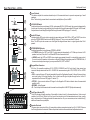
Cinénova IR16
8-ZONES MULTI-SOURCE
IR DRIVEN AMPLIFIER
USER’S MANUAL
IR
Earthquake Sound Corporation
2727 McCone Avenue. Hayward, CA 94545
Phone: 510-732-1000
Fax: 510-732-1095
www.earthquakesound.com
Sound That Will Move You.
Cinénova-IR16 Power Amplifier
Table of Content
Getting Started
Safety Instructions . . . . . . . . . . . . . . . . . . . . . . . . . . . . . . . . . . .
4-5
Introduction . . . . . . . . . . . . . . . . . . . . . . . . . . . . . . . . . . . . . . . .
6
Unpacking . . . . . . . . . . . . . . . . . . . . . . . . . . . . . . . . . . . . . . . . .
7
Basic Operations
Front & Rear Panel Overview . . . . . . . . . . . . . . . . . . . . . . . . . .
8
Front Panel Map . . . . . . . . . . . . . . . . . . . . . . . . . . . . . . . . . .
9
Rear Panel Map - LOCAL . . . . . . . . . . . . . . . . . . . . . . . . . . . .
10
Rear Panel Map - BUS . . . . . . . . . . . . . . . . . . . . . . . . . . . . . . .
11
Keypad & Remote Map . . . . . . . . . . . . . . . . . . . . . . . . . . . . . . . .
12
Special Features . . . . . . . . . . . . . . . . . . . . . . . . . . . . . . . . . . .
13
Features Explained . . . . . . . . . . . . . . . . . . . . . . . . . . . . .
14
IR Wiring Configuration Sample . . . . . . . . . . . . . . . . . . . . . . . .
15
Recommended Configuration . . . . . . . . . . . . . . . . . . . . . . . .
16
Specifications
Specifications . . . . . . . . . . . . . . . . . . . . . . . . . . . . . . . .
17
Troubleshooting & Maintenance
Troubleshooting & Maintenance . . . . . . . . . . . . . . . . . . . . . . . .
18
Product Warranty
Product Warranty . . . . . . . . . . . . . . . . . . . . . . . . . . . . . . . . .
19
3
Earthquake Sound
Safety Instructions
Safety First
This documentation contains general safety, installation, and operating instructions for the Cinénova-IR16 Amplifiers. It is
important to read this users’ manual before attempting to use these products. Pay particular attention to the safety
instructions.
Symbols Explained:
Appears on the component to indicate the presence of uninsulated, dangerous voltage inside the enclosure –
voltage that may be sufficient to constitute a risk of shock.
Calls attention to a procedure, practice, condition or the like that, if not correctly performed or adhered to, could result
in injury or death.
Calls attention to a procedure, practice, condition or the like that, if not correctly performed or adhered to, could result
in damage to or destruction of part or all of the product.
Note:
Calls attention to information that is essential to highlight.
© 2008 Earthquake Sound Corporation. All rights reserved.
This document should not be construed as a commitment on the part of Earthquake Sound Corporation. The information is subject to change without notice.
Earthquake Sound Corporation assumes no responsibility for errors that may appear within this document.
The Sound That Will Move You.
Earthquake Sound Corporation
2727 McCone Avenue
Hayward, CA 94545
Tel: 510-732-1000
Fax: 510-732-1095
Customer Support
[email protected]
Tel: 800-576-7944
Fax: 510-732-1095
4
Cinénova-IR16 Power Amplifier
Safety Instructions
Important Safety Instructions
1) Read these instructions in their entirety.
10) Protect the power cord from being walked on or pinched,
particularly at plugs, convenience receptacles, and the pint
where they exit from the apparatus.
2) Store this manual and packaging in a safe place.
3) Heed all warnings.
11) Only use attachments & accessories specified by the
manufacturer.
4) Follow instructions (do not take short cuts).
12) Use only compatible rack or cart for final resting position.
5) Do not use this apparatus near water.
13) Unplug this apparatus during lighting storm or when unused
for long period of time.
6) Clean only with a dry cloth.
7) Do not block any ventilation openings. Install in accordance
with the manufacturers instructions.
14) Refer all servicing to qualified service personal. Servicing is
required when the apparatus has been damaged in any way
such as; power-supply cord or plug is damaged, liquid has
been spilled or objects have fallen into the apparatus, the
apparatus has been exposed to rain or moisture, does not
operate normally, or has been dropped.
8) Do not install near any heat sources such as radiators, heat
registers, stoves, or other apparatuses that produce heat.
9) Do not defeat the safety purpose of the polarized or
grounding-type plug. A polarized plug has two blades with
one wider that the other. A grounding-type plug has two
blades and a third grounding prong. The wide blade or the
third prong is provided for your safety. If the provided plug
does not fit into your outlet, consult an electrician for
replacement of the obsolete outlet.
This triangle, which appears on your component,
alerts you to the presence of uninsulated,
dangerous voltage inside the enclosure voltage that may be sufficient to
constitute a risk of shock.
15) To reduce the risk of fire or electric shock, do not expose
this apparatus to rain or moisture.
This triangle, which appears on your component,
alerts you to important operating and
maintenance instructions in this
accompanying literature.
CAUTION
RISK OF ELECTRIC SHOCK
DO NOT OPEN
5
Earthquake Sound
Introduction
About Cinénova-IR16
The Cinénova-IR16 is the second generation in multi-zone that Earthquake has produced. Thanks to the feedbacks received from custom home
installers worldwide, we have managed present you with a truly powerful yet audiophile multi-zone amplifier with the following features:
!
!
!
!
!
!
!
!
!
Bridgeable output
Zone IR control with digital pad in each zone (included)
Décor friendly keypad
Four (4) built-in IR repeaters
Rear gain control limiter which limits the output gain of the zone pad.
Each zone has a LOCAL/BUS input audio selector
12V DC trigger
Individually driven amplifier blocks (each block is driven by a discrete complementary output class A/B stage with selected components)
Individual power supplies(bifilars) for power isolation, accuracy and better channel separation
There is no other multi-zone amplifier on the market with such features and power. Enjoy.
Over the years, many of you have provided us with design requirements, new product development ideas and tremendous
feedback that helped us to improved our products. We are very grateful for your support and feedback.
From all of us here at Earthquake Sound Corporation: Thank you.
Professor Joseph J. Sahyoun
President & Chief Engineer
6
Cinénova-IR16 Power Amplifier
Unpacking
Connection tips
Unpacking system components
!
Keep the original carton and packing materials for future
shipment or storage.
!
It is recommended that the Cinénova-IR16 and the source
equipment be plugged into a dedicated 20-amp circuit with an
isolated ground.
!
Disconnect all live power cords before making connections to the
remote gain.
!
Keep all power cords away from all signal cables to prevent
humming from induced noise.
! Check for any visual signs of damage. If you encounter any
concealed damage, consult your Earthquake Sound dealer
before proceeding with unit installation.
! Retain the sales receipt as it established the duration of the
limited warranty and provided information for insurance
purposes.
! Choose reliable signal cables cords (Earthquake Sound also
Cinénova-IR16 included components
•
•
•
•
•
•
specializes in high-performance RCA cables and patches).
1 Power cord
8 Remote controls
8 Keypads (wallplates not included)
8 Phoenix speaker terminals
8 Phoenix pad connectors
1 16-channel Amplifier
! All speaker wires that are ran through the walls should be twisted
type to reduce potential hum noise pick up.
! Label both ends of all wires with the corresponding room
location.
System installation considerations
! It is best to use a grounded electrical outlet to power the
amplifier. Lack of input ground reference could be unsafe.
Consult with your electrical contractor about proper grounding.
There are several factors to consider before installing the Earthquake
Sound Cinénova-IR16 system.
• What are the intended listening zones?
• What system options and accessories might be required for
features such as local sources, etc.?
• From where in each zone will the listener prefer to control the
system? Where will the remote gains be located? Where will the
speakers be located?
• Where will the source equipment be located?
Note: The Cinénova-IR16 must have adequate ventilation above and
below for air circulation and heat dissipation. In addition, rack mount
locations may require fans and vents.
7
Earthquake Sound
Front & Rear Panel Overview
13
9
5
1
14
10
6
2
15
11
7
3
16
12
8
4
4” (101.5mm)
6.876” (174.5mm)
19” (482.6mm)
16
Cinénova
IR
C to C 18.375” (466.5mm)
17” (431mm)
L
R
L
R
L
R
L
R
L
R
L
R
L
R
L
R
L
R
SPEAKER OUTPUT
R
L
R
L
R
L
R
L
R
L
R
L
R
L
R
L
FUSE
M
M
M
M
M
M
8
M
M
110-120VAC-60Hz
220-240VAC-50Hz
6.71” (170.5mm)
R
L
Cinénova-IR16 Power Amplifier
Front Panel Map
Front Panel
13
9
5
1
14
10
6
2
15
11
7
3
16
12
8
4
16
Cinénova
IR
3
1
2
1 Power/Standby Switch
This red colored LED indicates whether the amplifier is ON or OFF. When the amplifier is ON, this LED will be lit.
Note: When using the rear 12V DC Trigger (page 11 - feature 11), this front switch must be turned OFF.
2 Front Panel Power LED
This LED reflects the power status of the whole amplifier. Amplifier will not have any output unless this LED is ON.
Note: When using another device to turn on the Cinénova IR16 amplifier, this LED will come on when external device sends DC signal (between 5 and 28V
DC) to the back of Trigger connector (page 11 - feature 11).
3 Peak LED Indicators
Each LED represents one (1) channel. This particular model has sixteen (16) channels. Thus, there are sixteen (16) LEDs located on the front panel.
(!) Cinénova IR16 can be mounted in a standard rack mount (4 rack spaces).
(!) Mounting Dimensions: 4” center to center vertical and 18.37” center to center wide.
9
Earthquake Sound
Rear Panel Map - LOCAL
1V
1
LEVEL
3V
0.2V
2
BUS
LOCAL
3
1
STEREO
4
MONO
IR IN
STATUS
GROUND
CI
5
FFI
6
FFI
7
BRIDGE
R
L
L
R
L
R
L
R
L
R
L
R
L
R
L
R
L
R
L
R
1 Level Controls
This feature adjusts the maximum desired output of the associated zone to prevent overpowering of small
speakers.
Note: This knob is by-passed when its zone selector switch(feature 2) is set to BUS.
2 LOCAL/BUS Switch
It switches the audio source between LOCAL and common BUS. In LOCAL mode, the zone acts independently
from the rest of system by only amplifying the information fed through the associated RCA inputs. In BUS mode,
that particular zone will amplify the signal fed through the main BUS input (page 11 - feature 9).
3 Audio RCA Input
Individual stereo RCA inputs to drive signal into associated zones. Both RCA’s, LEFT and RIGHT, are active
when the STEREO/MONO switch is set to MONO (feature 4). Thus, you can use either RCA inputs.
Note: This RCA input also serves as an Auto Signal Sensing whenever there is a signal greater than 12mV
present.
4 STEREO/MONO Selector
Switches the amplifier’s output between STEREO or MONO.
·
In STEREO mode, the LEFT and RIGHT outputs operate independently at 75 Watts per channel at 4Ù
speaker load. Level, Gain, Auto Turn ON and MUTE are all common to both.
·
In MONO mode, the LEFT and RIGHT stereo signals are summed internally for a single high power output.
You can drive two 4Ù speakers in this mode or a single 4Ù Bridged for maximum power of 150WRMS. Also, if
the source is already a mono signal, you may use either RCA, LEFT or RIGHT.
5 Keypad/Zone Connector
With four (4) removable conductors (IR IN, STATUS, GROUND and CI–Control Input), these screw type
connector accepts wire sized from 24 to 12 AWG. We recommend using the CAT5, CAT5E, CAT6 or CAT6E
wires.
·
IR IN – receive all types of IR signal transmitted through the Earthquake Keypad. It allows Volume up/down
and mute function at the local amplifier. Also, it allows most IR signal to pass through the four built-in IR
repeaters of the Cinénova 16IR (page 11 - feature 12).
·
STATUS – this connector delivers DC signal to the Keypad’s LED status indicator when the associated
amplifier is ON.
·
GROUND – for the Keypad.
·
CI – Control Input is the communicator line used to control amplifier’s ON/OFF (Mute) status manually.
6 Fault Fuse Indicator (FFI)
This LED indicates the safe operation of the amplifier’s internal circuit for the associated zone. Under normal
condition, this LED is off. When it is lit, the fuse on the internal circuit of that associated zone is blown, usually
due to a shorted circuit. Simply replace with the same size fuse. For your convenience, we’ve included four (4)
additional fuses with every amplifier.
SPEAKER OUTPUT
R
L
R
L
R
L
R
L
R
L
R
L
R
L
R
L
FUSE
M
M
M
M
M
M
M
M
110-120VAC-60Hz
220-240VAC-50Hz
7 Speaker Terminals
This screw type connector with four (4) removable conductors accepts wire sizes from 16 to 12 AWG. Observe
the Polarity printed on the terminal. Observe the printed instruction above and below the Speaker terminal.
10
Cinénova-IR16 Power Amplifier
Rear Panel Map - BUS
8 Common BUS Level Controller
This potentiometer controls the output level on all individual amplifiers that are switched to BUS mode. It also
acts as a volume limiter to protect the speakers and amplifier itself.
1V
9 Common BUS Audio RCA Input
This pair of RCA drives a stereo signal into all zones that are switched to BUS mode. It allows one (1) source to
control as many as 8 zones’ audio out.
8
LEVEL
3V
0.2V
BUS
9
10 RCA Line Out
This allows the audio signal applied to the BUS RCA inputs to pass through unaltered to another device in the
system.
10
11 12V DC Trigger
It is the remote turn on option driven by a controlled 12V DC source or an AC/DC converter. The relay operating
range is between 5V DC and up to 28V DC. This remote turn on option does not override the auto signal sensing
turn on feature of this amplifier.
Note: The front power switch (page 9 - feature 1) must be left in the OFF position in order to for this function to
work.
12
IR Outputs
Four (4) amplified IR repeaters to repeat signals and commends fed through individual Earthquake Keypads.
13
Power Connection
This three (3) prong AC line connector is factory preset to 120VAC. However, other voltages are also available.
14
Main Power Fuse
Always replace the protection fuse with a similar value fuse. Please follow the fuse rating below:
115V, T15AL/250V
230V, T10AL/250V
LINE OUT
+12VDC
TRIGGER
11
1
2
12
IR OUT
3
4
13
14
FUSE
110-120VAC-60Hz
220-240VAC-50Hz
R
L
L
R
L
R
L
R
L
R
L
R
L
R
L
R
L
R
L
R
SPEAKER OUTPUT
R
L
R
L
R
L
R
L
R
L
R
L
R
L
R
L
FUSE
M
11
M
M
M
M
M
M
M
110-120VAC-60Hz
220-240VAC-50Hz
Earthquake Sound
Keypad & Remote Map
1 LED Status
This red colored LED indicates whether the amplifier is ON or OFF. When the amplifier is ON, this LED will be lit.
1
2
3
4
2 Volume Up/Down
This allows you to manually control the volume level up or down. The volume increases and decreases at the
same rate.
Note: This amplifier will hold the user defined volume setting for up to 3 hours from the last shut down.
Otherwise, the amplifier will start with volume position set to minimum to prevent undesired loud music in
unattended areas.
3 Mute
This allows you to mute or un-mute the associated amplifier(s) output.
4 IR Receiver
This feature allows the communication of all IR information between the Keypad and the rest of the system.
Coded signal controls the individual volume at each channel while other IR information can pass through
unaltered to the rest of the components connected to the provided IR out repeaters (page 11 - feature 12).
Note: Wallplates are not included
(!) NOTE: One Keypad is capable of driving multiple zones. Simply connect the CI wire of those zones in
parallel. For example, if you want to use the Keypad from zone 1 to control zone 1 through 5, remove the
Keypad connecting wires from zone 2 through 5 and parallel the CI wire of zone 2 through 5 to the CI of
zone 1.
(!) NOTE: If a zone is not connected to a Keypad, the speaker output will be muted (no audio output to
the speaker) unless you parallel connect that zone’s CI wire to another zone’s CI.
KEYPAD
1
MUTE
ZONE
1
ZONE
2
ZONE
3
ZONE
4
ZONE
5
ZONE
6
ZONE
7
ZONE
8
KEYPAD
8
KEYPAD
7
KEYPAD
6
1
VOL+
VOL-
2
In addition to the eight (8) Earthquake Keypads, we also provide you with remote controls that have the same
functions – Volume Up/Down and Mute. For your convenience, the remote information can be taught to any
remote with learning capability.
1 Mute
This allows you to mute or un-mute the associated amplifier(s) output.
2 Volume Up/Down
This allows you to manually control the volume level up or down. The volume increases and decreases at the
same rate.
12
Cinénova-IR16 Power Amplifier
Special Features
Special Features
Eight individual power supplies:
Rack mountable:
The Cinénova-IR16 is designed with 8 individual power
supplies(bifilar) for power isolation, accuracy and better channel
separation.
This amplifier is designed to conveniently mount in commonly
used racks.
Peak LED indicators:
110V AC and 220V AC selectable:
The Cinénova-IR16 is equipped with 16 LED indicators on the
front panel. They show the operating status of each channel; the LEDs
will illuminate when the maximum recommended output is exceeded.
If an LED is illuminated the majority of the time, it indicates that the
corresponding channel is over-driven (clipped). The input to the
channel must be reduced to eliminate distortion and eventually,
damages to the amplifier.
The Cinénova-IR16 is factory preset to 110-120VAC. However,
it can also be set to accommodate 220-240VAC by Earthquake
authorized technician(s)/dealer(s).
Remote zone control:
Each of the eight possible zones can be controlled by a wireless
IR remote control. Each remote has the ability to control volume’s
up/down level, mute and also repeat the IR signal to other sources.
Thermal protection:
Bus input:
Each channel is equipped with a thermal sensor designed to
shut the amplifier down when it overheats. Overheating is not typical. It
only occurs if the amplifier is over driven with low impedance speakers,
or if the amplifier is located in an improperly ventilated space.
This feature simplifies installation by consolidating several
channels for one source. Simply plug the input source RCAs into the
BUS input on the unit. Then switch the input source selector to BUS for
as many channels are connected to the corresponding input source.
Individually selected and matched components:
Bridgeable function (minimum impedance = 4-ohm):
Components used to construct the Cinénova-IR16 are
subjected to an exhaustive selection process; during which, the
components are matched and individually tested to exact tolerance.
The multi-layer, glass-epoxy, double sided printed circuit boards
exceed the standard stringent requirements by 50%.
The Cinénova-IR16 delivers up to 8-zones, and can be bridged
into several different configurations for higher power rooms.
4 or 8-ohm compatible:
8-Zones:
Since speakers are manufactured in several different
impedance ratings, Earthquake Sound’s Cinénova-IR16 amplifier is
designed to be 4 and 8-Ohm compatible.
The Cinénova-IR16 delivers up to 8-zones, and several other
room combinations to better suite the your needs.
13
Earthquake Sound
Features Explained
R
L
L
L
R
R
L
R
L
R
L
R
L
R
L
L
R
R
L
R
SPEAKER OUTPUT
R
L
R
L
R
L
R
L
R
L
R
L
R
L
R
L
FUSE
M
M
M
M
M
M
M
M
Amplifier section Explained
110-120VAC-60Hz
220-240VAC-50Hz
BUS section Explained
Rear Gain Control Limiter (RGCL)
It controls the front pad maximum output power from over
powering small speakers. The module RGCL will limit the
output only when the RCA input selection is set to MAIN
(not Bus).
Input Signal Control(ISC)
When switched to LOCAL, individual
inputs will drive each individual
amplifier.
When selecting BUS, the audio
input from the BUS will drive the
amplifier.
Bus Control Limiter (BCL)
It controls the front pad maximum output power
from over powering small speakers. The module
BCL would limit the output power of any amplifier
that uses the bus as a signal source.
L
L
R
R
Keypad Front view
L
Bus RCA input signal
Stereo input signal RCA that delivers the signal to
the bus. It also allows you do daisy chain the
signal to additional Cinénova amplifiers.
R
Mono/ Stereo input control
You must switch to MONO when the amplifier
is wired for MONO
DC TRIGGER
12 Volt DC trigger to be connected to source
output 12 volt trigger. For this to operate, you need
to switch the front panel switch to OFF.
Phoenix type connector
Should be wired using CAT5 or 5e, CAT6 or 6e.
This allows zone control via IR. This must be
connected to the zone pad.
Speaker output terminal
For stereo applications, please follow the
polarity that is shown on top. For MONO
follow the bottom polarity.
Please note that FFI is a Fault Fuse
Indicator. Any amplifier that has the FFI
LED light on will require a fuse replacement
or possibly service.
R
L
-
Keypad Rear view
M
14
4 IR repeater
The Cinénova-IR16 has four output IR that
combine any or all zone IR input. These repeater
will repeat the sum of IR signal to control any
source input. Please note that you will need to use
your source remote, aim it at the pad and it will
deliver the IR signal to the source.
Cinénova-IR16 Power Amplifier
IR Wiring Configuration Sample
The Cinénova 16 IR allows you to connect several sources to the input stage of the amplfier. It also allows you to aim the remote
at the zone pad and use the source remote control. As you aim the remote to the pad, the IR signal is transmitted from the pad to
the amplifier and thereafter amplified. There are four repeaters on the back of the amplifier that can be connected to the source IR
sensor. Once connected, the user can control the source from the room. the illustration below has a DVD player connected to the
IR repeater. Please note that the remote in use is that of the DVD player.
R
L
L
R
L
R
L
R
L
R
L
R
L
R
L
R
L
R
L
R
IR
repeater
SPEAKER OUTPUT
R
L
R
L
R
L
R
L
R
L
R
L
R
L
R
L
FUSE
M
M
M
M
M
M
M
M
110-120VAC-60Hz
220-240VAC-50Hz
Keypad Front view
Source:DVD player
IR
Keypad Rear view
Remote:DVD player
15
Earthquake Sound
Recommended Configuration
R
L
L
R
L
R
L
R
L
R
L
R
L
R
L
R
L
R
L
R
SPEAKER OUTPUT
R
L
R
L
R
L
R
L
R
L
R
L
R
L
R
L
FUSE
M
M
150 Watts RMS/Per Channel
1-High Power Zones
MONO/Bridged
M
M
M
M
75 Watts RMS/Per Channel
Background room(s)
6-Zones STEREO
16
M
M
110-120VAC-60Hz
220-240VAC-50Hz
Cinénova-IR16 Power Amplifier
Specifications
SPECIFICATIONS
• Number of channels
16 Channels
• Power rating per channel
(4-Ohm stereo), all channels driven:
(4-Ohm bridged), 8 channels:
(8-Ohm stereo), all channels driven:
(8-Ohm bridged), 8 channels:
75 Watts RMS
150 Watts RMS
50 Watts RMS
100 Watts RMS
• Frequency response:
• Dimensions
Face plate (W x D x H): 19” (482.6mm) x 0.47” (12mm) x 6.87” (174.5mm)
18.37” (466.5mm) x 4” (101.5mm)
Mounting (W x H):
Chassis (W x D x H): 16.65” (423mm) x 17” (405mm) x 6.71” (170.5mm)
WC
DC
20Hz - 20kHz at -0.3dB
• Total Harmonic Distortion - THD:
HC
0.01%
• Input sensitivity (for rated output power):
200mV - 3V
WM
HF
16
Cinénova
HM
IR
• Input impedance
Independent channels
Bus Input
22 kÙ
70 kÙ
• Signal to noise ratio:
92dB
• AUTO OFF delay time:
12 minutes
• Crosstalk:
>86dB
• Slew rate:
50V/ìsec
• Gain:
• Damping Factor:
• Remote trigger voltage:
• Power requirement:
• Fuse ratings:
Main power fuse:
Block fuse:
• Weight
Net weight:
Gross weight:
WF
29
> 200 @ 8Ù
5.5 - 28 VDC
15 Amp 120VAC 60Hz / 10 Amp 220VAC 50Hz
FOR YOUR RECORDS
Date of purchase:
_________________________________
Serial number:
_________________________________
Authorized dealer name:
_________________________________
Dealer’s address:
_________________________________
115V,T15A/250V / 230,T10A/250V
3 AG type, slow blow 5A/250V
_________________________________
_________________________________
61.7 lbs / 28 kg
66.1 lbs / 30 kg
17
Dealer’s phone number:
( _______ ) ________ - _____________
Earthquake Sound
Troubleshooting and Maintenance
Troubleshooting
Maintenance
The following routine maintenance should be performed on a periodic
basis:
Humming noise from speakers.
Often humming noise is emanating from equipments that
have their ground prong broken.
?
Clean the exterior surfaces of the unit with a soft, dry, lint-free cloth.
?
Do not use alcohol, benzene, acetone-based cleaners, or strong
commercial cleaners.
?
Do not use a cloth made with steel wool or metal polish.
?
If the unit is exposed to a dusty environment, a low-pressure
blower may be used to remove dust from its interior & exterior.
a) With the amplifier OFF, unplug all RCAs connected to the
amplifier.
b) Turn on amp and listen to speakers.
If buzz has changed or reduced in level, then the problem
is coming to the amp from another source. The rest of the
hum you hear is normal and related to the fact that the
RCAs are open ended and not connected to any thing.
c) If above steps do not isolate your problem: star-ground all
components except amplifier from their chassis to the
processor.
Front LEDs are ON all the time
It is normal when running the amplifier to full power that the LEDs
flicker. If you see that the LEDs are on constantly without
flickering (solid orange) it means that the amplifier is clipping.
Reduce volume level to prevent damage to the unit.
Turn amplifier ON and circuit breaker shuts down
This can either be a short in amp or poor circuit breaker in the
house. Plug amplifier into another outlet on a different circuit
breaker with nothing connected. If the amp turns on then the
problem is with your home circuit breaker. If the amplifier still does
not power up, please call Earthquake to consult with a technician.
Note:
Visit www.earthquakesound.com for answers to frequently asked
questions and additional troubleshooting information.
If you are still stuck...
1. Contact an authorized Earthquake Dealer.
2. Contact Earthquake Sound Customer Service at 800-576-7944
18
Cinénova-IR16 Power Amplifier
Product Warranty
Five (5) year limited warranty
Earthquake warrants the original purchaser that all Factory Sealed New Audio
Products to be free from defects in material and workmanship under normal
and proper use for a period of five (5) years from the date of purchase (as shown
on the original bill of sale with serial number affixed/written on it). The five (5)
year warranty period is valid only if an authorized Earthquake dealer properly
installs the product and the warranty registration card is properly filled out and
sent to Earthquake Sound Corporation. If a non-authorized party installs the
product, a ninety (90) day warranty period will be applied.
surround & dust cap, burnt speaker voice coil.
• Fading and or deterioration of speaker components & finish due to
improper exposure to elements.
• Bent amplifier casing, damaged finish on the casing due to abuse, misuse
or improper use of cleaning material.
• Burnt tracers on PCB.
• Product/part damaged due to poor packaging or abusive shipping
conditions.
• Subsequent damage to other products.
(A) Five (5) years limited warranty plan coverage guidelines:
A
warranty claim will not be valid if the warranty registration card is not
properly filled & returned to Earthquake with a copy of the sales invoice.
Warranty card is located on the last page of this manual.
• First year: Earthquake pays for labor, parts, and ground freight (only in US
mainland, not including Alaska and Hawaii) (shipping to us is not covered).
• Second year: Earthquake pays for labor and parts only, customer must pay
freight both ways.
• Third, fourth & fifth year: Earthquake pays labor only. Customer must pay
for parts and freight both ways.
(E) Service Request:
To receive product service, contact Earthquake service department at (510)
732-1000 and request an RMA number (Return Material Authorization). Items
shipped without a valid RMA number will be refused. Make sure you provide us
with your complete/correct shipping address, a valid phone number, and a brief
description of the problem you are experiencing with the product. In most cases,
our technicians might be able to resolve the problem over the phone; thus,
eliminating the need to ship the product.
(B) Warning:
Products (sent for repair) that are tested by Earthquake technicians and
deemed to have no problem(s) will not be covered by the five (5) year limited
warranty. Customer will be charged a minimum of one (1) hour of labor (at the
ongoing rates) plus shipping charges back to customer.
(F) Shipping Instructions:
(C) Earthquake will repair or replace - at our option - all defective
products/parts subject to the following provisions:
• Defective products/parts have not been altered or repaired by other than an
Earthquake factory-approved technician.
• Products/parts are not subjected to negligence, misuse, improper use or
accident, damaged by improper line voltage, used with incompatible products
or have its serial number or any part of it altered, defaced or removed, or have
been used in any way that is contrary to Earthquake's written instructions.
Product(s) must be packaged in its original protective box(es) to minimize
transport damage. Shipper claims regarding items damaged in transit must be
presented to carrier. Earthquake Sound Corporation reserves the right to refuse
improperly packed product. Original bill of sale must accompany product
returned for service. We encourage you to include with the package a written
description of the problem. Ship product to: Earthquake Sound Corp. 2727
McCone Avenue, Hayward, CA 94545. Ph (510) 732-1000. You are responsible
for the cost of shipping the product to Earthquake Sound Corporation.
(D) Warranty Limitations:
(G) Disputes Resolution:
Warranty does not cover products that have been modified or abused,
including but not limited to the following:
• Damages to speaker cabinet and cabinet finish due to misuse, abuse or
improper use of cleaning materials/methods.
• Bent speaker frame, broken speaker connectors, holes in speaker cone,
All disputes - between clients and Earthquake Sound Corporation - resulting
from the five (5) years limited warranty policy must be resolved according to the
laws & regulations of the county of Alameda -California.
We recommend that you place or write
your serial number here for future
reference, if necessary.
PRODUCT REGISTRATION
This Cinénova-IR16 Power Amplifier can be registered by returning the Product Registration card attached to this
manual or by visiting www.earthquakesound.com. Please also retain the bill of sale, which represents proof of
purchase and helps expedite warranty issues.
19
SERIAL NUMBER
Sound That Will Move You.
Earthquake Sound reserves the right to amend details of the specifications without notice
Copyright © Earthquake Sound Corporation
Earthquake Sound Corporation | 2727 McCone Avenue. Hayward, CA 94545 | Phone: 510-732-1000 Fax: 510-732-1095