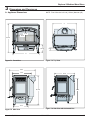
1
Installation Manual
Installation & Appliance Set-Up
INSTALLER: Leave this manual with party responsible for use and operation.
OWNER: Retain this manual for future reference.
NOTICE: DO NOT DISCARD THIS MANUAL
WARNING
If the information in these instructions is not followed exactly, a
fire may result causing property
damage, personal injury, or death.
Explorer II Medium Wood Stove
Model(s):
EXPLRMED-PBK
EXPLRMED-PDB
EXPLRMED-PFT
EXPLRMED-PMH
EXPLRMED-MBK
• Do not store or use gasoline or other flammable vapors and liquids in the vicinity of
this or any other appliance.
• Do not overfire - If heater or chimney connector glows, you are overfiring. Overfiring
will void your warranty.
• Comply with all minimum clearances to
combustibles as specified. Failure to
comply may cause house fire.
WARNING
HOT SURFACES!
Glass and other surfaces are hot
during operation AND cool down.
WARNING
Fire Risk.
For use with solid wood fuel only.
Other fuels may overfire and generate
poisonous gases (i.e. carbon monoxide).
Hot glass will cause burns.
•
Do not touch glass until it is cooled
•
NEVER allow children to touch glass
•
Keep children away
•
CAREFULLY SUPERVISE children in same room as
fireplace.
•
Alert children and adults to hazards of high temperatures
•
High temperatures may ignite clothing or other
flammable materials.
•
Keep clothing, furniture, draperies and other flammable
materials away.
NOTE
Installation and service of this appliance should
be performed by qualified personnel. Hearth &
Home Technologies recommends NFI certified
professionals, or technicians supervised by an
NFI certified professional.
1
To obtain a French translation of this manual, please contact
your dealer or visit www.quadrafire.com
Pour obtenir une traduction française de ce manuel, s’il vous
plaît contacter votre revendeur ou visitez www.quadrafire.com
7061-197D
November 7, 2014
Explorer II Medium Wood Stove
Safety Alert Key:
•
DANGER! Indicates a hazardous situation which, if not avoided will result in death or serious injury.
•
WARNING! Indicates a hazardous situation which, if not avoided could result in death or serious injury.
•
CAUTION! Indicates a hazardous situation which, if not avoided, could result in minor or moderate injury.
•
NOTICE: Indicates practices which may cause damage to the appliance or to property.
TABLE OF CONTENTS
1 Important Safety Information .............3
A. Appliance Certification ......................................................3
B. BTU & Efficiency Specifications........................................3
C. Mobile Home Approved (USA ONLY) ............................... 3
D. Glass Specifications .........................................................3
E. Non-Combustible Materials ...............................................3
F. Combustible Materials ........................................................3
2 Getting Started ....................................4
A. Design and Installation Considerations .............................4
B. Fire Safety .........................................................................4
C. Negative Pressure ............................................................5
D. Tools And Supplies Needed..............................................5
E. Inspect Appliance and Components .................................5
F. Install Checklist ..................................................................6
4 Chimney Systems .............................11
A. Venting Components .......................................................11
B. Chimney Systems .............................................................11
C. Installing Chimney Components ........................................13
5 Appliance Set-Up ..............................14
A. Hearth Protection Requirements ......................................14
B. Outside Air Kit Installation .................................................15
C. Blower (Optional) ..............................................................16
D. Reversible Flue Collar and Horizontal Flue Heat Shield ..17
6 Mobile Home Installation..................18
7 Accessory List ..................................19
3 Dimensions and Clearances ..............7
A. Appliance Dimensions ......................................................7
B. Clearances to Combustibles ..............................................8
C. Locating Your Stove & Chimney .......................................9
D. Chimney Termination Requirements ................................9
E. 2-10-3 Rule ......................................................................10
Quadra-Fire is a registered trademark of Hearth & Home Technologies.
2
7061-197D
November 7, 2014
Explorer II Medium Wood Stove
1
Important Safety Information
A. Appliance Certification
Model:
Explorer II Medium Wood Stove
Laboratory:
Intertek
Report No:
10126132PRT
Type:
Safety
Standard:
UL 1482-07; ULC S627-00
WARNING
Fire Risk.
Hearth & Home Technologies disclaims any
responsibility for, and the warranty will be voided
by, the following actions:
The Quadra-Fire Explorer Series Wood Stove (ACC) meets
the U.S. Environmental Protection Agency’s 1990 particulate
emission standards.
B. BTU & Efficiency Specifications
EPA Certification #: 925
•
•
•
•
•
EPA Certified Emissions: 2.17 grams per hour
•
*EPA Default Efficiency: 63%
**EPA Tested Efficiency: 79.9%
•
***EPA BTU Output: 11,200 to 35,900
****Peak BTU/Hour Output: 65,800
Any such action that may cause a fire hazard.
Vent Size: 6 inches
Improper installation, adjustment, alteration, service or
maintenance can cause injury or property damage.
For assistance or additional information, consult a qualified
installer, service agency or your dealer.
Firebox Size: 2.4 cubic feet
Maximum Wood Length: 20 inches
Ideal Wood Length: 18 inches
Fuel Seasoned Cord Wood
*EPA Default Efficiency: An efficiency based on EPA historical
data: 63% for non-catalytic stoves and 72% for catalytic stoves.
**EPA Tested Efficiency: An average efficiency calculated using
Douglas Fir dimensional lumber and data collected during EPA
emissions tests.
***EPA BTU Output: A range of BTU outputs based on EPA Default Efficiency and the burn rates from the low and high EPA
tests, using Douglas Fir dimensional lumber.
****Peak BTU/Hour output: A peak BTU out of the unit calculated using the maximum first hour burn rate from the High EPA Test
and the BTU content of cordwood.
C. Mobile Home Approved (USA ONLY)
• This appliance is approved for mobile home installations in the USA when not installed in a sleeping room
and when an outside combustion air inlet is provided.
• The structural integrity of the mobile home floor, ceiling, and walls must be maintained.
• The appliance must be properly grounded to the frame
of the mobile home with #8 copper ground wire, and
chimney must be listed to UL103 HT or a listed UL1777 full length six inch (152mm) diameter liner must
be used.
• Outside Air Kit, part OAK-ACC must be installed in a
mobile home installation.
NOTE: This installation must conform with local codes. In the
absence of local codes you must comply with the UL1482-07,
(UM) 84-HUD and NPFA211 in the U.S.A. and the ULC S62700 and CAN/CSA-B365 Installation Codes in Canada. NOT
APPROVED FOR MOBILE HOME INSTALLATIONS IN
CANADA!
November 7, 2014
Installation and use of any damaged appliance.
Modification of the appliance.
Installation other than as instructed by Hearth & Home
Technologies.
Installation and/or use of any component part not approved
by Hearth & Home Technologies.
Operating appliance without fully assembling all
components.
Operating appliance without legs attached (if supplied with
it).
Do NOT Overfire - If appliance or chimney connector glows,
you are overfiring.
NOTE: Hearth & Home Technologies, manufacturer of
this appliance, reserves the right to alter its products, their
specifications and/or price without notice.
Hearth & Home Technologies WILL NOT warranty stoves
that exhibit evidence of over-firing. Evidence of over-firing
includes, but is not limited to:
• Warped air tube
• Deteriorated refractory brick retainers
• Deteriorated baffle and other interior components
D. Glass Specifications
This stove is equipped with 5mm ceramic glass. Replace
glass only with 5mm ceramic glass. Please contact your
dealer for replacement glass.
E. Non-Combustible Materials
Material which will not ignite and burn, composed of any
combination of the following:
- Steel
- Plaster
- Brick
- Iron
- Concrete
- Tile
- Glass
- Slate
Materials reported as passing ASTM E 136, Standard
Test Method for Behavior of Metals, in a Vertical Tube
Furnace of 750° C.
F. Combustible Materials
Material made of/or surfaced with any of the following materials:
- Wood
- Compressed Paper
- Plant Fibers
- Plastic
- Plywood/OSB
- Sheet Rock (drywall)
Any material that can ignite and burn: flame proofed or not,
plastered or un-plastered.
7061-197D
3
Explorer II Medium Wood Stove
Install Guide
2
Getting Started
A. Design and Installation Considerations
WARNING
Consideration must be given to:
•
•
•
•
Fire Risk.
Safety
Convenience
Traffic flow
Chimney and chimney connector required
Hearth & Home Technologies disclaims any
responsibility for, and the warranty will be
voided by, the following actions:
• Installation and use of any damaged appliance.
• Modification of the appliance.
• Installation other than as instructed by Hearth & Home
Technologies.
• Installation and/or use of any component part not approved
by Hearth & Home Technologies.
• Operating appliance without fully assembling all components.
• Operating appliance without legs attached (if supplied with
unit).
• Do NOT Overfire - If appliance or chimney connector glows,
you are overfiring.
It is a good idea to plan your installation on paper, using exact
measurements for clearances and floor protection, before
actually beginning the installation. If you are not using an
existing chimney, place the appliance where there will be a
clear passage for a factory-built listed chimney through the
ceiling and roof.
We recommend that a qualified building inspector and your
insurance company representative review your plans before
and after installation.
If this appliance is in an area where children may be near it is
recommended that you purchase a decorative barrier to go
in front of the appliance. Remember to always keep children
away while it is operating and do not let anyone operate
this appliance unless they are familiar with these operating
instructions.
Any such action that may cause a fire hazard.
B. Fire Safety
To provide reasonable fire safety, the following should be
given serious consideration:
1.
• Installation MUST comply with local, regional, state and
national codes and regulations.
Install at least one smoke detector on each floor of
your home to ensure your safety. They should be
located away from the heating appliance and close
to the sleeping areas. Follow the smoke detector
manufacturer’s placement and installation instructions,
and be sure to maintain regularly.
2.
• Consult insurance carrier, local building, fire officials or
authorities having jurisdiction about restrictions, installation
inspection, and permits.
A conveniently located Class A fire extinguisher to
contend with small fires resulting from burning embers.
3.
A practiced evacuation plan, consisting of at least two
escape routes.
4.
A plan to deal with a chimney fire as follows:
CAUTION
Check building codes prior to installation.
In the event of a chimney fire:
a
b.
Evacuate the house immediately
Notify fire department
WARNING
NOTICE: HEARTH & HOME TECHNOLOGIES ASSUMES NO
RESPONSIBILITY FOR THE IMPROPER PERFORMANCE
OF THE APPLIANCE SYSTEM CAUSED BY:
Asphyxiation Risk.
• DO NOT CONNECT THIS UNIT TO A CHIMNEY
FLUE SERVICING ANOTHER APPLIANCE.
• DO NOT CONNECT TO ANY AIR DISTRIBUTION
DUCT OR SYSTEM.
May allow flue gases to enter the house.
4
•
Inadequate draft due to environmental conditions
•
Downdrafts
•
Tight sealing construction of the structure
•
Mechanical exhausting devices
•
Overdrafting caused by excessive chimney heights
•
Ideal performance is with height of chimney between 14-16 feet
(4.26-4.88m) measured from the base of the appliance.
7061-197D
November 7, 2014
Explorer II Medium Wood Stove
D. Tools And Supplies Needed
C. Negative Pressure
Before beginning the installation be sure the following tools
and building supplies are available:
WARNING
Asphyxiation Risk.
• Negative pressure can cause spillage of combustion fumes, soot and carbon monoxide.
• Appliance needs to draft properly for safety.
Negative pressure results from the imbalance of air available for the appliance to operate properly. It can be strongest in lower levels of the house.
Reciprocating saw
Framing material
Pliers
High temp caulking material
Hammer
Gloves
Phillips screwdriver
Framing square
Flat blade screwdriver
Electric drill and bits
Plumb line
Safety glasses
Level
Tape measure
Misc. screws and nails
Causes include:
1/2-3/4 in. length, #6 or #8 self-drilling screws
•
Exhaust fans (kitchen, bath, etc.)
•
Range hoods
•
Combustion air requirements for furnaces, water heaters
and other combustion appliances
•
Clothes dryers
•
Location of return-air vents to furnace or air conditioning
•
Imbalances of the HVAC air handling system
•
Upper level air leaks such as:
E. Inspect Appliance and Components
•
•
•
- Recessed lighting
Remove appliance and components from packaging and
inspect for damage.
Report to your dealer any parts damaged in shipment.
Read all the instructions before starting the installation.
Follow these instructions carefully during the
installation to ensure maximum safety and benefit.
- Attic hatch
- Duct leaks
To minimize the effects of negative air pressure:
•
Install the outside air kit with the intake facing prevailing
winds during the heating season
•
Ensure adequate outdoor air for all combustion appliances
and exhaust equipment
•
Ensure furnace and air conditioning return vents are not
located in the immediate vicinity of the appliance
•
Avoid installing the appliance near doors, walkways or
small isolated spaces
•
Recessed lighting should be a “sealed can” design
•
Attic hatches weather stripped or sealed
•
Attic mounted duct work and air handler joints and seams
taped or sealed
•
Basement installations should be avoided
November 7, 2014
WARNING
Fire Risk.
Inspect appliance and components for damage.
Damaged parts may impair safe operation.
• Do NOT install damaged components.
• Do NOT install incomplete components.
• Do NOT install substitute components.
Report damaged parts to dealer.
7061-197D
5
Explorer II Medium Wood Stove
F. Install Checklist
ATTENTION INSTALLER:
Follow this Standard Work Checklist
This standard work checklist is to be used by the installer in conjunction with, not instead of, the instructions contained in this installation manual.
Customer:
Date Installed:
Lot/Address:
Location of Fireplace:
Installer:
Dealer/ Distributor Phone #:
Serial #:
Model (circle one):
EXPLRMED-PBK
EXPLRMED-PDB
EXPLRMED-PFT
EXPLRMED-PMH
EXPLRMED-MBK
WARNING! Risk of Fire or Explosion! Failure to install fireplace according to these instructions can lead to a fire or explosion.
Appliance Install
YES
IF NO, WHY?
Verified clearances to combustibles. (Pg. 8)
Fireplace is leveled and connector is secured to appliance. (Pg. 19)
Hearth extension size/height decided. (Pg. 14)
Outside air kit installed. (Pg. 15)
Floor protection requirements have been met.
If appliance is connected to a masonry chimney, it should be cleaned and
inspected by a professional. If installed to a factory built metal chimney, the
chimney must be installed according to the manufacturer’s instructions and
clearances.
Chimney Section 4 (Pg. 11)
Chimney configuration complies with diagrams.
Chimney installed, locked and secured in place with proper clearance.
Chimney meets recommended height requirements (14-16 feet).
Roof flashing installed and sealed.
Terminations installed and sealed.
Clearances Section 3 (Pg. 7)
Combustible materials not installed in non-combustible areas.
Verified all clearances meet installation manual requirements.
Mantels and wall projections comply with installation manual requirements.
Protective hearth strips and hearth extension installed per manual requirements.
Appliance Setup Section 5 (Pg. 14)
All packaging and protective materials removed.
Firebrick, baffle and ceramic blanket installed correctly.
All labels have been removed from the door.
All packaging materials are removed from inside/under the fireplace.
Manual bag and all of its contents are removed from inside/under the fireplace
and given to the party responsible for use and operation.
Hearth & Home Technologies recommends the following:
• Photographing the installation and copying this checklist for your file.
• That this checklist remain visible at all times on the fireplace until the installation is complete.
Comments: Further description of the issues, who is responsible (Installer/Builder/Other Trades, etc.) and corrective action needed:
Comments communicated to party responsible
by
on
(Builder/Gen. Contractor)
(Installer)
(Date)
Part # 4017-254 • Rev B • 01/29/13
6
7061-197D
November 7, 2014
Explorer II Medium Wood Stove
3
Dimensions and Clearances
NOTE: Flue Collar size is 6 inch (152mm) diameter (ID)
A. Appliance Dimensions
29
12-1/4
20-1/16
28-15/16
7-15/16
3
27
Figure 7.2 Top View
Figure 7.1 Front View
26-3/4
19-1/2
22-3/16
28-15/16
25-7/8
14-7/8
Figure 7.2 Side View
November 7, 2014
Figure 7.4 Side View with horizontal flue
7061-197D
7
Explorer II Medium Wood Stove
B. Clearances to Combustibles
MINIMUM CLEARANCES TO COMBUSTIBLE MATERIALS in inches & (Millimeters)
NOTE: All A, B, and C Dimensions are to the center of the flue collar
A
B
C
D
INSTALLATION: FULL VERTICAL OR ALCOVE
For alcove only: Six inch diameter listed Double wall air insulated connector
pipe with UL103 HT listed factory built Class A chimney or masonry chimney.
Maximum depth of Alcove shall be no more than 48 inches (1220mm) with a
minimum height of 48 inches (1220mm) to top of unit and the referenced
clearances. Canada must comply with CAN/ULC-S269 M87 for the 650° factory
built chimney
SINGLE WALL PIPE
Explorer II
10.5 (267)
20.25 (514)
13.5 (343)
55 (1397)
9.38 (238)
20.25 (514)
10.5 (267)
55 (1397)
BACKWALL / SIDEWALL
A
B
DOUBLE WALL PIPE
Explorer II
* FOLLOW PIPE MANUFACTURES CLEARANCES AS REQUIRED
ALCOVE TOP VIEW
ALCOVE SIDE VIEW
CORNER INSTALLATION
C
D
B
A
C
HORIZONTAL THROUGH WALL
TOP AND SIDE VIEW
*
20.25
(514)
MANTEL
12” MAX
STOVE TO CEILING
CLEARANCE
D
50
(1270)
12
(305)
WARNING
Fire Risk.
• Comply with all minimum clearances to
combustibles as specified.
• Failure to comply may cause house fire.
NOTE: Clearances may only be reduced by means
approved by the regulatory authority having jurisdiction
8
7061-197D
November 7, 2014
Explorer II Medium Wood Stove
C. Locating Your Stove & Chimney
•
Location of the appliance and chimney will affect performance. As shown in Figure 9.1 the chimney should:
Consider the appliance location in order to avoid floor
and ceiling attic joists and rafters.
•
Locate termination cap away from trees, adjacent
structures, uneven roof lines and other obstructions.
•
Install through the warm space enclosed by the building envelope. This helps to produce more draft, especially during lighting and die down of the fire.
•
Penetrate the highest part of the roof. This minimizes
the affects of wind turbulence and down drafts.
Recommended
Location
Your local dealer is the expert in your geographic area and
can usually make suggestions or discover solutions that will
easily correct your flue problem.
Recommended
Location
Marginal
Location
Location
Not
Recommended
Location NOT
Recommended
Windward
Outside Air Kit Termination Cap
Leeward
Multi-level Roofs
Figure 9.1
D. Chimney Termination Requirements
Follow manufacturer’s instructions for clearance, securing
flashing and terminating the chimney. Fig. 10.1 & 10.2
• Must have an approved and Listed cap
• Must not be located where it will become plugged by
snow or other material
•
Must terminate at least 3 feet (91cm) above the roof
and at least 2 feet (61cm) above any portion of the
roof within 10 feet (305cm).
•
Must be located away from trees or other structures
NOTICE: Locating the appliance in a basement or in a
location of considerable air movement can cause intermittent
smoke spillage from appliance. Do not locate appliance near
•
Frequently open doors
•
Central heat outlets or returns
NOTICE:
•
•
•
Chimney performance may vary.
Trees, buildings, roof lines and wind conditions affect
performance.
Chimney height may need adjustment if smoking or
overdraft occurs.
November 7, 2014
7061-197D
9
Explorer II Medium Wood Stove
E. 2-10-3 Rule
These are safety requirements and are not meant to assure proper flue draft.
This appliance is made with a 6 inch (152mm) diameter chimney connector as the flue collar on the unit.
• Changing the diameter of the chimney can affect draft and cause poor performance.
• It is not recommended to use offsets and elbows at altitudes above 4000 feet above sea level and or when there
are other factors that affect flue draft.
Less than 10 ft. (305cm)
2 ft. (61cm)
2 ft. (61cm)
3 ft. (91cm)
Minimum
10 ft. (305cm) To Nearest Roofline
3 ft. (91cm)
Minimum
Pitched Roof
Figure 10.1
10 ft. (305cm) or more
Less than 10 ft. (305cm)
Wall or Parapet
2 ft. (61cm) Minimum
3 ft. (91cm) Minimum
3 ft. (91cm) Minimum
Flat Roof
Figure 10.2
10
7061-197D
November 7, 2014
Explorer II Medium Wood Stove
4
Chimney Systems
A. Venting Components
B. Chimney Systems
Chimney Connector:
Prefabricated Metal Chimney
• Must be minimum 6 inch (152mm) diameter (ID) high
temperature chimney listed to UL 103 HT (2100oF) or
ULC S629M.
It is also known as flue pipe or stove pipe. The chimney
connector joins the stove to the chimney. It must be a 6 inch
(152mm) minimum diameter 24 gauge mild steel black or 26
gauge blued steel, or an approved air-insulated double wall
venting pipe.
Thimble:
A manufactured or site-constructed device installed in
combustible walls through which the chimney connector
passes to the chimney. It is intended to keep the walls
from igniting. Site constructed thimbles must meet NFPA
211 Standards. Prefabricated must be suitable for use with
selected chimney and meet UL103 Type HT Standards. Follow
instructions provided by the manufacturer for manufactured
thimbles for masonry chimney and prefabricated chimneys.
•
Must use components required by the manufacturer
for installation.
•
Must maintain clearances required by the manufacturer
for installation.
•
Refer to manufacturers instructions for installation.
NOTE: In Canada when using a factory-built chimney it must
be safety listed, Type UL103 HT (2100oF) CLASS “A” or
conforming to CAN/ULC-S629M, STANDARD FOR 650oC
FACTORY-BUILT CHIMNEYS.
Chimney:
The chimney can be new or existing, masonry or prefabricated
and must meet the following minimum requirements specified
in Section 5B.
Listed Termination Cap
Listed Termination Cap
Storm Collar
Roof Brace (if required)
Flashing
Storm Collar
Flashing
Listed Chimney
Trim Collar on
Inside Wall
Chimney
Connector
Listed Chimney
Insulated " T "
Wall Support
Ceiling Support
Thimble
Chimney
Connector
Floor
Protector
Figure 11.1 Prefabricated Exterior Chimney
November 7, 2014
Figure 11.2 - Prefabricated Interior Chimney
7061-197D
11
Explorer II Medium Wood Stove
Thimble
C
L
Site constructed for masonry chimney installation:
ceiling
Components
•
A minimum length of 12 inches [305mm] (longer for
thicker walls) of solid insulated factory-built chimney
length constructed to UL 103 Type HT 6 inch (152mm)
inside diameter. Chimney needs to extend a minimum
of 2 inches (51mm) from the interior wall and a minimum
of 1 inch (25mm) from the exterior wall.
•
Wall spacer, trim collar and wall band to fit solid pack
chimney selected.
•
Minimum 8 inch (203mm) diameter clay liner section (if
not already present in chimney) and refractory mortar.
•
When jurisdiction requires install approved chimney
liner in masonry chimney.
Wall
Minimum18.0”
NFPA 211
13.5” below ceiling to top
of opening
or top of opening is a min.of
4.5” below min.clearance
specified by connector mfg.
1.5 2x2 framing stud
2.0 min air clearance
1.0 min air clearance
4.5
1.5”
2.0”
1.0”
17.0” OD 14.0” ID 8.0”
1.0”
1.5”
C
L
2.0”
Center of Hole
Thimble
Air Clearances
• Masonry chimney clearance must meet NFPA 211 minimum requirement of 2 inches (51mm) to sheet metal supports and combustibles.
Include depth
of hearth pad
• Minimum of 1 inch (25mm) clearance around the chimney connector.
• Top of wall opening is a minimum of 13-1/2 inches
(343mm) from ceiling or 4-1/2 inches (114mm) below
minimum clearance specified by chimney connector
manufacturer. NFPA 211 minimum vertical clearance of
18 inches (457mm) from chimney connector and ceiling
or minimum recommended by chimney connector manufacturer. Figure 12.1
Figure 12.1
Solid Pack Chimney with Metal Supports as a Thimble
Fire Clay Flue
Liner
with Airspace
Instructions:
1. Open inside wall at proper height for the chimney connector to entry the masonry chimney. Figure 12.1
2. Entry hole to masonry chimney must be lined with an 8
inch (203mm) minimum diameter clay liner, or equivalent, secured with refractory mortar.
3. Construct a 17 inch x 17 inch (432mm x 432mm) outside
dimension frame from 2 x 2 framing lumber to fit into wall
opening. Inside opening of frame should be no less than
14 inch x 14 inch (356mm x 356mm). Figure 12.1
8. Insert a section of chimney connector into the chimney.
Make sure it does not protrude past the edge of the clay
chimney liner inside the chimney.
9. Seal the end of the chimney connector to the clay liner
with refractory mortar.
Wall Band to
Secure Chimney
Section
Chimney
Connector
5. Nail the frame into the wall opening. The spacer should
be on the chimney side.
7. Tightly secure the length of the solid insulated chimney
with the wall band to the masonry chimney.
Wall Spacer
Chimney Section
with 2 inch
(51mm)
Clearance to
Combustibles
4. Attach the wall spacer to the chimney side of the frame.
6. Insert the section of the solid insulated chimney into the
outer wall of the masonry chimney.
Masonry
Chimney
Trim Collar
Wood Studs Used
for Framing - Spaced
2 inch (51mm)
clearance from
Masonry Chimney
Figure 12.2
WARNING
Fire Risk.
Do NOT pack insulation or other combustibles between
spacers.
• ALWAYS maintain specified clearances around venting and spacers.
• Install spacers as specified.
Failure to keep insulation or other material away from vent pipe
may cause fire.
10. Install trim collar around the sold pack chimney section.
12
7061-197D
November 7, 2014
Explorer II Medium Wood Stove
Solid Pack Chimney with Metal Supports as a Thimble
(Cont’d)
Chimney Connector
Min. Chimney Clearance to
Wall Spacer and
Combustibles - 2 inch (51mm)
Min. Clearance
2 inch (51mm)
Single wall connector or stove pipe.
1 inch (25mm) Air
Space to Chimney
Section
Chimney Flue
Liner
Fireclay
Liner or
Equivalent
Chimney
Connector
Chimney Section
Trim Collar
Masonry Chimney
Constructed to NFPA 211
C. Installing Chimney Components
Wall Band
Wall Spacer
This must be at least 24 gauge mild steel or 26 gauge blue
steel. The sections must be attached to the appliance and to
each other with the crimped (male) end pointing toward the
stove. All joints, including the connection at the flue collar,
should be secured with 3 sheet metal screws. Make sure
to follow the minimum clearances to combustibles. Where
passage through the wall, or partition of combustible construction is desired in Canada, the installation shall conform
to CAN/CSA-B365.
Factory-built listed chimney connector (vented).
A listed connector (vented) must be used when installing this
unit in a mobile home. The listed connectors must conform
to each other to ensure a proper fit and seal.
Figure 13.1
Chimney Height / Rise and Run
This product was designed for and tested on a 6 inch (152mm)
chimney, 14 to 16 feet (420-480cm) high, (includes stove
height) measured from the base of the appliance. The further
your stack height or diameter varies from this configuration,
the greater the likelihood it may affect performance.
Crimped
End
Toward
Stove
Chimney height may need to be increased by 2 - 3% per
each 1000 feet above sea level. It is not recommended to
use offsets or elbows at altitudes above 4000 feet above sea
level or when there are other factors that affect flue draft.
Secure pipe sections with a
minimum of 3 screws
WARNING
•
Flue Gas
Direction
Fire Risk.
Inspection of Chimney:
• Chimney must be in good condition.
• Meets minimum standard of NFPA 211
Factory-built chimney must be 6 inch (152mm) UL103 HT.
WARNING
Asphyxiation Risk.
• DO NOT CONNECT THIS UNIT TO A CHIMNEY
FLUE SERVICING ANOTHER APPLIANCE.
• DO NOT CONNECT TO ANY AIR DISTRIBUTION
DUCT OR SYSTEM.
May allow flue gases to enter the house.
Figure 13.2 Chimney Connector (Stove Pipe)
WARNING
Fire Risk.
Follow Chimney Connector Manufacturer’s
Instructions for Proper Installation.
ONLY use connector:
• Within the room, between appliance and ceiling or wall.
Connector shall NOT pass through:
• Attic or roof space
• Closet or similar concealed space
• Floor or ceiling
Maintain minimum clearances to combustibles
WARNING
Improper installation, adjustment, alteration, service or maintenance can cause injury or property damage. Refer to the
owner’s information manual provided with this appliance. For
assistance or additional information consult a qualified installer,
service agency or your dealer.
November 7, 2014
7061-197D
13
Explorer II Medium Wood Stove
5
Appliance Set-Up
A. Hearth Protection Requirements
FLOOR PROTECTION: Floor protector must be non-combustible material, extending beneath heater and to the front, sides
and rear as indicated. The floor must be non-combustible or
otherwise adequately protected from radiant heat given off by
the unit and from sparks and falling embers. A layer of thin
brick or ceramic tile over a combustible floor is not sufficient.
In Canada, similar floor protection must be provided 18 inches
(457mm) in front and 8 inches (203mm) from the sides and
rear of the stove. Figure 14.2
*EXCEPTION: Non-combustible floor protections must
extend beneath the flue pipe when installed with horizontal
venting and extend 2 inches (51mm) beyond each side. See
Figure 14.4
It is necessary to install a floor protector of a minimum of 3/8
inch (9.5mm) thick metal clad millboard or equivalent a minimum of 16 inches (406mm) in front of glass and 8 inches
(203mm) to both sides of the fuel loading door. Open the
door and measure 8 inches (203mm) from the side edge of
the opening in the face of the appliance. *See exception.
WARNING
Fire Risk.
Hearth pads must be installed exactly as specified.
High temperatures or hot embers may ignite concealed
combustibles.
Corner hearth pad dimensions
with single wall pipe
54.25
63.88
36 in.
minimum
Fuel door opening
31.63
8 in.
16 in. from glass
45.125
G)
IN
EN
16
NT
R
OO
OP
D
RO
(F
35 1/4 in.
minimum
19.22
USA
Figure 14.3
Figure 14.1
Corner hearth pad dimensions
with double wall pipe
Must extend 2 in.
(51mm) beyond
each side of pipe
(shaded area)
203mm (8 in.)
50.75
60.25
203mm
(8 in.)
203mm
(8 in.)
1175mm
(46-1/4 in.)
minimum
29.13
(F
R
ON
TD
OO
R
457mm (18 in.)
OP
16
EN
IN
G)
42.63
19.22
1143mm (45 in.)
minimum
Figure 14.2
14
CANADA
Figure 14.3
7061-197D
November 7, 2014
Explorer II Medium Wood Stove
B. Outside Air Kit Installation
WARNING
A source of air (oxygen) is necessary in order for combustion to take place. Whatever combustion air is consumed
by the fire must be replaced. Air is replaced via air leakage
around windows and under doors. In homes that have tightly
sealed doors and windows, an outside air source is needed.
An optional Outside Air Kit is available.
Fire Risk. Asphyxiation Risk.
Do not draw outside combustion air from:
Included in OAK-ACC: Termination cap, (2) wire ties, flex
•
Wall, floor or ceiling cavity
•
Enclosed space such as an attic or garage
•
Close proximity to exhaust vents or chimneys
Fumes or odor may result
adapter, and fasteners
WARNING
Items Needed for Installation (not supplied)
Asphyxiation Risk.
• 4 inch flex aluminum pipe, or if using alternate material,
then it shall be made from durable, non-combustible,
heat resistant material up to 350oF. Cut the pipe to the
required length for your installation.
Outside air inlet must be located to prevent blockage
from:
• Leaves
• Snow or ice
• Other debris
• Phillips head screw driver
Block may cause combustion air starvation
• Silicone sealant
Smoke spillage may set off alarms or irritate sensitive individuals.
• Drills and saws necessary for cutting holes through the
wall or flooring in your home.
1. Remove all materials from packing box.
2. Using a #2 Phillips screw driver attach the flex adapter to
the stove using 4 screws. Figure 15.1
3. Floor & Rear Installation: Cut a 4 inch (102mm) hole in
outside wall or floor to accommodate outside air piping.
Use 4 inch (102mm) aluminum metal flex or rigid piping
to directly connect outside air to appliance intake. Use
the supplied termination cap with a rodent screen. Seal
between the wall (or floor) and the pipe with silicone to
prevent moisture penetration.
WARNING
Asphyxiation Risk.
Length of outside air supply duct shall NOT exceed the
length of the vertical height of the exhaust flue.
• Fire will not burn properly
• Smoke spillage occurs when door is opened due to air starvation
Figure 15.1 - Floor & Rear Installation
November 7, 2014
7061-197D
15
Explorer II Medium Wood Stove
C. Blower (Optional)
CAUTION
Tools Required: #2 Phillips head screwdriver
1. Locate bolts supplied with the blower.
2. Align holes in mounting flange of blower with bolt holes in
appliance. Blower should be positioned at bottom of rear
outer skin as shown in Figure 16.1
Shock Risk.
• Do NOT remove grounding prong from plug.
• Route cord away from appliance.
• Do NOT route cord under or in front of appliance.
• Plug directly into properly grounded 3 prong receptacle.
3. Re-insert and tighten bolts, securing blower onto outer
wall of appliance.
4. Place the bracket containing the snap disc and magnet
under the bottom left rear corner.
See Owner’s Manual for detailed operating instructions
for the blower and snap disc.
MANUAL: Overides the
Snap Disc
AUTO: Fan will turn
ON/OFF Automatically
by the Snap Disc
Controls the Fan Speed
Figure 16.1
16
7061-197D
November 7, 2014
Explorer II Medium Wood Stove
D. Reversible Flue Collar and Horizontal Flue
Heat Shield
Flue collar
Convection
chamber top
Tools Required: #2 & #3 Phillips head screwdriver; 1/2"
wrench
The flue collar is reversible for either a top or rear venting
installation. The appliance is shipped with the flue collar in
the top vent position.
Converting Collar For Rear Vent Installation
and
Installing Required Horizontal Flue Shield
1. Remove flue collar (#3 Phillips) and convection chamber
top (#2 Phillips).
2. Remove 1 bolt from each side of the flue transition and
retrieve nuts attached to bolts.
Figure 17.1
3. Turn flue transition to horizontal position. Inspect rope
gasketing to ensure a leak free seal. Re-attach.
Flue transition
4. Remove upper flue cover from convection chamger top.
Rotate 180 degrees and reassebmle. Use paint supplied
to cover unpainted areas.
Upper flue cover
5. Reattach convection chamber top to flue collar to unit.
Figure 17.2
Figure 17.3 - Completed View
November 7, 2014
7061-197D
17
Explorer II Medium Wood Stove
6
Mobile Home Installation Approved for USA Installation only!
You must use a Quadra-Fire Outside Air Kit Part
OAK-ACC for installation in a mobile home.
CAUTION
1. An outside air inlet must be provided for combustion.
THE STRUCTURAL INTEGRITY OF THE MOBILE HOME
FLOOR, WALL AND CEILING/ROOF MUST BE MAINTAINED
2. Appliance must be secured to the mobile home structure
by bolting the legs to the floor.
3. Appliance must be grounded with #8 solid copper
grounding wire or equivalent and terminated at each end
with N.E.C. approved grounding device.
Do NOT cut through:
• Floor joist, wall, studs or ceiling trusses.
• Any supporting material that would affect the structural integrity.
4. Appliance must be installed with an approved UL103 HT
ventilated chimney connector, UL103 HT chimney, and
terminal cap with spark arrestor. Never use a single wall
connector (stove pipe) in a mobile home installation. Use
only double-wall connector pipe, Dura-Vent DVL, Selkirk
metalbestos DS or Security DL double-wall connector or
any listed double-wall connector pipe.
WARNING
Asphyxiation Risk.
NEVER INSTALL IN A SLEEPING ROOM.
Consumes oxygen in the room.
5. In Canada, this appliance must be connected to a 6 inch
(152mm) factory-built chimney conforming to CAN/ULC629M, STANDARD FOR FACTORY BUILT CHIMNEYS.
6. Follow the chimney and chimney connector manufacturer’s
instructions when installing the flue system for use in a
mobile home.
7. Maintain clearance to combustibles.
8. Floor protection requirements must be followed precisely.
9. Use silicone to create an effective vapor barrier at the
location where the chimney or other component penetrates
to the exterior of the structure.
NOTE: Offsets from the vertical, not exceeding 45°, are
allowed per Section 905(a) of the Uniform Mechanical Code
(UMC). Offsets greater than 45° are considered horizontal and
are also allowed, providing the horizontal run does not exceed
75% of the vertical height of the vent. Construction, clearance
and termination must be in compliance with the UMC Table
9C. This installation must also comply with NFPA 211.
NOTE: Top sections of chimney must be removable to allow
maximum clearance of 13.5 feet (411cm) from ground level
for transportation purposes.
10. Burn wood only. Other types of fuels may generate
poisonous gases (e.g., carbon monoxide).
11. If unit burns poorly while an exhaust blower is on in home,
(i.e., range hood), increase combustion air.
12. Installation shall be in accordance with the Manufacturers
Home & Safety Standard (HUD) CFR 3280, Part 24.
18
7061-197D
November 7, 2014
Explorer II Medium Wood Stove
7
Accessory List
R
Explorer II
Service Parts
Beginning Manufacturing Date: March 2014
Ending Manufacturing Date: Active
IMPORTANT: THIS IS DATED INFORMATION. Parts must be ordered from a dealer or
distributor. Hearth and Home Technologies does not sell directly to consumers. Provide
model number and serial number when requesting service parts from your dealer or distributor.
ITEM
DESCRIPTION
COMMENTS
g
y
Stocked
at Depot
PART NUMBER
ACCESSORIES
Blower Assembly
BK-ACC
Blower Control Box W/Switch
SRV7000-194
Component Pack
7033-051
Magnet Round
SRV7000-140
Snap Disc Bracket Assembly
7033-036
Snap Disc, # 1, Convection Blower
SRV230-0470
Y
Speed Control Only (Rheostat)
842-0370
Y
Wire Harness (Blower)
7033-262
Blower, Convection
Blower Only
Outside Air Kit, Floor & Rear
812-4900
Y
Y
Y
OAK-ACC
Outside Air Collar Assembly
7033-039
Outside Air Shield
33271
Firescreen
Y
SCR-7061
FASTENERS
Avk Rivnut Repair Kit - 1/4-20 & 3/8-16 Rivnut Tools
RIVNUT-REPAIR
Y
Nut, Ser Flange Small 1/4-20
Pkg of 24
226-0130/24
Y
Screw, Pan Head Philips 8-32 X 3/8
Pkg of 40
225-0500/40
Y
Screw, Sheet Metal #8 X 1/2 S-Grip
Pkg of 40
12460/40
Y
Washer, 1/4 Sae
Pkg of 24
28758/24
Y
November 7, 2014
7061-197D
19
CONTACT INFORMATION
Hearth & Home Technologies
1445 North Highway
Colville, WA 99114
Division of HNI INDUSTRIES
Please contact your Quadra-Fire dealer with any questions or concerns.
For the number of your nearest Quadra-Fire dealer
log onto www.quadrafire.com
CAUTION
DO NOT DISCARD THIS MANUAL
• Important operating and • Read, understand and
follow these instrucmaintenance instructions for safe installations included.
tion and operation.
• Leave this manual with
party responsible for use
and operation.
D
DI O N
SC O
AR T
D
We recommend that you record the following pertinent
information for your heating appliance.
Date purchased/installed:
Serial Number:
Location on appliance:
Dealership purchased from:
Dealer phone:
Notes:
This product may be covered by one or more of the following patents: (United States) 5341794, 5263471, 6688302, 7216645, 7047962
or other U.S. and foreign patents pending.
20
7061-197D
November 7, 2014