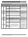
1
DS7200V2-EXP
Expert Programming Guide
EN
Control Panel
DS7200V2-EXP | Expert Programming Guide | Contents
EN | 2
Contents
1.
Introduction ...............................................................................................................................................................4
1.1
Documentation Conventions.................................................................................................................................4
1.1.1
Type Styles Used.............................................................................................................................................4
1.1.2
Notes, Cautions, and Warnings.....................................................................................................................4
1.1.3
Other Conventions .........................................................................................................................................4
2.
Scope of Document ..................................................................................................................................................4
3.
How to Program........................................................................................................................................................5
3.1
Keypad Programming ............................................................................................................................................5
3.1.1
Installer Mode/Installer Menu ......................................................................................................................5
3.1.2
Expert/Installer Programming Modes..........................................................................................................5
3.1.3
Parameter Addresses ......................................................................................................................................5
3.1.4
Text Entry Addresses .....................................................................................................................................7
3.1.5
Exit Programming Mode ...............................................................................................................................7
4.
Control Panel Programming..................................................................................................................................8
4.1
Understanding the Parameter Option Charts......................................................................................................8
4.2
Panel Wide Parameters ..........................................................................................................................................9
4.2.1
Routing Destinations ......................................................................................................................................9
4.2.2
Reporting Format Configuration.................................................................................................................10
4.2.3
Phone, Auto-Forward, and RPS Configuration .........................................................................................14
4.2.4
Global Reporting Options ...........................................................................................................................19
4.2.5
Tests................................................................................................................................................................28
4.2.6
Programming Options ..................................................................................................................................33
4.2.7
Global Open/Close Options .......................................................................................................................37
4.3
Area Wide Parameters .........................................................................................................................................48
4.4
User Interface ........................................................................................................................................................52
4.4.1
Authority Level Configuration ....................................................................................................................52
4.4.2
PIN Configuration/Installer PIN.................................................................................................................61
4.4.3
Users ...............................................................................................................................................................64
4.4.4
Keypads..........................................................................................................................................................67
4.4.5
ABC Keys and Duress Parameters .............................................................................................................71
4.4.6
RF Keypads ...................................................................................................................................................75
4.4.7
Q Button Configuration ...............................................................................................................................76
4.4.8
RF Keyfobs ....................................................................................................................................................78
4.5
Zone Parameters ...................................................................................................................................................80
4.5.1
Location Configuration ................................................................................................................................80
4.5.2
Zone Function Configuration ......................................................................................................................88
4.5.3
Global Zone Configuration........................................................................................................................103
4.6
Output Parameters ..............................................................................................................................................107
4.6.1
Global Output Configuration ....................................................................................................................107
4.6.2
Output Configuration .................................................................................................................................110
4.7
Sked Parameters..................................................................................................................................................120
4.8
Data Bus Device Parameters .............................................................................................................................123
4.8.1
RF Receiver Configuration........................................................................................................................123
4.8.2
RS-232 Module Configuration ..................................................................................................................125
4.8.3
DX8010 Telephone Module Configuration.............................................................................................126
4.8.4
DX2010 Configuration...............................................................................................................................127
4.9
Miscellaneous Programming Options ..............................................................................................................128
4.10
Network Communication ..............................................................................................................................129
4.11
DACM Configuration ....................................................................................................................................135
5.
Reference Materials .............................................................................................................................................138
5.1
Control Panel Events and Reporting Formats.................................................................................................138
5.2
Glossary................................................................................................................................................................148
Bosch Security Systems | 8/04 | 4998153891C
DS7200V2-EXP | Expert Programming Guide | Figures
EN | 3
Figures
Figure 1:
Routing Destination Phone Number Configured for Basic Pager................................................................12
Tables
Table 1:
Table 2:
Table 3:
Table 4:
Table 5:
Table 6:
Table 7:
Table 8:
Table 9:
Table 10:
Table 11:
Table 12:
Table 13:
Table 14:
Table 15:
Table 16:
Table 17:
Table 18:
Table 19:
Table 20:
Table 21:
Table 22:
Table 23:
Table 24:
Table 25:
Table 26:
Table 27:
Table 28:
Table 29:
Document Overview ...........................................................................................................................................4
Reserved and Expert Addresses.........................................................................................................................6
Key/Character Assignments ...............................................................................................................................7
Phone Number Entry Selections ........................................................................................................................9
Personal Dialing Format Configuration ..........................................................................................................11
Report Tone Selections .....................................................................................................................................11
Format Field Options ........................................................................................................................................13
Account Number Addresses/Defaults .............................................................................................................48
Account Number Entry Selections ..................................................................................................................48
User Configuration ............................................................................................................................................64
DS7446KP Keypad Icon Functions .................................................................................................................67
RF Keypad Data Bus Addresses/Transmitter Numbers................................................................................75
Location Configuration Parameters .................................................................................................................80
Default Zone Function Type Selections ..........................................................................................................84
Location Text Addresses/Defaults ...................................................................................................................86
Zone Function Configuration Parameters .......................................................................................................88
Single EOL Resistor Zone Configuration Options ........................................................................................89
Tamper-wired, Zone Doubled, and No EOL Resistor Zone Configuration Options................................89
Zone Function Type Options ...........................................................................................................................90
On-board Zone Pulse Count Time Selections ................................................................................................94
Off-board Zone Pulse Count Time Selections................................................................................................95
EOL Resistor Location Pairing for Zone Doubling .....................................................................................103
Output Configuration Parameters..................................................................................................................110
Output Function Types ...................................................................................................................................112
Output Mode Options.....................................................................................................................................117
Pulse Mode Configuration ..............................................................................................................................119
One Shot Mode Configuration.......................................................................................................................119
Sked Configuration Parameters......................................................................................................................120
Control Panel Events and Reporting Formats..............................................................................................138
Bosch Security Systems | 8/04 | 4998153891C
DS7200V2-EXP | Expert Programming Guide | 1.
1.
Introduction
1.1
Documentation Conventions
1.1.1
Type Styles Used
To help identify important items in the text, the
following type styles are used:
Bold text
Indicates important text or terms
that you should note.
Italicized text
Refers you to a drawing, table, or
other section of this document.
[9][8][7][6]
Bracketed numbers represent keypad
keys. When next to one another,
they represent the key sequence to
press for a particular function. For
this example, pressing the keys
shown enters the default Installer
PIN.
1|6
1.1.2
Numbers separated by a vertical bar
represent output function types. This
example is for Output Function
Type 1|6: Strobe.
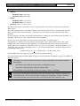
Notes, Cautions, and Warnings
Introduction
2.
EN | 4
Scope of Document
See Table 1 for an overview of this document and other
documents related to the DS7240V2/DS7220V2
Control Panels:
Table 1: Document Overview
Document
User’s Guide
Part Number
4998153894
Installer’s
Guide
4998153893
Expert
Programming
Guide (this
document)
4998153891
Release Notes
4998153890
System
Worksheet
4998153887
Throughout this document there are important notes
that address personal and/or equipment safety issues,
system operation issues, etc. They are set off as follows:
The Important Note identifies information
intended for successful operation.
The Caution Note identifies information
intended to prevent an incident that could
prohibit the functionality of the
program/equipment.
The Warning Note identifies information
intended to prevent an incident that could
prohibit the functionality of the
program/equipment and/or personal injury.
1.1.3
Other Conventions
Programming parameter titles are identified as follows:
Programming Parameter Title
Bosch Security Systems | 8/04 | 4998153891C
Description
Contains keypad
operation instructions for
the end-user. Covers use
of the LCD (text) keypad
and the LED keypad.
Contains all wiring and
setup instructions, and
basic programming
parameters with
descriptions.
Troubleshooting
information also included.
Contains all programming
parameters with
descriptions and keypad
programming
instructions.
Contains issues with
control panel that were
found after printing of the
documentation.
Contains all programming
parameter defaults and
space to record any
default changes made
during setup of the
control panel.
DS7200V2-EXP | Expert Programming Guide | 3.
How to Program
3.1.2
3.
How to Program
3.1
Keypad Programming
3.1.1
Installer Mode/Installer Menu
A text keypad such as the DS7447E or
DS7447V2 LCD Keypad can be used for
keypad programming. The DS7445i and
DS7445V2 LED Keypads cannot be used
for keypad programming.
Installer Programming Mode: Installer
Programming Mode is the control panel’s default
programming mode. This mode allows the installer
to access only a subset of the available
programming parameters. Installer Programming
Mode follows through the addresses shown in the
programming section of the DS7200V2 Installer’s
Guide (P/N: 4998153893).
•
Expert Programming Mode: When the control
panel enters the Expert Programming Mode, all of
the available programming parameters can be
accessed. This manual contains all of the available
programming parameters. Follow these steps to
enter the Expert Programming Mode:
There are three methods to access the control panel’s
programming mode. Choose a method from below and
follow its subsequent steps.
1.
Enter Installer Mode (see Installer Mode/Installer
Menu for instructions).
2.
Press [7][2][4][0][#] if you are programming a
DS7240V2. Press [7][2][2][0][#] if you are
programming a DS7220V2.
3.
Press [1][*]. The control panel enters Expert
Programming Mode, and the display shows
Address 0.
From a LCD (text) system keypad:
a. Enter the Installer’s PIN. The default Installer
PIN is 9876. See Installer PIN on page 63 for
instructions on changing the default Installer
PIN.
b. Press [#][4][1] to enter the Installer’s Menu.
c.
Press the [8] key to enter the programming
mode.
From an Installer Keypad:
d. Set the Installer Keypad address to 0 (zero).
e. Connect the Installer Keypad to the control
panel. See “Installer Keypad” in the DS7200V2
Installer’s Guide (P/N: 4998153893) for
instructions.
f.
Close the Installer Switch.
g. Enter the Installer PIN.
h. Press [#][4][1] to enter the Installer’s Menu.
i.
Press the [8] key to enter the programming
mode.
Without an Installer’s PIN:
j.
Remove all power from the control panel
(Mains and standby battery).
k.
Close the Installer Switch.
l.
Connect the Installer Keypad to the control
panel if you are using an Installer Keypad.
m. Restore all power to the control panel.
n. Locate the keypad displaying the Installer
Menu.
o. Press the [8] key.
Bosch Security Systems | 8/04 | 4998153891C
Expert/Installer Programming Modes
•
Use of the Installer PIN might be restricted.
See Keypad Response Options on page
70 for information on enabling/restricting
the Installer PIN.
1.
EN | 5
3.1.3
Parameter Addresses
Data for each parameter is stored at one or more
addresses. Special addresses identified as option
parameters allow you to set several options at a single
address.
There are two parts to every address displayed across
the keypad’s top line:
•
Adr: XXXX: The number following “Adr”
indicates the current address displayed.
•
D=X: “X” indicates the data digit selection for the
address currently displayed.
Adr: 0000
D=0
To view a specific address, enter the 4-digit address
number and then press [#].
For example, to go to Address 0221, press the
following keys in this order: [0][2][2][1][#].
Leading zeroes can be omitted. Pressing [2][2][1][#] is
the same as pressing [0][2][2][1][#].
Adr: 0000
D=0
0221
To scroll forward one address at a time, press [#]. To
scroll back one address at a time, press [*].
DS7200V2-EXP | Expert Programming Guide | 3.
Follow these steps to edit the data digit entry for an
address:
How to Program
EN | 6
1.
Enter the address.
Certain addresses are skipped during keypad
programming: Reserved addresses and Expert
addresses. Table 2 identifies these addresses.
2.
Press the [#] key.
•
3.
Enter the new value (0 to 15).
Reserved Addresses: These addresses are
reserved for future development.
4.
Press the [*] key.
•
Expert Addresses: These addresses are only
available when the control panel enters Expert
Programming Mode.
For example, to change the data digit for Address 0221
from 0 to 1, press the following keys in this order:
[1][*]. The new value appears on the second line of the
display.
Adr: 0221
D=0
Keypad display before making any
changes. Current Data Digit entry
shown.
↓
Adr: 0221
D=0
Press [1] to change Data Digit entry
from 0 to 1.
D=1
Press [*] to accept new Data Digit
entry. Display updates new entry.
1
↓
Adr: 0221
Follow these steps to fix an incorrect data digit entry:
1.
Press the [#] key.
2.
Re-enter the address you wish to program.
3.
Press the [#] key.
4.
Enter the desired data digit value (0 to 15).
5.
Press the [*] key.
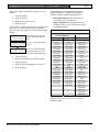
Table 2: Reserved and Expert Addresses
Reserved Addresses
DS7240V2
DS7220V2
0214-0219
0214-0219
0237
0237
0274-0275
0274-0275
0282-0285
0282-0285
0292-0295
0292-0295
0304-0307
0304-0307
0314-0317
0314-0317
0326-0329
0320-0363
0336-0339
0826-0905
0348-0351
1035-1037
0358-0361
1128-1183
1035-1037
1252
1252
1262
1262
1522-1649
2940-2943
2418-2929
2945-3405
2940-2943
3430-3433
2945-3405
3434-3441
3430-3433
3442-3505
3434-3441
3541-3545
3442-3505
3554-9999
3541-3545
3554-9999
Expert Addresses
0065
0132-0180
0222-0236
0238-0248
0255-0257
0260
0262-0273
0297
0319
0341
0363-0378
0703
0906-1034
1038-1043
1251
1253-1261
1263-1265
2930-2939
2944
3406-3413
3507-3513
3515-3521
3523-3529
3531-3537
3539-3540
3886-3910
Press [#] to move forward to the next available
address. Press [*] to move back to the previous
available address.
Bosch Security Systems | 8/04 | 4998153891C
DS7200V2-EXP | Expert Programming Guide | 3.
3.1.4
Text Entry Addresses
All text entry addresses (System Text, Area Text and
Location Text) require the use of a special textprogramming mode. In this mode, the keypad keys
display different characters depending on the number
of times the keys are pressed. See Table 3.
A character’s order in the character selection sequence
indicates the number of key presses necessary to
produce the character. For example, pressing the [2]
key four times produces “a.”
Table 3: Key/Character Assignments
Key
0
1
2
3
4
5
6
7
8
9
*
#
A
C
Character
+-0*/\[]=><#§
Space . 1 ? ! , @ _ & ~ : ; " ( ) ' ¿ ¡ % £ $ ¥
ABCabc2ÅÄÃåäáàâãαβÇç
DEFdef3ÉÆëéèêæ∆Φδε
GHIghI4ïíîìΓγηι
JKLjkl5Λκλ
MNOmno6ÖöÑñØÕøóòôõΩµνω
PQRSpqrs7ΠΣπρσ
TUVtuv8ÜüúùûΘΥθτυ
WXYZwxyz9ÿΞΨξχψζ
Moves to the address before the text block.
Moves to the address after the text block.
Moves cursor to the previous character position in
text block.
Moves cursor to the next character position in text
block.
Bosch Security Systems | 8/04 | 4998153891C
How to Program
EN | 7
The following keys are not used in text programming
and produce an error tone when pressed:
•
[B]
•
[On]
•
[Off]
•
[Perimeter Only]
•
[No Entry]
•
[Bypass]
•
[System Reset]
Press [1] once to clear a character space
or to enter a blank space.
3.1.5
Exit Programming Mode
Press and hold [#]. The LCD keypad displays the
control panel’s model number and firmware revision
number on the top line, and “Please Wait...” on the
bottom line. This message remains for approximately
10 sec.
To reduce the occurrence of false alarms at
power-up (or restoration of power after a
complete loss of primary and secondary
power) or upon exiting programming mode,
the control panel ignores all zone alarms for
approximately 60 sec while the devices
stabilize.
DS7200V2-EXP | Expert Programming Guide | 4.
4.
Control Panel Programming
EN | 8
Control Panel Programming
The contents of this section are organized as in Remote Programming Software (RPS).
This section covers all of the available programming parameters. The programming section in the
DS7200V2 Installer’s Guide (P/N: 4998153893) covers the programming parameters only available
when the control panel is in the Installer Programming Mode.
This section contains programming parameter information pertaining to the DS7240V2 and DS7220V2 Control
Panels. Settings for parameters are stored at one or more addresses. For an overview of how to program the
control panel from a DS7447E or DS7447V2 Text Keypad, see Keypad Programming on page 5.
Numbers enclosed in braces, (for example, {137}) that appear throughout this document refer to the control
panel’s event numbers. See Control Panel Events and Reporting Formats on page 138 for event descriptions.
The default Installer PIN is 9876. The default PIN for User 1 is 1234. All other user PINs are not programmed by
default. See Installer PIN on page 63 and PIN, User # on page 65 for more information.
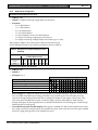
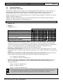
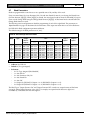
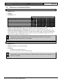
4.1
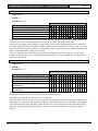
Understanding the Parameter Option Charts
The programming section of this document uses charts like the one below to identify the available selections for
option parameters.
Phone Line Options
No Phone Line Options
Do Not Wait for Dial Tone
“R” Function/Three-way Calling
Reserved
0
1
Enter This Data Digit to Select Options
2 3 4 5 6 7 8 9 10 11 12 13 14 15
•
•
•
•
•
•
Phone Line Fault Requires Reset
•
•
•
•
•
•
•
The first option usually disables or turns off all the other options.
The data digit values (labeled 0 to 15 under the “Enter This Data Digit to Select Options” heading) are displayed
across the top of the table. Each data digit is ties to options by a “•.” To select an option, enter the corresponding
data digit value at the address programming prompt.
The option parameter’s default selection is listed above the table in bulleted form along with the option’s address
and selection range. The numbered cell that corresponds with the option’s default setting is blackened to provide a
quick visual reference. For example, the cell labeled “10” in the example above is this option parameter’s default.
Columns that are grayed out are reserved settings and should not be selected.
Bosch Security Systems | 8/04 | 4998153891C
DS7200V2-EXP | Expert Programming Guide | 4.
4.2
Panel Wide Parameters
4.2.1
Routing Destinations
Control Panel Programming
EN | 9
The control panel has two routing destinations for the routing of reports. The control panel routes by zone and
report group to the destinations. For example, you can send alarm reports for one zone to Destination 1 and for
another zone to Destination 2.
You can program two phone numbers (or IP addresses) for each destination.
Communication Fail events are by destinations and not by phone number/IP address.
For a description of the routing/dialing process, see “Dialing Attempt Tables” in the DS7200V2 Installer’s Guide
(P/N: 4998153893).
Phone Number 1 (2) for Destination 1 (2))
•
Address Range:
−
−
−
−
Phone 1, Destination 1: 0000 to 0031
Phone 2, Destination 1: 0032 to 0063
Phone 1, Destination 2: 0066 to 0097
Phone 2, Destination 2: 0098 to 0129
•
Default: All zeroes (0)
•
Selections: 0 to 14 (see Table 4)
Table 4: Phone Number Entry Selections
Digit to be Dialed
1
2
3
4
5
6
7
8
Enter at Keypad
1
2
3
4
5
6
7
8
Digit to be Dialed
9
0
*
#
P (4-sec pause)
F (on-hook, pause, off-hook)
Reserved
T (Terminate)
Enter at Keypad
9
10
11
12
13
14
15
0
When entering phone numbers, enter “10” ([1][0] from the keypad) to dial “0”; enter “0” to terminate
the phone number. This does not apply when entering an IP address.
Terminate telephone numbers with less than 32 digits by entering a zero (0) in the Address after the
last digit to be dialed.
The control panel can dial up to 32 digits per phone number. Each digit occupies one address. If less than 32
digits are entered into the Phone Number Address range, the control panel dials digits until it reaches a terminator
(0).
IP addresses can be entered into these addresses for network communication. See Network Communication on page
129 for more information. Firmware revision 2.10 or greater is required for network communication.
See Area # Account Number on page 48 for instructions on entering an account number.
Bosch Security Systems | 8/04 | 4998153891C
DS7200V2-EXP | Expert Programming Guide | 4.
Control Panel Programming
EN | 10
Format for Destination 1 (2)
•
Address:
−
−
Format for Destination 1: 0064
Format for Destination 2: 0130
•
Default: 2 (Contact ID)
•
Selections: 2 to 4, 7, 11
−
−
−
−
−
2 = Contact ID
3 = SIA 300
4 = Basic Pager
7 = Personal Dialing Format
11 = SIA 300 with Text Blocks
This parameter selects the reporting format. All reports for this destination are sent in the format chosen here.
If you configure the control panel for network communication, you must set this parameter to Contact ID. See
Network Communication on page 129 for more information. Firmware revision 2.10 or greater is required for
network communication.
Check communications from control panel to Alarm Receiving Center (ARC) to verify that the control
panel is communicating properly in the selected reporting format.
4.2.2
Reporting Format Configuration
Personal Dialing Format
Select the Personal Dialing Format by entering “7” into the appropriate reporting format address. See Format for
Destination 1 (2) on page 10 for more information. The control panel calls a phone number where a person is
expected to answer.
The control panel starts by placing a phone call. The control panel then sends the first digit of the report, waits
one second, and then sends the second digit of the report. The control panel then waits three sec, and sends the
report again. The control panel continues to repeat the report for a total of ten times. Some reports have zero as
the second digit. In these cases, only the first digit is sent, the control panel waits approximately three sec, and
then the report is repeated.
During the three-second delay between each report, pressing [5] on the phone’s keypad acknowledges the report.
The control panel advances to the next event in the dialer queue and sends it in the same phone call, or hangs up
if there are no more events to report. The control panel send each report up to ten times or until it is
acknowledged.
If no one acknowledges the report after ten tries, the control panel hangs up and calls again. If two phone
numbers are programmed for the destination, the second phone number is called. The control panel follows the
normal event phone routing. For each event, the control panel tries five times or until the event is acknowledged.
If no acknowledge is received in the five phone calls, the control panel logs a communication failure for the
destination.
The control panel divides all possible events into Event Groups as reported to RPS. This event group selects
which report to send. The event groups are numbered 1 to 16. The following table lists the 16 possible event
groups. Table 31 details all events generated by the control panel. Not all events are transmitted in Personal
Dialing Format.
Bosch Security Systems | 8/04 | 4998153891C
DS7200V2-EXP | Expert Programming Guide | 4.
•
Address: See Table 5
•
Default: See Table 5
•
Selections: 0 to 15
Control Panel Programming
EN | 11
Table 5: Personal Dialing Format Configuration
Event Group
1
2
3
4
5
6
7
8
9
10
11
12
13
14
15
16
Address
3414
3415
3416
3417
3418
3419
3420
3421
3422
3423
3424
3425
3426
3427
3428
3429
Personal Dialing Format Code
Duress
Fire Alarm
Non-fire Alarm
Reserved
Fire Trouble
Non-fire Trouble
Fire Restoral
Non-fire Restoral
RF Trouble
Open/Close
Installer Mode
System Fault
Test Report
Reserved
Bypass
Output/User
Data Digit Default
0
1
2
0
5
6
0
0
0
0
0
8
0
0
0
0
Use this parameter to select the tone for the 16 different Personal Dialing Format event groups.
For each event group, the report is programmed as a value from 0 to 15. If 0 (zero) is programmed, no report is
sent and the event is a Local Only event.
See Table 6 for the two-digit report tone when the value entered is non-zero (1to15).
Table 6: Report Tone Selections
Data Digit Selection
0
1
2
3
4
5
6
7
8
9
10
11
12
13
14
15
Report Tone
None
10
11
20
12
21
30
13
22
31
40
14
23
32
41
50
Bosch Security Systems | 8/04 | 4998153891C
DS7200V2-EXP | Expert Programming Guide | 4.
Control Panel Programming
EN | 12
For example, if Data Digit Selection “5” is entered, the following report tone is transmitted (“-“ equals 1 beep): -- -.
There is a 1-second pause between the transmission of the first digit and the second digit. The second digit is
followed by a 3-second pause.
The control panel repeats the report for a total of ten times (-- - -- - -- - -- - -- - -- - -- - -- - -- - -- -)
SIA 300 with Text Blocks
The control panel sends reports using the SIA format when “3” is entered into the appropriate reporting format
address. See Format for Destination 1 (2) on page 10 for more information. An additional format (selection of “11”)
is available to include ASCII text with the SIA event codes.
If the SIA event includes a zone number as one of its parameters, and the zone represents one of the control
panel’s 40 locations, the control panel sends the zone’s programmable location text (see Location ##, Zone Text on
page 86 for more information). The event (N) block is sent first followed by the text (A) block. If there is no zone
number for the event, then no ASCII text is reported.
Basic Pager Display
Setting a Routing Destination to Basic Pager format configures the control panel to send reports to a numeric
pager. Follow these steps to use the Basic Pager format:
1.
2.
Enter the phone number for the pager in the “Phone Number 1” parameter for the Routing Destination you
have chosen as the Basic Pager Destination.
Set the “Format for Destination 1 (2)” parameter to Basic Pager for the Routing Destination you have chosen
as the Basic Pager Destination.
Set the routing for any reports you would like sent to the pager to the Routing Destination (1 or 2) you have
chosen as the Basic Pager destination.
Report digits are dialed as 100-ms DTMF tone pulses with 100-ms pauses between the digits.
The control panel’s Basic Pager format does not wait for an acknowledgement tone from the pager
service provider to send its report to the pager. It dials the phone number, waits 250 ms and then sends
the report. To increase the delay (pause), add delay characters as needed to the end of the phone
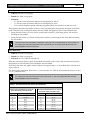
number. See Table 4 on page 9 for the valid phone number entries.
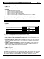
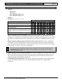
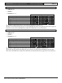
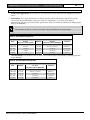
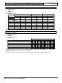
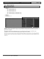
All information the control panel needs to format and send events to a pager is contained in Phone Number 1 (2) for
Destination 1 (2) on page 9. Figure 1 shows the phone number broken into fields.
Figure 1: Routing Destination Phone Number Configured for Basic Pager
1234-
5 5 5 1 2 3 4 P P
0
* * *
0
# 9
0
1
2
3
2
4
2
Digits to Dial Field: Enter the phone number for the paging service followed by any special characters
required (a pause, for example). See Table 4 on page 9for phone number entries.
Field Terminator: Every field must end with the terminator digit, always 0 (zero).
Format Field: Use this field to configure how the message appears in the pager’s display. See Table 7 on
page 13 for Format Field options.
End Page Field: Enter the digits that tell your paging service you are done sending your page.
The control panel dials the number you enter in the Digits to Dial Field to contact the paging service. Add one
or more pauses at the end of the number to allow the paging service time to answer the phone and prepare to
accept the message. The Digits to Dial Field ends with a Field Terminator (0).
The Format Field follows the Digits to Dial Field. It defines what information follows the account number in the
paging message. The Format Field ends with a Field Terminator (0).
Bosch Security Systems | 8/04 | 4998153891C
DS7200V2-EXP | Expert Programming Guide | 4.
Control Panel Programming
EN | 13
The End Page Field follows the Format Field. The digits you enter in this field are sent after the paging
message. For many paging services, a ‘#’ indicates the end of the paging message. The End Page Field ends with
a Field Terminator (0).
You must enter the pauses required for the paging service in the Digits to Dial Field before the Digits
to Dial field terminator.
The number of pauses required varies based on the paging service.
Test the pager to determine that you entered enough pauses to establish communications to the
paging service.
Table 7: Format Field Options
Format Field
Empty
#
***
#***
**
#**
*
Resulting Pager Display
Account, Event, Area, and Zone Numbers
with separator characters
Account, Event, Area, and Zone Numbers
without separator characters
Account, Event, and Area Numbers with
separator characters
Account, Event, and Area Numbers without
separator characters
Account and Event Numbers with separator
characters
Account and Event Numbers without
separator characters
Account Number only
1234-008-03-21
12340080321
1234-008-03
123400803
1234-008
1234008
1234
If the zone/user number is three digits, the leading digit is omitted. For example, “252” displays as
“52.”
Do not use alpha characters for the account number in basic pager format.
Bosch Security Systems | 8/04 | 4998153891C
DS7200V2-EXP | Expert Programming Guide | 4.
4.2.3
Control Panel Programming
EN | 14
Phone, Auto-Forward, and RPS Configuration
Integral Voice Verification Module
•
Address: 0065
•
Default: 0
•
Selections:
−
−
0 = Disable Voice Verification
1 to 15 = Enable the Voice Verification Module and identify which output is the Voice Request output in
Area 1
This parameter enables the voice verification module. Program one of the first 15 outputs as Output Function
Type 2|10 “Voice Request.” Enter that output number (1 to 15) in this parameter. See Function, Output ## on page
112 for more information.
Set this address to 0 if the integral voice verification module is not installed.
Phone Line Options
•
Address: 0131
•
Default: 0
•
Selections: 0 to 3, 8 to 11
Phone Line Options
No Phone Line Options
Do Not Wait for Dial Tone
“R” Function/Three-way Calling
Reserved
Phone Line Fault Requires Reset
0
1
Enter This Data Digit to Select Options
2 3 4 5 6 7 8 9 10 11 12 13 14 15
•
•
•
•
•
•
•
•
•
•
•
•
•
This parameter consists of three options for the physical phone line.
•
Do Not Wait for Dial Tone: If this option is enabled, the control panel waits three sec after going off-hook
and then starts dialing. If this option is disabled, the control panel waits up to seven sec for a dial tone. The
control panel dials when it detects the dial tone.
•
“R” Function/Three-way Calling: If this option is enabled, the control panel’s “R” function/three-way
calling feature is enabled. The phone company must enable this option on the control panel’s telephone line.
•
Phone Line Fault Requires Reset: If this option is enabled and a phone line fault occurs, the trouble
condition (keypad trouble message and/or tone) continues until the [System Reset] key is pressed (fix the
phone line fault first). If this option is not disabled and a phone line fault occurs, the trouble condition clears
automatically when the phone line fault is corrected. This option also applies to the Alternate Communication
Path Fault Control Input (see Options 1 for Zone Function Type 3 (24-hr Control Input) on page 97).
Bosch Security Systems | 8/04 | 4998153891C
DS7200V2-EXP | Expert Programming Guide | 4.
Control Panel Programming
EN | 15
DTMF/Pulse Dialing
•
Address: 0132
•
Default: 0 (DTMF)
•
Selections:
−
−
0 = DTMF
1 = Pulse
This parameter selects the control panel dialing format (DTMF or Pulse). This format is used for all dialing
attempts.
Call Forwarding Auto On/Off Digits
•
Address:
−
−
Call Forwarding Auto On Digits: 0133 to 0164
Call Forwarding Auto Off Digits: 0165 to 0180
•
Default: All zeroes (0)
•
Selections: See Table 4 on page 9
−
−
Call Forwarding Auto On Digits: Up to 32 characters max
Call Forwarding Auto Off Digits: Up to 16 characters max
This parameter configures the control panel’s Call Forwarding Auto On/Off operation.
In order to use this parameter, the premises must have Call Forwarding service from the local
telephone company. Call Forwarding Auto On/Off does not forward calls; it turns the telephone
company’s Call Forwarding service on or off by dialing digits just as the user would.
When entering phone numbers, use “10” ([1][0] from the keypad) to enter “0”; use “0” to terminate the
phone number.
Call Forwarding Auto On/Off is only available for Area 1.
If Call Forwarding Auto On/Off is enabled ([#][8][2]) and a user turns the system All On, the control panel dials
the Call Forwarding Auto On digits to activate the telephone company’s Call Forwarding service.
If Call Forwarding Auto On/Off is enabled ([#][8][2]) and a user turns the system off (from All On), the control
panel dials the Call Forwarding Auto Off digits to turn off the Call Forwarding service.
•
A typical dialing sequence might be:
•
Two-digit telephone company code (*21*)
•
Pause
•
Phone number to forward to (Example: 555-1212)
•
Flash (on-hook, pause, off-hook)
•
Terminate (t)
For this sequence, the entry at this parameter is *2 1 * p 5 5 5 1 2 1 2 f t.
See the DS7200V2 User’s Guide (P/N: 4998153894) for more information on Call Forwarding Auto On/Off.
Bosch Security Systems | 8/04 | 4998153891C
DS7200V2-EXP | Expert Programming Guide | 4.
Control Panel Programming
EN | 16
Remote Programming Call Back Number
•
Address: 0181 to 0212
•
Default: All zeroes (0)
•
Selections: See Table 4 on page 9
The control panel dials this phone number (or IP address) to begin a RPS remote programming session. See
Network Communication on page 129 for complete network communication programming instructions. Firmware
revision 2.10 or greater is required for network communication.
There are three ways to use this phone number (or IP address):
1.
RPS calls the control panel, which answers and determines it is RPS calling, then it disconnects and calls
RPS back.
2.
When a user presses [#][4][3], the control panel calls RPS using the phone number (or IP address) entered
here.
3.
The control panel can be programmed to use this phone number (or IP address) automatically at test
report time (see Automatic Test {137} Report Options on page 31 for more information).
When entering phone numbers, enter “10” ([1][0] from the keypad) to dial “0”; enter “0” to terminate
the phone number. This does not apply when entering an IP address.
Bosch Security Systems | 8/04 | 4998153891C
DS7200V2-EXP | Expert Programming Guide | 4.
Control Panel Programming
EN | 17
RPS Answer Ring Count, Answering Machine Bypass
•
Address: 0213
•
Default: 7 (rings)
•
Selections:
−
−
−
−
0 = Control panel does not answer phone
1 to 13 = Ring Count
14 = Answering Machine Bypass 1
15 = Answering Machine Bypass 2
The ring count sets the number of rings the control panel waits before picking up and seizing the phone line for a
remote programming session, or for remote arming with a telephone (see Arming Options 1 on page 37).
The control panel does not answer the phone for remote programming or remote arming with telephone when
this parameter is set to zero (0).
This ring count is used for any control panel arming state, armed or disarmed.
The Answering Machine Bypass function can be restricted to only operate when the system is armed All On or
Perimeter Only (see Arming Options 1 on page 37). When the Answering Machine Bypass function is restricted to
only operate when the system is armed All On or Perimeter Only, the control panel does not answer the phone
for a remote arming session when it is disarmed (Off). However, [#][4][3] still initiates a remote programming
session.
Answering Machine Bypass 1
1.
Call the premises; let the phone ring no more than two (2) times. Then hang up/disconnect the remote
programmer.
2.
Wait at least eight sec to call back, but call back within 45 sec.
3.
The control panel then picks up after the first ring.
Answering Machine Bypass 2
1.
Call the premises; let the phone ring no more than four (4) times. Then hang up/disconnect the remote
programmer.
2.
Wait at least eight sec to call back, but call back within 45 sec.
3.
The control panel then picks up after the first ring.
Bosch Security Systems | 8/04 | 4998153891C
DS7200V2-EXP | Expert Programming Guide | 4.
Control Panel Programming
EN | 18
Phone Line Fault Response Options
•
Address: 0220
•
Default: 0
•
Selections: 0, 1, 3, 5, 7
Phone Line Fault Response Options
No Phone Line Supervision
Enable Supervision (System Trouble at Keypad)
Burg Alarm & Strobe Functions, All On/Perimeter
Only
Burg Alarm & Strobe Functions, Off
0
1
Enter This Data Digit to Select Options
2 3 4 5 6 7 8 9 10 11 12 13 14 15
•
•
•
•
•
•
•
•
•
Reserved
The control panel monitors the phone line for voltage only. If the voltage drops low enough (between 1 and 3 V)
for 40 sec, it declares a phone line fault. If the phone line voltage remains above 3 V for at least 40 sec, it declares
the phone line restored. See the ”Phone Line Fault Requires Reset” option in Phone Line Options on page 14.
When enabled, the Phone Line Fault event appears at all keypads for all areas. The control panel sends a Phone
Line Restore {100} report when a phone line fault event restores.
If the phone line fails (as described above), but restores before a Comm Fail event:
1.
System detects phone line fail and puts Event {99} in the log.
2.
System starts dialing attempts if programmed for Phone Fail report.
3.
Phone line restores before Comm fail event.
4.
System sends phone line fail and phone line restore reports.
If the phone line fails (as described above), but restores after a Comm Fail event:
1.
System detects phone line fail and puts report in the event in the log.
2.
System starts dialing attempts if programmed for Phone Fail report.
3.
Dialing attempts end with Comm fail event, phone fail report is flushed.
4.
System detects phone line is restored and puts restoral report in buffer.
5.
System starts dialing attempts and sends phone fail restoral and Comm restoral reports.
If an alternate communication path is enabled, the control panel can send a Phone Line Fail {99} report via the
alternate communication path when a phone line fault event occurs.
•
No Phone Line Supervision: If this option is enabled, the control panel does not monitor the phone line
voltage. Phone Line Fault events do not appear at keypads. The other Phone Line Fault Response options are
also disabled if No Phone Line Supervision is selected.
•
Enable Supervision (System Trouble at Keypad): If this option is enabled, the keypad displays a phone
line trouble message if a phone line fault occurs as described above. To enable the keypad to sound a trouble
tone on system troubles, see Keypad # Options on page 67 for details.
•
Burg Alarm & Strobe Functions, All On or Perimeter Only: If this option is enabled, the system’s burglary
alarm and strobe function as configured when the system is armed All On or Perimeter Only if a phone line
fault occurs as described above. See Output Parameters on page 107 for burglary alarm/strobe output
configuration.
•
Burg Alarm & Strobe Functions, Off: If this option is enabled, the system’s burglary alarm and strobe
function as configured when the system is off (not armed) if a phone line fault occurs as described above. See
Output Parameters on page 107 for burglary alarm/strobe output configuration.
Bosch Security Systems | 8/04 | 4998153891C
DS7200V2-EXP | Expert Programming Guide | 4.
4.2.4
Control Panel Programming
EN | 19
Global Reporting Options
These parameters configure the reporting for all areas, all zones, and all users.
Global Reporting Options
•
Address: 0221
•
Default: 1
•
Selections: 0, 1, 3, 5, 7, 9, 11, 13, 15
Global Reporting Options
Local Only
Enable Reporting
Extend Handshake
Delay Alarm Output
Burg Alarm after Two Failed Attempts
0
1
Enter This Data Digit to Select Options
2 3 4 5 6 7 8 9 10 11 12 13 14 15
•
•
•
•
•
•
•
•
•
•
•
•
•
•
•
•
•
•
•
•
•
•
Local Only: The control panel sends no reports.
•
Enable Reporting: If this option is enabled, the control panel sends reports as programmed provided that at
least one phone number (or IP address) has been programmed for at least one Routing Destination (see Phone
Number 1 (2) for Destination 1 (2) on page 9). Reporting options can be enabled and disabled in other
parameters. See Open/Close Reporting Options on page 39, and Area # Opening {89-96}/Closing {42-67} Reporting
Options on page 49 for more information.
•
Extend Handshake: If this option is enabled, the control panel finishes dialing the ARC receiver and waits
for a ‘handshake’ tone from the receiver. The handshake is the first thing the receiver sends after answering
the phone. Typically each reporting format the receiver supports has its own handshake tone. If a receiver
supports several formats, it sounds the handshake tones one at time. Choosing this option extends the time the
control panel waits for a handshake from the ARC receiver from 45 to 60 sec.
Do not change the Extend Handshake option unless advised by Bosch Technical Service.
•
Delay Alarm Output: If this option is enabled, the control panel delays burglary alarm output until
communication to the ARC receiver is complete or there are two failed dialing attempts. The delayed alarm
output functions are 1|8, 1|9 and 1|10 (see Table 25 on page 112 for descriptions of output function types). Bell
Time is not delayed, and begins at the alarm event. If Bell Time is set at three min. or less, alarm output
delayed by this option may be very short (less than 1 minute), or the alarm output may not activate at all. See
Output Parameters on page 107 for a complete description of output functions. The keypad sounder is not
delayed by this option.
Disable the Alarm Event Abort option when using the Delay Alarm Output option. See Options 1, Zone
Function ## on page 95.
Bosch Security Systems | 8/04 | 4998153891C
DS7200V2-EXP | Expert Programming Guide | 4.
•
Control Panel Programming
EN | 20
Burg Alarm After Two Failed Attempts: If this option is enabled, a steady alarm output sounds after two
failed attempts to transmit a burglary alarm report from any zone when its area is armed. Alarm output is
provided even if the zone is not programmed for alarm output. Program Bell Time to at least 3 min. when
using this option. Disable this option if you want to prevent an alarm output from silent zones even when the
system fails to communicate with the receiver. This option only applies to the following output function types:
−
1|8 Alarm: All On, Perimeter Only, and Partial On (Non-Fire 24-hr alarms)
−
1|9 Alarm: Perimeter Only and Partial On Modes (Non-Fire 24-hr alarms)
−
1|10 Alarm: Controlled Zones and 24-hr Zones (Fire and Non-Fire)
See Output Parameters on page 107 for alarm configuration.
The burg alarm output activates after two failed communication attempts even if the zone is set for
silent operation.
Ack Wait Time
•
Address: 0222
•
Default: 5 (5 sec)
•
Selections:
−
−
0 = 1 second
1 to 15 = 1 to 15 sec (1-second increments)
This parameter sets the amount of time the control panel waits for an acknowledgment tone from the ARC
receiver.
Do not change the default value unless advised by Bosch Technical Service.
Bosch Security Systems | 8/04 | 4998153891C
DS7200V2-EXP | Expert Programming Guide | 4.
Control Panel Programming
EN | 21
AC Power Supervision Options
•
Address: 0223
•
Default: 4
•
Selections: 0 to 15
AC Power Supervision Options
No Options Selected
AC Fail Report is Tag-along
Disable AC Fail Local Annunciation (at keypad)
Enable Arm/Disarm/Bypass Tracking
Enable Internal Crystal to Keep Time
0
1
Enter This Data Digit to Select Options
2 3 4 5 6 7 8 9 10 11 12 13 14 15
•
•
•
•
•
•
•
•
•
•
•
•
•
•
•
•
•
•
•
•
•
•
•
•
•
•
•
•
•
•
•
•
•
This parameter configures the control panel’s local response to AC power failure.
AC power must be failed for a maximum of 10 sec before the control panel responds to the failure. It must be
restored for a maximum of 10 sec before the control panel responds to the AC restoral. See AC Fail Report Delay
on page 34 for instructions on delaying the AC Fail Report.
The trouble tone for AC fail events sounds at all keypads in all areas. However, the trouble tone must be
silenced in each area. Silencing the trouble tone in one area does not silence it in the other areas.
•
AC Tag-along: If this option is enabled, AC Fail and Restoral reports are not sent at the time of the event,
but are sent as ‘tag-along’ reports with the next report to be sent.
•
Disable AC Fail Local Annunciation (at Keypad): If the control panel is only powered from a DC power
source (through battery connections), select Option 2, “Disable AC Fail Local Annunciation.” This prevents
the control panel from annunciating AC failures locally at the keypad. You must also disable AC Fail
reporting at the next parameter, “AC Fail, Low Battery Report Options.”
•
Enable Arm/Disarm/Bypass Tracking: If If this option is not enabled, the control panel always powers up
in the disarmed state (Off), even if the control panel was armed before powering down. Zones that were
bypassed before powering down are not bypassed at power-up.
•
Enable Internal Crystal to Keep Time: Not enabling this option keeps time by looking at the Mains AC
power. Enable this option if running on DC only (for example, if you are generating your own power or
power cycles are not consistent), otherwise leave set to default.
Bosch Security Systems | 8/04 | 4998153891C
DS7200V2-EXP | Expert Programming Guide | 4.
Control Panel Programming
EN | 22
AC Fail {1}/Low Battery {22} Report Options
•
Address: 0224
•
Default: 7
•
Selections: 0 to 15
AC Fail, Low Battery Reporting Options
No AC Fail Reports, No Low Battery Reports
AC Fail Reports
AC Restoral Reports
Low & Missing Battery and Restoral Reports
Ground Fault and Restoral Reports
0
1
Enter This Data Digit to Select Options
2 3 4 5 6 7 8 9 10 11 12 13 14 15
•
•
•
•
•
•
•
•
•
•
•
•
•
•
•
•
•
•
•
•
•
•
•
•
•
•
•
•
•
•
•
•
•
AC Fail, Low Battery and Ground Fault events occur at all keypads for all areas. This parameter enables reporting
of AC power and battery supervision events, and ground fault events.
Enable reporting at the Global Reporting Options parameter (see Global Reporting Options on page
19), and enter at least one phone number (or IP address) for one routing destination (see Phone
Number 1 (2) for Destination 1 (2) on page 9).
The battery is considered low if the nominal voltage on its terminals drops below 12.1 V. The low battery is
considered missing if the nominal voltage on its terminals drops below 10.2 V.
System Status Report Swinger Count
•
Address: 0225
•
Default: 0 (Disabled)
•
Selections:
−
−
0 = Disabled
1 to 15
Set this parameter to zero (0) to disable the System Status Report Swinger. System Status reports are sent as they
occur.
Entering a value from 1 to 15 enables System Status Report Swinger and sets the swinger count. Each system
status report has its own swinger counter. When the count is reached that report is no longer transmitted during
the arming cycle.
For example, if you entered 1 at this parameter, the control panel would only transmit one AC fail report, no
matter how many times AC failed and restored during the arming cycle.
Not all System Status Reports follow this Swinger Count. System Status reports that follow the count set in this
parameter are marked with an “S” in Table 31 (see page 138).
To reset the System Status Report Swinger Count, arm and then disarm the control panel.
Bosch Security Systems | 8/04 | 4998153891C
DS7200V2-EXP | Expert Programming Guide | 4.
Control Panel Programming
EN | 23
System Status Report Routing
•
Address: 0226
•
Default: 1 (Reports to Destination 1, Events to Log/Printer)
•
Selections:
−
−
−
−
−
−
0 = No Reports, no Events to Log/Printer
1 = Reports to Destination 1, Events to Log/Printer
2 = Reports to Destination 2, Events to Log/Printer
3 = Reports to Destinations 1 & 2, Events to Log/Printer
4 = Reports to Destination 2 only on Destination 1 Comm Fail Event, Events to Log/Printer
5 = No reports, Events to Log/Printer
System Status reports routed by this parameter are marked with an “R” in Control Panel Events and Reporting
Formats on page 138.
Comm Fail 1 (2) reports follow System Status Reports routing. Comm Fail reports for either destination are only
sent if the other destination is the System Status Reports destination. See “Communication Failure (Comm Fail)”
for a description of the Comm Fail event, and “Dialing Attempt Tables” for the dialing sequence in the DS7200V2
Installer’s Guide (P/N: 4998153893).
Call for Service Interval
•
Address: 0227, 0228
•
Default: 0,0
•
Selections: 00 to 99
This parameter determines the interval in weeks (7 days), (00 to 99). For example, if you enter 0,2, the control
panel waits 2 weeks (14 days) between displaying service messages.
At this interval, the keypad displays a “Call for Service” fault and/or sends a Call for Service {37} report (per the
Call for Service/System Inactive Options parameter). The display appears at all keypads in all areas. The report is sent
for Area 1 only and follows System Status Report routing.
Press [System Reset] to reset the fault in the area to which the keypad is assigned. Enter 0,0 to disable this
parameter.
System Inactive Interval
•
Address: 0229, 0230
•
Default: 0,0
•
Selections: 00 to 99
If an area is not armed (All, Perimeter Only or Partial On) in this interval, the control panel sends a System
Inactive {136} Report for that area. A ‘System Inactive’ Display is optional, see Call for Service/System Inactive
Options on page 24 for more information.
The interval is in weeks (00 to 99). Enter 0,0 to disable this parameter.
Bosch Security Systems | 8/04 | 4998153891C
DS7200V2-EXP | Expert Programming Guide | 4.
Control Panel Programming
EN | 24
Call for Service/System Inactive Options
•
Address: 0231
•
Default: 0
•
Selections: 0 to 15
Call for Service/System Inactive Options
No Options
Call for Service Display at Call for Service
Interval
Call for Service Report at Call for Service
Interval
Call for Service Display at System Inactive
Interval
Enable Weekly Test Reminder
0
1
Enter This Data Digit to Select Options
2 3 4 5 6 7 8 9 10 11 12 13 14 15
•
•
•
•
•
•
•
•
•
•
•
•
•
•
•
•
•
•
•
•
•
•
•
•
•
•
•
•
•
•
•
•
•
•
Call for Service Display at Call for Service Interval: If this option is enabled, the keypad displays a “Call
for service” trouble at all keypads in all areas and/or sends a report for Area 1 at the Call for Service Interval.
Press the [System Reset] key to reset the fault in the area to which the keypad is assigned. There is no trouble
tone for the Call for Service Interval event.
•
Call for Service Report at Call for Service Interval: If this option is enabled, the Call for Service {37}
Report follows System Status routing. The interval is in weeks (00 to 99). See Call for Service Interval on page
23.
•
Call for Service Display at System Inactive Interval: If this option is enabled, the keypad displays a “Call
for Service” trouble at all keypads and/or sends a System Inactive {136} report for that area at the System
Inactive Interval. See System Inactive Interval on page 23.
•
Enable Weekly Test Reminder: If this option is enabled, the system keypads display “System Test due,
Press 1 to test.” A reminder is generated eight (8) days after the last user test. There is no trouble tone for this
trouble reminder event. When the user presses [#][4] to view the trouble, the system displays “System Test
due, Press 1 to test.”
Bosch Security Systems | 8/04 | 4998153891C
DS7200V2-EXP | Expert Programming Guide | 4.
Control Panel Programming
EN | 25
Log Supervision Configuration
•
Address: 0232
•
Default: 0 (No Log Threshold Events or Reports, No Log Overflow Events or Reports)
•
Selections:
−
−
−
−
−
−
−
0 = No Log Threshold Events or Reports, No Log Overflow Events or Reports
1 = Overflow Event & Report {84}; Threshold Event & Report {85} at 50% full
2 = Overflow Event & Report {84}; Threshold Event & Report {85} at 75% full
3 = Overflow Event & Report {84}; Threshold Event & Report {85} at 90% full
4 = Overflow Event; Threshold Event at 50% full; Local Events, No Reports
5 = Overflow Event; Threshold Event at 75% full; Local Events, No Reports
6 = Overflow Event; Threshold Event at 90% full; Local Events, No Reports
The control panel can store up to 254 events in its event log (history). On startup, all of a new control panel’s log
is available for storing events. As the control panel begins storing events, the capacity for new events is reduced.
When Event 254 is stored, the control panel is 100% full. On the 255th event, it begins overwriting events
(beginning with the oldest).
RPS Remote Programming Software can access the control panel’s log. The history pointer can be reset and the
number of events in the history log would be set to 0 (zero).
To help avoid overwriting events that have not been received by RPS, this parameter configures the system for
supervision of its event log (history).
Setting this parameter to 0 disables supervision. No log threshold or overflow events are entered in the log. No log
reports are sent.
Setting this parameter to 1, 2, or 3 creates log overflow and threshold events in the log. A threshold event is
created when the control panel writes the first event to the log that exceeds the threshold (50%, 75%, or 90% full).
A threshold report reminds the ARC to access the event log with RPS, freeing log space, before the control panel
reaches 100% full (log overflow) and begins overwriting events.
If this parameter is set to 75% threshold, the threshold event reoccurs when 191 new events have occurred since
the last history pointer reset.
Overflow events are created when the log reaches 100% of capacity and begins writing over events that have not
been received by RPS.
Setting this parameter to 4, 5, or 6 creates the threshold and overflow events, but no reports are sent. The events
are local only.
Only log events (threshold and overflow) ever appear in the log. They are not system troubles. They are viewed
by pressing [#][8][5], or remotely with RPS.
Resetting the history pointer does not clear any events. The most recent 254 events are always
available.
Bosch Security Systems | 8/04 | 4998153891C
DS7200V2-EXP | Expert Programming Guide | 4.
Control Panel Programming
EN | 26
Auto On Alert Time
•
Address: 0233
•
Default: 3 (15 min.)
•
Selections: 0 to 15 (Time = Selection x 5 min.)
Multiply the value entered in this parameter by five (5) min. to determine the duration of the Auto On Alert. The
alert sounds before the Auto On Sked to warn users to exit or extend ([#][5][1]) the auto arming.
At the Auto On time, the control panel starts exit delay. See Sked Parameters on page 120 for a complete
description of the Auto On Skeds.
If the area is armed according to the scheduled arming state (All On or Perimeter Only) during Auto On Alert
Time and then disarmed before the scheduled arming, auto arming does not occur.
Cancel Event Enabled
•
Address: 0234
•
Default: 0 (No Cancel Reports)
•
Selections:
−
−
0 = No Cancel Reports
1 = Cancel Reports Enabled
If the Cancel Event is enabled (enter Data Digit 1 at Address 0234), a ‘Cancel Window’ starts with the initiation of
alarm events. The Cancel Window is equal to Bell Time. If the user acknowledges the alarm inside the cancel
window, a Cancel Event is created. If reporting is enabled, a Cancel {38} or Fire Cancel {39} report is sent.
If the Abort Window is enabled, the Cancel report is not sent if the user acknowledges the alarm before the Abort
Window expires. See Alarm Event Abort Window on page 106 for more information.
Call for Service Text
•
•
•
Address: 1266 to 1297
Default: Blank
Selections: See Table 3 on page 7
All control panel text is programmed from the text keypad in a special text-programming mode. See Text Entry
Addresses on page 7 for text programming instructions.
This parameter provides 16 characters of programmable text to be displayed in the second line of the display
whenever the first line shows “Call for Service.” It is also displayed when the keypad is extinguished and the
“Extinguish Mode Displays Date” option is enabled. See Keypad Response Options on page 70 for information on the
Extinguish Mode options.
The following are possible entries for the second line of text:
•
•
•
ARC phone number.
Preferred phone number called for service.
“Press 0 to view.” This tells users which key to press to see system trouble details. See “Call for Service Details”
in the DS7200V2 Installer’s Guide (P/N: 4998153893).
Bosch Security Systems | 8/04 | 4998153891C
DS7200V2-EXP | Expert Programming Guide | 4.
Control Panel Programming
EN | 27
Tamper Alarm/Trouble Options
•
•
•
Address: 3406
Default: 13
Selections: 0 to 7, 12 to 15
Tamper Alarm/Trouble Options
No Tamper Alarms, no Trouble or Restoral
Reports
Tamper Alarm when Armed
Tamper Alarm when Disarmed
Send Tamper Trouble Reports
Send Tamper Trouble Restoral Reports
0
1
2
Enter This Data Digit to Select Options
3 4 5 6 7 8 9 10 11 12 13 14 15
•
•
•
•
•
•
•
•
•
•
•
•
•
•
•
•
•
•
•
•
•
•
•
•
•
This parameter configures the control panel’s response when tamper alarms occur, and whether tamper trouble
and tamper trouble restoral reports are sent. This is a global parameter that applies to both zone and non-zone
tampers, system tampers, and device tampers. It does not include user tampers.
•
Tamper Alarm when Armed: If this option is enabled, a tamper condition that occurs when the control
panel is armed creates a tamper alarm response. If this option is disabled, a tamper condition that occurs
when the control panel is armed creates a tamper trouble condition.
When the control panel is armed Perimeter Only or Part On, only some of the controlled zones can create an
alarm. If this option is selected and the zone that is tampered is a Perimeter Only or Part On zone, a tamper
alarm is created. If the zone is not a Perimeter Only or Part On zone, the tamper response depends on the
setting made for the next option (Tamper Alarm when Disarmed). The non-zone tampers are always included
in the Perimeter Only or Part On zones and creates a tamper alarm if tampered.
•
Tamper Alarm when Disarmed: If this option is enabled, a tamper condition that occurs when the control
panel is disarmed creates a tamper alarm response. If this option is disabled, a tamper condition that occurs
when the control panel is disarmed creates a tamper trouble condition.
If the control panel is armed Perimeter Only or Part On, the zones that are excluded from the controlled
zones respond to the tamper condition as defined by the setting of this option.
•
Send Tamper Trouble Reports: If this option is enabled, a tamper report {3} is sent to the ARC when a
tamper trouble (not alarm) occurs. If this option is disabled, no report is sent.
•
Send Tamper Trouble Restoral Reports: If this option is enabled, a tamper restoral report {112} is sent to
the ARC when a tamper trouble restores. If this option is disabled, no report is sent.
Bosch Security Systems | 8/04 | 4998153891C
DS7200V2-EXP | Expert Programming Guide | 4.
Control Panel Programming
EN | 28
System Alarm Reports/Output Options
•
Address: 3407
•
Default: 7
•
Selections: 0 to 7
System Alarm Reports/Output Options
No System Tamper Alarm Reports, No Output
Send System Tamper Alarm Reports
Send System Tamper Alarm Restoral Reports
Enable System Tamper Alarm Output
Reserved
0
Enter This Data Digit to Select Options
2 3 4 5 6 7 8 9 10 11 12 13 14 15
1
•
•
•
•
•
•
•
•
•
•
This parameter determines whether tamper alarm and alarm restoral reports are sent, and if the alarm output
operates on a tamper alarm. This parameter only applies to non-zone tampers.
•
Send System Tamper Alarm Reports: If enabled, this option sends an alarm report, such as Data Bus
Device Tamper {189} alarm, to the ARC when a non-zone related tamper alarm is generated. Other non-zone
tamper alarms include Data Bus Missing Alarm {187}, Data Bus Trouble Alarm {191}, and Siren Missing
Alarm {193}.
•
Send System Tamper Alarm Restoral Reports: If enabled, this option sends an alarm restoral report, such
as Data Bus Device Tamper {190} restoral, to the ARC when a non-zone related tamper condition is restored.
Other non-zone tamper alarm restorals include Data Bus Missing Alarm Restoral {188}, Data Bus Trouble
Alarm Restoral {192}, and Siren Missing Alarm Restoral {194}.
•
Enable System Tamper Alarm Output: If enabled, this option activates the alarm output when a non-zone
related tamper alarm, such as Data Bus Device Tamper alarm, is generated. Other non-zone tamper alarms
include Data Bus Missing {187}, Data Bus Trouble Alarm {191}, and Siren Missing Alarm {193}.
4.2.5
Tests
System Test Configuration Options
•
Address: 0244
•
Default: 5
•
Selections: 0 to 15
System Test Configuration Options
System Test Disabled
Test Bell
Test Strobe
Test Battery
Send Test Report
0
1
Enter This Data Digit to Select Options
2 3 4 5 6 7 8 9 10 11 12 13 14 15
•
•
•
•
•
•
•
•
•
•
•
•
•
•
•
•
•
•
•
•
•
•
•
•
•
•
•
•
•
•
•
•
•
This is a global (affects all areas) option.
When the user enters the System Test key sequence ([#][4][1]) at the keypad, the system performs a self-test that
includes the options selected at this parameter. The configuration applies to all areas.
•
Test Bell: If enabled, this option makes a “bell test” part of the system test. The control panel activates the
Bell Time (1|5) and Alarm Output (1|8, 1|9, 1|10, 1|11, 1|12, and 8|8) functions for three sec. See Output
Parameters on page 107 for a complete description of output functions.
•
Test Strobe: If enabled, this option makes a “strobe test” part of the system test. The control panel activates
the Strobe Output function (1|6) and waits for the user to press [*] to end the test.
Bosch Security Systems | 8/04 | 4998153891C
DS7200V2-EXP | Expert Programming Guide | 4.
Control Panel Programming
EN | 29
•
Test Battery: If enabled, this option makes the “battery test” part of the system test. The battery test causes
the system to run on battery power only for four min. If the battery voltage falls below 12.1 V during the fourmin. test, or if the battery is missing, the system restores AC power and displays a system trouble at all
keypads. If programmed for battery reports, the control panel sends a low battery or missing battery report.
Press [#] to end the test.
•
Send Test Report: If enabled, this option makes a “communications test” part of the system test. If selected,
this option causes the control panel to attempt to send a Test {137} report when the user initiates a System
Test ([#][4][1]). If there is a system trouble present at the time of the test, the control panel sends a Test, Off
Normal {138} report. The test report follows the routing for Test Report Routing (Address 0255). If the test
communication is unsuccessful, the control panel creates a system trouble communication failure.
System Test Enable Options
•
Address: 0245
•
Default:
•
−
DS7240V2: 15
−
DS7220V2: 3
Selections: 0 to 15
System Test Enable Options
System Test Disabled
Enable System Test for Area 1
Enable System Test for Area 2
Enable System Test for Area 3 (DS7240V2 only)
Enable System Test for Area 4 (DS7240V2 only)
0
1
Enter This Data Digit to Select Options
2 3 4 5 6 7 8 9 10 11 12 13 14 15
•
•
•
•
•
•
•
•
•
•
•
•
•
•
•
•
•
•
•
•
•
•
•
•
•
•
•
•
•
•
•
•
•
•
This option enables the System Test function ([#][4][1]) for each of the areas. Although the configuration of
System Test is global, the function is only enabled for keypads in the areas selected here, and only for users with
the proper authority level. See Authority Level Option 9: System Functions 1 on page 57 for more information.
If the System Test is not enabled in the previous parameter (Address 0244 is set to Data Digit 0), then
this parameter is not functional and does not need to be programmed.
Bosch Security Systems | 8/04 | 4998153891C
DS7200V2-EXP | Expert Programming Guide | 4.
Control Panel Programming
EN | 30
Walk Test Configuration Options
•
Address: 0246
•
Default: 8
•
Selections: 0 to 15
Walk Test Configuration Options
Walk Test Disabled
Start with System Test
Include Fire Zones
Include 24-hour Zones
Include Controlled Zones
0
1
Enter This Data Digit to Select Options
2 3 4 5 6 7 8 9 10 11 12 13 14 15
•
•
•
•
•
•
•
•
•
•
•
•
•
•
•
•
•
•
•
•
•
•
•
•
•
•
•
•
•
•
•
•
•
When a user enters the Walk Test key sequence ([#][4][4]) at a keypad to start a walk test, the system includes the
option(s) selected in this parameter. If included, the “Start with System Test” option follows its own configuration.
See System Test Configuration Options on page 28 and System Test Enable Options on page 29. No reports are sent from
zones included in the test.
If a Zone Function type is not included, those zones remain active during the test.
A Walk Test Start {158} report, with user number, is sent at the start of the test. A Walk Test End {159} report,
with User Number 0 (zero), is sent at its conclusion.
Entering Walk Test mode starts a 20-minute timer. After 15 min. with no activity from the included zones, a
warning tone (same as Auto-arm warning) begins. After 20 min., the test automatically terminates with User
Number 0 (zero).
Any fire or 24-hour zone faulted at the termination of the test generates a trouble response, not an alarm
response. If programmed for alarm reports but not trouble reports, trouble reports are sent as part of the
trouble response only in this instance.
Walk Test Enable Options
•
Address: 0247
•
Default:
−
−
•
DS7240V2: 15
DS7220V2: 3
Selections: 0 to 15
Walk Test Enable Options
Walk Test Disabled
Walk Test Enabled for Area 1
Walk Test Enabled for Area 2
Walk Test Enabled for Area 3 (DS7240V2 only)
Walk Test Enabled for Area 4 (DS7240V2 only)
0
1
Enter This Data Digit to Select Options
2 3 4 5 6 7 8 9 10 11 12 13 14 15
•
•
•
•
•
•
•
•
•
•
•
•
•
•
•
•
•
•
•
•
•
•
•
•
•
•
•
•
•
•
•
•
•
•
Use this parameter to choose which areas have the Walk Test function ([#][4][4]) enabled. Although the
configuration of Walk Test is global, the function is only enabled for keypads in the areas selected here, and only
for users with the proper authority level. See Authority Level Option 9: System Functions 1 on page 57 for more
information.
Bosch Security Systems | 8/04 | 4998153891C
DS7200V2-EXP | Expert Programming Guide | 4.
Control Panel Programming
EN | 31
Walk Test Start/End Report Routing
•
Address: 0248
•
Default: 5 (No reports, Events to Log/Printer)
•
Selections:
−
−
−
−
−
−
0 = No Reports, no Events to Log/Printer
1 = Reports to Destination 1, Events to Log/Printer
2 = Reports to Destination 2, Events to Log/Printer
3 = Reports to Destinations 1 & 2, Events to Log/Printer
4 = Reports to Destination 2 only on Destination 1 Comm Fail Event, Events to Log/Printer
5 = No reports, Events to Log/Printer
This is a global (affects all areas) parameter. See “Communication Failure (Comm Fail)” for a description of the
Comm Fail event , and “Dialing Attempt Tables” for the dialing sequence in the DS7200V2 Installer’s Guide
(P/N: 4998153893).
Automatic Test {137} Report Options
•
Address: 0249
•
Default: 0
•
Selections: 0 to 4, 8 to 12
Automatic Test Report Options
No Automatic Test Report Options
Test Report Only if System is Armed
Defer Test Report if Other Report Sent in Test
Interval
Test Reports for All Areas (else Area 1 only)
Call RPS at Test Time (after Test Report)
0
1
Enter This Data Digit to Select Options
2 3 4 5 6 7 8 9 10 11 12 13 14 15
•
•
•
•
•
•
•
•
•
•
•
•
•
•
•
•
Use these options to configure the Automatic Test {137} report. If “Call RPS at Test Time” is enabled, a variety of
tasks could be accomplished at this time, including downloading the log to RPS.
•
Test Report Only if System is Armed: This option sends a test report only if the system is armed.
•
Defer Test Report if Other Report Sent in Test Interval: If another report is sent during the test interval,
this option defers the test report until the end of the test interval.
•
Test Reports for All Areas (else Area 1 only): If selected, this option generates a test report for all enabled
areas. For the DS7240V2, this option applies to Areas 1 through 4. For the DS7220V2, this option applies to
Areas 1 and 2.
•
Call RPS at Test Time (After Test Report): If selected, this option calls RPS at test time after the system
sends the test report. The Remote Programming Call Back Phone Number should be programmed. See
Remote Programming Call Back Number on page 16 for more information.
Automatic Test {137} Report Time
•
Address: 0250 to 0253
•
Default: 0000 (Test reports disabled)
•
Selections: 0 to 9
Enter the time of day for the Automatic Test. Use 24-hour format (HHMM) where midnight is 2400, noon is 1200
and 12:01 am is 0001. Enter one digit in each address so that Addresses 0250 and 0251 are the hour, and 0252
and 0253 are the minute. An entry of 0000 (the default setting) disables the Automatic Test {137} report.
Bosch Security Systems | 8/04 | 4998153891C
DS7200V2-EXP | Expert Programming Guide | 4.
Control Panel Programming
EN | 32
Automatic Test {137} Report Interval
•
Address: 0254
•
Default: 3 (7 Days)
•
Selections:
−
−
−
−
−
0 = No Automatic Test
1=1H
2 = 1 Day
3 = 7 Days
4 = 28 Days
Enter zero (0) to disable Automatic Test {137} reporting.
The one-hour interval is incremented on the minute. For example, if you set the Automatic Test Time parameter
to 1020 (10:20 am), the Automatic Test Interval is one hour, and left programming mode at 11:10, then the
control panel sends a test report at 11:20 am (less than one hour after leaving programming mode). The next test
report would come at 12:20 pm.
The one-day, seven-day and 28-day intervals are incremented at midnight (2400). For example, if you set the
Automatic Test Time parameter to 1020 (10:20 am), the Automatic Test Interval is one day, and left programming
mode at 10:10 am, then the control panel does not send a test report until 10:20 the next day (after the one-day
interval increment at midnight).
Test Report Routing
•
Address: 0255
•
Default: 1 (Reports to Destination 1, Events to Log/Printer)
•
Selections:
−
−
−
−
−
−
0 = No Reports, no Events to Log/Printer
1 = Reports to Destination 1, Events to Log/Printer
2 = Reports to Destination 2, Events to Log/Printer
3 = Reports to Destinations 1 & 2, Events to Log/Printer
4 = Reports to Destination 2 only on Destination 1 Comm Fail Event, Events to Log/Printer
5 = No reports, Events to Log/Printer
This is a global (affects all areas) parameter.
Test reports include the System Test {137}/{138} reports. The Walk Test Start {158} and Walk Test End {159}
reports follow their own routing.
Enable reporting at the Global Reporting Options parameter (see Global Reporting Options on page
19), and enter at least one phone number (or IP address) for one routing destination (see Phone
Number 1 (2) for Destination 1 (2) on page 9).
Bosch Security Systems | 8/04 | 4998153891C
DS7200V2-EXP | Expert Programming Guide | 4.
4.2.6
Control Panel Programming
EN | 33
Programming Options
Date Format and Enable PIN Trouble
•
Address: 0235
•
Default: 1
•
Selections: 0 to 3
Date Format & Enable PIN Trouble Options
MM/DD/YY Date Display
DD/MM/YY Date Display
Enable Default PIN Trouble
Reserved
Reserved
0
1
•
Enter This Data Digit to Select Options
2 3 4 5 6 7 8 9 10 11 12 13 14 15
•
•
•
•
•
This parameter controls the display of the date on the keypad and logged on the printer.
This parameter can also enable the System Trouble event that is generated if the default values for the Installer
PIN and User PIN are left unchanged. See Installer PIN, on page 63, and PIN, User #, on page 65, for more
information.
If the default Installer PIN or the default User 1 PIN is changed using RPS remote programming, reset
the control panel at the end of the remote programming session.
Set this parameter to 1 (default) to do the following:
•
Use DD/MM/YY date format
•
Disable the system trouble message if the Installer PIN and User PIN defaults are not changed
Daylight Saving Time Calendar
•
Address: 0236
•
Default: 2 (European DST Calendar)
•
Selections:
−
−
−
−
0 = No Options selected
1 = Australian DST Calendar
2 = European DST Calendar
3 = United States DST Calendar
This parameter determines the appropriate calendar for daylight saving adjustments.
•
Australian DST Calendar: This option moves the clock ahead on the last Sunday in October and moves the
clock back on the last Sunday in March.
•
European DST Calendar: This option moves the clock ahead on the last Sunday in March and moves the
clock back on the last Sunday in October.
•
United States DST Calendar: This option moves the clock ahead on the first Sunday in April and moves the
clock back on the last Sunday in October.
Bosch Security Systems | 8/04 | 4998153891C
DS7200V2-EXP | Expert Programming Guide | 4.
Control Panel Programming
EN | 34
Daylight Saving Clock Advance Time
•
Address: 0238, 0239
•
Default: 0,2 (02:00 AM)
•
Selections: 0 to 22
Addresses 0238 and 0239 select the hour that the clock is advanced.
Address 0238 holds the tens digit of the hour and Address 0239 holds the ones digit of the hour. When the local
time of the control panel matches the value entered in Addresses 0238 and 0239, an hour is added to the time. To
advance the clock at midnight when the day changes from Saturday to Sunday, enter a 0 (zero) in Addresses 0238
and 0239.
Daylight Saving Clock Reverse Time
•
Address: 0240, 0241
•
Default: 0,3 (03:00 AM)
•
Selections: 1 to 23
Addresses 0240 and 0241 select the hour that the clock is reversed.
Address 0240 holds the tens digit of the hour and Address 0241 holds the ones digit of the hour. When the local
time of the control panel matches the value entered in Addresses 0240 and 0241, an hour is subtracted from the
time.
AC Fail Report Delay
•
Address: 0242, 0243
•
Default: 7, 8 (120 min.)
•
Selections: 0,0 to 15,15 (0 to 255 min.)
This parameter sets the number of min. (0-255) the control panel waits before sending an AC Failure report when
an AC Failure is detected. If this parameter is set to 0 (zero), there is no delay and the report is sent immediately.
If the AC Failure condition still exists at the end of the delay period, it is logged and the report is sent. If
programmed, the AC Failure output function activates when the event is logged. If AC is restored before the delay
period ends, the event is not logged and the report is not sent. If AC restoral reports are enabled, the reports are
only sent if an AC Failure report has been sent. The restoral report is sent without delay.
Addresses 0242 and 0243 must be programmed when setting the AC Fail Report Delay. The system multiplies the
entry made in Address 0242 by 16 and adds it to the entry made in Address 0243. For example, to set the AC Fail
Report Delay time to 50 min., you would enter “3” in Address 0242 (3 x 16 = 48) and then enter “2” in Address
0243 (48 + 2 = 50). Use the formula below to calculate the delay time for this parameter.
3 (Address 0242) x 16 = 48 + 2 (Address 0243) = 50 (AC Fail Report Delay Time)
See below for commonly used time settings.
•
•
•
•
•
•
0,10 = 10 min. (0 x 16 = 0 + 10 = 10 min.)
1,14 = 30 min. (1 x 16 = 16 + 14 = 30 min.)
2,13 = 45 min. (2 x 16 = 32 + 13 = 45 min.)
3,12 = 60 min. (3 x 16 = 48 + 12 = 60 min.)
5,10 = 90 min. (5 x 16 = 80 + 10 = 90 min.)
7,8 = 120 min. (7 x 16 = 112 + 8 = 120 min.)
Bosch Security Systems | 8/04 | 4998153891C
DS7200V2-EXP | Expert Programming Guide | 4.
Control Panel Programming
EN | 35
Remote Programming Options
•
Address: 0256
•
Default: 1
•
Selections: 0, 1, 3, 5, 7
Remote Programming Options
Disable Remote Programming
Enable Remote Programming
Enable Remote Programming Callback
Terminate Remote Programming Session on
Alarm
Reserved
•
0
1
Enter This Data Digit to Select Options
2 3 4 5 6 7 8 9 10 11 12 13 14 15
•
•
•
•
•
•
•
•
•
Enable Remote Programming: If this option is enabled, the system answers the phone at the programmed
ring count for remote programming sessions. [#][4][3] can also be used to start a remote programming session
or answer the phone if Address 0213 is set to 0. See RPS Answer Ring Count, Answering Machine Bypass on page
17.
−
If the programming session is completed successfully, the control panel sends a Valid Remote Access
{103} report.
−
If you change the control panel parameters during the programming session, it sends a Parameters
Changed {98} report.
−
If the programming session is terminated with a ‘reset panel’ from RPS, the control panel sends a Reboot
{104} report.
−
If the programming session is not successfully completed, the control panel sends an Invalid Remote
Access {102} report.
Select the “Enable Remote Programming” option to ensure that the following options operate properly.
•
Enable Remote Programming Callback: If this option is enabled, the system answers the phone at the
programmed ring count for remote programming sessions. If it determines that the remote programmer is
calling, it disconnects and calls the remote programmer back using the programmed call-back phone
number/IP address (Remote Programming Call Back Number on page 16). When this is enabled, [#][4][3] can also
be used to start a programming session. When a user presses [#][4][3] at the keypad, the control panel calls
RPS. If the callback to RPS is not successful, it sends a Bad Call {101} report.
•
Terminate Remote Programming Connection on Alarm: If this option is enabled, an alarm on any zone
or any keypad terminates the remote programming session.
Bosch Security Systems | 8/04 | 4998153891C
DS7200V2-EXP | Expert Programming Guide | 4.
Control Panel Programming
EN | 36
Local Programming Options
•
Address: 0257
•
Default: 12
•
Selections: 0, 1, 4, 5, 8, 9, 12, 13
Local Programming Options
No Options Selected
Enable Installer Mode Reports
Reserved
Keypad Programming Enabled
PK32 (Programming Key) Enabled
0
1
Enter This Data Digit to Select Options
2 3 4 5 6 7 8 9 10 11 12 13 14 15
•
•
•
•
•
•
•
•
•
•
•
•
•
•
Enable Installer Mode Reports: If this option is enabled, the control panel sends the following events:
Installer Mode Start {82}, Installer Mode End {83}, and Parameters Changed {98}. If this option is disabled,
these events are only entered in the control panel’s history log.
•
Keypad Programming Enabled: If this option is enabled, all control panel parameters can be programmed
from any system text keypad or an Installer Keypad. See “Installer Keypad” and “Installer Mode” in the
DS7200V2 Installer’s Guide (P/N: 4998153893).
•
PK32 (Programming Key) Enabled: If this option is enabled, the PK32 Programming Key can send or
receive a program record (the control panel’s parameter settings). See “Programming Key (PK32)” in the
DS7200V2 Installer’s Guide (P/N: 4998153893).
If the “Keypad Programming Enabled” and the “PK32 (Programming Key) Enabled” options are both
disabled, you cannot access the control panel’s programming mode from a keypad. You can still
program the control panel from RPS.
Bosch Security Systems | 8/04 | 4998153891C
DS7200V2-EXP | Expert Programming Guide | 4.
4.2.7
Control Panel Programming
EN | 37
Global Open/Close Options
Arming Options 1
•
Address: 0258
•
Default: 0
•
Selections: 0 to 7
Arming Options 1
No Options Enabled
Enable All On-No Exit
Answering Machine Bypass only when All/Perimeter
Only On
Remote Arming with Telephone, Area 1
Reserved
0
1
Enter This Data Digit to Select Options
2 3 4 5 6 7 8 9 10 11 12 13 14 15
•
•
•
•
•
•
•
•
•
•
•
•
•
•
Enable All On-No Exit: If this option is enabled and the system is turned All On and no Entry/Exit Delay
zones are faulted during Exit Delay, the system automatically shifts to Perimeter Only. Perimeter Only (not
All On) appears in the log and reports. This option can only be used if the control panel is armed with delay.
This option does not apply when arming with keyswitches or RF keyfobs.
•
Answering Machine Bypass Only When All On/Perimeter Only On: If this option is enabled, the
Answering Machine Bypass function is activated at RPS Answer Ring Count, Answering Machine Bypass
parameter (see page 17). If activated there, this option can be used to restrict its function so that it only
operates when the system is All On or Perimeter Only On. The system does not answer if disarmed.
•
Remote Arming with Telephone, Area 1: If enabled, this option controls the built-in telephone arming
feature for Area 1. When enabled, the control panel answers the phone on the ring count for remote
programming. The following occurs when the control panel answers the phone:
−
If the control panel is All On or Perimeter Only On, it sounds three beeps and starts the handshake tone
for remote programming.
−
If the control panel is Off, it sounds one short beep, waits approximately three sec and then starts the
handshake tone for remote programming (one long beep). Press and hold [5] for two sec immediately
after the first short arming beep and before the handshake tone begins.
If arming from a cell phone, quickly press [5] three times. If pressing and holding [5] for two sec from a
house (landline) phone does not produce a tone long enough to arm Area 1, retry by quickly pressing [5]
three times.
−
The control panel arms if it detects a [5] key press from the telephone (All On with Delay, faulted zones
are force-armed like keyswitch arming). The control panel sounds three beeps (new armed state) and then
hangs up.
You cannot use a telephone to disarm the control panel.
Bosch Security Systems | 8/04 | 4998153891C
DS7200V2-EXP | Expert Programming Guide | 4.
Control Panel Programming
EN | 38
Arming Options 2
•
Address: 0259
•
Default: 12
•
Selections: 0 to 15
Arming Options 2
No Options Enabled
First Area to Open/Last Area to Close Reporting
Make Area 1 Common Area
Enable All Areas All On ([#][8][0])
Enable All Areas All Off ([#][8][1])
•
0
1
Enter This Data Digit to Select Options
2 3 4 5 6 7 8 9 10 11 12 13 14 15
•
•
•
•
•
•
•
•
•
•
•
•
•
•
•
•
•
•
•
•
•
•
•
•
•
•
•
•
•
•
•
•
•
First Area to Open {164}/Last Area to Close {165} Reporting: If this option is enabled, the system sends
one Closing {165} report when all areas are turned On and one Opening {164} report when any area is turned
Off. Opening/Closing reports must be enabled for all areas.
Enabling the “Restrict Open/Close Reports” option overrides the “First Area to Open/Last Area to
Close Reporting” option. See Area # Opening {89-96}/Closing {42-67} Reporting Options on page 49
for more information on the “Restrict Open/Close Reports” option.
All area account numbers must be the same in order to send Area 1’s account numbers. See Area
Wide Parameters on page 48 for account number programming instructions.
•
Make Area 1 Common Area: If this option is enabled, all other areas are made common to Area 1. Area 1
arms when all the other areas are armed All On, and Area 1 disarms when any other area is disarmed.
•
Enable All Areas All On ([#][8][0]): If this option is enabled, all areas arm when a user enters [#][8][0].
Faulted zones are force-armed. Enable all areas in which the user has the appropriate authority level.
•
Enable All Areas Off ([#][8][1]): If this option is enabled, all areas disarm when a user enters [#][8][1]. This
function always requires a PIN. Enable all areas in which the user has the appropriate authority level.
Bypass/Force Arm Limit
•
Address: 0260
•
Default: 7
•
Selections: 0 to 15
The parameter configures all areas.
This parameter sets the maximum number of zones that can be force-armed or bypassed for any one area. The
area does not arm if the number of faulted zones exceeds this limit.
Entering zero (0) allows an unlimited number of zones to be force-armed or bypassed.
The Zone Function determines which zones are bypassable.
Bosch Security Systems | 8/04 | 4998153891C
DS7200V2-EXP | Expert Programming Guide | 4.
Control Panel Programming
EN | 39
Open/Close Reporting Options
•
Address: 0261
•
Default: 3
•
Selections: 0 to 15
Open/Close Reporting Options
No Open, Close, Exit Error, or Recent Close Reports
Opening {89-96, 164} Reports Enabled
Closing {42-67, 165} Reports Enabled
Exit Error {18} Report Enabled
Recent Closing {19-20} Reports Enabled
0
1
Enter This Data Digit to Select Options
2 3 4 5 6 7 8 9 10 11 12 13 14 15
•
•
•
•
•
•
•
•
•
•
•
•
•
•
•
•
•
•
•
•
•
•
•
•
•
•
•
•
•
•
•
•
•
This is a global parameter that affects all zones, all areas, and all PINs.
Opening and Closing reports can be restricted by area (see Area # Opening {89-96}/Closing {42-67}
Reporting Options on page 49) and by Authority Level once they are enabled and configured here.
Reporting must be enabled at the system level first (see Global Reporting Options on page 19).
•
Opening Reports Enabled: If selected, this option enables Opening {89 to 96, 164} reports.
•
Closing Reports Enabled: If selected, this option enables Closing {42 to 67, 165} reports.
•
Exit Error: Only the Exit Error {18} report is enabled and disabled by this option. If an Entry/Exit Delay
zone (Zone Function Types 11 and 12) is violated at the end of Exit Delay, these events occur in this order:
•
1.
Local alarm annunciation is started (keypads and alarm outputs).
2.
Entry Delay starts.
3.
The alarm report process begins if the system is not turned off at the end of Entry Delay. An Exit Error
{18} report is included if programmed. The Exit Error report follows the Alarm Report routing.
Recent Closing: If this option is enabled, an Alarm Recent Closing {19 to 20} report (including the user
number) is sent for any alarm within 2 min. of the end of Exit Time.
Bosch Security Systems | 8/04 | 4998153891C
DS7200V2-EXP | Expert Programming Guide | 4.
Control Panel Programming
EN | 40
Opening/Closing Report Routing
•
Address: 0262
•
Default: 1 (Reports to Destination 1, Events to Log/Printer)
•
Selections:
−
−
−
−
−
−
0 = No Reports, no Events to Log/Printer
1 = Reports to Destination 1, Events to Log/Printer
2 = Reports to Destination 2, Events to Log/Printer
3 = Reports to Destinations 1 & 2, Events to Log/Printer
4 = Reports to Destination 2 only on Destination 1 Comm Fail Event, Events to Log/Printer
5 = No reports, Events to Log/Printer
This is a global parameter that affects all zones, all areas, and all PINs.
The Exit Error {18} and Recent Closing {19 to 20} reports follow alarm routing. See “Communication Failure
(Comm Fail)” for a description of a Comm Fail event and “Dialing Attempt Tables” for a description of the
dialing sequence in the DS7200V2 Installer’s Guide (P/N: 4998153893).
Enable reporting at the Global Reporting Options parameter (see Global Reporting Options on page
19), and enter at least one phone number (or IP address) for one routing destination (see Phone
Number 1 (2) for Destination 1 (2) on page 9).
Exit Time Restart
•
Address: 0263
•
Default: 1 (Exit Time Restart)
•
Selections:
−
−
0 = No Exit Time Restart
1 = Exit Time Restart
If Exit Time Restart is set to Restart (1), a violation, restoral, and second violation of an Entry/Exit Delay zone
(before the end of Exit Delay) restarts Exit Delay. One restart is allowed per arming cycle. A violation, restoral,
and second violation must all occur at the same Entry/Exit zone.
Bosch Security Systems | 8/04 | 4998153891C
DS7200V2-EXP | Expert Programming Guide | 4.
Control Panel Programming
EN | 41
Entry Delay Time 1 (2)
•
Address:
•
Entry Delay Time 1: 0264, 0265
•
Entry Delay Time 2: 0266, 0267
•
Default:
−
−
•
Entry Delay Time 1: 1,14 (30 sec)
Entry Delay Time 2: 7,8 (120 sec)
Selections: 0,0 to 15,15 (0 to 255 sec)
Entry Delay is the time the system allows the user to turn the system off before an alarm initiates.
If the user fails to turn off the system before Entry Delay expires, an alarm event occurs. Users must enter through
a zone programmed for Entry Delay to start the Entry Delay timer.
The control panel provides two Entry Delays. Only zone function types programmed to initiate Entry Delay 1 use
the entry delay time you set at the Entry Delay Time 1 parameter. Zone function types programmed to initiate
Entry Delay 2 use the entry delay time you set at the Entry Delay Time 2 parameter.
If the system is on and a user enters through a zone assigned to Entry Delay 2, the system initiates Entry Delay 2.
If the user enters through a zone assigned to Entry Delay 1, and then through a zone assigned to Entry Delay 2,
the system does not switch from Entry Delay 1 to Entry Delay 2.
The system sounds an entry delay tone at the area’s keypad during Entry Delay.
Programming two addresses for each sets the Entry Delay Time 1 and Entry Delay Time 2 parameters. The
system multiplies the entry in the first address by 16 and adds it to the entry in the second address. For example,
to set Entry Delay Time 1 to 50 sec, you would enter 3 in the first address (3 x 16 = 48), and then enter 2 in the
second address (48 + 2 = 50). Use the formula below to calculate the delay time for programming this parameter.
3 (Address 0264) x 16 = 48 + 2 (Address 0265) = 50 (Entry Delay Time)
See below for commonly used time settings.
•
0,10 = 10 sec (0 x 16 = 0 + 10 = 10 sec)
•
1,14 = 30 sec (1 x 16 = 16 + 14 = 30 sec)
•
2,13 = 45 sec (2 x 16 = 32 + 13 = 45 sec)
•
3,12 = 60 sec (3 x 16 = 48 + 12 = 60 sec)
•
5,10 = 90 sec (5 x 16 = 80 + 10 = 90 sec)
•
7,8 = 120 sec (7 x 16 = 112 + 8 = 120 sec)
•
15,0 = 240 sec (15 x 16 = 240 + 0 = 240 sec)
Bosch Security Systems | 8/04 | 4998153891C
DS7200V2-EXP | Expert Programming Guide | 4.
Control Panel Programming
EN | 42
Perimeter Only Mode Delay Time
• Address: 0268, 0269
• Default: 0,0 (use assigned Entry Delay)
• Selections: 0,0 to 15,15 (0 to 255 sec)
Making an entry in the Perimeter Only Mode Delay Time parameter creates an Entry Delay time that only
applies when the system is armed Perimeter Only.
If the system is Perimeter Only or Partial On and any armed zone is faulted (fire and 24-hour zones excluded), the
system starts a Perimeter Only Mode Entry Delay timer. It uses this Perimeter Only Mode timer for zones that are
assigned to either Entry Delay 1 or Entry Delay 2, and zones that are not assigned Entry Delay.
Setting the Perimeter Only Mode Delay Time to zero (0, 0) disables Perimeter Only Mode delay. When the
system is turned on Perimeter Only and 0,0 is entered for Perimeter Only Mode Delay Time, the armed entry
zones follow the Entry Delay assigned to them (Entry Delay 1 or Entry Delay 2).
Programming two Addresses sets the Perimeter Only Mode Delay Time. The system multiplies the number
entered in the first Address by 16 and adds that total with the number entered in the second Address. For
example, to set Perimeter Only Mode Delay Time 1 to 50 sec, you would enter 3 in the first Address (3 x 16 = 48)
and then enter 2 for the second Address (48 + 2 = 50). Use the formula below to calculate the delay time for
programming this parameter.
3 (Address 0268) x 16 = 48 + 2 (Address 0269) = 50 (Perimeter Only Delay Time)
See Entry Delay Time 1 (2) on page 41 for a list of commonly used time settings.
Bosch Security Systems | 8/04 | 4998153891C
DS7200V2-EXP | Expert Programming Guide | 4.
Control Panel Programming
EN | 43
Exit Delay Time 1 (2)
•
Address:
−
−
•
Default:
−
−
•
Exit Delay Time 1: 0270, 0271
Exit Delay Time 2: 0272, 0273
Exit Delay Time 1: 3,12 (60 sec)
Exit Delay Time 2: 7,8 (120 sec)
Selections: 0,0 to 15,14 (0 to 254 sec)
Exit Delay is the time the system allows users to exit the premises. Users must leave the premises before Exit
Delay expires.
The control panel provides two Exit Delays. When a user turns the system All On or Perimeter Only On with
Delay, the system always starts Exit Delay 1. Exit Delay is set to the time you enter at the Exit Delay Time 1
parameter.
If a zone assigned to Exit Delay 2 is faulted when Exit Delay is running, the system switches from Exit Delay 1 to
Exit Delay 2 (the time you enter at the Exit Delay Time 2 parameter).
If a user force-arms an Exit Delay 2 zone, the system uses Exit Delay 2 and Entry Delay 2.
Programming two Addresses for each parameter sets Exit Delay Time 1 and Exit Delay Time 2. The system
multiplies the number entered in the first Address by 16 and adds that total with the number entered in the
second Address. For example, to set Exit Delay Time 1 for 50 sec, you would enter 3 in the first Address (3 x 16 =
48) and then enter 2 for the second Address (48 + 2 = 50). Use the formula below to calculate the delay time for
programming this parameter.
3 (Address 0270) x 16 = 48 + 2 (Address 0271) = 50 (Entry Delay Time)
See Entry Delay Time 1 (2) on page 41 for a list of commonly used time settings.
See Contact Set/Exit Delay Cancel Zone Options on page 45 and Exit Terminator Zone Options on page 45 for additional
Exit Delay options.
If Exit Delay 1 or 2 is set to 0 (zero), the area arms instantly (no Exit Delay) in the following conditions:
Arming All On:
-
Both Contact Set and Exit Terminator buttons are disabled for the area.
-
Arming form a Sked, keyswitch, telephone, keyfob, or RPS.
Arming Perimeter Only or Partial On: The are arms instantly – there is no Exit Delay.
Arming from a wired keypad: If either Contact Set or Exit Terminator button (or both) is enabled for the
area and Exit Delay is set to 0 (zero), Exit Delay is disabled. The keypad does not show a countdown.
The control panel does not arm until the criteria for the Contact Set or Exit Terminator is met.
Bosch Security Systems | 8/04 | 4998153891C
DS7200V2-EXP | Expert Programming Guide | 4.
Control Panel Programming
EN | 44
Tamper Reset/Arming Options
•
Address: 3408
•
Default: 3
•
Selections: 0 to 3
Tamper Reset/Arming Options
No Tamper Reset/Arming Options
Allow User Reset of Tampers/Troubles
Allow Force Arming of Tampers/Troubles
Reserved
Reserved
0
1
Enter This Data Digit to Select Options
2 3 4 5 6 7 8 9 10 11 12 13 14 15
•
•
•
•
•
This parameter enables user reset of a tamper or trouble condition and force arming of the control panel when a
tamper or trouble condition exists.
•
Allow User Reset of Tampers/Troubles: If enabled, this option allows a user with the appropriate authority
level to reset tamper and major trouble conditions. Enable Authority Level Option 9: System Functions 1 (page 57)
and Authority Level Option 10: System Functions 2 (page 58) for each user who can reset tamper and trouble
conditions.
The following conditions are treated as major trouble conditions:
•
−
24-hour zone missing (DX2010 Data Bus device missing)
−
Controlled zone missing (DX2010 Data Bus device missing)
−
Low or missing system battery
−
Telephone line fail (if programmed for user reset)
−
Alternate communication path fault (if programmed for user reset)
−
24-hour zone trouble (zone programmed for trouble, not alarm)
−
Controlled zone trouble (zone programmed for trouble, not alarm)
Allow Force Arming of Tampers/Troubles: If enabled, this option allows a user with the appropriate
authority level to force arm the control panel when a tamper or major trouble condition exists. Enable
Authority Level Option 7: Force Arm/Bypass (page 56) for each user who can force arm the system when a tamper
or trouble condition occurs. If the tamper or trouble is zone-related, the zone function configuration must
have the "Can Be Bypassed or Force Armed" options enabled (see Options 2, Zone Function ## on page 99).
Bosch Security Systems | 8/04 | 4998153891C
DS7200V2-EXP | Expert Programming Guide | 4.
Control Panel Programming
EN | 45
Contact Set/Exit Delay Cancel Zone Options
•
Address: 3409
•
Default: 0
•
Selections: 0 to 15
Contact Set/Exit Delay Cancel Zone Options
No Contact Set Arming
Enable Contact Set in Area 1
Enable Contact Set in Area 2
Enable Contact Set in Area 3 (DS7240V2 only)
Enable Contact Set in Area 4 (DS7240V2 only)
0
1
Enter This Data Digit to Select Options
2 3 4 5 6 7 8 9 10 11 12 13 14 15
•
•
•
•
•
•
•
•
•
•
•
•
•
•
•
•
•
•
•
•
•
•
•
•
•
•
•
•
•
•
•
•
•
This parameter selects which areas arm when an Entry/Exit Delay zone restores during Exit Delay and all zones
are normal. Each area can be individually selected to arm on contact (Exit Delay cancel zone).
Contact Set only applies when turning the system All On. If the system is turned Perimeter Only or Partial On,
the control panel only arms at the end of Exit Delay. When any Entry/Exit Delay zone (either Type 1 or Type 2)
goes from its alarm (off-normal) condition to normal, and all other zones in the area are normal or bypassed, Exit
Delay is terminated and the control panel is armed.
If a zone is faulted when the Exit zone restores, the restoral is ignored. Entry/Exit zones may or may not be
bypassed. If all Entry/Exit zones are bypassed and the Exit Delay time is set to 0 (disabled), the control panel
cannot be armed All On.
Exit Terminator Zone Options
•
Address: 3410
•
Default: 0
•
Selections: 0 to 15
Exit Terminator Zone Options
No Terminator Arming
Enable Exit Terminator Arming in Area 1
0
1
Enter This Data Digit to Select Options
2 3 4 5 6 7 8 9 10 11 12 13 14 15
•
Enable Exit Terminator Arming in Area 2
Enable Exit Terminator Arming in Area 3
(DS7240V2 only)
Enable Exit Terminator Arming in Area 4
(DS7240V2 only)
•
•
•
•
•
•
•
•
•
•
•
•
•
•
•
•
•
•
•
•
•
•
•
•
•
•
•
•
•
•
•
•
This parameter selects which areas arm when an exit terminator button is assigned to that area. Each area can be
individually selected to arm on the activation of an exit terminator button.
Each button only arms the area to which its zone is assigned.
When Exit Delay is active, all zones are normal, and the exit terminator button is pressed, the control panel arms
immediately (see Location ##, Zone Function on page 84 for more information). The exit terminator button applies
only to All On arming, and is assigned a specific zone function. If the control panel is turned Perimeter Only or
Partial On, it only arms at the end of Exit Delay. If a zone is faulted when the button is pressed, the button is
ignored.
Bosch Security Systems | 8/04 | 4998153891C
DS7200V2-EXP | Expert Programming Guide | 4.
Control Panel Programming
EN | 46
Panel Arming Options
•
Address: 3411
•
Default: 0
•
Selections: 0 to 7
Panel Arming Options
No Panel Arming Options
Enable Bad Set Operation
Panel is Disarmed during Exit Delay
Start Exit Delay with Faulted Zones
Reserved
0
1
Enter This Data Digit to Select Options
2 3 4 5 6 7 8 9 10 11 12 13 14 15
•
•
•
•
•
•
•
•
•
•
•
•
•
This is a global parameter. Use it to select several different control panel arming options.
•
Enable Bad Set Operation: If this option is selected, a “bad set” occurs when the Exit Delay timer expires,
and a zone is still faulted. The control panel does not arm. When a bad set occurs, all keypads in the area
sound the Last Chance tone.
The LCD keypad displays a “Failed to Arm” message and then prompts for a valid PIN to clear the display.
The LED keypad sounds the Last Chance tone and the Status LED flashes fast to indicate that a PIN entry is
required. Any control panel output configured for Bad Set activates when the bad set is detected and resets
when the PIN is entered.
When the bad set occurs, the Bad Set event {185} is placed in the log. This event follows the Opening/Closing
Report routing.
If this option is not selected, the control panel arms when the Exit Delay timer expires. A faulted zone triggers
an alarm response.
•
Panel is Disarmed during Exit Delay: If this option is selected, the control panel remains disarmed until
Exit Delay is terminated. Controlled zones may be faulted, but do not cause alarms. Any zone type that
causes a trouble condition when the control panel is disarmed, or causes an alarm condition when the control
panel is armed, only creates a trouble condition. The armed LED on the keypads does not light until the Exit
Delay is terminated.
If this option is not selected, the control panel is “armed” at the start of Exit Delay. Instant controlled zones
cause an alarm if faulted. Any zone trouble that causes an alarm condition when the control panel is armed
creates an alarm condition. The armed LED on the keypads lights when Exit Delay starts.
•
Start Exit Delay with Faulted Zones: If this option is selected, any faulted Entry/Exit zones or Follower
zones are ignored. The control panel proceeds with arming the area. If the zones are still faulted at the end of
Exit Delay, the control panel then generates the appropriate response. The keypad displays “Not Ready”
when a zone is faulted even though this option is selected. Instant zones always prevent control panel arming
if faulted.
If this option is not selected, any faulted zone in the set of zones to be armed prevents the area from arming.
The area must be force armed, or the faulted zones must be bypassed or restored.
Bosch Security Systems | 8/04 | 4998153891C
DS7200V2-EXP | Expert Programming Guide | 4.
Control Panel Programming
EN | 47
Verified Alarm Timer
•
Address: 3412, 3413
•
Default: 1,14 (30 min.)
•
Selections:
−
−
0,0 (Disabled)
1,14 (30 min.) to 3,12 (60 min.)
This parameter sets the time for the Verified Alarm Timer. The amount of time entered in this parameter defines
the window of time in which two independent alarms must occur for the control panel to declare a verified alarm.
See the Glossary on page 148 for a definition of Verified Alarm.
Addresses 3412 and 3413 must be programmed when setting the Verified Alarm Timer. The system uses the
following formula to set the Verified Alarm Timer:
Address 3412 entry x 16 + Address 3413 entry = Verified Alarm Timer setting
For example, use the following steps to set the Verified Alarm Timer to 30 min.:
1.
Enter “1” in Address 3412 (1 x 16 = 16).
2.
Enter “14” in Address 3413 (16 + 14 = 30).
An entry of 0,0 disables the Verified Alarm Timer and Verified Alarm operation. Values from 1 to 29 operate as
30 min.. Values from 30 to 60 operate as entered (for example, with an entry of 31, the control panel declares a
verified alarm if two independent alarms occur within 31 min.). Values greater than 60 operate as 60 min..
See below for commonly used time settings:
•
1,14 = 30 min. (1 x 16 = 16 + 14 = 30 min.)
•
2,13 = 45 min. (2 x 16 = 32 + 13 = 45 min.)
•
3,12 = 60 min. (3 x 16 = 48 + 12 = 60 min.)
Bosch Security Systems | 8/04 | 4998153891C
DS7200V2-EXP | Expert Programming Guide | 4.
4.3
Control Panel Programming
EN | 48
Area Wide Parameters
The parameters in this section configure the control panel’s areas. Each area has 16 characters of programmable
text for an area name and 16 characters of programmable area idle text, which appear on the LCD Keypad
display.
The DS7240V2 supports up to four areas. The DS7220V2 supports up to two areas.
All control panel text is programmed from the text keypad in a special text-programming mode. See Text Entry
Addresses on page 7 for text programming instructions.
Area # Account Number
•
Address/Default: See Table 8
•
Selections: 0 to 15 (see Table 9)
Table 8: Account Number Addresses/Defaults
Area
1
2
3 (DS7240V2 only)
4 (DS7240V2 only)
Account # for Routing
Destination 1
Address 0276 to 0281
Address 0298 to 0303
Address 0320 to 0325
Address 0342 to 0347
Account # for Routing
Destination 2
Address 0286 to 0291
Address 0308 to 0313
Address 0330 to 0335
Address 0352 to 0357
Default Account #
(for both destinations)
10, 10, 10, 10, 0, 0
10, 10, 10, 10, 0, 0
10, 10, 10, 10, 0, 0
10, 10, 10, 10, 0, 0
Table 9: Account Number Entry Selections
For this Selection
0
1
2
3
4
5
6
7
Press this Key
10
1
2
3
4
5
6
7
For this Selection
8
9
B
C
D
E
F
Terminate
Press this Key
8
9
11
12
13
14
15
0
Each area uses the account number entered here to report to the ARC receiver. Different account numbers can be
programmed for two routing destinations. See Routing Destinations on page 9 for a complete description of how the
control panel directs reports to the routing destinations.
Account numbers can contain up to six (6) digits. If less than four digits are entered, the control panel adds zeros
to the end to make a four-digit account number.
The control panel automatically truncates the account number to the maximum length supported by that format.
See Control Panel Events and Reporting Formats on page 138 for a complete description of the reporting formats
available to the control panel.
One account number digit occupies each address. Use a zero (0) to terminate the account number entry if it is less
than six digits in length.
For example, to set an account number of 1234, enter 1 2 3 4 0 (0 = Terminate).
Use “10” ([1][0] from the keypad) to enter “0.” Use “0” to terminate the account number.
Bosch Security Systems | 8/04 | 4998153891C
DS7200V2-EXP | Expert Programming Guide | 4.
Control Panel Programming
EN | 49
Area # Opening {89-96}/Closing {42-67} Reporting Options
•
Address:
−
−
−
−
Area 1: 0296
Area 2: 0318
Area 3 (DS7240V2 only): 0340
Area 4 (DS7240V2 only): 0362
•
Default: 1
•
Selections: 0, 1, 3, 5, 7, 9, 11, 13, 15
Area # Open/Close Reporting Options
No Open or Close Reports for Area #
Open/Close Reports (for All On) for Area # Enabled
Restrict Open/Close Reports; Open after Alarm,
Close on Force Arm
Open/Close Reports for Perimeter Only (and Partial
On) Mode – Must also select Open/Close Reports (for
All On)
1 Second Bell Test on Closing Rpt Acknowledgement
0
1
Enter This Data Digit to Select Options
2 3 4 5 6 7 8 9 10 11 12 13 14 15
•
•
•
•
•
•
•
•
•
•
•
•
•
•
•
•
•
•
•
•
•
•
Open/Close Reports for Area # Enabled: If enabled, this option configures Opening/Closing reports for
each area. This also includes the report for the Extend Auto Closing {21} event. Opening {89 to 96} and
Closing {42 to 67} reports must be enabled at the system level. Opening and Closing reports are also enabled
by authority level. Reporting must also be enabled at the system level (see Global Reporting Options on page
19).
•
Restrict Open/Close Reports; Open From Alarm, Close on Force Arm: If this option is enabled, the
control panel only sends opening reports when the user disarms the system after an alarm and when Bell
Time has expired. The control panel only sends closing reports when a zone is force-armed. Force arming is
set by authority level and by zone function configuration.
Enabling the “Restrict Open/Close Reports” option overrides the “First Area to Open/Last Area to
Close Reporting” option. See Arming Options 2 on page 38 for more information on the “Restrict
Open/Close Reports” option.
•
Open/Close Reports for Perimeter Only Mode: If this option is enabled, the control panel sends closing
reports when users arm the system Perimeter Only. If any zones are bypassed, bypass reports are also sent.
The control panel sends opening reports when users disarm the system. Perimeter Only arming is set by
authority level and by Zone Function configuration.
•
1 Second Bell Test on Closing Ack: If this option is enabled, outputs assigned to Alarm Output Functions
1|8, 1|9, 1|10, and 8|8 activate for one sec. See Function, Output ## on page 112 for output function
descriptions.
Bosch Security Systems | 8/04 | 4998153891C
DS7200V2-EXP | Expert Programming Guide | 4.
Control Panel Programming
EN | 50
Lock Area # Reporting
•
Address:
−
−
−
−
Area 1: 0297
Area 2: 0319
Area 3 (DS7240V2 only): 0341
Area 4 (DS7240V2 only): 0363
•
Default: 0 (Lock Area Disabled)
•
Selections:
−
−
−
0 = Lock Area Disabled
1 = Lock Area Reports to Routing Destination 1
2 = Lock Area Reports to Routing Destination 2
This parameter locks area reporting to either Routing Destination 1 or Routing Destination 2. If you enable this
parameter for an area, all reports for that area are sent to the selected destination. Routing parameters for the
individual reports are ignored.
For example, if you set this parameter to 1, all reports in the area are sent to Destination 1. If you set this
parameter to 2, all reports in the area are sent to Destination 2.
Area Name Text
•
Address:
−
−
−
−
•
Default:
−
−
−
−
•
Area 1 Name: 1394 to 1425
Area 2 Name: 1458 to 1489
Area 3 Name (DS7240V2 only): 1522 to 1553
Area 4 Name (DS7240V2 only): 1586 to 1617
Area 1: Area 1 Name Text
Area 2: Area 2 Name Text
Area 3 (DS7240V2 only): Area 3 Name Text
Area 4 (DS7240V2 only): Area 4 Name Text
Selections: See Key/Character selection chart
All control panel text is programmed from the text
keypad in a special text-programming mode. See Text
Entry Addresses on page 7 for text programming
instructions.
Enter up to 16 characters to describe each area.
Key
0
1
2
3
4
5
6
7
8
9
*
#
A
C
Character
+-0*/\[]=><#§
Space . 1 ? ! , @ _ & ~ : ; " ( ) ' ¿ ¡ % £ $ ¥
ABCabc2ÅÄÃåäáàâãαβÇç
DEFdef3ÉÆëéèêæ∆Φδε
GHIghI4ïíîìΓγηι
JKLjkl5Λκλ
MNOmno6ÖöÑñØÕøóòôõΩµνω
PQRSpqrs7ΠΣπρσ
TUVtuv8ÜüúùûΘΥθτυ
WXYZwxyz9ÿΞΨξχψζ
Moves to the address before the text block.
Moves to the address after the text block.
Moves cursor to the previous character position in
text block.
Moves cursor to the next character position in text
block.
The following keys are not used in text programming
and produce an error tone when pressed: [On], [Off],
[Perimeter Only], [No Entry], [Bypass], [System Reset],
and [B].
Press [1] once to clear a character space or to enter a
blank space.
Bosch Security Systems | 8/04 | 4998153891C
DS7200V2-EXP | Expert Programming Guide | 4.
Control Panel Programming
EN | 51
Area Idle Text
•
Address:
−
−
−
−
Area 1 Idle Text: 1426-1457
Area 2 Idle Text: 1490-1521
Area 3 Idle Text (DS7240V2 only):
1554-1585
Area 4 Idle Text (DS7240V2 only):
1618-1649
•
Default: Not Ready
•
Selections: See Key/Character selection chart
All control panel text is programmed from the
text keypad in a special text-programming mode.
See Text Entry Addresses on page 7 for text
programming instructions.
This parameter provides 16 characters of
programmable text for each area displayed when
the system is idle (no alarms, no troubles, system
disarmed).
Key
0
1
2
3
4
5
6
7
8
9
*
#
A
C
Character
+-0*/\[]=><#§
Space . 1 ? ! , @ _ & ~ : ; " ( ) ' ¿ ¡ % £ $ ¥
ABCabc2ÅÄÃåäáàâãαβÇç
DEFdef3ÉÆëéèêæ∆Φδε
GHIghI4ïíîìΓγηι
JKLjkl5Λκλ
MNOmno6ÖöÑñØÕøóòôõΩµνω
PQRSpqrs7ΠΣπρσ
TUVtuv8ÜüúùûΘΥθτυ
WXYZwxyz9ÿΞΨξχψζ
Moves to the address before the text block.
Moves to the address after the text block.
Moves cursor to the previous character position in
text block.
Moves cursor to the next character position in text
block.
The following keys are not used in text programming
and produce an error tone when pressed: [On], [Off],
[Perimeter Only], [No Entry], [Bypass], [System Reset],
and [B].
Press [1] once to clear a character space or to enter a
blank space.
If the “Don’t Show Zone Status on Keypads” option is not enabled in the Keypad # Options parameter (page 67),
the text keypad displays “OK for All On” or “OK for Perimeter” across the second line. This indicates that all
zones are normal and the system is ready to arm All On or Perimeter Only. If a controlled zone is faulted, the
area idle text for this zone’s assigned area replaces the “OK for All On/OK for Perimeter” message.
If a zone not configured for Perimeter Only arming is faulted, “OK for Perimeter” replaces “OK for All On” on
the text keypad’s display. The system might be armed Perimeter Only, but cannot be armed All On until the
faulted zone is restored.
If the “Don’t Show Zone Status on Keypads” option is enabled, the area idle text displays continuously on the
second line when the keypad is idle (even if a zone is faulted).
If the “Don’t Show Zone Status on Keypads” option is selected, the default Area Idle Text (“Not
Ready”) should be changed. See Text Entry Addresses on page 7 for text entry instructions.
Bosch Security Systems | 8/04 | 4998153891C
DS7200V2-EXP | Expert Programming Guide | 4.
4.4
User Interface
4.4.1
Authority Level Configuration
Control Panel Programming
EN | 52
The Authority Level determines which functions are available to system users. Each user is assigned an authority
level. Use the parameters in this section to configure each of the four authority levels available in the control
panel.
Authority Level Option 1: All On Arming
•
Address: 0364
•
Default: 15
•
Selections: 0 to 15
Authority Level Option 1: All On Arming
No PIN Required (Quick Arm)
Assign to Authority Level 1
Assign to Authority Level 2
Assign to Authority Level 3
0
1
Enter This Data Digit to Select Options
2 3 4 5 6 7 8 9 10 11 12 13 14 15
•
•
•
•
•
•
•
•
Assign to Authority Level 4
•
•
•
•
•
•
•
•
•
•
•
•
•
•
•
•
•
•
•
•
•
•
•
•
•
This parameter enables/restricts the following functions by authority level:
•
[#][1]: All On with Entry Delay
•
[#][1]: All On with Entry Delay, No Exit Tone*
•
[#][1]: All On with No Entry Delay
•
[On] Key: All On with Entry Delay
•
[On] Key: All On with Entry Delay, No Exit Tone*
•
[On] Key: All On with No Entry Delay
* Exit Time is doubled (up to 254 sec) when arming the system All On with Entry Delay, Silent (no Exit Tone).
If a PIN is required and not entered, the system asks for one after the function is entered.
To enable the “Quick Arm” feature, set Authority Level Option 1 to 0. A user PIN entry is not required for All
On arming.
Bosch Security Systems | 8/04 | 4998153891C
DS7200V2-EXP | Expert Programming Guide | 4.
Control Panel Programming
EN | 53
Authority Level Option 2: Perimeter Only Arming
•
Address: 0365
•
Default: 15
•
Selections: 0 to 15
Authority Level Option 2: Perimeter Only Arming
No PIN Required (Quick Arm)
Assign to Authority Level 1
Assign to Authority Level 2
Assign to Authority Level 3
Assign to Authority Level 4
0
Enter This Data Digit to Select Options
2 3 4 5 6 7 8 9 10 11 12 13 14 15
1
•
•
•
•
•
•
•
•
•
•
•
•
•
•
•
•
•
•
•
•
•
•
•
•
•
•
•
•
•
•
•
•
•
This parameter enables/restricts the following functions by authority level:
•
•
•
•
•
•
[#][2]: Perimeter Only with Entry Delay
[#][2]: Perimeter Only with Entry Delay, No Exit Tone*
[#][2]: Perimeter Only with No Entry Delay
[Perimeter Only] Key: Perimeter Only with Entry Delay
[Perimeter Only] Key: Perimeter Only with Entry Delay, No Exit Tone*
[Perimeter Only] Key: Perimeter Only with No Entry Delay
If a PIN is required and not entered, the system asks for one after the function is entered.
Zones must be configured for Perimeter Only arming. See Options 1, Zone Function ## on page 95.
* Exit Time is doubled (up to 254 sec) when arming the system Perimeter Only with Delay, Silent (no Exit Tone).
To enable the “Quick Arm” feature, set Authority Level Option 2 to 0. A user PIN entry is not required for
Perimeter Only arming.
Authority Level Option 3: Partial On Arming
•
Address: 0366
•
Default: 15
•
Selections: 0 to 15
Authority Level Option 3: Partial On Arming
No PIN Required (Quick Arm)
Assign to Authority Level 1
Assign to Authority Level 2
0
1
Enter This Data Digit to Select Options
2 3 4 5 6 7 8 9 10 11 12 13 14 15
•
•
•
Assign to Authority Level 3
Assign to Authority Level 4
•
•
•
•
•
•
•
•
•
•
•
•
•
•
•
•
•
•
•
•
•
•
•
•
•
•
•
•
•
•
This parameter enables/restricts the following functions by authority level:
•
•
•
[#][3]: Partial On Arming with Entry Delay
[#][3]: Partial On Arming with Entry Delay, No Exit Tone*
[#][3]: Partial On Arming with No Entry Delay
If a PIN is required and not entered, the system asks for one after the function is entered.
* Exit Time is doubled (up to 254 sec) when Partial On Arming the system with Entry Delay, Silent (no Exit
Tone).
To enable the “Quick Arm” feature, set Authority Level Option 3 to 0. A user PIN entry is not required for Partial
On arming.
Bosch Security Systems | 8/04 | 4998153891C
DS7200V2-EXP | Expert Programming Guide | 4.
Control Panel Programming
EN | 54
Authority Level Option 4: Disarming the System
•
Address: 0367
•
Default: 15
•
Selections: 0 to 15
Authority Level Option 4: Disarming the System
Disarm Not Assigned (see warning below)
0
1
Enter This Data Digit to Select Options
2 3 4 5 6 7 8 9 10 11 12 13 14 15
•
•
Assign to Authority Level 1
Assign to Authority Level 2
Assign to Authority Level 3
•
•
•
•
•
•
•
•
•
•
•
•
•
•
Assign to Authority Level 4
•
•
•
•
•
•
•
•
•
•
•
•
•
•
•
•
•
This parameter enables/restricts disarming of the system by authority level.
If 0 (Disarm Not Assigned) is selected for Authority Level Option 4 (Address 0367), you cannot disarm
the system from a keypad or RF keyfob. You can still disarm from a Sked, RPS, or a keyswitch.
Authority Level Option 5: One-Time Disarm
•
Address: 0368
•
Default: 8
•
Selections: 0 to 15
Authority Level Option 5: One-Time Disarm
One-Time Disarm Not Assigned
Assign to Authority Level 1
Assign to Authority Level 2
Assign to Authority Level 3
Assign to Authority Level 4
0
1
Enter This Data Digit to Select Options
2 3 4 5 6 7 8 9 10 11 12 13 14 15
•
•
•
•
•
•
•
•
•
•
•
•
•
•
•
•
•
•
•
•
•
•
•
•
•
•
•
•
•
•
•
•
•
If an authority level can disarm the system, use this parameter to restrict that authority level to One-time Disarm
(can only disarm the system once).
Bosch Security Systems | 8/04 | 4998153891C
DS7200V2-EXP | Expert Programming Guide | 4.
Control Panel Programming
EN | 55
Authority Level Option 6: Send Open/Close Reports
•
Address: 0369
•
Default: 0
•
Selections: 0 to 15
Enter This Data Digit to Select Options
Authority Level Option 6: Send Open/Close
Reports
Send Open/Close Reports for Authority Levels 1-4
Authority Level 1 does not send Open/Close
Reports
Authority Level 2 does not send Open/Close
Reports
Authority Level 3 does not send Open/Close
Reports
Authority Level 4 does not send Open/Close
Reports
0
1
2
3
4
5
6
7
8
9
10 11 12 13 14
15
•
•
•
•
•
•
•
•
•
•
•
•
•
•
•
•
•
•
•
•
•
•
•
•
•
•
•
•
•
•
•
•
•
No Open/Close reports are sent for the authority level(s) selected at this parameter.
For example, if Open/Close reports are enabled for an area and Open/Close reports are disabled for Authority
Level 1 in this parameter, the control panel sends Open/Close reports for users assigned to Authority Levels 2, 3
and 4. It does not send Open/Close reports for users assigned to Authority Level 1, even though Open/Close
reports are enabled for the area.
See the following parameters to properly enable/disable Open/Close Reporting:
•
Routing Destinations on page 9
•
Global Reporting Options on page 19
•
Open/Close Reporting Options on page 39
•
Area # Opening {89-96}/Closing {42-67} Reporting Options on page 49
If you quick arm the system, this option is ignored and closing reports are sent with user ID 255.
Opening reports are not sent.
Bosch Security Systems | 8/04 | 4998153891C
DS7200V2-EXP | Expert Programming Guide | 4.
Control Panel Programming
EN | 56
Authority Level Option 7: Force Arm/Bypass
•
Address: 0370
•
Default: 7
•
Selections: 0 to 15
Authority Level Option 7: Force Arm/Bypass
No PIN Required
Assign to Authority Level 1
Assign to Authority Level 2
Assign to Authority Level 3
Assign to Authority Level 4
0
1
Enter This Data Digit to Select Options
2 3 4 5 6 7 8 9 10 11 12 13 14 15
•
•
•
•
•
•
•
•
•
•
•
•
•
•
•
•
•
•
•
•
•
•
•
•
•
•
•
•
•
•
•
•
•
This parameter enables/restricts the following functions by authority level:
•
•
•
Force Arm
[#][0]: Selective Bypass
[Bypass] Key
Zones must be configured for Bypass/Force Arm operation. See Options 2, Zone Function ## on page 99.
Authority Level Option 8: All Areas On/Off
•
Address: 0371
•
Default: 3
•
Selections: 0 to 15
Authority Level Option 8: All Areas On/Off
No PIN Required
Assign to Authority Level 1
Assign to Authority Level 2
Assign to Authority Level 3
Assign to Authority Level 4
0
1
Enter This Data Digit to Select Options
2 3 4 5 6 7 8 9 10 11 12 13 14 15
•
•
•
•
•
•
•
•
•
•
•
•
•
•
•
•
•
•
•
•
•
•
•
•
•
•
•
•
•
This parameter enables/restricts the following functions by authority level:
•
[#][8][0]: All On with Delay, All Areas
•
[#][8][1]: Off, All Areas
Both of these functions must be enabled at the system level first. See Arming Options 2 on page 38.
For [#][8][0] to work as described, the authority level assigned to Authority Level Option 8 must match the
authority level assigned to Authority Level Option 1 (All On Arming).
For [#][8][1] to work as described, the authority level assigned to Authority Level Option 8 must match the
authority level assigned to Authority Level Option 4 (Disarming the System).
Bosch Security Systems | 8/04 | 4998153891C
•
•
•
•
DS7200V2-EXP | Expert Programming Guide | 4.
Control Panel Programming
EN | 57
Authority Level Option 9: System Functions 1
•
Address: 0372
•
Default: 3
•
Selections: 0 to 15
Authority Level Option 9: System Functions 1
No PIN Required
Assign to Authority Level 1
Assign to Authority Level 2
Assign to Authority Level 3
Assign to Authority Level 4
0
1
Enter This Data Digit to Select Options
2 3 4 5 6 7 8 9 10 11 12 13 14 15
•
•
•
•
•
•
•
•
•
•
•
•
•
•
•
•
•
•
•
•
•
•
•
•
•
•
•
•
•
•
•
•
•
This parameter enables/restricts the following functions by authority level:
•
•
•
•
•
•
•
1
View Alarm Memory ([#][4][0])
System Test ([#][4][1])
View System Trouble ([#][4][2])
Remote Program ([#][4][3])1
Walk Test ([#][4][4])
Reset Sensors ([#][4][7]) [System Reset]2
View Zone Trouble ([#][4][8])
To enable the Remote Program function, see Remote Programming Options on page 35.
2
Enable this parameter for Reset Sensor [#][4][7] for each user that can reset tamper and major trouble conditions
(see Tamper Reset/Arming Options on page 44).
Bosch Security Systems | 8/04 | 4998153891C
DS7200V2-EXP | Expert Programming Guide | 4.
Control Panel Programming
EN | 58
Authority Level Option 10: System Functions 2
•
Address: 0373
•
Default: 3
•
Selections: 0 to 15
Authority Level Option 10: System Functions 2
No PIN Required
Assign to Authority Level 1
Assign to Authority Level 2
Assign to Authority Level 3
Assign to Authority Level 4
0
1
Enter This Data Digit to Select Options
2 3 4 5 6 7 8 9 10 11 12 13 14 15
•
•
•
•
•
•
•
•
•
•
•
•
•
•
•
•
•
•
•
•
•
•
•
•
•
•
•
•
•
•
•
•
•
This parameter enables/restricts the following functions by authority level:
•
•
Set Time and Date (send Date/Time Change {73} report) ([#][4][5])
Change Skeds ([#][5][2]) (see Sked Parameters on page 120 for more information)
•
•
•
•
•
•
•
•
•
•
Renew One-Time PINs ([#][5][3])
Change (Add) Other PINs ([#][5][6])
Delete PINs ([#][5][8])
Set Chime Tone ([#][6][2])
Set Chime Zones ([#][6][3])
Set Partial On Zones ([#][6][5])
Auto-Call Forwarding Enable, Digits to dial at All On ([#][8][3])
Auto-Call Forwarding Disable, Digits to dial at disarm ([#][8][4])
Reset tampers/troubles ([#][4][7]) [Also requires authority level option 9)1
Enable Installer PIN ([#][9][2])2
1
Enable this parameter for each user that can reset tamper and major trouble conditions (see Tamper Reset/Arming
Options on page 44).
2
Set this parameter for each user who can enable the Installer PIN. For more information, see the “Restrict
Installer PIN” option in Keypad Response Options on page 70.
Bosch Security Systems | 8/04 | 4998153891C
DS7200V2-EXP | Expert Programming Guide | 4.
Control Panel Programming
EN | 59
Authority Level Option 11: Move to Area
•
Address: 0374
•
Default: 3
•
Selections: 0 to 15
Authority Level Option 11: Move to Area
No PIN Required
Assign to Authority Level 1
Assign to Authority Level 2
Assign to Authority Level 3
Assign to Authority Level 4
0
1
Enter This Data Digit to Select Options
2 3 4 5 6 7 8 9 10 11 12 13 14 15
•
•
•
•
•
•
•
•
•
•
•
•
•
•
•
•
•
•
•
•
•
•
•
•
•
•
•
•
•
•
•
•
•
This parameter enables/restricts Move to Area function ([#][5][0]) by authority level.
The Move to Area function allows the user to control multiple areas from one keypad when the system is split into
more than one area. See the DS7200V2 User’s Guide (P/N: 4998153894) for more information.
Authority Level Option 12: Extend Auto-On Time
•
Address: 0375
•
Default: 3
•
Selections: 0 to 15
Authority Level Option 12: Extend Auto-On Time
No PIN Required
Assign to Authority Level 1
Assign to Authority Level 2
Assign to Authority Level 3
Assign to Authority Level 4
0
1
Enter This Data Digit to Select Options
2 3 4 5 6 7 8 9 10 11 12 13 14 15
•
•
•
•
•
•
•
•
•
•
•
•
•
•
•
•
•
•
•
•
•
•
•
•
•
•
•
•
•
•
•
•
•
This parameter enables/restricts the Extend Auto On Time function ([#][5][1]) by authority level.
The Extend Auto-On Time function delays the auto-on time by one hour if entered during the Auto-On Alert
Time. See the DS7200V2 User’s Guide (P/N: 4998153894) and Auto On Alert Time on page 26 for more information.
Bosch Security Systems | 8/04 | 4998153891C
DS7200V2-EXP | Expert Programming Guide | 4.
Control Panel Programming
EN | 60
Authority Level Option 13: System Functions 3
•
Address: 0376
•
Default: 3
•
Selections: 0 to 15
Authority Level Option 13: System Functions 3
No PIN Required
Assign to Authority Level 1
Assign to Authority Level 2
Assign to Authority Level 3
Assign to Authority Level 4
0
1
Enter This Data Digit to Select Options
2 3 4 5 6 7 8 9 10 11 12 13 14 15
•
•
•
•
•
•
•
•
•
•
•
•
•
•
•
•
•
•
•
•
•
•
•
•
•
•
•
•
•
•
•
•
•
This parameter enables/restricts the following functions by authority level:
•
Adjust keypad sounder volume and lighting ([#][4][9])
•
Change or reset outputs ([#][5][4])
•
Chime toggle Off/On ([#][6][1])
•
Auto-Forward – Enable/Disable ([#][8][2])
Authority Level Option 14: Change PIN
•
Address: 0377
•
Default: 1
•
Selections: 0 to 15
Authority Level Option 14: Change PIN
Change Own PIN Not Allowed
Assign to Authority Level 1
Assign to Authority Level 2
Assign to Authority Level 3
Assign to Authority Level 4
0
1
Enter This Data Digit to Select Options
2 3 4 5 6 7 8 9 10 11 12 13 14 15
•
•
•
•
•
•
•
•
•
•
•
•
•
•
•
•
•
•
•
•
•
•
•
•
•
•
•
•
•
•
•
•
•
This parameter enables/restricts the PIN Change function ([#][5][5]) by authority level. The [#][5][5] function
cannot change the Installer PIN.
If 0 (zero) is selected, then no user can change their own PIN.
Bosch Security Systems | 8/04 | 4998153891C
DS7200V2-EXP | Expert Programming Guide | 4.
Control Panel Programming
EN | 61
Authority Level Option 15: View Log
•
Address: 0378
•
Default: 3
•
Selections: 0 to 15
Authority Level Option 15: View Log
No PIN Required
Assign to Authority Level 1
Assign to Authority Level 2
Assign to Authority Level 3
Assign to Authority Level 4
0
1
Enter This Data Digit to Select Options
2 3 4 5 6 7 8 9 10 11 12 13 14 15
•
•
•
•
•
•
•
•
•
•
•
•
•
•
•
•
•
•
•
•
•
•
•
•
•
•
•
•
•
•
•
•
•
This parameter enables/restricts the View Log function ([#][8][5]) by authority level.
4.4.2
PIN Configuration/Installer PIN
A Personal Identification Number (PIN) is a unique number issued at the time of installation of each system. This
PIN is required to operate the system (arm/disarm, test system, initiate functions, etc.). The PIN is not the same as
the account number.
PIN Length
•
Address: 0379
•
Default: 4 (4 digits long)
•
Selections: 3 to 7 (3 digits min; 7 digits max)
This parameter determines the number of digits in a PIN. All user PINs and the Installer PIN follow this length.
If the PIN length is shortened after PINs are entered, duplicate PINs could be created (for example,
PINs 1235 and 1238 would both become 123).
Bosch Security Systems | 8/04 | 4998153891C
DS7200V2-EXP | Expert Programming Guide | 4.
Control Panel Programming
EN | 62
User Tamper Options
•
Address: 0380
•
Default: 0
•
Selections: 0 to 3
User Tamper Options
No User Tamper Options
User Tamper {156} Reports Enabled
User Tamper Activates Burg Alarm Output
Reserved
Reserved
0
1
Enter This Data Digit to Select Options
2 3 4 5 6 7 8 9 10 11 12 13 14 15
•
•
•
•
•
A user tamper event is:
−
A user entering a PIN that is not in the system (the user must enter the invalid PIN the number of times
shown in User Tamper Retry Count on page 62).
−
A user entering a PIN that is in the system but does not have the authority for the desired function.
•
User Tamper Reports Enabled: If enabled, this option ties User Tamper {156} reports and user tamper
activated alarm outputs to the keypad’s area. If only this option is selected and there is a user tamper event,
the text keypad in the area where the event occurs shows “Keypad locked!”
•
User Tamper Activates Burg Alarm Output: If the burglary alarm output (steady alarm output) is selected
and there is a user tamper event, the text keypad where the user tamper occurred shows “Keypad locked!”
Other text keypads in the area show “Usr Tamper Alarm, Enter PIN to silence.” During the time the keypad
is locked out, any key pressed produces an error tone (for text and LED keypads). Selecting this option
specifically activates output functions 1|8, 1|9, 1|10, and 8|8. Output functions 1|8 and 1|9 only activate when
the control panel is armed. See Table 25 on page 112, for descriptions of these output functions.
User Tamper Retry Count
•
Address: 0381
•
Default: 4 (4 attempts)
•
Selections:
−
−
0 = User Retry Count Disabled
1-15 = Number of attempts allowed before a User Tamper event occurs
Enter zero (0) to disable this parameter. The control panel creates a User Tamper event when a user enters an
invalid PIN the number of times programmed in this parameter.
For example, “5” is entered in this parameter. When an invalid PIN is entered five times, a User Tamper event
occurs.
User Tamper Lockout Time
•
Address: 0382
•
Default: 1 (1 minute)
•
Selections: 0 to 15 (min.)
This parameter determines how long a keypad is locked out when a User Tamper event occurs (selections are in
minutes).
Bosch Security Systems | 8/04 | 4998153891C
DS7200V2-EXP | Expert Programming Guide | 4.
Control Panel Programming
EN | 63
Installer PIN
•
Address: 0383 to 0389
•
Default: 9876543
•
Selections: 0 to 9
Do not use digits 10-15 when creating the Installer PIN or User PIN. Entering these digits makes the
PIN unusable and locks the installer out of the control panel.
The Installer PIN length is the same as all other system PINs (see PIN Length on page 61).
The default PIN length is 4 digits, which makes the Installer PIN 4 digits in length. For example, if the Installer
PIN is 7654321 and the PIN length is set to 4 digits, the Installer PIN changes to 7654.
The Installer PIN cannot disarm the system, but it can access all other functions.
The Installer PIN reports as User 0.
If the Installer PIN is left at its factory default, the control panel generates a System Trouble event if
enabled in the Date Format and Enable PIN Trouble parameter (see page 33). Make sure to change the
default value. This event is Local Only and is stored in the history buffer.
The Enable PIN Trouble option is disabled by default.
Bosch Security Systems | 8/04 | 4998153891C
DS7200V2-EXP | Expert Programming Guide | 4.
4.4.3
Control Panel Programming
EN | 64
Users
The control panel reserves the following User IDs for automated functions: 251 (control panel generated); 252
(Sked operation); 253 (remote telephone communication); 254 (RPS communication); 255 (keyswitch operation or
any local operation that does not require a PIN entry, such as Quick Arming).
See Table 10 for User parameter addresses and defaults. Defaults for User 1 are shown in (bold). Users 2-32 are
disabled by default.
Table 10: User Configuration
Personal Identification Number (PIN) Addresses
User
1
2
3
4
5
6
7
8
9
10
11
12
13
14
15
16
17
18
19
20
21
22
23
24
25
26
27
28
29
30
31
32
Digit 1
Addr 0390
(1)
Addr 0399
Addr 0408
Addr 0417
Addr 0426
Addr 0435
Addr 0444
Addr 0453
Addr 0462
Addr 0471
Addr 0480
Addr 0489
Addr 0498
Addr 0507
Addr 0516
Addr 0525
Addr 0534
Addr 0543
Addr 0552
Addr 0561
Addr 0570
Addr 0579
Addr 0588
Addr 0597
Addr 0606
Addr 0615
Addr 0624
Addr 0633
Addr 0642
Addr 0651
Addr 0660
Addr 0669
Digit 2
Addr 0391
(2)
Addr 0400
Addr 0409
Addr 0418
Addr 0427
Addr 0436
Addr 0445
Addr 0454
Addr 0463
Addr 0472
Addr 0481
Addr 0490
Addr 0499
Addr 0508
Addr 0517
Addr 0526
Addr 0535
Addr 0544
Addr 0553
Addr 0562
Addr 0571
Addr 0580
Addr 0589
Addr 0598
Addr 0607
Addr 0616
Addr 0625
Addr 0634
Addr 0643
Addr 0652
Addr 0661
Addr 0670
Digit 3
Addr 0392
(3)
Addr 0401
Addr 0410
Addr 0419
Addr 0428
Addr 0437
Addr 0446
Addr 0455
Addr 0464
Addr 0473
Addr 0482
Addr 0491
Addr 0500
Addr 0509
Addr 0518
Addr 0527
Addr 0536
Addr 0545
Addr 0554
Addr 0563
Addr 0572
Addr 0581
Addr 0590
Addr 0599
Addr 0608
Addr 0617
Addr 0626
Addr 0635
Addr 0644
Addr 0653
Addr 0662
Addr 0671
Digit 4
Addr 0393
(4)
Addr 0402
Addr 0411
Addr 0420
Addr 0429
Addr 0438
Addr 0447
Addr 0456
Addr 0465
Addr 0474
Addr 0483
Addr 0492
Addr 0501
Addr 0510
Addr 0519
Addr 0528
Addr 0537
Addr 0546
Addr 0555
Addr 0564
Addr 0573
Addr 0582
Addr 0591
Addr 0600
Addr 0609
Addr 0618
Addr 0627
Addr 0636
Addr 0645
Addr 0654
Addr 0663
Addr 0672
Digit 5
Addr 0394
(5)
Addr 0403
Addr 0412
Addr 0421
Addr 0430
Addr 0439
Addr 0448
Addr 0457
Addr 0466
Addr 0475
Addr 0484
Addr 0493
Addr 0502
Addr 0511
Addr 0520
Addr 0529
Addr 0538
Addr 0547
Addr 0556
Addr 0565
Addr 0574
Addr 0583
Addr 0592
Addr 0601
Addr 0610
Addr 0619
Addr 0628
Addr 0637
Addr 0646
Addr 0655
Addr 0664
Addr 0673
Digit 6
Addr 0395
(6)
Addr 0404
Addr 0413
Addr 0422
Addr 0431
Addr 0440
Addr 0449
Addr 0458
Addr 0467
Addr 0476
Addr 0485
Addr 0494
Addr 0503
Addr 0512
Addr 0521
Addr 0530
Addr 0539
Addr 0548
Addr 0557
Addr 0566
Addr 0575
Addr 0584
Addr 0593
Addr 0602
Addr 0611
Addr 0620
Addr 0629
Addr 0638
Addr 0647
Addr 0656
Addr 0665
Addr 0674
Digit 7
Addr 0396
(7)
Addr 0405
Addr 0414
Addr 0423
Addr 0432
Addr 0441
Addr 0450
Addr 0459
Addr 0468
Addr 0477
Addr 0486
Addr 0495
Addr 0504
Addr 0513
Addr 0522
Addr 0531
Addr 0540
Addr 0549
Addr 0558
Addr 0567
Addr 0576
Addr 0585
Addr 0594
Addr 0603
Addr 0612
Addr 0621
Addr 0630
Addr 0639
Addr 0648
Addr 0657
Addr 0666
Addr 0675
Authority
Level
Selection
Addr 0397
(1)
Addr 0406
Addr 0415
Addr 0424
Addr 0433
Addr 0442
Addr 0451
Addr 0460
Addr 0469
Addr 0478
Addr 0487
Addr 0496
Addr 0505
Addr 0514
Addr 0523
Addr 0532
Addr 0541
Addr 0550
Addr 0559
Addr 0568
Addr 0577
Addr 0586
Addr 0595
Addr 0604
Addr 0613
Addr 0622
Addr 0631
Addr 0640
Addr 0649
Addr 0658
Addr 0667
Addr 0676
Area
Selection
Addr 0398
(15)
Addr 0407
Addr 0416
Addr 0425
Addr 0434
Addr 0443
Addr 0452
Addr 0461
Addr 0470
Addr 0479
Addr 0488
Addr 0497
Addr 0506
Addr 0515
Addr 0524
Addr 0533
Addr 0542
Addr 0551
Addr 0560
Addr 0569
Addr 0578
Addr 0587
Addr 0596
Addr 0605
Addr 0614
Addr 0623
Addr 0632
Addr 0641
Addr 0650
Addr 0659
Addr 0668
Addr 0677
User 28 can be configured as the Guard Code User. See Guard Code Options on page 74 for more
information.
Users 29 to 32 can be configured as Duress Users. See Duress Reporting Options on page 73.
Bosch Security Systems | 8/04 | 4998153891C
DS7200V2-EXP | Expert Programming Guide | 4.
Control Panel Programming
EN | 65
PIN, User #
•
Address: See Table 10 on page 64
•
Default:
−
−
•
User 1: 1, 2, 3, 4, 5, 6, 7
Users 2-32: 15, 15, 15, 15, 15, 15, 15
Selections: 0 to 9
Enter a PIN for each user in the PIN parameter. The PIN length parameter determines the number of digits in the
PINs.
The default PIN length is 4 digits, which makes all User PINs four digits in length. For example, if a User PIN is
7654321 and the PIN length is set to 4 digits, the User PIN changes to 7654.
Do not use digits 10 to 15 when creating a User PIN. Entering these digits makes the PIN unusable
and locks the user out of the control panel.
Authority Level, User #
•
Address: See Table 10 on page 64
•
Default:
−
−
•
User 1: 1 (Authority Level 1)
Users 2-32: 0 (No Authority Level assigned)
Selections:
−
−
−
−
−
0 = No Authority Level assigned (Disabled)
1 = Authority Level 1 assigned
2 = Authority Level 2 assigned
3 = Authority Level 3 assigned
4 = Authority Level 4 assigned
This parameter assigns an authority level to each user. The authority level assigns functions to the user’s PIN and
RF keyfob. See RF Keyfobs on page 78 for a description of RF keyfobs and how to assign them to users.
Authority levels are configured as shown below. See Authority Level Configuration on page 52 to change the
configuration of authority levels.
•
Authority Level 1 (Master): All options except for Option 5. A user with this authority level configuration
can arm and disarm the system, send reports, and perform all system functions except one-time disarm.
•
Authority Level 2 (Unlimited): All options except for Option 5 and 14. A user with this authority level
configuration can arm and disarm the system, send reports, and perform all system functions except one-time
disarm and change PINs.
•
Authority Level 3 (User): All options except for Options 5 and 8 to 15. A user with this authority level
configuration can arm and disarm the system, send reports, but can only perform a limited number of system
functions.
•
Authority Level 4 (One-Time): All options except 7 to 15. A user with this authority level configuration can
arm and disarm the system (one-time only), send reports, but can only perform a limited number of system
functions and cannot force-arm or bypass zones when arming the system.
Bosch Security Systems | 8/04 | 4998153891C
DS7200V2-EXP | Expert Programming Guide | 4.
Control Panel Programming
EN | 66
Area Option, User #
•
Address: See Table 10 on page 64
•
Default:
−
−
•
User 1:
− DS7240V2: 15 (Areas 1 to 4)
− DS7220V2: 3 (Areas 1 and 2)
Users 2 to 32: 0 (Not assigned to an area)
Selections: 0-15
User Area Options
Not Assigned to an Area
Assigned to Area 1
Assigned to Area 2
Assigned to Area 3 (DS7240V2 only)
Assigned to Area 4 (DS7240V2 only)
0
1
Enter This Data Digit to Select Options
2 3 4 5 6 7 8 9 10 11 12 13 14 15
•
•
•
•
•
•
•
•
•
•
•
•
•
•
•
•
•
•
•
•
•
•
•
•
•
•
•
•
•
Assigning PINs to multiple areas allows users to view and operate multiple areas from a single keypad.
Bosch Security Systems | 8/04 | 4998153891C
•
•
•
•
DS7200V2-EXP | Expert Programming Guide | 4.
4.4.4
Control Panel Programming
EN | 67
Keypads
Wired Keypads 1 to 8 are fixed at Data Bus Addresses 1 to 8. See “Keypad Addressing” in the DS7200V2
Installer’s Guide (P/N: 4998153893). All keypads (and other Data Bus devices) are fully supervised. Supervision
reports, such as missing and tamper, follow the System Status Report routing.
Keypad # Options
•
Address:
−
−
−
−
−
−
−
−
Keypad 1: 0678
Keypad 2: 0680
Keypad 3: 0682
Keypad 4: 0684
Keypad 5: 0686
Keypad 6: 0688
Keypad 7: 0690
Keypad 8: 0692
•
Default: 7
•
Selections: 0 to 15
Keypad Options
No Keypad Options
Beep Keypad on System Trouble
Enable Exit Tone
Enable Area Display (DS7446KP Keypad)
Don’t Show Zone Status on Keypads
0
1
Enter This Data Digit to Select Options
2 3 4 5 6 7 8 9 10 11 12 13 14 15
•
•
•
•
•
•
•
•
•
•
•
•
•
•
•
•
•
•
•
•
•
•
•
•
•
•
•
•
•
•
•
•
•
•
Beep Keypad on System Trouble: If enabled, this option sounds a tone at the keypad when a System
Trouble occurs.
•
Enable Exit Tone: If enabled, this option sounds the Exit Delay tone at this keypad when Exit Delay is
active.
•
Enable Area Display (DS7446KP Keypad): If this option is enabled, the DS7446KP Keypad shows the
current state of each area using its four Area icons.
Table 11: DS7446KP Keypad Icon Functions
Function
Icon flashes fast
Icon is On Steady
Icon flashes slow
Icon is Off
Condition
Area is in alarm
Area is in armed, but not in alarm
Trouble condition exists, or zone is bypassed in area
Area is disarmed, no alarm/trouble conditions exist, no zones are bypassed
If the “Enable Area Display” option is disabled, the DS7446KP Keypad displays the area to which it is
currently assigned if it is not in its home area. If the keypad moved to another area, the icon for the new area
lights steady. For example, if the keypad moved ([#][5][0]) to Area 1, no area icons are lit. If it moved to Area
2, the Area 2 icon turns on.
Bosch Security Systems | 8/04 | 4998153891C
DS7200V2-EXP | Expert Programming Guide | 4.
•
Control Panel Programming
EN | 68
Don’t Show Zone Status on Keypads: If the “Don’t Show Zone Status on Keypads” option is not enabled in
the Keypad # Options parameter, the text keypad displays “OK for All On” or “OK for Perimeter Only” across
the second line. This indicates that all zones are normal and the system is ready to arm All On or Perimeter
Only. If a controlled zone is faulted, the Area Idle Text for this zone’s assigned area replaces the “OK for All
On/OK for Perimeter Only” message.
If a zone not configured for Perimeter Only arming is faulted, “OK for Perimeter Only” replaces “OK for All
On” on the text keypad’s display. The system might be armed Perimeter Only, but cannot be armed All On
until the faulted zone is restored.
If the “Don’t Show Zone Status on Keypads” option is enabled, the area idle text displays continuously on line
two when the keypad is idle.
LED keypads do not show zone status if this option is selected.
If the “Don’t Show Zone Status on Keypads” option is selected, the default Area Idle Text (“Not Ready”)
should be changed. See Text Entry Addresses on page 7 for text entry instructions.
Bosch Security Systems | 8/04 | 4998153891C
DS7200V2-EXP | Expert Programming Guide | 4.
Control Panel Programming
EN | 69
Keypad/Door Access Control Module (DACM) Area Options
•
Address:
−
−
−
−
−
−
−
−
•
Default:
−
−
•
Keypad/DACM 1: 0679
Keypad/DACM 2: 0681
Keypad/DACM 3: 0683
Keypad/DACM 4: 0685
Keypad/DACM 5: 0687
Keypad/DACM 6: 0689
Keypad/DACM 7: 0691
Keypad/DACM 8: 0693
Keypad/DACM 1: 1 (Device is a keypad assigned to Area 1)
Keypads/DACMs 2 to 8: 0 (No keypad/DACM assigned)
Selections: 0 to 4, 9 to 12
Keypad/DACM Area Options
Keypad/DACM not assigned (disabled)
Assign Keypad/DACM to Area 1
Assign Keypad/DACM to Area 2
0
1
Enter This Data Digit to Select Options
2 3 4 5 6 7 8 9 10 11 12 13 14 15
•
•
•
•
•
Assign Keypad/DACM to Area 3 (DS7240V2 only)
Assign Keypad/DACM to Area 4 (DS7240V2 only)
Device is a Keypad
Device is a DACM
•
•
•
•
•
•
•
•
•
•
•
•
Assign only one area to each keypad. Users (PINs) can be assigned to multiple areas. The Move to Area function
([#][5][0]) allows users (PINs) assigned to multiple areas to view those areas from one keypad.
The control panel supervises the connection to the DACM. If it fails to communicate with the control panel, the
control panel sends a “Dbus Missing” {125} report.
See the documentation supplied with the DACM for complete installation, programming, addressing, and
operation instructions.
The control panel supports up to 8 DACMs. However, each DACM added to the system replaces one
keypad. If 8 DACMs are added, you cannot add a keypad. For full system control, make sure at least
one text keypad is included in the system.
Bosch Security Systems | 8/04 | 4998153891C
DS7200V2-EXP | Expert Programming Guide | 4.
Control Panel Programming
EN | 70
Keypad Response Options
•
Address: 0704
•
Default: 0
•
Selections: 0 to 3, 6 to 11, 14, 15
Keypad Response Options
No Keypad Response Options
Enable Keypad Tamper Response
Enable Extinguish Mode
Extinguish Mode Displays Date
Restrict Installer PIN
0
1
Enter This Data Digit to Select Options
2 3 4 5 6 7 8 9 10 11 12 13 14 15
•
•
•
•
•
•
•
•
•
•
•
•
•
•
•
•
•
•
•
•
•
•
•
•
•
This is a global parameter that affects all keypads.
•
Enable Keypad Tamper Response: If this option is enabled, the control panel checks for a keypad tamper
response from each keypad. If this option is disabled, the control panel ignores the keypad tamper response.
To use this option, enable it at the control panel by setting Address 0704 to “1,” and enable the
keypad’s tamper jumper pins. See the installation instructions accompanying the keypad for information.
•
Enable Extinguish Mode: If this option is enabled, the keypads extinguish when there is no activity. The
Power LED is always on, but any other LEDs are blank. The text keypad display also goes blank. Entering a
PIN turns the LEDs on and causes the text keypads to display text. If this option is disabled, the keypads are
never extinguished.
•
Extinguish Mode Displays Date: If this option is enabled, when the keypad’s display is extinguished, the
text keypad's display shows the date and time on the first line, and the Call for Service Text (see page 26) on
the second line. If this option is disabled, the text keypad's display is blank.
You must select the “Enable Extinguish Mode" option in order to use the "Extinguish Mode Displays
Date” option.
•
Restrict Installer PIN: If this option is enabled, the Installer’s PIN is restricted. The user must press [#][9][2]
to enable the Installer PIN. Once the Installer PIN is enabled, the installer may enter his PIN and access the
installer functions. If this option is disabled, the Installer’s PIN is always operative, and the Installer PIN can
clear Extinguish Mode.
Bosch Security Systems | 8/04 | 4998153891C
DS7200V2-EXP | Expert Programming Guide | 4.
4.4.5
Control Panel Programming
EN | 71
ABC Keys and Duress Parameters
The following parameters configure the keypad’s ABC keys and the Duress function for all keypads and areas.
Each key has 16 characters of programmable text that is displayed when the key is activated (press twice to
activate).
Area Options for ABC Keys
•
Address:
−
−
−
•
Default:
−
−
•
[A] Key: 0694
[B] Key: 0696
[C] Key: 0698
DS7240V2: 15 (Areas 1 to 4)
DS7220V2: 3 (Areas 1 and 2)
Selections: 0 to 15
ABC Key Area Options
Disabled for all Areas
0
1
Enter This Data Digit to Select Options
2 3 4 5 6 7 8 9 10 11 12 13 14 15
•
Keys work for Area 1
Keys work for Area 2
Keys work for Area 3 (DS7240V2 only)
Keys work for Area 4 (DS7240V2 only)
•
•
•
•
•
•
•
•
•
•
•
•
•
•
•
•
•
•
•
•
•
•
•
•
•
•
•
•
•
•
•
•
This parameter assigns areas to the keypad ABC Keys.
Alarm Response for ABC Keys
•
Address:
−
−
−
Alarm Response for [A] Key: 0695
Alarm Response for [B] Key: 0697
Alarm Response for [C] Key: 0699
•
Default: 0 (No Alarm Response)
•
Selections:
−
−
−
−
0 = No Alarm Response
1 = Activate Fire Alarm Response
2 = Activate Panic Alarm Response
3 = Activate Emergency Alarm Response
This parameter assigns the alarm response for the ABC keys.
•
Fire Alarm Response: If enabled, this option displays “Fire Alarm Key #” at the text keypads. If
programmed, the control panel sends a Fire Alarm {75} report and activates the Fire Alarm output.
•
Panic Alarm Response: If enabled, this option displays nothing and no sounds are emitted at the keypads. If
programmed, a Panic {6} report is sent and the Burglary Alarm output is activated.
•
Emergency Alarm Response: If enabled, this option displays “Alarm Key #” at the text keypads. If
programmed, an Emergency Alarm {4} report is sent and the Burglary Alarm output is activated.
Bosch Security Systems | 8/04 | 4998153891C
DS7200V2-EXP | Expert Programming Guide | 4.
Control Panel Programming
EN | 72
Alarm Output Option for ABC Keys
•
Address: 0700
•
Default: 0
•
Selections: 0 to 7
Alarm Output Options
No Alarm Output for ABC Keys
Alarm Output for [A] Key
Alarm Output for [B] Key
Alarm Output for [C] Key
Reserved
0
1
Enter This Data Digit to Select Options
2 3 4 5 6 7 8 9 10 11 12 13 14 15
•
•
•
•
•
•
•
•
•
•
•
•
•
This parameter assigns an alarm output option to the ABC keys. The alarm output activates for the response type
assigned to each key. This is a global parameter that affects all areas.
ABC Key Reports/Ack Beep Options
•
Address: 0701
•
Default: 0
•
Selections: 0 to 15
ABC Keys Report & Ack Beep Options
No Alarm Report for ABC Keys
Enable ABC Keys Reporting
Acknowledgement Beep for [A] Key
Acknowledgement Beep for [B] Key
Acknowledgement Beep for [C] Key
0
1
Enter This Data Digit to Select Options
2 3 4 5 6 7 8 9 10 11 12 13 14 15
•
•
•
•
•
•
•
•
•
•
•
•
•
•
•
•
•
•
•
•
•
•
•
•
•
•
•
•
•
•
•
•
•
This is a global parameter that affects all areas.
•
•
Enable ABC Keys Reporting: If this option is enabled, the keys report as follows:
−
[A] Key reports as Zone 100
−
[B] Key reports as Zone 101
−
[C] Key reports as Zone 102
Acknowledgement Beep for ABC Keys: If this option is enabled, the keypad beeps when the ARC receiver
acknowledges a report. If the key is not programmed for reports, the beep occurs on activation.
Bosch Security Systems | 8/04 | 4998153891C
DS7200V2-EXP | Expert Programming Guide | 4.
Control Panel Programming
EN | 73
Duress Reporting Options
•
Address: 0702
•
Default: 0
•
Selections: 0 to 15
Duress Reporting Options
No User Emergency Function Reporting
Make User 32 a Duress User
Make User 31 a Duress User
Make User 30 a Duress User
Make User 29 a Duress User
0
1
Enter This Data Digit to Select Options
2 3 4 5 6 7 8 9 10 11 12 13 14 15
•
•
•
•
•
•
•
•
•
•
•
•
•
•
•
•
•
•
•
•
•
•
•
•
•
•
•
•
•
•
•
•
•
This parameter creates up to 4 Duress users (and PINs). Creating a Duress user does not change any other
function programmed for that user.
Whenever a user enters a Duress PIN (PIN assigned to a Duress user), the control panel sends a Duress {74}
report and executes functions per the Duress user’s authority level.
To create a unique Duress user (and PIN) for each area, select Option 15 and then assign each of the four users
(User 29 through 32) to only one area.
To create one Duress user (and PIN) for all areas, select Option 1, 2, 4 or 8 and then assign that user (User 29
through 32) to all four areas.
ABC Keys and Duress Report Routing
•
Address: 0703
•
Default: 1 (Reports to Destination 1, Events to Log/Printer)
•
Selections:
−
−
−
−
−
−
0 = No Reports, no Events to Log/Printer
1 = Reports to Destination 1, Events to Log/Printer
2 = Reports to Destination 2, Events to Log/Printer
3 = Reports to Destinations 1 & 2, Events to Log/Printer
4 = Reports to Destination 2 only on Destination 1 Comm Fail Event, Events to Log/Printer
5 = No reports, Events to Log/Printer
The [A] Key reports as Zone 100 for all areas, the [B] Key reports as Zone 101 for all areas and the [C] Key
reports as Zone 102 for all areas.
This is a global parameter that affects all areas. See “Communication Failure (Comm Fail)” for a description of the
Comm Fail event and “Dialing Attempt Tables” for the dialing sequence in the DS7200V2 Installer’s Guide
(P/N: 4998153893).
Enable reporting at the Global Reporting Options parameter (see Global Reporting Options on page
19), and enter at least one phone number (or IP address) for one routing destination (see Phone
Number 1 (2) for Destination 1 (2) on page 9).
The RF Keyfob “Panic” option follows this routing.
Bosch Security Systems | 8/04 | 4998153891C
DS7200V2-EXP | Expert Programming Guide | 4.
Control Panel Programming
EN | 74
Guard Code Options
•
Address: 0705
•
Default: 0 (No Guard Code Options)
•
Selections:
−
−
0 = No Guard Code Options
1 = User 28 is a Guard Code
User 28 can be programmed as a Guard Code. The Guard Code only works in the areas to which User 28 is
assigned. The authority level assigned to the Guard Code (User 28) dictates which keypad functions the guard can
use.
For example, Authority Level Configuration Option 1 configures All On arming. If this is set to 0 (zero), the guard
can arm at any time. If the guard’s authority level does not allow All On arming, then the guard can never arm
All On. If the guard’s authority level allows All On arming, the guard can arm the area All On only if the Guard
Code was used to disarm the area.
Authority Level Configuration Options 2 and 3 configure Perimeter Only Arming and Partial On arming. If these
are set to 0 (zero), then the guard can arm in these modes at any time. If the guard’s authority level does not allow
these modes, then the guard can never arm using these modes. If the guard’s authority level allows these modes,
then the guard can arm the area using these modes only if the Guard Code was used to disarm the area.
Authority Level Configuration Option 4 configures system disarming. If this is set to 0 (zero), the guard can never
disarm the system. If the guard’s authority level does not allow disarming, the guard can never disarm the area. If
the guard’s authority level does allow disarming, then the Guard Code can only disarm the system if the system
had a non-silenced alarm.
Authority Level Configuration Options 5-15 operate the same for the Guard Code as they do for any other user
code. Enabling or disabling these options controls which functions the Guard Code can perform.
ABC Keys Text
•
Address:
−
−
−
•
Default:
−
−
−
•
[A]: 1298 to 1329
[B]: 1330 to 1361
[C]: 1362 to 1393
[A]: A Key Text
[B]: B Key Text
[C]: C Key Text
Selections: See Table 3 on page 7
All control panel text is programmed from the text keypad in a special text-programming mode. See Text Entry
Addresses on page 7 for text programming instructions.
Enter up to 16 characters to describe the ABC key sequences.
Bosch Security Systems | 8/04 | 4998153891C
DS7200V2-EXP | Expert Programming Guide | 4.
4.4.6
Control Panel Programming
EN | 75
RF Keypads
The control panel supports up to four RF keypads. Each keypad has two programming parameters. RF keypads
report conditions such as low battery and tamper by transmitter number.
You must exit control panel programming in order to enter RF ID codes. Add RF ID codes after you complete
your programming session. See “Adding RF ID Codes” in DS7200V2 Installer’s Guide (P/N: 4998153893) for
complete instructions.
Table 12: RF Keypad Data Bus Addresses/Transmitter Numbers
RF
Keypad
1
2
3
4
Receiver 1
Data Bus Address
52
53
54
55
Transmitter
Number
255
254
253
252
Receiver 2
Data Bus Address
60
61
62
63
Transmitter
Number
247
246
245
244
RF Keypad # Options
•
Address:
−
−
−
−
RF Keypad 1: 2930
RF Keypad 2: 2932
RF Keypad 3: 2934
RF Keypad 4: 2936
•
Default: 0
•
Selections: 0, 2, 4, 6
RF Keypad # Options
No Options Selected
Reserved
Belongs to RF Receiver 2
Supervised
Reserved
0
1
Enter This Data Digit to Select Options
2 3 4 5 6 7 8 9 10 11 12 13 14 15
•
•
•
•
•
•
Belongs to RF Receiver 2: If this option is enabled, RF Receiver 2 performs ID and monitoring functions for
the keypad. If this option is disabled, the keypad belongs to Receiver 1.
•
Supervised: If this option is enabled, the control panel generates missing reports if it does not receive
communication from the RF keypad.
Bosch Security Systems | 8/04 | 4998153891C
DS7200V2-EXP | Expert Programming Guide | 4.
Control Panel Programming
EN | 76
RF Keypad # Area
•
Address:
−
−
−
−
RF Keypad 1: 2931
RF Keypad 2: 2933
RF Keypad 3: 2935
RF Keypad 4: 2937
•
Default: 0 (Disabled)
•
Selections:
−
−
−
−
−
0 = Disabled (No Area Assigned)
1 = Assign RF Keypad to Area 1
2 = Assign RF Keypad to Area 2
3 = Assign RF Keypad to Area 3 (DS7240V2 only)
4 = Assign RF Keypad to Area 4 (DS7240V2 only)
To enable an RF keypad, assign it to an area. To disable an RF keypad, enter a 0 at this parameter.
4.4.7
Q Button Configuration
[Q] Button Alarm Response Options
•
Address: 1263
•
Default: 0
•
Selections:
−
−
−
−
0 = No Alarm Response
1 = Panic Alarm Response
2 = Emergency Alarm Response
3 = Duress Alarm Response
This parameter assigns an alarm response to the [Q] button on the RF3501E 1-Button Pendant (or other device
with a [Q] button). This is a global parameter and affects the programming of all key fobs with [Q] buttons in all
areas.
•
No Alarm Response: No alarm outputs are activated and no reports are sent. The [Q] button can be used to
control an output.
•
Panic Alarm Response: If Alarm Output is enabled, the control panel sends a Panic {5} report and sounds
the alarm outputs. If Alarm Output is disabled, the control panel only sends an Invisible Panic {6} report. No
keypad tones or displays are generated. This option activates output function type 8|15.
•
Emergency Alarm Response: This option displays “User Alarm” at the text keypads. The [Q] button sends
an Emergency Alarm {4} report, and the Burglary Alarm outputs are activated (optional). This option activates
output function type 8|15.
•
Duress Alarm Response: This option sends a Duress {74} report. If configured, the text keypads display
“User Alarm” and the alarm outputs activate. This option makes the [Q] button function the same as Panic on
the keyfob. This option activates output function types 2|1, 2|2, and 8|15.
Bosch Security Systems | 8/04 | 4998153891C
DS7200V2-EXP | Expert Programming Guide | 4.
Control Panel Programming
EN | 77
[Q] Button Configuration Options
•
Address: 1264
•
Default: 0
•
Selections: 0 to 1, 3 to 5, 7 to 9, 11 to 13, 15
[Q] Button Configuration Options
No Options Selected
Enable [Q] Button Reporting
Enable [Q] Button Voice Verification
Enable [Q] Button Alarm Output
Enable [Q] Button Ack Beep
0
1
Enter This Data Digit to Select Options
2 3 4 5 6 7 8 9 10 11 12 13 14 15
•
•
•
•
•
•
•
•
•
•
•
•
•
•
•
•
•
•
•
•
•
•
•
•
•
This parameter configures the [Q] button on the RF3501E 1-Button Pendant (or other device with a [Q] button.
This is a global parameter and affects the programming of all key fobs with [Q] buttons in all areas.
•
Enable [Q] Button Reporting: If enabled, this option sends a report to the control panel using the ABC Keys
and Duress Report Routing (see page 73). If this option is disabled, the report is logged into the control panel’s
history only if the report routing specifies events to the log/printer. If Address 1263 is set to “No Alarm
Response,” then no report is sent and no event is placed in the control panel’s history log.
•
Enable [Q] Button Voice Verification: If enabled, this option activates the Voice Verification response only
is a report is actually sent. When the report is acknowledged, the voice verification session begins.
•
Enable [Q] Button Alarm Output: If enabled, this option activates alarm output types 1|5, 1|6, 1|8, 1|9, 1|10,
and 8|8.
•
Enable [Q] Button Ack Beep: If enabled, this option beeps the area keypads after a report is sent. All
keypads in the area beep when the control panel receives the acknowledgement (ack) that the report was
received. The area keypads beep as soon as the [Q] button is pressed if any of the following conditions are
true:
−
[Q] button alarm response is set to “No Alarm Response” (see Address 1263)
−
[Q] button reporting is disabled
−
[Q] button report routing does not send a report
Bosch Security Systems | 8/04 | 4998153891C
DS7200V2-EXP | Expert Programming Guide | 4.
4.4.8
Control Panel Programming
EN | 78
RF Keyfobs
RF keyfobs (two- and four-button keychain keypads) are managed internally by the control panel. Keyfobs are
assigned to PINs (users) by entering IDs. No other programming parameters are required. Keyfobs generally
follow the authority level and area assignment for the PIN they are assigned to.
RF keyfobs report low battery conditions using the user number (1 to 32). The user’s ID number, not the
transmitter number, is used for open/close reports. Each receiver can handle 24 keyfobs. For 32 keyfobs, two RF
Receivers are required. Address 2938 must be set to a value from 1 to 14.
To add an RF keyfob into the system, see “Adding RF ID Codes” in the DS7200V2 Installer’s Guide
(P/N: 4998153893).
RF Keyfob Receiver Assignment Options
•
Address: 2938
•
Default: 8
•
Selections: 1 to 14
RF Keyfob Receiver Assignment Options
No Options Selected (all RF on RF Receiver 1)
Assign Keyfobs 1-8 to RF Receiver 2
Assign Keyfobs 9-16 to RF Receiver 2
Assign Keyfobs 17-24 to RF Receiver 2
Assign Keyfobs 25-32 to RF Receiver 2
0
1
Enter This Data Digit to Select Options
2 3 4 5 6 7 8 9 10 11 12 13 14 15
•
•
•
•
•
•
•
•
•
•
•
•
•
•
•
•
•
•
•
•
•
•
•
•
•
•
•
•
This parameter assigns keyfobs in groups of eight to RF Receiver 2. Keyfobs not assigned to RF Receiver 2 are
automatically assigned to RF Receiver 1.
Bosch Security Systems | 8/04 | 4998153891C
DS7200V2-EXP | Expert Programming Guide | 4.
Control Panel Programming
EN | 79
RF Keyfob Options
•
Address: 2939
•
Default: 0
•
Selections: 0, 1, 3 to 5, 7 to 9, 11 to 13, 15
RF Keyfob Options
No Options Selected
Panic Enabled
Alarm Output on Panic
Assign [O] (trapezoid) key to Perimeter Only On
Assign [P] key to Partial On
0
1
Enter This Data Digit to Select Options
2 3 4 5 6 7 8 9 10 11 12 13 14 15
•
•
•
•
•
•
•
•
•
•
•
•
•
•
•
•
•
•
•
•
•
•
•
•
•
This parameter configures all keyfobs for all areas and all PINs.
•
Panic Enabled: This option configures the system’s response to the RF panic signal. Pressing the Lock and
Unlock keys on the keyfob simultaneously transmits a unique Panic signal to the RF Receiver. If the keyfob
Panic option is enabled, the system sends a Duress report. Duress reports from keyfobs follow ABC
Keys/Duress Report Routing (see ABC Keys and Duress Report Routing on page 73 and Duress Reporting Options
on page 73).
•
Alarm Output on Panic: If this option is enabled, the keyfob activates the alarm output when the Lock and
Unlock keys are simultaneously pressed. The “Panic Enabled” option must enabled.
•
Assign [O] (Trapezoid) Key to Perimeter Only: If this option is enabled, the keyfob arms the system
Perimeter Only when [O] is pressed. If you select this option, you cannot use [O] to activate Output Function
1|15.
•
Assign [P] (Sun) Key to Partial On: If this option is enabled, the keyfob arms the system Partial On when
[P] is pressed. The [P] key on the RF keypads is also configured by this option. If you select this option, you
cannot use [P] to activate Output Function 2|0.
Bosch Security Systems | 8/04 | 4998153891C
DS7200V2-EXP | Expert Programming Guide | 4.
4.5
Zone Parameters
4.5.1
Location Configuration
Control Panel Programming
EN | 80
The DS7240V2 supports Locations 1 to 40. The DS7220V2 supports Locations 1 to 24. Locations become zones
by configuring the following parameters: Device, Zone Function, Area, and Zone Number. All four of these
parameters must be configured for each location being used in the system. See Table 13 for location parameter
addresses and defaults (defaults are shown in bold).
Table 13: Location Configuration Parameters
Location Parameters
These columns show the addresses and
defaults for each of the four location
parameters. These parameters configure
each location.
Device Parameter Selections
These columns show the selections for the “Device” parameter. The Device parameter tells the control
panel where to find the sensor loop (or transmitter) status for each Location.
1
Location
Device
Zone
Function
Area
Zone #
On-board
Device = 1
DX2010
Device = 2
1
0706
(1)
0711
(1)
0716
(1)
0721
(1)
0726
(1)
0731
(1)
0736
(1)
0741
(1)
0746
(0)
0751
(0)
0756
(0)
0761
(0)
0766
(0)
0771
(0)
0776
(0)
0781
(0)
0786
(0)
0791
(0)
0796
(0)
0801
(0)
0707
(11)
0712
(11)
0717
(12)
0722
(13)
0727
(13)
0732
(14)
0737
(14)
0742
(4)
0747
(0)
0752
(0)
0757
(0)
0762
(0)
0767
(0)
0772
(0)
0777
(0)
0782
(0)
0787
(0)
0792
(0)
0797
(0)
0802
(0)
0708
(1)
0713
(1)
0718
(1)
0723
(1)
0728
(1)
0733
(1)
0738
(1)
0743
(1)
0748
(1)
0753
(1)
0758
(1)
0763
(1)
0768
(1)
0773
(1)
0778
(1)
0783
(1)
0788
(1)
0793
(1)
0798
(1)
0803
(1)
0709, 0710
(0,1)
0714, 0715
(0,2)
0719, 0720
(0,3)
0724, 0725
(0,4)
0729, 0730
(0,5)
0734, 0735
(0,6)
0739, 0740
(0,7)
0744, 0745
(0,8)
0749, 0750
(0,9)
0754, 0755
(1,0)
0759, 0760
(1,1)
0764, 0765
(1,2)
0769, 0770
(1,3)
0774, 0775
(1,4)
0779, 0780
(1,5)
0784, 0785
(1,6)
0789, 0790
(1,7)
0794, 0795
(1,8)
0799, 0800
(1,9)
0804, 0805
(2,0)
3.65 k Ω when
doubled w/9
3.65 k Ω when
doubled w/10
3.65 k Ω when
doubled w/ 11
3.65 k Ω when
doubled w/ 12
3.65 k Ω when
doubled w/ 13
3.65 k Ω when
doubled w/ 14
3.65 k Ω when
doubled w/ 15
3.65 k Ω when
doubled w/ 16
Doubled w/ 1
2.2 k Ω
Doubled w/ 2
2.2 k Ω
Doubled w/ 3
2.2 k Ω
Doubled w/ 4
2.2 k Ω
Doubled w/ 5
2.2 k Ω
Doubled w/ 6
2.2 k Ω
Doubled w/ 7
2.2 k Ω
Doubled w/ 8
2.2 k Ω
DBus Adr 101
Loop 1
DBus Adr 101
Loop 2
DBus Adr 101
Loop 3
DBus Adr 101
Loop 4
DBus Adr 101
Loop 5
DBus Adr 101
Loop 6
DBus Adr 101
Loop 7
DBus Adr 101
Loop 8
DBus Adr 102
Loop 1
DBus Adr 102
Loop 2
DBus Adr 102
Loop 3
DBus Adr 102
Loop 4
DBus Adr 102
Loop 5
DBus Adr 102
Loop 6
DBus Adr 102
Loop 7
DBus Adr 102
Loop 8
DBus Adr 103
Loop 1
DBus Adr 103
Loop 2
DBus Adr 103
Loop 3
DBus Adr 103
Loop 4
2
3
4
5
6
7
8
9
10
11
12
13
14
15
16
17
18
19
20
1
1
DX2010
Doubled
Device = 3
DBus Adr 106
Loop 1; 3.65 kΩ
DBus Adr 106
Loop 2; 3.65 kΩ
DBus Adr 106
Loop 3; 3.65 kΩ
DBus Adr 106
Loop 4; 3.65 kΩ
DBus Adr 106
Loop 5; 3.65 kΩ
DBus Adr 106
Loop 6; 3.65 kΩ
DBus Adr 106
Loop 7; 3.65 kΩ
DBus Adr 106
Loop 8; 3.65 kΩ
DBus Adr 106
Loop 1; 2.2 kΩ
DBus Adr 106
Loop 2; 2.2 kΩ
DBus Adr 106
Loop 3; 2.2 kΩ
DBus Adr 106
Loop 4; 2.2 kΩ
1,2
1,2
RF Rcvr 1
Device = 4
RF Rcvr 2
Device = 5
DBus Adr 50
Xmitter 1
DBus Adr 50
Xmitter 2
DBus Adr 50
Xmitter 3
DBus Adr 50
Xmitter 4
DBus Adr 50
Xmitter 5
DBus Adr 50
Xmitter 6
DBus Adr 50
Xmitter 7
DBus Adr 50
Xmitter 8
DBus Adr 50
Xmitter 9
DBus Adr 50
Xmitter 10
DBus Adr 50
Xmitter 11
DBus Adr 50
Xmitter 12
DBus Adr 50
Xmitter 13
DBus Adr 50
Xmitter 14
DBus Adr 50
Xmitter 15
DBus Adr 50
Xmitter 16
DBus Adr 50
Xmitter 17
DBus Adr 50
Xmitter 18
DBus Adr 50
Xmitter 19
DBus Adr 50
Xmitter 20
DBus Adr 51
Xmitter 1
DBus Adr 51
Xmitter 2
DBus Adr 51
Xmitter 3
DBus Adr 51
Xmitter 4
DBus Adr 51
Xmitter 5
DBus Adr 51
Xmitter 6
DBus Adr 51
Xmitter 7
DBus Adr 51
Xmitter 8
DBus Adr 51
Xmitter 9
DBus Adr 51
Xmitter 10
DBus Adr 51
Xmitter 11
DBus Adr 51
Xmitter 12
DBus Adr 51
Xmitter 13
DBus Adr 51
Xmitter 14
DBus Adr 51
Xmitter 15
DBus Adr 51
Xmitter 16
DBus Adr 51
Xmitter 17
DBus Adr 51
Xmitter 18
DBus Adr 51
Xmitter 19
DBus Adr 51
Xmitter 20
DBus = Data Bus
Xmitter = Transmitter
3
DACM = DACM door contact. Integrating the DACM door contact into the security system is optional. See
DACM Configuration on page 135 for instructions on integrating the DACM door contact into the security system.
2
Bosch Security Systems | 8/04 | 4998153891C
3
DACM
Device = 6
(optional)
DACM
DACM
DACM
DACM
DACM
DACM
DACM
DACM
DACM
DACM
DACM
DACM
DACM
DACM
DACM
DACM
DACM
DACM
DACM
DACM
DS7200V2-EXP | Expert Programming Guide | 4.
Control Panel Programming
EN | 81
Table 13: Location Configuration Parameters (continued)
Location Parameters
These columns show the addresses and
defaults for each of the four location
parameters. These parameters configure
each location. Shaded cells only apply to the
DS7240V2.
Location
Device
Zone
Function
Area
Zone #
21
0806
(0)
0811
(0)
0816
(0)
0821
(0)
0826
(0)
0831
(0)
0836
(0)
0841
(0)
0846
(0)
0851
(0)
0856
(0)
0861
(0)
0866
(0)
0871
(0)
0876
(0)
0881
(0)
0886
(0)
0891
(0)
0896
(0)
0901
(0)
0807
(0)
0812
(0)
0817
(0)
0822
(0)
0827
(0)
0832
(0)
0837
(0)
0842
(0)
0847
(0)
0852
(0)
0857
(0)
0862
(0)
0867
(0)
0872
(0)
0877
(0)
0882
(0)
0887
(0)
0892
(0)
0897
(0)
0902
(0)
0808
(1)
0813
(1)
0818
(1)
0823
(1)
0828
(1)
0833
(1)
0838
(1)
0843
(1)
0848
(1)
0853
(1)
0858
(1)
0863
(1)
0868
(1)
0873
(1)
0878
(1)
0883
(1)
0888
(1)
0893
(1)
0898
(1)
0903
(1)
0809, 0810
(2,1)
0814, 0815
(2,2)
0819, 0820
(2,3)
0824, 0825
(2,4)
0829, 0830
(2,5)
0834, 0835
(2,6)
0839, 0840
(2,7)
0844, 0845
(2,8)
0849, 0850
(2,9)
0854, 0855
(3,0)
0859, 0860
(3,1)
0864, 0865
(3,2)
0869, 0870
(3,3)
0874, 0875
(3,4)
0879, 0880
(3,5)
0884, 0885
(3,6)
0889, 0890
(3,7)
0894, 0895
(3,8)
0899, 0900
(3,9)
0904, 0905
(4,0)
22
23
24
25
26
27
28
29
30
31
32
33
34
35
36
37
38
39
40
Device Parameter Selections
These columns show the selections for the “Device” parameter. The Device parameter tells the
control panel where to find the sensor loop (or transmitter) status for each Location.
On-board
Device = 1
1
1
1
1,2
1,2
DX2010
Device = 2
DX2010
Doubled
Device = 3
RF Rcvr 1
Device = 4
RF Rcvr 2
Device = 5
DBus Adr 103
Loop 5
DBus Adr 103
Loop 6
DBus Adr 103
Loop 7
DBus Adr 103
Loop 8
DBus Adr 104
Loop 1
DBus Adr 104
Loop 2
DBus Adr 104
Loop 3
DBus Adr 104
Loop 4
DBus Adr 104
Loop 5
DBus Adr 104
Loop 6
DBus Adr 104
Loop 7
DBus Adr 104
Loop 8
DBus Adr 105
Loop 1
DBus Adr 105
Loop 2
DBus Adr 105
Loop 3
DBus Adr 105
Loop 4
DBus Adr 105
Loop 5
DBus Adr 105
Loop 6
DBus Adr 105
Loop 7
DBus Adr 105
Loop 8
DBus Adr 106
Loop 5; 2.2 kΩ
DBus Adr 106
Loop 6; 2.2 kΩ
DBus Adr 106
Loop 7; 2.2 kΩ
DBus Adr 106
Loop 8; 2.2 kΩ
DBus Adr 107
Loop 1; 3.65 kΩ
DBus Adr 107
Loop 2; 3.65 kΩ
DBus Adr 107
Loop 3; 3.65 kΩ
DBus Adr 107
Loop 4; 3.65 kΩ
DBus Adr 107
Loop 5; 3.65 kΩ
DBus Adr 107
Loop 6; 3.65 kΩ
DBus Adr 107
Loop 7; 3.65 kΩ
DBus Adr 107
Loop 8; 3.65 kΩ
DBus Adr 107
Loop 1; 2.2 kΩ
DBus Adr 107
Loop 2; 2.2 kΩ
DBus Adr 107
Loop 3; 2.2 kΩ
DBus Adr 107
Loop 4; 2.2 kΩ
DBus Adr 107
Loop 5; 2.2 kΩ
DBus Adr 107
Loop 6; 2.2 kΩ
DBus Adr 107
Loop 7; 2.2 kΩ
DBus Adr 107
Loop 8; 2.2 kΩ
DBus Adr 50
Xmitter 21
DBus Adr 50
Xmitter 22
DBus Adr 50
Xmitter 23
DBus Adr 50
Xmitter 24
DBus Adr 50
Xmitter 25
DBus Adr 50
Xmitter 26
DBus Adr 50
Xmitter 27
DBus Adr 50
Xmitter 28
DBus Adr 50
Xmitter 29
DBus Adr 50
Xmitter 30
DBus Adr 50
Xmitter 31
DBus Adr 50
Xmitter 32
DBus Adr 50
Xmitter 33
DBus Adr 50
Xmitter 34
DBus Adr 50
Xmitter 35
DBus Adr 50
Xmitter 36
DBus Adr 50
Xmitter 37
DBus Adr 50
Xmitter 38
DBus Adr 50
Xmitter 39
DBus Adr 50
Xmitter 40
DBus Adr 51
Xmitter 21
DBus Adr 51
Xmitter 22
DBus Adr 51
Xmitter 23
DBus Adr 51
Xmitter 24
DBus Adr 51
Xmitter 25
DBus Adr 51
Xmitter 26
DBus Adr 51
Xmitter 27
DBus Adr 51
Xmitter 28
DBus Adr 51
Xmitter 29
DBus Adr 51
Xmitter 30
DBus Adr 51
Xmitter 31
DBus Adr 51
Xmitter 32
DBus Adr 51
Xmitter 33
DBus Adr 51
Xmitter 34
DBus Adr 51
Xmitter 35
DBus Adr 51
Xmitter 36
DBus Adr 51
Xmitter 37
DBus Adr 51
Xmitter 38
DBus Adr
51Xmitter 39
DBus Adr 51
Xmitter 40
DBus = Data Bus
Xmitter = Transmitter
3
DACM = DACM door contact. Integrating the DACM door contact into the security system is optional. See
DACM Configuration on page 135 for instructions on integrating the DACM door contact into the security system.
2
Bosch Security Systems | 8/04 | 4998153891C
3
DACM
Device = 6
(optional)
DACM
DACM
DACM
DACM
DACM
DACM
DACM
DACM
DACM
DACM
DACM
DACM
DACM
DACM
DACM
DACM
DACM
DACM
DACM
DACM
DS7200V2-EXP | Expert Programming Guide | 4.
Control Panel Programming
EN | 82
Zone Doubling Programming
Zone doubling requires 3.65 k Ω and 2.2 k Ω EOL resistors as shown in Table 13. If zone doubling is
not used, see On-board Location EOL Resistor Value on page 103, and DX2010 Configuration
Options on page 127, for on- and off-board zone EOL resistor configuration. For proper zone doubled
wiring, see the DS7200V2 Installer’s Guide (P/N: 4998153893).
To use both on-board and off-board zone doubling at the same time, use the following steps:
1.
Double Locations 1 to 8 with Locations 9 to 16.
a.
Set the Device Type for Locations 1 to 16 to 1 (on-board).
b. Set Address 1026 (On-board Location EOL Resistor Value) to 4 (Zone doubled, 2.2 k & 3.65 k
EOL resistors).
c.
2.
Use 3.65 k EOL resistors on Locations 1 to 8, and 2.2 k EOL resistors on Locations 9 to 16.
Double Locations 25 to 32 with Locations 33 to 40.
a.
Set the Device Type for Locations 25 to 40 to 3 (DX2010 zone doubled).
b. Set the DX2010’s DIP switches to Address 107 (Locations 25 to 40). See Table 14.
c.
Use 3.65 k EOL resistors on Locations 25 to 32, and 2.2 k EOL resistors on Locations 33 to 40.
Locations 17 to 24 cannot be used for zone doubling when doubling on-board and off-board zones at
the same time. These locations can still be used as RF zones, or as non-doubled zones.
Table 14: DX2010 DIP Switch Settings
DIP
Switches
Module
Address
101
102
103
104
105
106
107
S1
DX2010 DIP Switch Settings
S2
S3
S4
S5
32
16
8
4
2
1
OFF
OFF
OFF
OFF
OFF
OFF
OFF
OFF
OFF
OFF
OFF
OFF
OFF
OFF
OFF
OFF
OFF
OFF
OFF
OFF
OFF
OFF
OFF
OFF
OFF
OFF
OFF
OFF
ON
OFF
ON
ON
ON
Shaded rows apply only to the DS7240V2.
Bosch Security Systems | 8/04 | 4998153891C
ON
ON
OFF
OFF
ON
S6
ON
OFF
ON
OFF
DS7200V2-EXP | Expert Programming Guide | 4.
Control Panel Programming
EN | 83
Location ##, Device
•
Address: See Table 13 on page 80
•
Default: See Table 13 on page 80
•
Selections:
−
−
−
−
−
−
−
0 = No Device Assigned (Disabled)
1 = On-board Zone (L-1 to L-8)
2 = Wired Zone Expander (DX2010) (configured for 8 inputs)
3 = Wired Zone Expander (DX2010) (configured for 16 inputs [zone doubled])
4 = RF Receiver 1 (see RF Receiver Configuration on page 123)
5 = RF Receiver 2 (see RF Receiver Configuration on page 123)
6 = DACM Door Contact (see DACM Configuration on page 135)
Each location in the control panel can be assigned to one of four types for devices:
•
•
•
•
The control panel’s on-board sensor loops (L-1 to L-8)
A DX2010 Input Expander
A Data Bus RF Zone Expander (Receiver 1 or Receiver 2)
A DACM’s door contact
Use each location’s Device parameter to assign the location to a device type.
You must exit control panel programming in order to enter the RF ID code. Add RF ID codes after you complete
your programming session. See “Adding RF ID Codes” in the DS7200V2 Installer’s Guide (P/N: 4998153893) for
complete instructions.
Bosch Security Systems | 8/04 | 4998153891C
DS7200V2-EXP | Expert Programming Guide | 4.
Control Panel Programming
EN | 84
Location ##, Zone Function
•
Address: See Table 13 on page 80
•
Default: See Table 13 on page 80
•
Selections: 0 to 15 (see Table 15 for Default Zone Function Types)
The zone function determines how the system responds to changes on the sensor loop assigned to the location.
There are two general categories of zones: 24-hour and Controlled.
•
24-hour Zone: 24-hour zones are always on and cannot be turned off by the user. Faults on 24-hour zones
prevent turning the system on.
•
Controlled Zone: Controlled zones are turned on and off when the user turns the system on (armed) and off
(disarmed).
See Table 15 for Zone Function selections.
Table 15: Default Zone Function Type Selections
Zone Function
Selection
0
Disabled
24-hour Fire, Normally Open Contact
24-hour Fire with Alarm Verification, Normally Open Contact
24-hour Voice Active Control Input, Normally Open Contact with EOL Resistor
24-hour Tamper (no EOL resistor)
24-hour Emergency (no alarm output)
24-hour Visible Panic (no alarm output)
24-hour Invisible Panic (no alarm output)
24-hour Burglary
Chime Mode only
Controlled Keyswitch, Momentary, All On, Off from Any Armed State
Controlled Entry/Exit Delay 1
Controlled Entry/Exit Delay 2
Controlled Follower
Controlled Instant
Controlled Instant (Perimeter)
Bosch Security Systems | 8/04 | 4998153891C
Controlled
Zones
9
10
11
12
13
14
15
24-Hour Zones
1
2
3
4
5
6
7
8
Default Zone Function Type
DS7200V2-EXP | Expert Programming Guide | 4.
Control Panel Programming
EN | 85
Location ##, Area
•
Address: See Table 13 on page 80
•
Default: 1 (Area 1)
•
Selections:
−
−
−
−
−
0 = No Area Assigned (Disabled)
1 = Assign Location ## to Area 1
2 = Assign Location ## to Area 2
3 = Assign Location ## to Area 3 (DS7240V2 only)
4 = Assign Location ## to Area 4 (DS7240V2 only)
This parameter assigns an area to a location. Each location can only be assigned to one area.
Location ##, Zone Number
•
Address: See Table 13 on page 80
•
Default: See Table 13 on page 80
•
Selections: 0,1 to 4,0
This parameter determines the zone number that appears on keypad displays, the control panel event log and at
the optional printer. This is also the zone number reported to the ARC.
This parameter can be used to create a Zone 1 for each Area.
Bosch Security Systems | 8/04 | 4998153891C
DS7200V2-EXP | Expert Programming Guide | 4.
Control Panel Programming
EN | 86
Location ##, Zone Text
•
Address: See Table 16
•
Default: See Table 16
•
Selections: See Table 3 on page 7
Table 16: Location Text Addresses/Defaults
Location
1
2
3
4
5
6
7
8
9
10
11
12
13
14
15
16
17
18
19
20
Address
1650
1682
1714
1746
1778
1810
1842
1874
1906
1938
1970
2002
2034
2066
2098
2130
2162
2194
2226
2258
Default
Location 1 Text
Location 2 Text
Location 3 Text
Location 4 Text
Location 5 Text
Location 6 Text
Location 7 Text
Location 8 Text
Location 9 Text
Location 10 Text
Location 11 Text
Location 12 Text
Location 13 Text
Location 14 Text
Location 15 Text
Location 16 Text
Location 17 Text
Location 18 Text
Location 19 Text
Location 20 Text
Location
21
22
23
24
25
26
27
28
29
30
31
32
33
34
35
36
37
38
39
40
Address
2290
2322
2354
2386
2418
2450
2482
2514
2546
2578
2610
2642
2674
2706
2738
2770
2802
2834
2866
2898
Default
Location 21 Text
Location 22 Text
Location 23 Text
Location 24 Text
Location 25 Text
Location 26 Text
Location 27 Text
Location 28 Text
Location 29 Text
Location 30 Text
Location 31 Text
Location 32 Text
Location 33 Text
Location 34 Text
Location 35 Text
Location 36 Text
Location 37 Text
Location 38 Text
Location 39 Text
Location 40 Text
All control panel text is programmed from the text keypad in a special text-programming mode. See Text Entry
Addresses on page 7 for text programming instructions.
Enter up to 16 characters to describe each location.
Shaded cells only apply to the DS7240V2.
Bosch Security Systems | 8/04 | 4998153891C
DS7200V2-EXP | Expert Programming Guide | 4.
Control Panel Programming
EN | 87
RF Transmitters and Zone States
With the exception of the point transmitter, all RF transmitters show only two electrical zone states (Normal and
Faulted).
The RF3401E Point Transmitter can monitor both a reed switch (magnet) and a supervised sensor
loop. After the door/window transmitter's ID is added, the control panel shows one of the following
status messages depending on how the door/window transmitter is configured:
-
"No magnet, no loop": the reed switch is open (no magnet is present), and there is no device
connected to the sensor loop
"Reed switch closed": the reed switch is closed by a magnet
"Loop closed": a device is connected to the sensor loop
"Reed closed, loop closed": the reed switch is closed by a magnet, and a device is connected to
the sensor loop
The RF3405E Inertia Transmitter operates similarly as the RF3401E described above, however the
RF3405E can monitor both a reed switch (magnet) and a supervised sensor loop or a reed switch and
an inertia sensor loop. It cannot monitor a supervised sensor loop and an inertia sensor loop.
For this example, mount the point transmitter on a doorjamb, and mount its magnet on the door. Close the door
to place the magnet next to the reed switch. The control panel now recognizes the reed switch to be in a normal
(not faulted) state. From this point forward, it shows the zone (door/window transmitter) as shorted (faulted)
whenever it sees the reed switch faulted. It shows the zone as normal when the reed switch returns to normal,
even though the sensor loop remains faulted.
To continue with this example, connect a contact on a window near the door. Wire the contact and the EOL
resistor to the Door/Window transmitter’s sensor loop and close the window. The control panel now recognizes
the sensor loop to be in a normal (not faulted) state. From this point forward, it shows the zone (door window
transmitter) as faulted whenever it sees either the sensor loop or the reed switch faulted. It only shows the zone as
normal when both the reed switch and the sensor loop return to normal. When only the reed switch is monitored,
only the Normal and Shorted (Faulted) zone states are shown.
Cut out reed switch if not used.
Disabling a Zone (RF or Wired)
To disable a wired or wireless (RF) zone, do any of the following:
•
Set the location’s device parameter to 0 (zero). See Location ##, Device on page 83.
•
Set the location’s zone function parameter to 0 (zero). See Location ##, Zone Function on page 84.
•
Set the location’s area parameter to 0 (zero). See Location ##, Area on page 85.
Bosch Security Systems | 8/04 | 4998153891C
DS7200V2-EXP | Expert Programming Guide | 4.
4.5.2
Control Panel Programming
EN | 88
Zone Function Configuration
The control panel can monitor any combination of up to 40 sensor loops and/or RF transmitters. Each sensor
loop or transmitter is assigned to a location. Each location is assigned to one of 15 Zone Functions so that the
control panel knows how to respond to sensor loop or transmitter changes.
See Table 17 for Zone Function Configuration parameter addresses and defaults (defaults are shown in bold).
Table 17: Zone Function Configuration Parameters
Zone
Function
Zone Function Type
Pulse
Count
Pulse
Count Time
Options
1
Options
2
Report
Enable
Trouble
Response
Alarm
Route
Restoral
Route
1
Adr 0906
(1: 24-hr Fire)
Adr 0914
(2: 24-hr Fire with Verify)
Adr 0922
(3: 24-hr Control Input)
Adr 0930
(4: 24-hr Tamper)
Adr 0938
(5: 24-hr Emergency)
Adr 0946
(6: 24-hr Visible Panic)
Adr 0954
(7: 24-hr Invisible Panic)
Adr 0962
(8: 24-hr Burglary)
Adr 0970
(0: Chime Mode only)
Adr 0978
(10: Controlled Keyswitch)
Adr 0986
(11: Entry/Exit Delay 1)
Adr 0994
(12: Entry/Exit Delay 2)
Adr 1002
(13: Controlled Follower)
Adr 1010
(14: Controlled Instant)
Adr 1018
(14: Controlled Instant)
Adr 0907
(0)
Adr 0915
(0)
Adr 0923
(0)
Adr 0931
(0)
Adr 0939
(0)
Adr 0947
(0)
Adr 0955
(0)
Adr 0963
(0)
Adr 0971
(0)
Adr 0979
(0)
Adr 0987
(0)
Adr 0995
(0)
Adr 1003
(0)
Adr 1011
(0)
Adr 1019
(0)
Adr 0908
(0)
Adr 0916
(0)
Adr 0924
(0)
Adr 0932
(0)
Adr 0940
(0)
Adr 0948
(0)
Adr 0956
(0)
Adr 0964
(0)
Adr 0972
(0)
Adr 0980
(0)
Adr 0988
(0)
Adr 0996
(0)
Adr 1004
(0)
Adr 1012
(0)
Adr 1020
(0)
Adr 0909
(0)
Adr 0917
(0)
Adr 0925
(1)
Adr 0933
(8)
Adr 0941
(0)
Adr 0949
(0)
Adr 0957
(0)
Adr 0965
(0)
Adr 0973
(0)
Adr 0981
(8)
Adr 0989
(0)
Adr 0997
(0)
Adr 1005
(0)
Adr 1013
(0)
Adr 1021
(4)
Adr 0910
(2)
Adr 0918
(7)
Adr 0926
(0)
Adr 0934
(7)
Adr 0942
(5)
Adr 0950
(5)
Adr 0958
(5)
Adr 0966
(7)
Adr 0974
(0)
Adr 0982
(7)
Adr 0990
(7)
Adr 0998
(7)
Adr 1006
(7)
Adr 1014
(7)
Adr 1022
(7)
Adr 0911
(11)
Adr 0919
(9)
Adr 0927
(10)
Adr 0935
(9)
Adr 0943
(9)
Adr 0951
(9)
Adr 0959
(9)
Adr 0967
(9)
Adr 0975
(9)
Adr 0983
(9)
Adr 0991
(9)
Adr 0999
(9)
Adr 1007
(9)
Adr 1015
(9)
Adr 1023
(9)
Adr 0912
(1)
Adr 0920
(1)
Adr 0928
(1)
Adr 0936
(1)
Adr 0944
(1)
Adr 0952
(1)
Adr 0960
(1)
Adr 0968
(1)
Adr 0976
(1)
Adr 0984
(1)
Adr 0992
(1)
Adr 1000
(1)
Adr 1008
(1)
Adr 1016
(1)
Adr 1024
(1)
Adr 0913
(1)
Adr 0921
(1)
Adr 0929
(1)
Adr 0937
(1)
Adr 0945
(1)
Adr 0953
(1)
Adr 0961
(1)
Adr 0969
(1)
Adr 0977
(1)
Adr 0985
(1)
Adr 0993
(1)
Adr 1001
(1)
Adr 1009
(1)
Adr 1017
(1)
Adr 1025
(1)
2
3
4
5
6
7
8
9
10
11
12
13
14
15
Bosch Security Systems | 8/04 | 4998153891C
DS7200V2-EXP | Expert Programming Guide | 4.
Control Panel Programming
EN | 89
Zone Wiring Configuration
The operation and configuration of the zone function depends on the method of zone wiring. A zone is a “Single
EOL resistor” zone if the zone is supervised with one end of line resistor. Table 18 defines configuration options
for single EOL resistor zones.
Table 18: Single EOL Resistor Zone Configuration Options
Device Selection as
shown in Table 13
1
2
4 or 5
Address for Zone Wiring
Configuration Options
1026
1257 to 1261
1249
Configuration
Options
1, 2, 3
4 to 11
4 to 7
For On-board zones, device is 1. See On-board Location EOL Resistor Value on page 103.
For Wired-Expander zones, device is 2. See DX2010 Configuration Options on page 127.
For RF zones, Device is 4 or 5. See RF Receiver Configuration on page 123.
Tamper-wired zones, Zone-doubled zones, or No EOL resistor zones function differently. These non-single EOL
resistor zones are defined by the configuration options shown in Table 19.
Table 19: Tamper-wired, Zone Doubled, and No EOL Resistor
Zone Configuration Options
Device Selection as
shown in Table 13
1
2
3
4 or 5
Address for Zone Wiring
Configuration Options
1026
1257 to 1261
N/A
1249
Bosch Security Systems | 8/04 | 4998153891C
Configuration
Options
0, 4, 5, 6
0 to 3
Always
0 to 3
DS7200V2-EXP | Expert Programming Guide | 4.
Control Panel Programming
EN | 90
Zone Function Type, Zone Function
•
Address: See Table 17 on page 88
•
Default: See Table 17 on page 88
•
Selections: 0 to 15 (see Table 20)
See Table 20 for a description of each zone function type and the events and reports associated with that Zone
Function type, when the zone is wired using one of the following configurations: single EOL resistor, tamperwired, zone-doubled, or no EOL resistor.
•
Controlled Zone: Controlled zones are turned on and off when the user turns the system on (armed) and off
(disarmed).
•
24-hour Zone: 24-hour zones are always on and cannot be turned off by the user.
Table 20: Zone Function Type Options
Zone Function Type
0
1
2
3
Chime
Mode Only
24-hr Fire
24-hour
Fire with
Alarm
Verification
24-hr
Control
Input
Wiring
Configuration
Description
Single EOL
Resistor
No alarm or trouble response to opens or shorts (Chime Mode
only).
Tamper-Wired,
Zone-Doubled,
No EOL Resistor
Single EOL
Resistor
No alarm or trouble response to faults (Chime Mode only).
Short on sensor loop starts Fire Alarm response. Open on sensor
loop starts trouble response. Activates Fire Alarm Output
(Temporal Code 3).
Tamper-Wired,
Zone-Doubled,
No EOL Resistor
Fault on sensor loop starts Fire Alarm response. Activates Fire
Alarm Output (Temporal Code 3).
Single EOL
Resistor
Short on sensor loop starts the verification process.
Control panel activates Fire Verification output function for 15
sec to reset smoke detectors. See Table 25 on page 112 for
Fire Verification Output Function information.
Short on sensor loop within 120 sec of reset starts alarm
response. If zone remains normal or open for the 120-second
verification window, there is no alarm response.
Open on sensor loop starts trouble response.
Activates Fire Alarm Output (Temporal Code 3).
Tamper-Wired,
Zone-Doubled,
No EOL Resistor
Fault on sensor loop starts the verification process.
Control panel activates Fire Verification output function for 15
sec to reset smoke detectors. See Table 25 on page 112 for
Fire Verification Output Function information.
Fault on sensor loop within 120 sec of reset starts alarm
response. If zone remains normal for the 120-second verification
window, there is no alarm response.
Activates Fire Alarm Output (Temporal Code 3).
Can be used to control various system functions. See Options 1
for Zone Function Type 3 (24-hr Control Input) on page 97 for
more information. Only Trouble on Open option is available.
Single EOL
Resistor
Tamper-Wired,
Zone-Doubled,
No EOL Resistor
Can be used to control various system functions. See Options 1
for Zone Function Type 3 (24-hr Control Input) on page 97 for
more information.
Bosch Security Systems | 8/04 | 4998153891C
Events/Reports
No events/reports.
Fire Alarm {75-77}, Fire Missing {78}, Fire
Restore from Alarm {79}, Fire Restore
from Missing {174}, Fire Trouble {80},
Fire Trouble Restore {81}, Fire Bypass
{26-27}, Swinger Shunt {33}, Restoral
from Swinger Shunt {173}, Fire
Unbypass {34}
Fire Alarm {75}, Fire Unverified {77}, Fire
Missing {78}, Fire Restore from Alarm
{79}, Fire Restore from Missing {174},
Fire Trouble {80}, Fire Trouble Restore
{81}, Fire Bypass {26-27}, Fire Unbypass
{34}
Fire Alarm {75}, Fire Unverified {77}, Fire
Missing {78}, Fire Restore from Alarm
{79}, Fire Restore from Missing {174},
Fire Bypass {26-27}, Fire Unbypass {34}
Trouble {139}, Trouble Restore {146}
No events/reports.
DS7200V2-EXP | Expert Programming Guide | 4.
Control Panel Programming
EN | 91
Table 20: Zone Function Type Options (continued)
Zone Function Type
4
5
6
7
8
9
10
24-hr
Tamper
24-hr
Emergency
24-hour
Visible
Panic
24-hr
Invisible
Panic
24-hr
Burglary
Reserved
Controlled
Keyswitch
Wiring
Configuration
Description
Single EOL
Resistor
Can create a Tamper Alarm or a Tamper Trouble based on option
programming. See Options 1 for Zone Function Type 4 (24-Hour
Tamper) on page 98 for more information.
Short or Open causes alarm response if no Trouble Option.
Tamper-Wired,
Zone-Doubled,
No EOL Resistor
Can create a Tamper Alarm or a Tamper Trouble based on option
programming. See Options 1 for Zone Function Type 4 (24-Hour
Tamper) on page 98 for more information.
Fault causes alarm response if no Trouble Option.
Short or open causes alarm response if no Trouble Option.
Single EOL
Resistor
Tamper-Wired,
Zone-Doubled,
No EOL Resistor
Fault causes alarm response if no Trouble Option.
Single EOL
Resistor
Short or open causes alarm response if no Trouble Option.
Tamper-Wired,
Zone-Doubled,
No EOL Resistor
Fault causes alarm response if no Trouble Option.
Single EOL
Resistor
Short or open causes alarm response if no Trouble Option.
No alarm tones or alarm display at keypad even if the Alarm
Output option is enabled.
Tamper-Wired,
Zone-Doubled,
No EOL Resistor
Fault causes alarm response if no Trouble Option.
No alarm tones or alarm display at keypad even if the Alarm
Output option is enabled.
Single EOL
Resistor
Short or open causes alarm response if no Trouble Option.
Trouble option generates alarm response when Area is armed All
On/Perimeter Only/Partial On, Trouble response when area is
Off.
Tamper-Wired,
Zone-Doubled,
No EOL Resistor
Fault causes alarm response if no Trouble Option. Trouble option
generates alarm response when Area is armed All On/Perimeter
Only/Partial On, Trouble response when area is Off.
Single EOL
Resistor
See Options 1 for Zone Function Type 10 (Controlled
Keyswitch) on page 98 for more information. Can be
programmed for a momentary or maintained keyswitch. Can also
be programmed as Exit Terminator Button. See “Keyswitch” in the
DS7200V2 Installer’s Guide (P/N: 4998153893) for additional
keyswitch information.
Tamper-Wired,
Zone-Doubled,
No EOL Resistor
Bosch Security Systems | 8/04 | 4998153891C
Events/Reports
Alarm {3}, Cross Alarm {10}, Unverified
Cross {17}, Bypass {30-31}, Swinger
Shunt {33}, Unbypass {36}, Swinger
Shunt Restore {173}, Trouble {139},
Trouble Restore {146}, Missing Trouble
{88}, Restore from Alarm {112}, Restore
from Missing Trouble {176}
Alarm {4}, Cross Alarm {11}, Unverified
Cross {17}, Bypass {30-31}, Swinger
Shunt {33}, Unbypass {36}, Swinger
Shunt Restore {173}, Trouble {140},
Trouble Restore {147}, Missing Trouble
{88}, Restore from Alarm {113}, Restore
from Missing Trouble {176}
Alarm {5}, Cross Alarm {12}, Unverified
Cross {17}, Bypass {30-31}, Swinger
Shunt {33}, Unbypass {36}, Swinger
Shunt Restore {173}, Trouble {141},
Trouble Restore {148}, Missing Trouble
{88}, Restore from Alarm {114}, Restore
from Missing Trouble {176}
Alarm {6}, Cross Alarm {13}, Unverified
Cross {17}, Bypass {30-31}, Swinger
Shunt {33}, Unbypass {36}, Swinger
Shunt Restore {173}, Trouble {142},
Trouble Restore {149}, Missing Trouble
{88}, Restore from Alarm {115}, Restore
from Missing Trouble {176}
Burglary {7}, Cross Alarm {14}, Unverified
Cross {17}, Bypass {30-31}, Swinger
Shunt {33}, Unbypass {36}, Swinger
Shunt Restore {173}, Trouble {143},
Trouble Restore {150}, Missing Alarm
{87}, Missing Trouble {88}, Restore from
Alarm {116}, Restore from Missing Alarm
{175}, Restore from Missing Trouble
{176}
Alarm {9}, Bypass {28,29}, Forced Pt
{32}, Swinger Shunt {33}, Unbypass
{35}, Swinger Shunt Restore {173},
Trouble {145}, Trouble Restore {152},
Missing Alarm {87}, Missing Trouble {88},
Restore from Alarm {118}, Restore from
Missing Alarm {175}, Restore from
Missing Trouble {176}
DS7200V2-EXP | Expert Programming Guide | 4.
Control Panel Programming
EN | 92
Table 20: Zone Function Type Options (continued)
Zone Function Type
11
12
Controlled
Entry/Exit
Delay 1
Controlled
Entry/Exit
Delay 2
Wiring
Configuration
Description
Events/Reports
Single EOL
Resistor
When control panel is On, short or open starts Entry Delay 1 if no
Trouble Option.
Follows Entry Delay 1 or 2. Follows Exit Delay.
If this Zone Function type is programmed for Trouble and a
trouble condition occurs when the control panel is armed, an
alarm event is generated. If a trouble condition occurs when the
control panel is disarmed, a trouble event is generated. Entry/Exit
Delay and Start Entry Delay settings are ignored for trouble
events.
Alarm {8}, Cross Alarm {15}, Unverified
Cross {17}, Bypass {28,29}, Forced Pt
{32}, Swinger Shunt {33}, Unbypass
{35}, Swinger Shunt Restore {173},
Trouble {144}, Trouble Restore {151},
Missing Alarm {87}, Missing Trouble {88},
Restore from Alarm {117}, Restore from
Missing Alarm {175}, Restore from
Missing Trouble {176}
Tamper-Wired,
Zone-Doubled,
No EOL Resistor
When control panel is On, fault starts Entry Delay 1 if no Trouble
Option.
Follows Entry Delay 1 or 2. Follows Exit Delay.
If this Zone Function type is programmed for Trouble and a
trouble condition occurs when the control panel is armed, an
alarm event is generated. If a trouble condition occurs when the
control panel is disarmed, a trouble event is generated. Entry/Exit
Delay and Start Entry Delay settings are ignored for trouble
events.
When control panel is On, short or open starts Entry Delay 2 if no
Trouble Option.
Follows Entry Delay 1 or 2. Follows Exit Delay.
If this Zone Function type is faulted or bypassed at the start of
Exit Delay or during Exit Delay, Exit Time is set to Exit Delay 2.
If this Zone Function type is programmed for Trouble and a
trouble condition occurs when the control panel is armed, an
alarm event is generated.
If a trouble condition occurs when the control panel is disarmed,
a trouble event is generated.
Entry/Exit Delay and Start Entry Delay settings are ignored for
trouble events.
Single EOL
Resistor
Tamper-Wired,
Zone-Doubled,
No EOL Resistor
13
Controlled
Follower
Single EOL
Resistor
Tamper-Wired,
Zone-Doubled,
No EOL Resistor
When control panel is On, fault starts Entry Delay 2 if no Trouble
Option.
Follows Entry Delay 1 or 2. Follows Exit Delay.
If this Zone Function type is faulted or bypassed at the start of
Exit Delay or during Exit Delay, Exit Time is set to Exit Delay 2.
If this Zone Function type is programmed for Trouble and a
trouble condition occurs when the control panel is armed, an
alarm event is generated.
If a trouble condition occurs when the control panel is disarmed,
a trouble event is generated.
Entry/Exit Delay and Start Entry Delay settings are ignored for
trouble events.
Follows Exit Delay.
Follows, but cannot start Entry Delay.
Instant if first.
If this Zone Function type is programmed for Trouble and a
trouble condition occurs when the control panel is armed, an
alarm event is generated.
If a trouble condition occurs when the control panel is
disarmed, a trouble event is generated.
Entry/Exit Delay and Start Entry Delay settings are ignored for
trouble events.
Bosch Security Systems | 8/04 | 4998153891C
Alarm {8}, Cross Alarm {15}, Unverified
Cross {17}, Bypass {28,29}, Forced Pt
{32}, Swinger Shunt {33}, Unbypass
{35}, Swinger Shunt Restore {173},
Trouble {144}, Trouble Restore {151},
Missing Alarm {87}, Missing Trouble {88},
Restore from Alarm {117}, Restore from
Missing Alarm {175}, Restore from
Missing Trouble {176}
Alarm {9} reports, Cross Alarm {16},
Unverified Cross {17}, Bypass {28,29},
Forced Pt {32}, Swinger Shunt {33},
Unbypass {35}, Missing Alarm {87},
Swinger Shunt Restore {173}, Trouble
{145}, Trouble Restore {152}, Missing
Trouble {88}, Restore from Alarm {118},
Restore from Missing Alarm {175},
Restore from Missing Trouble {176}
DS7200V2-EXP | Expert Programming Guide | 4.
Control Panel Programming
EN | 93
Table 20: Zone Function Type Options (continued)
Zone Function Type
14
15
Controlled
Instant
24-hr Door
Wiring
Configuration
Description
Single EOL
Resistor
When armed, short or open causes alarm response.
Short or open during Entry/Exit Delay creates an instant alarm,
which terminates the Exit Delay period (see Panel Arming
Options on page 46).
If this Zone Function type is programmed for Trouble and a
trouble condition occurs when the control panel is armed, an
alarm event is generated.
If a trouble condition occurs when the control panel is disarmed,
a trouble event is generated.
Tamper-Wired,
Zone-Doubled,
No EOL Resistor
When armed, fault causes alarm response.
Fault during Entry/Exit Delay creates an instant alarm, which
terminates the Exit Delay period (see Panel Arming Options on
page 46).
If this Zone Function type is programmed for Trouble and a
trouble condition occurs when the control panel is armed, an
alarm event is generated.
If a trouble condition occurs when the control panel is disarmed,
a trouble event is generated.
Does not follow Entry or Exit Delay.
Short or open during Entry/Exit Delay creates an instant alarm,
which terminates the Exit Delay period (see Panel Arming
Options on page 46).
When the zone is faulted, and the area is disarmed, a timer starts.
If the zone remains faulted for the programmed time (see Pulse
Count Time on page 94), the zone creates an alarm. If the zone is
restored before the programmed time ends, no alarm is created.
If this Zone Function type is programmed for Trouble and a
trouble condition occurs when the control panel is armed, an
alarm event is generated.
If a trouble condition occurs when the control panel is disarmed,
a trouble event is generated.
Single EOL
Resistor
Tamper-Wired,
Zone-Doubled,
No EOL Resistor
Does not follow Entry or Exit Delay.
Fault during Entry/Exit Delay creates an instant alarm, which
terminates the Exit Delay period (see Panel Arming Options on
page 46).
When the zone is faulted, and the area is disarmed, a timer starts.
If the zone remains faulted for the programmed time (see Pulse
Count Time on page 94), the zone creates an alarm. If the zone is
restored before the programmed time ends, no alarm is created.
If this Zone Function type is programmed for Trouble and a
trouble condition occurs when the control panel is armed, an
alarm event is generated.
If a trouble condition occurs when the control panel is disarmed,
a trouble event is generated.
Bosch Security Systems | 8/04 | 4998153891C
Events/Reports
Alarm {9} reports, Cross Alarm {16},
Unverified Cross {17}, Bypass {28,29},
Forced Pt {32}, Swinger Shunt {33},
Unbypass {35}, Missing Alarm {87},
Swinger Shunt Restore {173}, Trouble
{145}, Trouble Restore {152}, Missing
Trouble {88}, Restore from Alarm {118},
Restore from Missing Alarm {175},
Restore from Missing Trouble {176}
Alarm, 24-hour Burg {7}, Restoral, 24hour Burg {116}, Trouble, 24-hour Burg
{143}, Restoral, 24-hour Burg {150}, RF
BatteryLow {121}, RF Battery Restoral
{122}, RF Tamper Trouble {123}, RF
Tamper Restoral {124}, Restore from
Missing Alarm {175}, Restore from
Missing Trouble {176}
DS7200V2-EXP | Expert Programming Guide | 4.
Control Panel Programming
EN | 94
Pulse Count
•
Address: See Table 17 on page 88
•
Default: See Table 17 on page 88
•
Selections:
−
−
−
0 = Activate on first off-normal, debounce on-board points for 160 ms
1 = Activate on first off-normal, debounce on-board points for 50 ms
2-15 = number of pulses required within the programmed Pulse Count Time for an alarm to occur
This parameter determines the number of times a sensor loop must pulse (electronically off-normal) in the Pulse
Count Time before the control panel declares the zone faulted. This applies to both on- and off-board zones.
•
Setting the Pulse Count to 0 (zero) tells the control panel to look for 1 pulse lasting at least 160 ms before
declaring the zone faulted.
•
Setting the Pulse Count to 1 tells the control panel to look for 1 pulse lasting at least 50 ms before declaring
the zone faulted.
Leave the Pulse Count parameter at the default setting (0) unless advised by Bosch Technical Service.
If a single pulse starts the Pulse Count Timer and lasts 20 sec, the control panel declares the zone
faulted regardless of the Pulse Count.
Pulse Count Time
•
Address: See Table 17 on page 88
•
Default: See Table 17 on page 88
•
Selections: 0-15 (see Table 21 and Table 22)
When the control panel detects a pulse (electronically off-normal), it starts a timer and waits the time selected in
this parameter to reach the Pulse Count and declare the zone faulted.
The Pulse Count Time only applies when the Pulse Count is greater than 1, or the 24-Hour Door Zone Function
Type is selected.
Use Table 21 when Location ##, Device is set to 1 (on-board zone). Use Table 22 when Location ##, Device is set to 2,
3, 4, or 5 (off-board zones).
If a single pulse starts the Pulse Count Timer and lasts 20 sec, the control panel declares the zone
faulted regardless of the Pulse Count.
Table 21: On-board Zone Pulse Count Time Selections
Pulse Count Time Selections for 50 ms
Zone Scan Time (on-board zones)
Selection
0
1
2
3
4
5
6
7
Pulse Count Time
0.5 sec
1 second
2 sec
3 sec
4 sec
5 sec
10 sec
15 sec
Bosch Security Systems | 8/04 | 4998153891C
Pulse Count Time Selections for 160 ms
Zone Scan Time (on-board zones)
Selection
Pulse Count Time
8
20 sec
9
30 sec
10
40 sec
11
50 sec
12
60 sec
13
90 sec
14
120 sec
15
200 sec
DS7200V2-EXP | Expert Programming Guide | 4.
Control Panel Programming
EN | 95
Table 22: Off-board Zone Pulse Count Time Selections
Pulse Count Time for Off-board Zones
Selection
Pulse Count Time
0
10 sec
1
20 second
2
40 sec
3
60 sec
4
80 sec
5
100 sec
6
200 sec
7
300 sec
Selection
8
9
10
11
12
13
14
15
Pulse Count Time
20 sec
30 sec
40 sec
50 sec
60 sec
90 sec
120 sec
200 sec
Pulse Count/Pulse Count Time Example:
Follow these steps to program a zone function to detect four 60 ms pulses within 10 sec before it declares the zone
off-normal:
1.
Enter “4” in the Pulse Count address of the Zone Function you are configuring. “4” identifies the number of
pulses the control panel must receive.
2.
Since your time span is 10 sec, this zone function uses a zone scan time of 60 ms and is only for on-board
zones (see left side of Table 21). The selection for 10 sec is 6. Enter “6” into the Pulse Count Time address of
the Zone Function you are configuring.
When using the 24-Hour Door Zone Function Type, Pulse Count Time determines how long the zone
must be faulted when the area is disarmed before creating an alarm on the zone (range of 0.5 to 300
sec).
Options 1, Zone Function ##
Options 1 for Zone Function Types 0 to 2, 5 to 8, 11 to 15
•
Address: See Table 17 on page 88
•
Default: See Table 17 on page 88
•
Selections: 0 to 15
Options 1, Zone Function
No Options Enabled
Enable Alarm Event Abort
Voice Verification
Armed for Perimeter Only Mode
Sensor Trouble Monitor
0
1
Enter This Data Digit to Select Options
2 3 4 5 6 7 8 9 10 11 12 13 14 15
•
•
•
•
•
•
•
•
•
•
•
•
•
•
•
The option chart above applies to all zone function types except the following:
•
Zone Function Type 3 (24-hr Control Input)
•
Zone Function Type 4 (24-hr Tamper)
•
Zone Function Type 10 (Controlled Keyswitch)
The following sub-sections explain how to program the zone function types listed above.
Zone Function Type 9 is reserved and cannot be programmed.
Bosch Security Systems | 8/04 | 4998153891C
•
•
•
•
•
•
•
•
•
•
•
•
•
•
•
•
•
•
DS7200V2-EXP | Expert Programming Guide | 4.
•
Control Panel Programming
EN | 96
Alarm Event Abort (Non-Fire Zones Only): If enabled, this option assigns the Abort Window to a zone
function. See Alarm Event Abort Window on page 106 to learn how to set the Alarm Event Abort Window.
−
If a user acknowledges a non-fire alarm zone event by entering their PIN before the Alarm Event Abort
Window expires, the following events occur:
−
The alarm event is aborted. Alarm, Cancel and Restoral reports associated with the alarm are not
transmitted and the event becomes a Local Only event.
−
A Cancel window starts with the initiation of the alarm event and follows the Bell Time. If the user
acknowledges the alarm inside the Cancel window (Bell Time), a Cancel {38} or a Fire Cancel {39} report
is sent. If the Abort Window is enabled, the Cancel report is sent if the user acknowledges the alarm after
the Abort window has expired, but before the Bell Time expires.
−
The user hears a unique three long beep tone at the keypad.
−
The text keypads indicate that the alarm was aborted on the display. It appears as a slow flash in Alarm
Memory at LED keypads.
The Alarm Event Abort option has no effect on Fire and Fire with Verification Zone Function types.
This option does not apply to alarm events initiated by the ABC Keys, the Duress PIN or the keyfob
Panic function.
•
•
Voice Verification: If enabled, this option allows the control panel to control a 2-way Voice Verification
Module. This module allows the ARC personnel to verify alarms with a two-way voice session with the
premises. There are two other module connections to the control panel: the programmable relay output
programmed with the Voice Request output function, and a zone programmed as a Voice Active zone. The
control panel must also have one or more zones with the Voice Verification option selected.
−
When a zone with Voice Verification generates an alarm event, the following events occur:
−
The control panel transmits the alarm report to the receiver at the ARC.
−
When the ARC receiver acknowledges the report, the control panel activates the Voice Request output
function. All reports are delayed. The Voice Verification Module has 30 sec to start a verification session.
−
The verification module shorts the Voice Active input when it starts a verification session.
−
When the Voice Active zone is shorted, the control panel silences the non-fire alarm outputs. Only the
user can silence a fire alarm output.
−
As long as the Voice Active zone is shorted, the control panel continues to keep reports buffered.
−
The Voice Verification Module ends the voice session by removing the short from the Voice Active zone.
Normal reporting (communication) resumes. If any Bell Time remains, the alarm outputs activate for the
remainder of Bell Time.
Armed for Perimeter Only Mode: If enabled, this option determines the zones that arm when the user arms
the system Perimeter Only. Only those zones assigned to a Zone Function (Controlled Zone Function types)
with this option enabled are armed.
If a 24-Hour Door Zone is configured for Perimeter Only arming, it functions as a Controlled Instant
zone when the area is armed Perimeter Only. If the zone is not configured for Perimeter Only arming,
then it functions as a 24-Hour Door zone when the area is armed Perimeter Only (timer begins when
zone is faulted).
•
Sensor Trouble Monitor: This option enables/disables reporting the sensor trouble monitor fault condition.
This option does not apply to fire zone types or non-fire 24-hour zone types. See Sensor Monitor Time on page
105 for a complete description of the Sensor Trouble Monitor parameter.
Bosch Security Systems | 8/04 | 4998153891C
DS7200V2-EXP | Expert Programming Guide | 4.
Control Panel Programming
EN | 97
Options 1 for Zone Function Type 3 (24-hr Control Input)
•
Address: See Table 17 on page 88
•
Default: See Table 17 on page 88
•
Selections: 1 to 4, 9 to 12
The 24-hour Control Input zone function type uses the following parameter option chart.
24-hour Control Input Options
Voice Active Control Input
Alternate Communication Path Fault Input
Alarm Reset Control Input
Silence Outputs Control Input
No EOL Resistor Required
0
1
Enter This Data Digit to Select Options
2 3 4 5 6 7 8 9 10 11 12 13 14 15
•
•
•
•
•
•
•
•
•
•
•
•
•
Voice Active Control Input: If enabled, this option functions as a Voice Active zone. The control panel
must be off-hook and sending a report from a zone with the Voice Verification option selected. If the input
goes into “alarm” within 30 sec after the report is sent, all alarm outputs and keypad sounders assigned to the
same area as the input zone are silenced. Activation of this input does not create any events in the history log
or send any reports. When the input restores from “alarm,” the audible devices will resume sounding if any
bell time remains. The keypad sounders return to the alarm sound.
•
Alternate Communication Path Fault Control Input: If enabled, this option allows various external
modules to be connected for sending reports. This option also allows an external module to signal that it is
unable to send reports. When this option goes into “alarm,” the control panel initiates a System Trouble
condition. Event 167 is placed in the history log and its report is sent if there is means of sending the report.
When this input restores from “alarm,” Event 168 is placed in the history log and its report is sent. The
System Trouble condition clears based on the configuration of the “Phone Line Fault Requires Reset” option
(see Phone Line Options on page 14).
•
Alarm Reset Control Input: If enabled, this option allows the ARC to communicate with the control panel
through an external module and remotely reset the area. This reset can only occur if the control panel is
disarmed. Activation of this option does not create any events in the history log or send any reports.
•
Silence Outputs Control Input: If enabled, this option functions as a bell silence zone. When the input goes
into “alarm,” all alarm outputs and keypad sounders assigned to the same area as the input zone are silenced.
The conditions are silenced as soon as the input goes active. Activation of this input does not create any
events in the history log or send any reports. When the input restores from “alarm,” the audible devices
resume sounding if any bell time remains. The keypad sounders return to the alarm sound.
•
No EOL Resistor Required: This option determines whether the input zone functions with normal EOL
resistor supervision or without any EOL resistor supervision.
Bosch Security Systems | 8/04 | 4998153891C
DS7200V2-EXP | Expert Programming Guide | 4.
Control Panel Programming
EN | 98
Options 1 for Zone Function Type 4 (24-Hour Tamper)
•
Address: See Table 17 on page 88
•
Default: See Table 17 on page 88
•
Selections: 0, 2, 8, 10
The 24-hour Tamper zone function type uses the following parameter option chart.
24-hour Tamper Input Options
No Options Selected
Reserved
Voice Verification
Reserved
No EOL Resistor Required
0
1
Enter This Data Digit to Select Options
2 3 4 5 6 7 8 9 10 11 12 13 14 15
•
•
•
•
•
See the option descriptions for “Voice Verification” and “No EOL Resistor Required” in Options 1 for Zone
Function Type 3 (24-hr Control Input) on page 97.
Options 1 for Zone Function Type 10 (Controlled Keyswitch)
•
Address: See Table 17
•
Default: 8 (Momentary, All On, Off from Any Armed State)
•
Selections:
−
−
−
−
−
−
−
−
−
−
−
−
−
0 = Maintained, All On, Off from Any Armed State
1 = Maintained, All On, No Off
2 = Maintained, No On, Off from Any Armed State
4 = Maintained, Perimeter Only, Off from Any Armed State
5 = Maintained, Perimeter Only, No Off
6 = Maintained, No On, Off from Perimter Only or Partial On Arming
8 = Momentary, All On, Off from Any Armed State
9 = Momentary, All On, No Off
10 = Momentary, No On, Off from Any Armed State
12 = Momentary, Perimeter Only, Off from Any Armed State
13 = Momentary, Perimeter Only, No Off
14 = Momentary, No On, Off from Perimeter Only or Partial On Arming
15 = Exit Terminator Button
•
Momentary Keyswitch: To silence alarms (stop Alarm output), operate the keyswitch. If the area is armed,
operating the keyswitch to silence the alarm also disarms the area. If the area is disarmed, operating a
momentary keyswitch to silence the alarm does not arm the area.
•
Maintained Keyswitch: To silence alarms (stop Alarm output) while the area is armed, turn the keyswitch to
the disarmed position. The control panel disarms the area and silences alarms. To silence alarms (stop Alarm
output) while the area is disarmed, turn the keyswitch to the armed position (the control panel does not arm)
and then return to the disarmed position.
•
Exit Terminator Button: This zone function activates in the same manner as the momentary keyswitch.
When Exit Delay is active, operating the exit terminator button terminates Exit Delay and immediately arms
the control panel. If Chime Mode is enabled and Exit Delay is not active, pressing the exit terminator button
activates the chime tone and the button functions as a doorbell.
Bosch Security Systems | 8/04 | 4998153891C
DS7200V2-EXP | Expert Programming Guide | 4.
Control Panel Programming
EN | 99
Options 2, Zone Function ##
•
Address: See Table 17 on page 88
•
Default: See Table 17 on page 88
•
Selections: 0 to 15
Options 2, Zone Function
No Options Enabled
Swinger Shunt
Alarm Output
Can Be Bypassed or Force Armed
Cross-Zone
0
1
Enter This Data Digit to Select Options
2 3 4 5 6 7 8 9 10 11 12 13 14 15
•
•
•
•
•
•
•
•
•
•
•
•
•
•
•
•
•
•
•
•
•
•
•
•
•
•
•
•
•
•
•
•
•
•
Swinger Shunt: If enabled, this option activates Swinger Shunt functions for Alarm Output (Functions 1|5,
1|8 to 1|12, and 8|8) and Zone Reporting. See Swinger Count for Zone Reports on page 105 for additional
Swinger information.
•
Alarm Output: If enabled, this option activates the alarm output functions (Output Function 1|8 to 1|12, and
8|8, see Output Parameters on page 107) for alarm events.
•
Can Be Bypassed or Force Armed: Only zones assigned to a Zone Function with this option enabled can be
bypassed or force armed. Bypassed zones remain bypassed for the arming cycle. Force armed zones return to
the system automatically if they restore during the arming cycle. 24-hour zones (fire and non-fire) can be
made bypassable with this option.
•
Cross-Zone: If enabled, this option creates a Cross-Zone Zone Function type using the following conditions:
−
When any zone assigned to the Cross-Zone Function detects a pulse, the control panel starts a 60-second
timer.
−
If a second zone assigned to the same Cross-Zone Function detects a pulse, the control panel creates a
Cross-Zone Alarm event for both zones.
−
A second pulse on the first zone does not create an alarm event.
−
If a single pulse on a Cross-Zone lasts 20 sec, the control panel creates an alarm event for that zone only;
it is not a Cross-Zone event.
−
If programmed for unverified event reporting (see Zone Response Options on page 103), the control panel
sends an Unverified Cross {17} or a Fire Unverified {77} report when a pulse is detected without another
cross zone pulse to verify it. The Unverified event is not sent until the 60-second timer that starts when
the first zone is violated has expired.
Do not configure 24-Hour Door and 24-Hour Fire with Alarm Verification zone function types as CrossZones.
Bosch Security Systems | 8/04 | 4998153891C
DS7200V2-EXP | Expert Programming Guide | 4.
Control Panel Programming
EN | 100
Reporting Enable, Trouble Response Options, Zone Function ##
Single EOL Resistor Configuration
•
Address: See Table 17 on page 88
•
Default: See Table 17 on page 88
•
Selections: 0 to 15
Reporting Enable, Trouble Response Options
No Alarm or Trouble Reports
Alarm Reports Enabled
Trouble Response on Open
Trouble Response on Short
Alarm Restoral Reports Enabled
0
1
Enter This Data Digit to Select Options
2 3 4 5 6 7 8 9 10 11 12 13 14 15
•
•
•
•
•
•
•
•
•
•
•
•
•
•
•
•
•
•
•
•
•
•
•
•
•
•
•
•
•
•
•
•
•
Use the option parameter key above if the zone is configured for a single EOL resistor. See Zone Wiring
Configuration on page 89 for more information.
The trouble response for non-24-hour zones and 24-hour burglary Zone Function types occurs only when their
area is disarmed. When armed, any zone fault generates an alarm response. Other 24-hour zone types (Tamper,
Emergency, Panic and Invisible) always have trouble response as programmed.
Fire zone types always have Trouble Response on Open and Alarm Response on Short regardless of
programming.
•
Alarm Reports Enabled: If this option is enabled, the system generates Alarm reports.
•
Trouble Response on Open: If this option is enabled, an open circuit generates a Trouble response.
•
Trouble Response on Short: If this option is enabled, a shorted circuit generates a Trouble response.
•
Alarm Restoral Reports Enabled: If this option is enabled, the system generates Alarm Restoral reports.
Bosch Security Systems | 8/04 | 4998153891C
DS7200V2-EXP | Expert Programming Guide | 4.
Control Panel Programming
EN | 101
No EOL Resistor, Zone Doubling, or Tamper-wired Configuration
•
Address: See Table 17 on page 88
•
Default: See Table 17 on page 88
•
Selections: 0 to 15
Reporting Enable, Trouble Response Options
No Alarm or Trouble Reports
Alarm Reports Enabled
Normally Open Sensor Contacts
Trouble Response on Off-Normal
Alarm Restoral Reports Enabled
0
1
2
Enter This Data Digit to Select Options
3 4 5 6 7 8 9 10 11 12 13 14 15
•
•
•
•
•
•
•
•
•
•
•
•
•
•
•
•
•
•
•
•
•
•
•
•
•
•
•
•
•
•
•
•
•
The Reporting Enable/Trouble Response options are modified when the input zone is configured for no EOL
resistor, zone doubling, or tamper-wired operation. See Zone Wiring Configuration on page 89 for more information.
•
Alarm Reports Enabled: If this option is enabled, the system generates Alarm reports.
•
Normally Open Sensor Contacts: Enable this option when the sensor contacts are Normally Open and
shorted contacts create a fault. Disable this option when the contacts are Normally Closed and an open
condition creates a fault.
Most RF zones require the zone function to be configured with Normally Open sensor contacts
disabled.
•
Trouble Response on Off-Normal: If this option is enabled, an off-normal condition generates a Trouble
response. The trouble response for non-24-hour zones and 24-hour burglary Zone Function types occurs only
when the zones are disarmed. When armed, any zone fault generates an alarm response. Other 24-hour zone
types (Tamper, Emergency, Panic and Invisible) always have trouble response as programmed.
•
Alarm Restoral Reports Enabled: If this option is enabled, the system generates Alarm Restoral reports.
Bosch Security Systems | 8/04 | 4998153891C
DS7200V2-EXP | Expert Programming Guide | 4.
Control Panel Programming
EN | 102
Alarm Report Routing, Zone Function ##
•
Address: See Table 17 on page 88
•
Default: 1 (Reports to Destination 1, Events to Log/Printer)
•
Selections:
−
−
−
−
−
−
0 = No Reports, no Events to Log/Printer
1 = Reports to Destination 1, Events to Log/Printer
2 = Reports to Destination 2, Events to Log/Printer
3 = Reports to Destinations 1 & 2, Events to Log/Printer
4 = Reports to Destination 2 only on Destination 1 Comm Fail Event, Events to Log/Printer
5 = No reports, Events to Log/Printer
Reports for Alarm, Cancel and Exit Error events follow Alarm report routing. See “Communication Failure
(Comm Fail)” for a description of the Comm Fail event and “Dialing Attempt Tables” for dialing sequence in the
DS7200V2 Installer’s Guide (P/N: 4998153893).
Restoral reports are routed as shown in Alarm Restoral Report Routing, Zone Function ##. Trouble reports are routed
globally. See Global Reporting Options on page 19.
Enable reporting at the Global Reporting Options parameter (see Global Reporting Options on page
19), and enter at least one phone number (or IP address) for one routing destination (see Phone
Number 1 (2) for Destination 1 (2) on page 9).
Alarm Restoral Report Routing, Zone Function ##
•
Address: See Table 17 on page 88
•
Default: 1 (Reports to Destination 1, Events to Log/Printer)
•
Selections:
−
−
−
−
−
−
0 = No Reports, no Events to Log/Printer
1 = Reports to Destination 1, Events to Log/Printer
2 = Reports to Destination 2, Events to Log/Printer
3 = Reports to Destinations 1 & 2, Events to Log/Printer
4 = Reports to Destination 2 only on Destination 1 Comm Fail Event, Events to Log/Printer
5 = No reports, Events to Log/Printer
Alarm reports are routed as shown in Alarm Report Routing. Trouble reports are routed globally. See Global
Reporting Options on page 19.
Enable reporting at the Global Reporting Options parameter (see Global Reporting Options on page
19), and enter at least one phone number (or IP address) for one routing destination (see Phone
Number 1 (2) for Destination 1 (2) on page 9).
Bosch Security Systems | 8/04 | 4998153891C
DS7200V2-EXP | Expert Programming Guide | 4.
4.5.3
Control Panel Programming
EN | 103
Global Zone Configuration
On-board Location EOL Resistor Value
•
Address: 1026
•
Default: 5 (Tamper-wired loops, single tamper-wired sensors)
•
Selections:
−
−
−
−
−
−
−
0 = No EOL Resistor
1 = 1 k EOL Resistor
2 = 2.2 k EOL Resistor
3 = 3.65 k EOL Resistor
4 = Zone Doubled, 2.2 k & 3.65 k EOL Resistors
5 = Tamper-wired loops, single tamper-wired sensors
6 = Tamper-wired loops, multiple tamper-wired sensors (up to 5 max)
This parameter applies to the control panel’s eight on-board sensor loops.
If zone doubling is turned on, the locations are paired as shown in Table 23.
Table 23: EOL Resistor Location Pairing for Zone
Doubling
EOL Resistor
3.65 k
2.2 k
1
1
9
Location (Sensor Loop)
2
3
4
5
6
7
2
3
4
5
6
7
10 11 12 13 14 15
8
8
16
Zone Response Options (for all zones)
•
Address: 1027
•
Default: 0
•
Selections: 0 to 3
Zone Response Options
No Options Selected
Enable Smart Swinger
Unverified Events Send Trouble Reports
Reserved
Reserved
0
1
Enter This Data Digit to Select Options
2 3 4 5 6 7 8 9 10 11 12 13 14 15
•
•
•
•
•
•
Smart Swinger: If enabled, this option allows zones that were Swinger Shunted to report new alarm events if
they are faulted when Bell Time is running. The ARC receives alarm reports from zones that previously
reported as Swinger Shunted. When Bell Time is running, the Swinger Count applies to these zones. They
only send reports until Bell Time expires or until the swinger count is reached again at which time they
Swinger Shunt again. If these bypassed zones are faulted when Bell Time is not running, they remain Swinger
Shunted and do not send reports.
•
Unverified Events Send Trouble Reports: If this option is enabled, Fire Alarm with Verification zones that
have single, unverified events generate an Unverified Event report. Zones with the Cross Zone option enabled
that have a single pulse generate an Unverified Event report.
Bosch Security Systems | 8/04 | 4998153891C
DS7200V2-EXP | Expert Programming Guide | 4.
Control Panel Programming
EN | 104
Bypass/Force Arm Report Routing
•
Address: 1028
•
Default: 1 (Reports to Destination 1, Events to Log/Printer)
•
Selections:
−
−
−
−
−
−
0 = No Reports, no Events to Log/Printer
1 = Reports to Destination 1, Events to Log/Printer
2 = Reports to Destination 2, Events to Log/Printer
3 = Reports to Destinations 1 & 2, Events to Log/Printer
4 = Reports to Destination 2 only on Destination 1 Comm Fail Event, Events to Log/Printer
5 = No reports, Events to Log/Printer
This parameter sets the routing for Bypass and Forced reports. See “Communication Failure (Comm Fail)” for a
description of the Comm Fail event and “Dialing Attempt Tables” for dialing sequence in the DS7200V2 Installer’s
Guide (P/N: 4998153893).
Enable reporting at the Global Reporting Options parameter (see Global Reporting Options on page
19), and enter at least one phone number (or IP address) for one routing destination (see Phone
Number 1 (2) for Destination 1 (2) on page 9).
Swinger Count for Alarm Output
•
Address: 1029
•
Default: 3
•
Selections:
−
−
0 (Swinger disabled)
1 to 15
Each individual zone has a swinger count for alarm output.
Swinger Shunt reports are not sent for Swinger Shunt for Alarm Output. Zone reports have their own swinger
count (see Swinger Count for Zone Reports on page 105). The Swinger Count is reset on both arming and disarming
of the system, allowing Swinger Shunt to work for both non-24-hour and 24-hour zones. A trouble condition
occurs after Swinger Shunt.
Example: Assume the Swinger Shunt option is enabled, the control panel is armed, no zones are in alarm and the
Swinger Count for Alarm Output is set to 2. Zones 1, 3 and 5 go into alarm. At the end of Bell Time, the Swinger
Count for Alarm Output for Zones 1,3 and 5 decrements from 2 to 1. Since the counter does not reach zero, no
zones are bypassed. A second alarm event for any of those zones bypasses that zone.
When the Swinger Count is set to zero (0), Swinger Count for Alarm Outputs is disabled. The alarm
outputs activate on every new alarm.
Bosch Security Systems | 8/04 | 4998153891C
DS7200V2-EXP | Expert Programming Guide | 4.
Control Panel Programming
EN | 105
Swinger Count for Zone Reports
•
Address: 1030
•
Default: 3
•
Selections:
−
−
0 (Swinger disabled)
1 to 15
This parameter sets the swinger count for zone alarm, trouble, and restoral reports.
Swinger shut down for the dialer is a global function that affects all zones.
Swinger Shunt {33} reports are sent for Swinger Shunt of zones.
The Swinger Count is reset on both arming and disarming, allowing the Swinger Shunt feature to work for both
non-24-hour and 24-hour zones.
Example: Assume the Swinger Shunt option is enabled, the control panel is armed and there are no alarms. When
the zone sends an Alarm or Trouble event to the dialer, the swinger count for zone reports is checked. If the
counter is at zero, the zone is already Swinger Shunted and no report is sent. If the counter is not at zero, the
control panel decrements the counter. If the counter then goes to zero after the report is sent, the Swinger Shunt
{33} report is sent. The zone is then swinger shunted.
If the swinger count is set to zero (0), the Swinger Count for Zone Reports feature is disabled. The dialer sends all
alarm or trouble events.
Bypass/Swinger Shunt/Trouble Report Options
•
Address: 1031
•
Default: 3
•
Selections: 0 to 15
Bypass, Swinger Shunt, Sensor Trouble Report Options
No Options Selected
Zone Bypass and Swinger Shunt Reports Enabled
Bypass and Swinger Shunt Restoral Reports Enabled
Sensor Trouble Reports Enabled
Sensor Trouble Restoral Reports Enabled
0
1
Enter This Data Digit to Select Options
2 3 4 5 6 7 8 9 10 11 12 13 14 15
•
•
•
•
•
•
•
•
•
•
•
•
•
•
•
•
•
•
•
•
•
•
•
•
•
•
•
•
•
•
•
•
•
This is a global parameter that affects all areas. This parameter enables Zone Bypass, Swinger Shunt and Sensor
reports (and their respective restoral reports are enabled).
Sensor Monitor Time
•
Address: 1032, 1033
•
Default: 0,7
•
Selections: 0 to 9
This parameter determines the number of days (00 to 99) that the control panel can function without sensor (zone)
activity (time accumulates only when the area is off/disarmed).
Assign this parameter by zone function in Options 1, Zone Function ## (see page 95). This parameter does not apply
to fire zone types or non-fire 24-hour zone types.
If there is no sensor activity after the entered time period, a trouble report is sent.
Bosch Security Systems | 8/04 | 4998153891C
DS7200V2-EXP | Expert Programming Guide | 4.
Control Panel Programming
EN | 106
Alarm Event Abort Window
•
Address: 1034
•
Default: 3 (45 sec)
•
Selections:
−
−
−
0 to 1 = 15 sec
2 = 30 sec
3 to 15 = 45 sec
This parameter sets the length of time that a user has to enter a valid PIN and cancel an alarm before an alarm
report is sent.
If a user acknowledges a non-fire alarm event by entering their PIN before the Alarm Event Abort Window
expires, the following events occur:
1.
The alarm event is aborted. Alarm, Cancel and Restoral reports associated with the alarm are not
transmitted. The alarm event becomes a local only event.
2.
The user hears a unique three long beep tone at the keypad.
3.
The text keypad indicates the aborted alarm on the display. The LED keypad indicates the aborted alarm
with a slow flash in Alarm Memory.
See Cancel Event Enabled on page 26 and the “Enable Alarm Event Abort” option in Options 1 for Zone Function
Types 0 to 2, 5 to 8, 11 to 15 on page 95 for more information.
This parameter only affects non-fire zones. Fire and Fire with Verification zones are not affected by
enabling this parameter.
Zone Trouble/Restoral from Trouble Report Routing
•
Address: 1038
•
Default: 1 (Reports to Destination 1, Events to Log/Printer)
•
Selections:
−
−
−
−
−
−
0 = No Reports, no Events to Log/Printer
1 = Reports to Destination 1, Events to Log/Printer
2 = Reports to Destination 2, Events to Log/Printer
3 = Reports to Destinations 1 & 2, Events to Log/Printer
4 = Reports to Destination 2 only on Destination 1 Comm Fail Event, Events to Log/Printer
5 = No reports, Events to Log/Printer
Zone Trouble report events include the following:
•
•
•
RF Low Battery {121}
RF Tamper Trouble {121}
Trouble Events {139 to 145}
Restoral from Trouble report events include Restoral from Trouble events {146 – 152}.
See “Communication Failure (Comm Fail)” for a description of the Comm Fail event and “Dialing Attempt
Tables” for dialing sequence in the DS7200V2 Installer’s Guide (P/N: 4998153893).
Enable reporting at the Global Reporting Options parameter (see Global Reporting Options on page
19), and enter at least one phone number (or IP address) for one routing destination (see Phone
Number 1 (2) for Destination 1 (2) on page 9).
Bosch Security Systems | 8/04 | 4998153891C
DS7200V2-EXP | Expert Programming Guide | 4.
4.6
Output Parameters
4.6.1
Global Output Configuration
Control Panel Programming
EN | 107
The DS7240V2 supports up to 20 outputs: four on-board Programmable Outputs (PO 1 to PO 4), and up to 16
off-board using two DX3010 Output Expanders. The DS7220V2 supports up to 12 outputs: four on-board
Programmable Outputs (PO 1 to PO 4), and up to 8 off-board using one DX3010 Output Expander.
Outputs 5 through 12 are on an off-board Data Bus device (DX3010 Output Expander or DX3020 X-10 Interface
Module) at Data Bus Address 150.
Outputs 13 through 20 (DS7240V2 only) are on an off-board Data Bus device (DX3010 Output Expander or
DX3020 X-10 Control Module) at Data Bus Address 151.
Global Output Options
•
Address: 1039
•
Default: 0
•
Selections: 0 to 15
Global Output Options
No Options Selected
Output 2 is Supervised Horn/Strobe Speaker Output
Send Output Set/Reset Reports
Enable Strobe Arming Flash to indicate RF Keyfob &
Keyswitch Arm/Disarm
Enable Alarm Output Arming Beep to indicate RF
Keyfob & Keyswitch Arm/Disarm
0
1
Enter This Data Digit to Select Options
2 3 4 5 6 7 8 9 10 11 12 13 14 15
•
•
•
•
•
•
•
•
•
•
•
•
•
•
•
•
•
•
•
•
•
•
•
•
•
•
•
•
•
•
•
•
•
•
Output 2 Is Supervised Horn/Speaker Output: This option turns Programmable Output 2 (PO 2) into a
supervised siren driver. If a siren or speaker is not connected, the control panel generates a Siren Trouble
event that can include a Siren Trouble {193} report. The restoral event is reported with Siren Trouble Restore
{194}. See “On-board Output Setup” in the DS7200V2 Installer’s Guide (P/N: 4998153893) for more
information. Compatible speakers include D118 and D119 Speaker Drivers.
•
Send Output Set/Reset Reports: This option allows the control panel to send Output Set {109 to 111} and
Output Reset {106 to 108} reports when outputs are operated by a user, a Sked or RPS (Remote Programming
Software).
•
Enable Strobe Arming Flash to Indicate RF Keyfob and Keyswitch Arm/Disarm: This option allows the
Strobe Output Function (1|6) to indicate RF and keyswitch arming and disarming as follows:
•
−
3 sec = transition to Off (disarmed)
−
6 sec = transition to All On or Perimeter Only
Enable Alarm Output Arming Beep to Indicate RF Keyfob and Keyswitch Arm/Disarm: This option
allows any Alarm Output Functions (1|8, 1|9, 1|10, and 8|8) to indicate RF and Keyswitch arming and
disarming as follows:
−
1 Beep = transition to Off (disarmed)
−
2 Beeps = transition to All On
−
3 Beeps = transition to Perimeter Only
The “Enable Alarm Output Arming Beep to Indicate RF Keyfob and Keyswitch Arm/Disarm” option is
only available for RF Keyfobs (not RF Keypads) and when arming from RPS or a keyswitch.
Bosch Security Systems | 8/04 | 4998153891C
DS7200V2-EXP | Expert Programming Guide | 4.
Control Panel Programming
EN | 108
Bell Time
•
Address: 1040
•
Default: 6 (min.)
•
Selections: 0-15 (1-minute increments)
Bell Time determines how long, 0 to 15 min., the Alarm Output, Fire Alarm Output, Silent Alarm Output, and
Bell Time functions remain activated when triggered by an alarm event.
Siren Warble Frequency
•
Address: 1041
•
Default: 7
•
Selections: 0 (lowest tone/frequency) to 15 (highest tone/frequency)
This parameter sets the siren warble frequency for non-fire alarm output functions.
Programmable Output 2 (PO 2) can be configured as a supervised horn/speaker output (see Global Output Options
on page 107).
This parameter sets the warble frequency for the alarm output functions (1|8, 1|9, 1|10, and 8|8). The setting
chosen here does not apply to other output functions.
Lowering the frequency effectively raises the perceived volume.
Alarm Output Arming Beep Volume
•
Address: 1042
•
Default: 7
•
Selections: 0 (no sound) to 15 (loudest); 1 = quiet)
PO 2 can be configured as a supervised horn/speaker output (see Global Output Options on page 107).
This parameter sets the perceived volume for the Alarm Output Arming Beep.
Bosch Security Systems | 8/04 | 4998153891C
DS7200V2-EXP | Expert Programming Guide | 4.
Control Panel Programming
EN | 109
Strobe Output Type Options
•
Address: 1043
•
Default: 15
•
Selections: 0 to 15
Strobe Output Type Options
Bell Time Activates Strobe Output Type
Alarm Output Type 1,8 Activates Strobe
Alarm Output Type 1,9 Activates Strobe
Alarm Output Type 1,10 Activates Strobe
Alarm Output Type 1,11 Activates Strobe
0
1
Enter This Data Digit to Select Options
2 3 4 5 6 7 8 9 10 11 12 13 14 15
•
•
•
•
•
•
•
•
•
•
•
•
•
•
•
•
•
•
•
•
•
•
•
•
•
•
•
•
•
•
•
•
•
This parameter configures the Strobe Output Type (see Output Function Type 1,6 Strobe in Table 25 on page
112). Choose any combination of these options to activate the strobe output type. PIN entry resets the function.
If no strobe output type is selected (0 is selected for this option), the strobe output follows Bell Time
(see Bell Time on page 108 for more information).
•
Bell Time Activates Strobe Output Type: The Strobe Output Type 1,6 activates when an alarm event starts
Bell Time. PIN entry resets the function.
•
Alarm Output Type 1|8 Activates Strobe: Any event that activates Alarm Output Type 1|8 also activates
Strobe Output Type 1|6. PIN entry resets the function.
•
Alarm Output Type 1|9 Activates Strobe: Any event that activates Alarm Output Type 1|9 also activates
Strobe Output Type 1|6. PIN entry resets the function.
•
Alarm Output Type 1|10 Activates Strobe: Any event that activates Alarm Output Type 1|10 also activates
Strobe Output Type 1|6. PIN entry resets the function.
•
Alarm Output Type 1|11 Activates Strobe: Any event that activates Alarm Output Type 1|11 also activates
Strobe Output Type 1|6. PIN entry resets the function.
Bosch Security Systems | 8/04 | 4998153891C
DS7200V2-EXP | Expert Programming Guide | 4.
4.6.2
Control Panel Programming
EN | 110
Output Configuration
The DS7240V2 supports up to 20 outputs: four on-board Programmable Outputs (PO 1 to PO 4), and up to 16
off-board using two DX3010 Output Expanders. The DS7220V2 supports up to 12 outputs: four on-board
Programmable Outputs (PO 1 to PO 4), and up to 8 off-board using one DX3010 Output Expander.
PO 2 can be configured as a supervised speaker output (8 Ω, 10 watt). See “On-board Output Setup” in the
DS7200V2 Installer’s Guide (P/N: 4998153893) for more information.
•
PO 1 to PO 4: On-board outputs
−
PO 1 default: 1|10 Alarm: Controlled and 24-Hour zones (Fire and Non-Fire)
PO 2 default: 1|6 Strobe
PO 3 default: 0|1 Armed: All, Perimeter Only, or Partial On
PO 4 default: 2|13 Ready to Arm
−
−
−
•
PO 5 to PO 12: Off-board Data Bus device (DX3010 Octo-Output Expander or DX3020 X-10 Control
Module) set to Address 150
−
•
PO 5 to PO 12 default: Disabled
PO 13 to PO 20 (DS7240V2 only): Off-board Data Bus device (DX3010 Octo-Output Expander or DX3020
X-10 Control Module) set to Address 151
−
PO 13 to PO 20 default: Disabled
See Table 24 for Output configuration parameter addresses and defaults.
Shaded cells only apply to the DS7240V2.
Table 24: Output Configuration Parameters
Output
Area
1
Addr 1044
(1)
Addr 1051
(1)
Addr 1058
(1)
Addr 1065
(1)
Addr 1072
Addr 1079
Addr 1086
Addr 1093
Addr 1100
Addr 1107
Addr 1114
Addr 1121
Addr 1128
Addr 1135
Addr 1142
Addr 1149
Addr 1156
Addr 1163
Addr 1170
Addr 1177
2
3
4
5
6
7
8
9
10
11
12
13
14
15
16
17
18
19
20
Function
Digit 1
Digit 2
Addr 1045
Addr 1046
(1)
(10)
Addr 1052
Addr 1053
(1)
(6)
Addr 1059
Addr 1060
(0)
(1)
Addr 1066
Addr 1067
(2)
(13)
Addr 1073
Addr 1074
Addr 1080
Addr 1081
Addr 1087
Addr 1088
Addr 1094
Addr 1095
Addr 1101
Addr 1102
Addr 1108
Addr 1109
Addr 1115
Addr 1116
Addr 1122
Addr 1123
Addr 1129
Addr 1130
Addr 1136
Addr 1137
Addr 1143
Addr 1144
Addr 1150
Addr 1151
Addr 1157
Addr 1158
Addr 1164
Addr 1165
Addr 1171
Addr 1172
Addr 1178
Addr 1179
Bosch Security Systems | 8/04 | 4998153891C
Mode
Base
Addr 1047
(1)
Addr 1054
(1)
Addr 1061
(1)
Addr 1068
(1)
Addr 1075
Addr 1082
Addr 1089
Addr 1096
Addr 1103
Addr 1110
Addr 1117
Addr 1124
Addr 1131
Addr 1138
Addr 1145
Addr 1152
Addr 1159
Addr 1166
Addr 1173
Addr 1180
Addr 1048
(0)
Addr 1055
(0)
Addr 1062
(0)
Addr 1069
(0)
Addr 1076
Addr 1083
Addr 1090
Addr 1097
Addr 1104
Addr 1111
Addr 1118
Addr 1125
Addr 1132
Addr 1139
Addr 1146
Addr 1153
Addr 1160
Addr 1167
Addr 1174
Addr 1181
Multiplier
Digit 1
Digit 2
Addr 1049
Addr 1050
(0)
(0)
Addr 1056
Addr 1057
(0)
(0)
Addr 1063
Addr 1064
(0)
(0)
Addr 1070
Addr 1071
(0)
(0)
Addr 1077
Addr 1078
Addr 1084
Addr 1085
Addr 1091
Addr 1092
Addr 1098
Addr 1099
Addr 1105
Addr 1106
Addr 1112
Addr 1113
Addr 1119
Addr 1120
Addr 1126
Addr 1127
Addr 1133
Addr 1134
Addr 1140
Addr 1141
Addr 1147
Addr 1148
Addr 1154
Addr 1155
Addr 1161
Addr 1162
Addr 1168
Addr 1169
Addr 1175
Addr 1176
Addr 1182
Addr 1183
DS7200V2-EXP | Expert Programming Guide | 4.
Control Panel Programming
EN | 111
Area, Output ##
•
Address: See Table 24 on page 110
•
Default: 1 (Assign Output to Area 1)
•
Selections: 0-15
Output Area Options
No Area Assigned (Output disabled)
Assign Output to Area 1
Assign Output to Area 2
Assign Output to Area 3 (DS7240V2 only)
Assign Output to Area 4 (DS7240V2 only)
0
1
Enter This Data Digit to Select Options
2 3 4 5 6 7 8 9 10 11 12 13 14 15
•
•
•
•
•
•
•
•
•
•
•
•
•
•
•
•
•
•
•
•
•
•
•
•
•
•
•
•
•
•
•
•
•
This parameter assigns an area to the output. Functions are only activated by keypads or zones assigned to the
same area. Outputs can be assigned to multiple areas.
Bosch Security Systems | 8/04 | 4998153891C
DS7200V2-EXP | Expert Programming Guide | 4.
Control Panel Programming
EN | 112
Function, Output ##
•
Address: See Table 24 on page 110
•
Default:
−
−
−
−
−
•
PO 1: 1|10 Alarm: Controlled and 24-hr Zones (Fire and Non-Fire)
PO 2: 1|6 Strobe
PO 3: 0|1 Armed: All, Perimeter Only, or Partial On
PO 4: 2|13 Ready to Arm
PO 5 to PO 20: 0|0 Disabled
Selections: 0,0 to 8,15 (see Table 25)
This parameter assigns each output to a specific function. The function determines when the output activates. The
Mode, Time and Multiplier parameters, in combination with this Function parameter, determine when the output
deactivates.
All output functions can be reset using [#][5][4] except Alarm Outputs that follow Function Types 1|8 to 1|12 and
2|11, and those functions that can be reset by pressing [System Reset].
Table 25: Output Function Types
Digit 1
0
0
Digit 2
0
1
Function Type
Disabled
Armed – All, Perimeter Only, or
Partial On
0
2
Armed – Perimeter Only or
Partial On
0
3
Armed – All
0
4
Auto Arm Alert
0
5
Exit Delay or Entry Delay
0
6
Exit Delay
0
7
0
8
Exit Delay Finished (until
disarmed)
Armed with Ack
0
9
Entry Delay
0
10
Entry Delay + Chime
Bosch Security Systems | 8/04 | 4998153891C
Description
Output activates when the system is armed All On, Perimeter Only, or
Partial On. For Steady or Pulse modes, the output remains activated until
the system is turned off.
Output activates when the system is armed Perimeter Only, or Partial On.
For Steady or Pulse modes, the output remains activated until the system
is turned off, or moved to another armed state.
Output activates when the system is turned All On. For Steady or Pulse
modes, the output remains activated until the system is turned off, or
moved to another armed state.
Output activates at the start of the Auto Arm Alert. For Steady or Pulse
modes, the output remains activated for the duration of the alert. See
Auto On Alert Time on page 26.
Output activates at the start of Exit Delay or Entry Delay. For Steady or
Pulse modes, the output remains activated until entry or exit delay ends.
Output activates at the start of Exit Delay. For Steady or Pulse modes, the
output remains activated until exit delay ends.
Output activates at the end of Exit Delay. For Steady or Pulse modes, the
output remains activated until the system is disarmed.
For systems programmed for closing reports, the output activates when
the acknowledgement for the closing report is received. For systems not
sending closing reports, the output activates at the end of Exit Delay. For
Steady or Pulse modes, the output remains activated until the system is
disarmed.
Output activates at the start of Entry Delay. For Steady or Pulse modes
the output remains activated until Entry Delay ends.
Output activates at the start of Entry Delay. For Steady or Pulse modes,
the output remains activated until entry delay ends. The output also
activates whenever a Chime zone is faulted. The output does not
activate on Chime if Chime Tone is turned off.
DS7200V2-EXP | Expert Programming Guide | 4.
Control Panel Programming
EN | 113
Table 25: Output Function Types (continued)
Digit 1
0
Digit 2
11
Function Type
Exit Delay, Entry Delay, Chime
0
12
Phone Line Fail
0
13
Ack Received (any report)
0
14
AC Fail
0
15
Low or Missing Battery
1
0
PO 2 (on-board) Siren
Supervision Fail
1
1
Sensor Trouble Monitor
1
2
Duress, [#][4][7] (reset) resets
1
3
1
4
User Tamper, [#][4][7] (reset)
resets
Arming Beeps (for
keyswitch/RF arming)
1
5
1
6
Bell Time – Starts on any
Alarm Event. PIN entry Stops.
Activates on Bell Test.
Strobe
Bosch Security Systems | 8/04 | 4998153891C
Description
Output activates at the start of Exit Delay or Entry Delay. For Steady or
Pulse modes, the output remains activated until Entry or Exit Delay ends.
The output also activates whenever a Chime zone is faulted. The output
does not activate on Chime if Chime Tone is turned off.
Output activates when a Phone Line Fail condition is detected. For
Steady or Pulse modes, the output remains activated until the condition is
cleared. This output works independently of Phone Line Fault
Response Options (page 18).
Output activates when the acknowledgement for any report is received.
For Steady or Pulse modes, [System Reset] resets. This output type is
event-driven. See Mode (Steady, Pulse, One Shot), Output ## on page
117 for more information.
Output activates when a AC Fail condition is detected. For Steady or
Pulse modes, the output remains activated until the condition is cleared.
Output activates when a control panel Low or Missing Battery condition
occurs. For Steady or Pulse modes, the output remains activated until the
condition is cleared.
Output activates when a Siren Supervision Fail condition is detected. For
Steady or Pulse modes, the output remains activated until the condition is
cleared and the [System Reset] key is pressed.
Output activates when a Sensor Trouble Monitor condition is detected in
conjunction with the selection made for the Sensor Monitor Time setting.
For Steady or Pulse modes, the output remains activated until the Sensor
Monitor Trouble condition is cleared.
Output activates whenever a Duress PIN is entered. For Steady or Pulse
modes, the output remains activated until user presses [System Reset].
Output activates on a User Tamper event. For Steady or Pulse modes,
the output remains activated until user presses [System Reset].
Disarm/All On/Perimeter Only/Partial On Beeps for keyswitch/RF arming.
1=Off, 2=All, 3=Perimeter Only. Mode and Time parameters do not
apply. This function works in conjunction with Address 1039. See
Global Output Options on page 107. Available for on-board outputs
only.
Output activates on any alarm event. Entering PIN terminates Bell Time.
For Steady and Pulse modes, the output remains activated for the
duration programmed in the Bell Time parameter.
Activates on Bell Time or output function as programmed. See Strobe
Output Type Options on page 109. PIN entry resets the function.
DS7200V2-EXP | Expert Programming Guide | 4.
Control Panel Programming
EN | 114
Table 25: Output Function Types (continued)
Digit 1
1
Digit 2
7
Function Type
Silent Alarm
1
8
Alarm – All On, Perimeter Only,
and Partial On Arming, Non-fire
24 hour alarms
1
9
Alarm – Perimeter Only and
Partial On Arming Modes, Nonfire 24 hour alarms
1
10
Alarm –Controlled zones, 24-hr
zones (Fire and Non-Fire)
1
11
Fire Alarm
1
12
Fire Alarm, Latching
1
13
Fire Verification/Reset
1
14
System Trouble
1
15
[O] Key (Trapezoid Key on RF
Key Fob)
Bosch Security Systems | 8/04 | 4998153891C
Description
Activated by alarm on non-fire zones programmed for No Alarm Output.
Follows Bell Time for Steady and Pulse modes. PIN stops. The following
conditions activate Silent Alarm:
- ABC Key programmed for Fire or Emergency and no Alarm Output
- RF Keyfob programmed for Fire or Emergency and no Alarm Output
- A zone programmed for Fire or Fire with Verify and no Alarm Output
- Any zone not programmed for Invisible Panic that is programmed for no
Alarm Output
- Any armed zone programmed as a controlled type that goes from
Supervised to Missing and programmed for no Alarm Output
- Any armed keyswitch programmed for no Alarm Output that goes from
Supervised to Missing or Short to Missing
- Any zone programmed for Swinger Count and Swinger Count for Alarm
Output that reaches its programmed value
Activated by alarm on zone when All On, Perimeter Only, and Partial On
Armed, or by alarm on Non-fire 24 hour zone, and by user/installer ‘Bell
Test’. Follows Bell Time for Steady and Pulse modes. PIN resets. Follows
programming for ‘Alarm’ output types.
Activated by alarm on zone when Perimeter Only, and Partial On Armed,
or by alarm on Non-fire 24 hour zone, and by user/installer ‘Bell Test’.
Follows bell time for Steady and Pulse modes. PIN resets.
Follows programming ‘Alarm’ output types.
Activated by alarm on zone when All On, Perimeter Only, and Partial On
Armed, or by alarm on Fire and Non-fire 24 hour zone, and by
user/installer ‘Bell Test’. Follows bell time for Steady and Pulse modes.
Pulses in Temporal Code 3 format for Fire alarms only. PIN resets.
Off-board outputs cannot provide output in Temporal Code 3 format
(only on-board outputs). Off-board outputs provide a steady output.
Follows programming for ‘Alarm’ output types. Temporal Code 3 for
Fire alarms only.
Activated by alarm on Fire zone, and by user/installer ‘Bell Test’. Follows
Bell Time. Pulses in Temporal Code 3 format. Mode and Time parameters
do not apply. PIN resets. Off-board outputs cannot provide output in
Temporal Code 3 format (only on-board outputs). Off-board outputs
provide a steady output. Follows programming for ‘Alarm’ output
types.
Activated by alarm on Fire zone, and by user/installer ‘Bell Test’. Does not
pulse in Temporal Code 3 format. Mode and Time parameters do not
apply. [#][4][7] resets. Follows programming for ‘Alarm’ output types.
Normally on. Turns off on activation to reset smoke detectors. Verification
for Fire Verification Zone Function type and [System Reset] activate
output for approximately 15 sec. Mode and Time parameters do not apply.
Used for 4-wire smoke detectors.
Activates on any System Trouble. Resets when all system troubles are
clear.
Activates when [O] (Trapezoid key on RF Keyfob is pressed. [System
Reset] resets. Pressing [O] again also resets output when Output Mode
is set to Toggle. This output type is event-driven. See Mode (Steady,
Pulse, One Shot), Output ## on page 117 for more information.
DS7200V2-EXP | Expert Programming Guide | 4.
Control Panel Programming
EN | 115
Table 25: Output Function Types (continued)
Digit 1
2
Digit 2
0
Function Type
[P] Key (Rising Sun Key on RF
Fob)
2
1
‘Panic’ on RF Fob
2
2
‘Panic’ on RF Fob, Bell Time,
PIN resets
2
2
2
3
4
5
[A] Key
[B] Key
[C] Key
2
6
2
7
3 Unsuccessful Dialing
Attempts
Communication Fail Event
2
8
Panel Off Hook
2
9
Ring Detect
2
10
Voice Request
2
11
Follow Keypad Sounder
2
12
Chime
2
13
Ready to Arm (No zones
faulted)
2
14
Exit Error/Bad Set
2
3
15
0
AC 60 Hz
Ground Start
3
1
3
4
4
15
0
1
4
15
Follow Zone Function 1
to
Follow Zone Function 15
Change Outputs
Alarm Zone Function 1
to
Alarm Zone Function 15
5
0
Change Outputs
Bosch Security Systems | 8/04 | 4998153891C
Description
Activates when [P] (Rising Sun) key on RF Keyfob is pressed. [System
Reset] resets. Pressing [P] again also resets output when Output Mode
is set to Toggle. This output type is event-driven. See Mode (Steady,
Pulse, One Shot), Output ## on page 117 for more information.
Activates when Arm Key (locked icon) and Disarm Key (unlocked icon) on
RF Keyfob are pressed at the same time, or when [Q] is pressed and it is
set to Duress. See [Q] Button Alarm Response Options on page 76.
[#][4][7] resets.
Activates when Arm Key (locked icon) and Disarm Key (unlocked icon) on
RF Keyfob are pressed at the same time, or when [Q] is pressed and it is
set to Duress. Steady and Pulse modes follow bell time. PIN resets.
Activates when appropriate keys are pressed. [System Reset] resets if no
alarm response is assigned. These output types are event-driven. See
Mode (Steady, Pulse, One Shot), Output ## on page 117 for more
information.
Activates after 3 unsuccessful dialing attempts. Resets with first
successful call or [System Reset].
Activates after Communication Fail Event. Resets with any successful
communication or [System Reset].
Activates when the control panel takes the phone line off hook for a
dialing attempt. Resets when the control panel finishes with the phone
line and goes on hook.
Activates when the control panel detects a ring on the phone line. Resets
when ringing stops.
For use with an optional Voice Verification Module. The output activates
for 2 sec when the control panel receives an acknowledgement of an
alarm report from a zone with the Voice Verification option enabled. Mode
and Time parameters do not apply.
Available for on-board outputs only. Output follows keypad sounder Mode
and Time parameters do not apply.
Activates per Chime configuration. Follows keypad sounder per Chime
Tone configuration.
Output is activated (on) when: (1) control panel is disarmed & no zones
are faulted (2) control panel is armed & no zones are faulted (3) control
panel is armed and any zone is faulted. Output is deactivated (off) when
control panel is disarmed & any zone is faulted. Output is deactivated
even if the zone became faulted when control panel was armed.
Activates if zone is faulted at the end of Exit Delay or if a Bad Set
condition occurs. Resets when the system is disarmed.
Activates on 60 Hz. Deactivates on 50 Hz.
Activates for approximately 0.5 sec at the start of any dialing attempt. Use
to bring up dial tone in ground start phone systems.
These 15 output functions activate for any fault on any zone assigned to
the specified Zone Function.
Activated/deactivated by Change Outputs function ([#][5][4]).
These 15 output functions activate for alarms on any zone assigned to the
specified Zone Function and the area(s) the output is assigned to. They
reset when none of the zones assigned to the specified Zone Function
are in alarm.
Activated/deactivated by Change Outputs function ([#][5][4]).
DS7200V2-EXP | Expert Programming Guide | 4.
Control Panel Programming
EN | 116
Table 25: Output Function Types (continued)
Digit 1
5
Digit 2
1
5
6
6
15
0
1
6
7
15
0
7
8
8
15
0
1
Function Type
Trouble Zone Function 1
to
Trouble Zone Function 15
Change Outputs
Follow PIN 1
to
Follow PIN 15
Follow PIN 16
to
Follow PIN 31
Follow PIN 32
Sked Only
8
8
8
2
3
4
Change Outputs
Always On
Verified Alarm
8
5
Unverified Alarm
8
6
Tamper
8
7
Bypass
8
8
Enhanced Siren
8
8
9
10
Alarm Cancel
RF Transmitter Missing
8
11
RF Transmitter Low Battery
8
12
RF Receiver Jamming
8
13
Fire Alarm Only
8
14
Personal Alarm
8
15
[Q] Button
Bosch Security Systems | 8/04 | 4998153891C
Description
These 15 output functions activate for troubles on any zone assigned to
the specified Zone Function. They reset when none of the zones assigned
to the specified Zone Function are in trouble.
Activated/deactivated by Change Outputs function ([#][5][4]).
These output functions activate when the specified PIN is entered.
Output Function Type 7, 12 follows User 28, which can be programmed
as the Guard Code User (see page 74).
These output types are event-driven. See Mode (Steady, Pulse, One
Shot), Output ## on page 117 for more information.
PIN area assignments are ignored when these output functions are
selected.
This output type is only available for Outputs 1 to 15. Activated by Skeds.
See Assign (Area or Output), Sked # on page 121 for more information.
Activated/deactivated by Change Outputs function ([#][5][4]).
Output is always activated.
Activates when the requirements for a verified alarm are met. Resets
when a PIN is entered.
Activates on any non-24-hr alarm, 24-hr tamper or 24-hr burglary alarm.
Resets when the verified alarm timer resets or when a PIN is entered.
Activates on any tamper condition. Resets when the tamper condition
restores.
Activates when any input is bypassed. Resets when all input bypasses
are cleared.
Activates on Exit Delay, Entry Delay, Chime, Alarm, Tamper, Trouble, or
Bad Set. Resets at the end of bell time or when a PIN is entered.
Activates on a cancelled alarm. Resets when alarm is cleared.
Activates when any RF transmitter is missing. Restores by pressing the
[System Reset] key.
Activates when any RF transmitter is reporting a low battery. Resets by
pressing the [System Reset] key.
Activates when RF Jamming is present. Resets by pressing the [System
Reset] key.
Activates on Fire Alarm only. PIN resets. Does not pulse in Temporal
Code 3 format.
Activates when one of its assigned areas is set to Personal Alarm. Resets
by entering a valid user PIN, pressing [System Reset], or by RPS (System
Reset command). Activates on any of the following conditions: (1) If a
Duress User PIN is entered (2) If an Emergency key is active in an area
and “Activate Panic Alarm Response” and “Alarm Output” are enabled for
the key (3) If a RF keyfob reports a Panic alarm (4) If a zone configured
for 24-hr Visible Panic (Zone Function Type 6) goes into alarm, or (5)
Certain [Q] button configurations. See Q Button Configuration on page
76.
Output activates when [Q] is pressed on a RF keyfob. For Steady or
Pulse modes, [System Reset] resets. This output function type is eventdriven. See Mode (Steady, Pulse, One Shot), Output ## on page 117
for more information.
DS7200V2-EXP | Expert Programming Guide | 4.
Control Panel Programming
EN | 117
Mode (Steady, Pulse, One Shot), Output ##
•
Address: See Table 24 on page 110
•
Default:
−
−
•
Outputs 1 to 4: 1 (Steady)
Outputs 5 to 20: 0 (Disabled)
Selections: 1 to 13 (see Table 26)
There are two types of outputs: state-driven outputs and event-driven outputs. State-driven outputs follow the
state of a condition, either on or off. For example, a state-driven output is Type 0|1 Armed. The output is active
when the control panel is armed and inactive when the control panel is disarmed.
Event-driven outputs follow events when they occur. These events have no On or Off state. For example, an
event-driven output is Type 0|13 Ack Received. When the key is pressed, the output is activated.
Table 26 describes the mode operation for both on-board and off-board outputs.
Table 26: Output Mode Options
Mode
Mode Type
1
Steady
Output
Type
State
2
Latch
Event
State
Event
3
Toggle
State
4
Pulse
Event
State
Event
5
One-Shot
State
Event
6
One-Shot
with ReTrigger
State
Event
7
One-Shot
with Reset
State
Event
8
Steady,
Reversed
Logic Normal
State
Event
Description
Output turns on when the condition is active and turns off when the condition is
inactive.
Output turns on when the event occurs. [System Reset] turns the output off.
Output turns on when the condition is active and remains on until [System Reset] is
pressed.
Output turns on when the event occurs and remains on until [System Reset] is
pressed.
When the condition goes from inactive to active, the output changes state. The
condition going from active to inactive has no effect.
Whenever the event occurs, the output changes state.
When the condition is active, the output pulses. When the condition is inactive, the
output is off.
When the event occurs, the output pulses. The output remains pulsing until [System
Reset] is pressed.
When the condition changes from inactive to active, the output turns on. The output
turns off at the end of the One-Shot time. While the output is on, any changes in the
condition are ignored.
When the event occurs, the output turns on and remains on for the One-Shot time.
When the output is on, a second event does not affect the output.
When the condition changes from inactive to active, the output turns on and remains
on for the One-Shot time. If the condition goes inactive and active again, the One-Shot
time is restarted and the output remains on.
When the event occurs, the output turns on and remains on for the One-Shot time. If a
new event occurs when the output is on, the One-Shot time is restarted and the output
remains on.
When the condition changes from inactive to active, the output turns on and remains
on for the One-Shot time. If the condition goes inactive, the output is turned off early.
When the event occurs, the output turns on and remains on for the One-Shot time.
[System Reset] turns the output off early.
Output turns on when the condition is inactive and turns off when the condition is
active.
Output turns off when the event occurs. [System Reset] turns the output on.
Bosch Security Systems | 8/04 | 4998153891C
DS7200V2-EXP | Expert Programming Guide | 4.
Control Panel Programming
EN | 118
Table 26: Output Mode Options (continued)
Mode
Mode Type
9
Latch,
Reversed
Logic Normal
10
11
Pulse,
Reversed
Logic Normal
One-Shot,
Reversed
Logic Normal
Output
Type
State
Event
State
Event
State
Event
12
13
One-Shot
with ReTrigger,
Reversed
Logic Normal
One-Shot
with Reset,
Reversed
Logic Normal
State
Event
State
Event
Description
Output turns off when the condition is active and remains off until [System Reset] is
pressed.
Output turns off when the event occurs and remains off until [System Reset] is
pressed.
When the condition is active, the output pulses. When the condition is inactive, the
output is on.
When the event occurs, the output pulses. The output continues pulsing until [System
Reset] is pressed, then turns on.
When the condition changes from inactive to active, the output turns off. The output
turns on at the end of the One-Shot time. While the output is off, any changes in the
condition are ignored.
When the event occurs, the output turns off and remains off for the One-Shot time.
While the output is off, a second event does not affect the output.
When the condition changes from inactive to active, the output turns off and remains
off for the One-Shot time. If the condition goes inactive and active again, the One-Shot
time is restarted and the output remains off.
When the event occurs, the output turns off and remains off for the One-Shot time. If a
new event occurs, the One-Shot time is restarted and the output remains off.
When the condition changes from inactive to active, the output turns off and remains
off for the One-Shot time. If the condition goes inactive, the output is turned on early.
When the event occurs, the output turns off and remains off for the One-Shot time.
[System Reset] turns the output on early.
Base, Output ##
•
Address: See Table 24 on page 110
•
Default: 0 (Disabled)
•
Selections:
−
−
−
−
−
0 = Disabled
1 = 200 ms (on-board outputs only)
2 = 1 second
3 = 1 minute
4 = 1 hour
Multiply the Base with the Multiplier to determine the output’s timing. See Table 27, on page 119, and Table 28, on
page 119.
Multiplier, Output ##
•
Address: See Table 24 on page 110
•
Default: 0,0 (Disabled)
•
Selections: 0,0 to 9,9
Multiply the Base with the Multiplier to determine the output’s timing. See Table 27, on page 119, and Table 28, on
page 119.
Bosch Security Systems | 8/04 | 4998153891C
DS7200V2-EXP | Expert Programming Guide | 4.
Control Panel Programming
EN | 119
Steady, Pulse, and One-Shot Mode Configuration
•
Steady and Toggle Modes: These modes are not affected by the Time Base and Time Multiplier parameters
below.
•
Pulse Modes: The system calculates the On Time (activation) and the Off Time for outputs based on the
values in the Base and Multiplier columns (see Table 27). The duration, or On Time, of an output is
determined by selecting one of the four Base options from Table 27. Calculate the Off Time by multiplying the
Base by the Multiplier.
The Time Base of 200 ms in Table 27 and Table 28 is only available for on-board outputs.
Table 27: Pulse Mode Configuration
Base
0
1 (200 ms)
2 (1 sec)
3 (1 min)
4 (1 hr)
•
On Time
(On Time = Time of Base)
0
200 ms
1 second
1 minute
1h
Multiplier
N/A
01 to 99
01 to 99
01 to 99
01 to 99
Off Time
(Off Time = Base x Multiplier)
Always Off
200 ms to 19.8 sec
1 to 99 sec
1 to 99 min.
1 to 99 h
Tolerance
N/A
±200 ms
±1 second
±1 minute
±1 h
One Shot Modes: The duration of the On Time of a One Shot output is determined by multiplying the Base
by the Multiplier.
Table 28: One Shot Mode Configuration
Base
Multiplier
0
1 (200 ms)
2 (1 sec)
3 (1 min)
4 (1 hr)
N/A
01 to 99
01 to 99
01 to 99
01 to 99
On Time
(On Time = Base x Multiplier)
0
200 ms to 19.8 sec
1 to 99 sec
1 to 99 min.
1 to 99 h
Bosch Security Systems | 8/04 | 4998153891C
Tolerance
N/A
±200 ms
±1 second
±1 minute
±1 h
DS7200V2-EXP | Expert Programming Guide | 4.
4.7
Control Panel Programming
EN | 120
Sked Parameters
Skeds are programmable events that occur at a specified time of day and day of the week.
Users can extend Auto On, Auto Perimeter Only On and Auto Partial On time by one h using the Extend Auto
On Time function ([#][5][1]). When [#][5][1] is entered, the control panel sends an Auto On Extended {21} report.
Users can also change Skeds using the Change Skeds function ([#][5][2]). A Sked must first be entered before the
Change Skeds function is used.
The following sections and parameters detail the programming of each of the eight Skeds. The parameters in
Output Parameters on page 107 determine the characteristics of the output activation that occurs at the Sked time.
See Table 29 for Sked configuration parameter addresses.
The default setting for all Sked parameters is 0 (zero).
Table 29: Sked Configuration Parameters
Sked
1
2
3
4
5
6
7
8
Type
Addr 1184
Addr 1192
Addr 1200
Addr 1208
Addr 1216
Addr 1224
Addr 1232
Addr 1240
Assign
(Area or
Output)
Time
(H _ _ _)
(_H _ _)
(_ _ M _)
(_ _ _ M)
Addr 1185
Addr 1193
Addr 1201
Addr 1209
Addr 1217
Addr 1225
Addr 1233
Addr 1241
Addr 1186
Addr 1194
Addr 1202
Addr 1210
Addr 1218
Addr 1226
Addr 1234
Addr 1242
Addr 1187
Addr 1195
Addr 1203
Addr 1211
Addr 1219
Addr 1227
Addr 1235
Addr 1243
Addr 1188
Addr 1196
Addr 1204
Addr 1212
Addr 1220
Addr 1228
Addr 1236
Addr 1244
Addr 1189
Addr 1197
Addr 1205
Addr 1213
Addr 1221
Addr 1229
Addr 1237
Addr 1245
Days 1
Option
Days 2
Option
Addr 1190
Addr 1198
Addr 1206
Addr 1214
Addr 1222
Addr 1230
Addr 1238
Addr 1246
Addr 1191
Addr 1199
Addr 1207
Addr 1215
Addr 1223
Addr 1231
Addr 1239
Addr 1247
Type, Sked #
•
Address: See Table 29
•
Default: 0 (No type assigned)
•
Selections:
−
−
−
−
−
−
−
0 = No Type Assigned (Sked disabled)
1 = Auto All On
2 = Auto Perimeter Only On
3 = Auto Partial On
4 = Auto Off
5 = Output On (DS7240V2: Outputs 1 to 15; DS7220V2: Outputs 1 to 12)
6 = Output Off (DS7240V2: Outputs 1 to 15; DS7220V2: Outputs 1 to 12)
The Sked Types "Output Function On" and "Output Function Off" override any output function at Sked time
(except for Alarm Output Functions 1|8 to 1|12). For example, an output function that turns a light on is
overridden by a Sked that turns the same light on.
Bosch Security Systems | 8/04 | 4998153891C
DS7200V2-EXP | Expert Programming Guide | 4.
Control Panel Programming
EN | 121
Assign (Area or Output), Sked #
•
Address: See Table 29 on page 120
•
Default: 0 (No Area or Output Assigned)
•
Selections:
−
−
−
−
−
−
−
−
−
−
−
−
−
−
−
−
0 = No Area or Output Assigned (Sked disabled)
1 = Area 1 or Output 1
2 = Area 2 or Output 2
3 = Area 3 (DS7240V2 only) or Output 3
4 = Area 4 (DS7240V2 only) or Output 4
5 = Output 5
6 = Output 6
7 = Output 7
8 = Output 8
9 = Output 9
10 = Output 10
11 = Output 11
12 = Output 12
13 = Output 13 (DS7240V2 only)
14 = Output 14 (DS7240V2 only)
15 = Output 15 (DS7240V2 only)
Enter a zero (0) in this parameter to disable the Sked.
If the Sked Type is Auto On or Auto Off, this parameter assigns an Area to the Sked.
If the Sked Type is Output On or Output Off, this parameter assigns a programmable output. How the
programmable output functions at Sked time is determined in Output Parameters on page 107.
The output assigned to the Sked in this parameter can be any output. The Sked overrides that function at Sked
Time.
The Output On/Off Sked function is only available for Outputs 1 to 15 on the DS7240V2. On the
DS7220V2, it is only available for Outputs 1 to 12.
Time, Sked #
•
Address: See Table 29 on page 120
•
Default: 0000 (Sked disabled)
•
Selections: 0 to 9
Enter the start time for the Sked. There are four digits in this entry, each one occupying an address.
Enter the time in 24-hour format (HHMM) where Midnight is 2400, noon is 1200 and 12:01 am is 0001.
Enter 0000 to disable the Sked.
Bosch Security Systems | 8/04 | 4998153891C
DS7200V2-EXP | Expert Programming Guide | 4.
Control Panel Programming
EN | 122
Days Option 1, Sked #
•
Address: See Table 29 on page 120
•
Default: 0
•
Selections: 0 to 15
Sked Days 1 Option
No Option Selected
Every Day
Monday
0
1
Enter This Data Digit to Select Options
2 3 4 5 6 7 8 9 10 11 12 13 14 15
•
•
•
•
•
•
•
•
•
Tuesday
Wednesday
•
•
•
•
•
•
•
•
•
•
•
•
This parameter assigns the day of the week the Sked occurs.
Entering zero (0) for this parameter disables the Sked if no selection is made in the Days Option 2,
Sked # parameter.
If the “Every Day” option is selected in the Days Option 1, Sked # parameter, it overrides any selection
made in the Days Option 2, Sked # parameter.
Days Option 2, Sked #
•
Address: See Table 29
•
Default: 0
•
Selections: 0 to 15
Sked Days 2 Option
No Option Selected
0
1
Enter This Data Digit to Select Options
2 3 4 5 6 7 8 9 10 11 12 13 14 15
•
Thursday
Friday
Saturday
Sunday
•
•
•
•
•
•
•
•
•
•
•
•
•
•
•
•
•
•
•
•
•
•
•
•
•
•
•
•
•
•
•
•
This parameter assigns the day of the week the Sked occurs.
Entering zero (0) for this parameter disables the Sked if no selection is made in the Days Option 1,
Sked # parameter.
If the “Every Day” option is selected in the Days Option 1, Sked # parameter, it overrides any selection
made in the Days Option 2, Sked # parameter.
Bosch Security Systems | 8/04 | 4998153891C
DS7200V2-EXP | Expert Programming Guide | 4.
4.8
Control Panel Programming
EN | 123
Data Bus Device Parameters
The following parameters configure devices that connect to the control panel’s Data Bus.
4.8.1
RF Receiver Configuration
RF Receiver Options
•
Address: 1249
•
Default: 0
•
Selections: 0 to 7
Premises RF Receiver Options
No RF Receiver Connected
RF Receiver 1 connected, set to Address 50
RF Receiver 2 connected, set to Address 51
Disable RF Loop Tamper
Keyfobs Do Not Force Arm Faulted Zones
•
0
1
Enter This Data Digit to Select Options
2 3 4 5 6 7 8 9 10 11 12 13 14 15
•
•
•
•
•
•
•
•
•
•
•
•
•
•
•
•
•
•
•
•
•
•
•
•
•
•
•
•
•
•
•
•
•
RF Receiver 1 Connected, Set Receiver to Address 50: Enable this option if RF Receiver 1 has been
connected to the control panel. Set the RF receiver’s address to 50 (jumper setting OFF). See “Adding RF ID
Codes” in the DS7200V2 Installer’s Guide (P/N: 4998153893) for instructions. See RF Transmitters and Zone
States on page 87 for details on RF transmitters and zone states.
All status reports for the RF Receiver include the address. For example, if the cover is removed, Event {127}
(DBus Tamper) is generated.
•
RF Receiver 2 Connected, Set Receiver to Address 51: Enable this option if RF Receiver 2 has been
connected to the control panel. Set the RF receiver’s address to 51 (jumper setting ON). See “Adding RF ID
Codes” in the DS7200V2 Installer’s Guide (P/N: 4998153893) for instructions. See RF Transmitters and Zone
States on page 87 for details on RF transmitters and zone states.
All status reports for the RF Receiver include the address. For example, if the cover is removed, Event {127}
(DBus Tamper) is generated (the address is included in the report).
•
Disable RF Loop Tamper: The RF3401E transmitter’s loop can be wired with a single 2.2 k EOL resistor, or
it can be wired with dual 2.2 k EOL resistors. If this option is enabled, wire the RF3401E with a single 2.2 k
EOL resistor. The loop can report as normal, shorted, or open. If this option is disabled, wire the RF3401E is
with dual 2.2 k EOL resistors. The loop can report as normal, shorted, faulted, or open.
•
Keyfobs Do Not Force Arm Faulted Zones: If this option is enabled, arming from a keyfob does not force
arm faulted zones. A faulted zone prevents the area from arming. If this option is disabled, arming from a
keyfob does force arm faulted zones.
Bosch Security Systems | 8/04 | 4998153891C
DS7200V2-EXP | Expert Programming Guide | 4.
Control Panel Programming
EN | 124
RF Receiver Supervision Interval
•
Address: 1250
•
Default: 5 (24 h)
•
Selections:
−
−
−
−
−
−
0 = No Supervision
1=1h
2=2h
3=4h
4 = 12 h
5 = 24 h
RF transmitters (sensors) send a supervisory signal approximately once every 13 min.. The RF receiver expects to
hear this signal from every transmitter in the interval determined in this parameter. A “Missing” report is sent for
each device that the RF Receiver does not hear.
Fire transmitters have a fixed supervision interval of 4 h.
RF Jam Detect Level
•
Address: 1251
•
Default: 12
•
Selections: 0-15
This parameter configures the RF receivers for jam detection.
Leave the RF Jam Detect Level parameter at the default setting unless advised by Bosch Technical
Service.
Bosch Security Systems | 8/04 | 4998153891C
DS7200V2-EXP | Expert Programming Guide | 4.
4.8.2
Control Panel Programming
EN | 125
RS-232 Module Configuration
The following parameters apply to the DX4010i and DX4010 RS-232 Serial Interface Modules.
Output Configuration Options
•
Address: 1253
•
Default: 0 (Disabled)
•
Selections:
−
−
−
0 = Disabled(no RS-232 module connected)
1 = RS-232 Log Output using Internal Codes
2 = RS-232 Log Output using PC Compatible Codes
Set the RS-232 module to Data Bus Address 250. See “DX4010i/DX4010 Addressing” in the DS7200V2 Installer’s
Guide (P/N: 4998153893) for information.
This parameter only applies when the RS-232 module is used for RS-232 serial output. It does not apply if the
DX4010 is used for direct-connect remote programming.
•
RS-232 Log Output using Internal Codes: If enabled, this option outputs the events using the internal
keypad character codes. Non-standard characters may not print correctly.
•
RS-232 Log Output using PC Compatible Codes: If enabled, this option outputs the events using PC
compatible character codes. Non-standard characters are mapped to the closest matching character for display
or printing.
If you connect a printer to the RS-232 module and get unexpected results, check the module output
configuration (Address 1253), baud rate configuration (Address 1254) and parity/flow control/stop bit
configuration (Address 1255) for proper settings.
Baud Rate Options
•
Address: 1254
•
Default: 2 (2400 bps)
•
Selections:
−
−
−
−
−
1 = 1200 bps
2 = 2400 bps
3 = 4800 bps
4 = 9600 bps
5 = 14400 bps
This parameter identifies which baud rate the RS-232 module should use for communication.
If you connect a printer to the RS-232 module and get unexpected results, check the module output
configuration (Address 1253), baud rate configuration (Address 1254) and parity/flow control/stop bit
configuration (Address 1255) for proper settings.
Bosch Security Systems | 8/04 | 4998153891C
DS7200V2-EXP | Expert Programming Guide | 4.
Control Panel Programming
EN | 126
Parity, Flow Control, Stop Bit Configuration
•
Address: 1255
•
Default: 0
•
Selections: 0 to 7
Selection
Parity
None
4.8.3
0
X
1
X
2
X
3
X
Odd
Flow Control
Even
Software
Stop Bits
Hardware
1
X
2
X
X
X
X
X
X
4
X
5
X
X
X
6
X
7
X
X
X
X
X
X
X
X
DX8010 Telephone Module Configuration
DX8010 Access Options
•
Address: 1256
•
Default: 0
•
Selections: 0 to 15
DX8010 Access Options
Disabled, No DX8010 Connected
Access Granted to Users with Authority Level 1
Access Granted to Users with Authority Level 2
Access Granted to Users with Authority Level 3
Access Granted to Users with Authority Level 4
0
1
Enter This Data Digit to Select Options
2 3 4 5 6 7 8 9 10 11 12 13 14 15
•
•
•
•
•
•
•
•
•
•
•
•
•
•
•
•
•
•
•
•
•
•
•
•
•
•
•
•
•
•
•
•
•
Set this parameter to zero (0) if there are no DX8010 modules connected to the control panel, or to disable any
DX8010 modules that are connected to the control panel.
Selecting any of the other options allows system control for users assigned to the chosen authority level.
Bosch Security Systems | 8/04 | 4998153891C
DS7200V2-EXP | Expert Programming Guide | 4.
4.8.4
Control Panel Programming
EN | 127
DX2010 Configuration
DX2010 Configuration Options
•
Address:
−
−
−
−
−
1257 = DX2010 Address 101
1258 = DX2010 Address 102
1259 = DX2010 Address 103
1260 = DX2010 Address 104 (DS7240V2 only)
1261 = DX2010 Address 105 (DS7240V2 only)
•
Default: 0
•
Selections: 0 to 11
DX2010 Configuration Options
300 ms Debounce Time
150 ms Debounce Time
0
1
•
•
•
Single 2.2 k EOL Resistor
Single 2.2 k EOL Resistor, 30% Zone
Reserved
•
•
•
75 ms Debounce Time
30 ms Debounce Time
Tamper-wired EOL Resistors
Enter This Data Digit to Select Options
2 3 4 5 6 7 8 9 10 11 12 13 14 15
•
•
•
•
•
•
•
•
•
•
•
•
•
•
•
•
•
•
When the location’s device parameter is set to 2 (see Location ##, Device on page 83), the sensor loop is taken from
a DX2010 module. This parameter configures the input modules. The debounce time selects how quickly the
input reacts to a change.
The single 2.2 k EOL resistor configurations use only one EOL resistor. The tamper-wired EOL resistor
configuration uses two-2.2 k EOL resistors and can report tamper as well as alarm.
The 30% zone causes an alarm whenever the EOL resistance changes by more than 30%. This setting makes the
zone more sensitive to false alarms than a standard zone. The 30% zone should only be used if required by local
regulations.
Bosch Security Systems | 8/04 | 4998153891C
DS7200V2-EXP | Expert Programming Guide | 4.
4.9
Control Panel Programming
EN | 128
Miscellaneous Programming Options
System Trouble Options
•
Address: 1265
•
Default: 0
•
Selections: 0 to 3
System Trouble Options
No Options Selected
Enable AC Fail Trouble Tone
0
1
Enter This Data Digit to Select Options
2 3 4 5 6 7 8 9 10 11 12 13 14 15
•
Enable Ground Fault Display and Trouble Tone
Reserved
Reserved
•
•
•
•
•
Enable AC Fail Trouble Tone: This option enables the AC Fail Trouble Tone. All keypads sound the
trouble tone when an AC Fail condition occurs. This tone must be silenced from each area.
•
Enable Ground Fault Display and Trouble Tone: This option enables the Ground Fault display on the
LCD keypad and the accompanying trouble tone (both LCD and LED keypads). All LCD keypads display a
Ground Fault message and all keypads sound a trouble tone when a Ground Fault condition occurs. The
display and tone must be cleared from each area.
If Ground Fault reports are disabled and the Ground Fault Display & Trouble Tone parameter is
disabled, then ground fault events are not logged.
Factory Default
•
Address: 2944
•
Default: 0 (Maintain user-specified changes)
•
Selections:
−
−
0 = Maintain user-specified changes
1 = Return all parameters to factory default settings
This parameter restores all of the manufacturer’s default settings for all parameters (including this one)
when a “1” is entered.
Bosch Security Systems | 8/04 | 4998153891C
DS7200V2-EXP | Expert Programming Guide | 4.
4.10
Control Panel Programming
EN | 129
Network Communication
Firmware revision 2.10 or greater is required for network communication.
The control panel can be configured to communicate over an Ethernet network. Reports can be sent over this
network from the control panel to the ARC receiver. Remote programming can also be conducted over this
network. A DX4020 Network Interface Module (NIM) is required for network communication. See “Network
Interface Module (DX4020)” in the DS7200V2 Installer’s Guide (P/N: 4998153893) for installation/configuration
instructions.
Use the following steps to configure the control panel for network communication:
1.
Enter an IP address for the ARC receiver [refer to IP Address 1 (2) for Destination 1 (2)].
2.
If necessary, enter a port number for the ARC receiver’s IP address (refer to page 130).
3.
Set the Alternate Communication Options parameter to “5” (refer to page 132).
4.
Set the Network Interface Module Options parameter to “3” (refer to page 135).
IP Address 1 (2) for Destination 1 (2)
•
Address:
−
−
−
−
IP Address 1, Destination 1: 0000 to 0031
IP Address 2, Destination 1: 0032 to 0063
IP Address 1, Destination 2: 0066 to 0097
IP Address 2, Destination 2: 0098 to 0129
•
Default: All zeroes (0)
•
Selections: 000.000.000.000 to 255.255.255.255
Each routing destination can be configured as a phone number or an IP address for network communication.
When entering an IP address, only the first 12 digits are used. For example, to enter an IP address of 172.30.1.101
into the Phone 1, Destination 1 addresses, enter the following digits in the first 12 addresses: 1, 7, 2, 0, 3, 0, 0, 0, 1,
1, 0, 1.
See Table 30 for entry selections.
Table 30: IP Address Entry Selections
Digit
1
2
3
4
5
Enter at Keypad
[1]
[2]
[3]
[4]
[5]
Digit
6
7
8
9
0
Enter at Keypad
[6]
[7]
[8]
[9]
[0] or [1][0]
Bosch Security Systems | 8/04 | 4998153891C
DS7200V2-EXP | Expert Programming Guide | 4.
Control Panel Programming
EN | 130
Port Number for IP Address 1 (2) for Destination 1 (2)
•
Address:
−
−
−
−
Port Number for IP Address 1, Destination 1: 3886 to 3890
Port Number for IP Address 2, Destination 1: 3891 to 3895
Port Number for IP Address 1, Destination 2: 3896 to 3900
Port Number for IP Address 2, Destination 2: 3901 to 3905
•
Default: 07700
•
Selections: 0 to 65,535
Use the addresses listed above to associate the ARC’s IP address to a specific port number for network
communication.
This parameter uses five addresses for each routing destination to enter the port number:
•
First Address: Enter the 10,000’s value (this value is multiplied by 10,000)
•
Second Address: Enter the 1,000’s value (this value is multiplied by 1,000)
•
Third Address: Enter the 100’s value (this value is multiplied by 100)
•
Fourth Address: Enter the 10’s value (this value is multiplied by 100)
•
Fifth Address: Enter the 1’s value (this value is added to the other values)
The following example shows how to enter 55555 as the port number for IP Address 1, Destination 1:
[5 x 10,000] + [5 x 1,000] + [5 x 100] + [5 x 10] + 5 = Port Number 55,555
Address 3886 Entry
Address 3887 Entry
Address 3890 Entry
Address 3889 Entry
Address 3888 Entry
Remote Programming Callback Number
•
Address: 0181 to 0212
•
Default: All zeroes (0)
•
Selections: 000.000.000.000 to 255.255.255.255 (see Table 30 on page 129)
An IP address can be used to begin a remote programming session. See IP Address 1 (2) for Destination 1 (2) to
enter an IP address. See Remote Programming Call Back Number on page 16 for more information.
Bosch Security Systems | 8/04 | 4998153891C
DS7200V2-EXP | Expert Programming Guide | 4.
Control Panel Programming
EN | 131
Port Number for Remote Programming Callback
•
Address: 3906 to 3910
•
Default: 07700
•
Selections: 0 to 65,535
Program the above addresses to identify the remote programming computer’s port number to the control panel.
This applies when the control panel begins an RPS session or calls the RPS computer back.
This parameter uses five addresses to enter the port number:
•
First Address: Enter the 10,000’s value (this value is multiplied by 10,000)
•
Second Address: Enter the 1,000’s value (this value is multiplied by 1,000)
•
Third Address: Enter the 100’s value (this value is multiplied by 100)
•
Fourth Address: Enter the 10’s value (this value is multiplied by 100)
•
Fifth Address: Enter the 1’s value (this value is added to the other values)
The following example shows how to enter 55555 as the port number for Remote Programming Callback:
[5 x 10,000] + [5 x 1,000] + [5 x 100] + [5 x 10] + 5 = Port Number 55,555
Address 3906 Entry
Address 3907 Entry
Address 3910 Entry
Address 3909 Entry
Address 3908 Entry
Format for Destination 1 (2)
•
Address:
Format for Destination 1: 0064
Format for Destination 2: 0130
•
Default: 2 (Contact ID)
•
Selections:
2 = Contact ID
3 = SIA 300
4 = Basic Pager
6 = BSIA Fast Format
7 = Personal Dialing Format
11 = SIA 300 with Text Blocks
If network communication is enabled, the control panel automatically selects Contact ID as the reporting format.
Contact ID only supports four-digit account numbers. This results in the control panel automatically truncating
account numbers for four digits.
Bosch Security Systems | 8/04 | 4998153891C
DS7200V2-EXP | Expert Programming Guide | 4.
Control Panel Programming
EN | 132
Alternate Communication Options
•
Address:
−
−
−
−
IP Address 1, Destination 1: 3506
IP Address 2, Destination 1: 3514
IP Address 1, Destination 2: 3522
IP Address 2, Destination 2: 3530
•
Default: 0
•
Selections: 0, 1, 3, 5, 7
Alternate Communication Options
No Alternate Communication
Enable Alternate Communication
Enable Anti-Replay
Use ARC Acks
Reserved
0
1
Enter This Data Digit to Select Options
2 3 4 5 6 7 8 9 10 11 12 13 14 15
•
•
•
•
•
•
•
•
•
•
Enable Alternate Communication: Select this option to enable network communication. You must enter at
least one IP address as a routing destination. See IP Address 1 (2) for Destination 1 (2) on page 129 for more
information.
•
Enable Anti-Replay: Anti-replay prevents unauthorized messages from being sent to the ARC and being
recognized as having originated from the control panel. Select this option to use the anti-replay procedure. To
use this option, make sure “Include IP Address” is enabled.
•
Use ARC Acks: If this option is enabled, the control panel waits for an acknowledgment (Ack) from the ARC
before sending a second message. If this option is disabled, the control panel waits approximately 120 sec.
between sending messages (disable only for special applications).
Bosch Security Systems | 8/04 | 4998153891C
DS7200V2-EXP | Expert Programming Guide | 4.
Control Panel Programming
EN | 133
Remote Programming Callback Number Alternate Communication Options
•
Address: 3538
•
Default: 0
•
Selections:
0 = No Alternate Communication
1 = Enable Alternate Communication
If an IP address is entered into the Remote Programming Callback Number addresses (Addresses 0181-0212),
RPS can be used to program the control panel over an Ethernet network.
Select “1” if an IP address is entered into the Remote Programming Callback Number addresses.
Alternate Communication Wait Time
•
Address:
−
−
−
−
IP Address 1, Destination 1: 3507 to 3509
IP Address 2, Destination 1: 3515 to 3517
IP Address 1, Destination 2: 3523 to 3525
IP Address 2, Destination 2: 3531 to 3533
•
Default: 0, 1, 3
•
Selections: 0 to 1665 sec
Use this parameter to define how long the DX4020 waits before attempting to send additional reports to the ARC.
This parameter uses three addresses for each routing destination. In the first address, enter the 100’s value (this
value is multiplied by 100). In the second address, enter the 10’s value (this value is multiplied by 10). In the third
address, enter the 1’s value (the 100’s and 10’s values are added to the 1’s value).
The following example shows how to get an alternate communication wait time of 555 sec for IP Address 1,
Destination 1:
[5 x 100] + [5 x 10] + 5 = 555 sec
Address 3507 Entry
Address 3508 Entry
Address 3509 Entry
If the “Use ARC Acks” option is enabled and the alternate communication wait time is less than 5 sec, a
minimum of 5 sec is automatically used.
You can enter a value between 0 and 15 for each alternate communication wait time address.
Bosch Security Systems | 8/04 | 4998153891C
DS7200V2-EXP | Expert Programming Guide | 4.
Control Panel Programming
EN | 134
Alternate Communication Heartbeat Period
•
Address:
−
−
−
−
IP Address 1, Destination 1: 3510 to 3513
IP Address 2, Destination 1: 3518 to 3521
IP Address 1, Destination 2: 3526 to 3529
IP Address 2, Destination 2: 3534 to 3537
•
Default: 0, 0, 7, 5
•
Selections: 0 to 1275 sec
Use this parameter to set the rate that the DX4020 polls the ARC.
This parameter uses four addresses for each routing destination. In the first address, enter the 1000’s value (this
value is multiplied by 1000). In the second address, enter the 100’s value (this value is multiplied by 100). In the
third address, enter the 10’s value (this value is multiplied by 10). In the fourth address, enter the 1’s value (the
1000’s, 100’s, and 10’s values are added to the 1’s value).
The following example shows how to get an alternate communication wait time of 5555 sec for IP Address 1,
Destination 1:
[5 x 1000] + [5 x 100] + [5 x 10] + 5 = 5555 sec
Address 3510 Entry
Address 3511 Entry
Address 3513 Entry
Address 3512 Entry
If the entries equal 0 sec, this parameter is disabled.
If the entries equal 1 to 4 sec, this parameter is automatically set to 5 sec.
If the entries exceed 1275 sec, this parameter is automatically set to 1275 sec.
Alternate Communication Heartbeat Retries
•
Address: 3539 to 3540
•
Default: 0, 2
•
Selections: 0 to 99 retries
Use this parameter to define how many times the DX4020 tries to send reports to the ARC before declaring a
communication failure.
This parameter uses two addresses. Address 3539 sets the 10’s value, and Address 3540 sets the 1’s value. For
example, if you want the DX4020 to make 10 communication attempts before declaring a communication failure,
enter “1” in Address 3539 and “0” in Address 3540.
Bosch Security Systems | 8/04 | 4998153891C
DS7200V2-EXP | Expert Programming Guide | 4.
Control Panel Programming
EN | 135
Network Interface Module Options
•
Address: 3541
•
Default: 0
•
Selections: 0 to 3
Network Interface Module Options
No Alternate Communication
Enable Alternate Communication
Include IP Address
Reserved
Reserved
0
1
Enter This Data Digit to Select Options
2 3 4 5 6 7 8 9 10 11 12 13 14 15
•
•
•
•
•
•
Enable Alternate Communication: Select this option to supervise the connection between the control panel
and the network interface module (DX4020). The network interface module’s DIP switch address must be set
to 134. Do not select this option if there is no network interface module connected to the system.
•
Include IP Address: Select this option to use the IP address entered in IP Address 1 (2) for Destination 1 (2)
(see page 129) instead of the IP address stored in the DX4020 for network communication. Select “Enable
Alternate Communication” in Alternate Communication Options (refer to page 132) for the appropriate IP
address. Select this option when using a DX4020. Do not select this option when using a DX4010i.
4.11
DACM Configuration
The control panel supports up to 8 DACMs. However, each DACM added to the system replaces one
keypad. If 8 DACMs are added, you cannot add a keypad. For full system control, make sure at least
one text keypad is included in the system.
For complete installation, programming, addressing, and operation instructions, see the documentation
supplied with the DACM.
Configuring a DACM into the control panel is a three-step process:
1.
Using Table 13 on page 80, assign the DACM’s door contact as a location. For example, DACM #1 will
be assigned to Location #5.
a.
Enter “6” at Address 0726 for the device type.
b. Assign a zone function and enter it in Address 0727.
c.
Assign an area to the DACM in Address 0728. Each DACM’s door contact can only use one
location.
d. Repeat the area assignment in Keypad/Door Access Control Module (DACM) Area Options. For
example, if you selected Area 1 for Address 0728, then you must enter “9” in Address 0679. This
address is for Keypad/DACM #1. “9” identifies the device as a DACM #1 in Area 1.
e.
Assign a zone number in Addresses 0729-0730 if the zone number must be different than the
location number.
2.
Enter the location number in DACM Location Assignment. For this example, enter “0” in Address 3546, and
“5” in Address 03547. This assigns the control panel’s Location #5 to DACM #1.
3.
Assign global options in Address 3562 (see DACM Global Options on page 137). The entry you make here
affects all DACMs connected to the control panel.
Bosch Security Systems | 8/04 | 4998153891C
DS7200V2-EXP | Expert Programming Guide | 4.
Control Panel Programming
EN | 136
Keypad/Door Access Control Module (DACM) Area Options
•
Address:
Keypad/DACM 1: 0679
Keypad/DACM 2: 0681
Keypad/DACM 3: 0683
Keypad/DACM 4: 0685
Keypad/DACM 5: 0687
Keypad/DACM 6: 0689
Keypad/DACM 7: 0691
Keypad/DACM 8: 0693
•
Default:
Keypad/DACM 1: 1 (Device is a keypad/DACM assigned to Area 1)
Keypads/DACMs 2 to 8: 0 (No keypad/DACM assigned)
•
Selections: 0 to 4, 9 to 12
Keypad/DACM Area Options
Keypad/DACM not assigned (disabled)
Assign Keypad/DACM to Area 1
Assign Keypad/DACM to Area 2
0
1
Enter This Data Digit to Select Options
2 3 4 5 6 7 8 9 10 11 12 13 14 15
•
•
•
•
•
Assign Keypad/DACM to Area 3 (DS7240V2 only)
Assign Keypad/DACM to Area 4 (DS7240V2 only)
Device is a Keypad
Device is a DACM
•
•
•
•
•
•
•
•
•
•
•
•
This parameter identifies the device connected to the control panel’s Data Bus (Addresses 1 to 8) as a DACM, and
assigns the DACM to an area.
The control panel supervises the connection to the DACM. If it fails to communicate with the control panel, the
control panel sends a “DBus Missing” {125} report.
DACM Location Assignment
•
Address:
−
−
−
−
−
−
−
−
DACM 1: 3546 to 3547
DACM 2: 3548 to 3549
DACM 3: 3550 to 3551
DACM 4: 3552 to 3553
DACM 5: 3554 to 3555
DACM 6: 3556 to 3557
DACM 7: 3558 to 3559
DACM 8: 3560 to 3561
•
Default: 0,0
•
Selections:
−
−
DS7240V2: 0,0 to 4,0
DS7220V2: 0,0 to 2,4
A DACM door contact can occupy any location in the control panel. Use this parameter to assign a control panel
location to a DACM door contact.
Bosch Security Systems | 8/04 | 4998153891C
DS7200V2-EXP | Expert Programming Guide | 4.
Control Panel Programming
EN | 137
DACM Global Options
•
Address: 3562
•
Default: 0
•
Selections: 0, 1, 3-5, 7
DACM Global Options
No DACM Global Options Selected
Enable Arming Confirmation
Any User Confirms Arming
Use Tamper-Wired Processing
0
1
Enter This Data Digit to Select Options
2 3 4 5 6 7 8 9 10 11 12 13 14 15
•
•
•
•
•
•
•
•
•
•
Reserved
This is a global parameter that affects all DACMs connected to the control panel.
•
Enable Arming Confirmation: If this option is enabled, verifying a user at the DACM reader during Exit
Delay cancels the remaining Exit Delay time and arms the control panel immediately. Only the user who
started the arming process can confirm arming. If this option is disabled, verifying a user at the DACM reader
during Exit Delay cancels the arming process (the system does not arm).
•
Any User Confirms Arming: If this option is enabled, any user can confirm system arming. If this option is
disabled, only the user who started the arming process can confirm arming. This option only applies when
“Enable Arming Confirmation” is selected.
•
Use Tamper-Wired Processing: If this option is enabled, an open door reports as faulted (the zone assigned
to the DACM functions as a tamper-wired zone). If this option is disabled, an open door reports as shorted
(the zone assigned to the DACM functions as a single EOL zone).
Bosch Security Systems | 8/04 | 4998153891C
DS7200V2-EXP | Expert Programming Guide | 5.
Reference Materials
5.
Reference Materials
5.1
Control Panel Events and Reporting Formats
EN | 138
The following table includes each control panel event, the description for each event as it appears in the control
panel log, the reports sent for each event, the zone types linked to the event, and the RPS Event Alert Group
number. The RPS Event Group numbers also correspond with the Personal Dialing Format Event Group
numbers. See Personal Dialing Format on page 10 for more information.
The last column, Status Reports, indicates System Status events. An “R” indicates that reports for the event follow
the System Status routing. An “S” indicates that the event follows the System Status Swinger Count. System
reports do not include an Area number; they use the account number for Area 1.
If the control panel is configured for network communication, reports are sent using the Contact ID format.
The event numbers shown in the following table are the same numbers that show up on a pager for each
corresponding report.
Table 31: Control Panel Events and Reporting Formats
Event
Event as shown in
Control Panel Log
SIA Report
Contact ID
Report
AT AC Trouble
QA Emergency
Alarm
301 AC Loss
301 AC Loss
137 Tamper
101 Personal
Emergency
Event Description
RPS
Event
Group
12
12
3
3
01
02
03
04*
AC Fail
AC Restore
Alarm,Tamper
Alarm,Emergency
05*
Alarm,Panic
PA Panic Alarm
120 Panic
06*
Alarm,Invisible
HA Holdup Alarm
120 Panic
07
Alarm,24-hr Burg
BA Burglary
Alarm
133 24 Hr
Safe
08
Alarm,Cntrl,Dly
BA Burglary
Alarm
134 Entry/Exit
Alarm, Delay 1 or Delay 2 Zone
Type.
09
Alarm,Cntrl
BA Burglary
Alarm
130 Burglary
Alarm, Keyswitch or Follower or
Instant Zone Types.
10
Cross,Tamper
137 Tamper
Alarm, Tamper Zone Type with
Cross Zone Option selected.
11
Cross,Emergency
101 Personal
Emergency
Alarm, Emergency Zone Type with
Cross Zone Option selected.
5- Emergency
3
12
Cross,Panic
120 Panic
Alarm, Panic-Visible Zone Type
with Cross Zone Option selected.
6- Visible Panic
3
13
Cross,Invisible
120 Panic
Alarm, Panic- Invisible Zone Type
with Cross Zone Option selected.
7-Invisible Panic
3
14
Cross,24hr Burg
BM Burglary
Alarm Cross
Zone
BM Burglary
Alarm Cross
Zone
BM Burglary
Alarm Cross
Zone
BM Burglary
Alarm Cross
Zone
BM Burglary
Alarm Cross
Zone
133 24 Hr
Safe
Alarm, Burglary Zone Type with
Cross Zone Option selected.
8- Burglary
3
AR AC Restoral
TA Tamper Alarm
AC Power to panel interrupted.
AC Power to panel restored.
Alarm, Tamper Zone Type.
Alarm, Emergency Zone Type or
ABC key programmed for
emergency response. [Q] button.
Alarm, Panic-Visible Zone Type. [Q]
button.
Alarm, Panic- Invisible Zone Type
or ABC key programmed for panic
response. [Q] button.
Alarm, Burglary Zone Type.
Zone Types
Linked to Event
4-Tamper
5- Emergency
6- Visible Panic
3
7-Invisible Panic
3
8- Burglary
15 - Door
11- E/E Delay 1
12- E/E Delay 2
10- Keyswitch
13- Follower
14- Instant
4-Tamper
3
3
3
3
* Keypad [A], [B], or [C] keys report as Zones 100, 101, and 102. The [Q] button on a keyfob reports as User
Number +200.
Bosch Security Systems | 8/04 | 4998153891C
Status
Report
R
R
S
S
DS7200V2-EXP | Expert Programming Guide | 5.
Reference Materials
EN | 139
Table 31: Control Panel Events and Reporting Formats (continued)
Event
Event as shown in
Control Panel Log
SIA Report
Contact ID
Report
BM Burglary
Alarm Cross
Zone
BM Burglary
Alarm Cross
Zone
BG Unverified
Event Burglary
134 Entry/Exit
Event Description
Zone Types
Linked to Event
Alarm, Delay 1 or Delay 2 Zone
Type with Cross Zone Option
selected.
Alarm, Follower or Instant Zone
Types with Cross Zone Option
selected.
A fault on one non-fire zone type
with the Cross Zone Option
selected. This is not an alarm event.
Zone faulted at the end of Exit
Delay.
11- E/E Delay 1
12- E/E Delay 2
15
Cross,Cntrl,Dly
16
Cross,Cntrl
17
Cross,Unverified
18
Alarm Exit Error
EA Exit Alarm
374 Exit Error
(zone)
19
Alrm Recent Clse
CR Recent
Closing
134 Entry/Exit
Alarm event within 2 min. of
closing.
20
Alrm Recent Clse
CR Recent
Closing
130 Burglary
Alarm event within 2 min. of
closing.
21
Auto On Extended
CE Closing
Extend
464 Auto-arm
Time Extended
22
Battery Low
23
Battery Missing
YT System
Battery Trouble
YM System
Battery Missing
302 Low
System Battery
311 Battery
Missing/Dead
Auto On Sked delayed one h by
user. Report follows Open/Close
routing.
Panel battery is low.
24
Rstrl Batt Low
25
Rstrl Bat Missng
26
Bypass,Fire,User
YR System
Battery Restoral
YR System
Battery Restoral
FB Fire Bypass
302 Low
System Battery
311 Battery
Missing/Dead
571 Fire
bypass
27
Bypass,Fire, RPS
FB Fire Bypass
571 Fire
bypass
Selective bypass by RPS, fire zone
types.
28
Bypass,Ctrl,User
BB Burglary
Bypass
Selective bypass by user,
controlled zone types.
29
Bypass,Ctrl, RPS
BB Burglary
Bypass
Selective bypass by RPS, zone
types.
10 to 15- Zone
Types
30
Bypass,24hr,User
BB Burglary
Bypass
570
Zone/Sensor
bypass
570
Zone/Sensor
bypass
572 24-Hr
Zone Bypass
1- Fire
2- Fire with
Alarm
Verification
1- Fire
2- Fire with
Alarm
Verification
10 to 15- Zone
Types
Selective bypass by user, 24-hour
non-fire zone types.
31
Bypass,24hr, RPS
BB Burglary
Bypass
572 24-Hr
Zone Bypass
Selective bypass by RPS, 24-hour
non-fire zone types.
32
Bypass,Forced Zn
BB Burglary
Bypass
570
Zone/Sensor
bypass
Zone force armed at force arming.
3 to 9- 24-hour,
Non-Fire Zone
Types
3 to 9- 24-hour,
Non-Fire Zone
Types
10 to 15- Zone
Types
130 Burglary
378 Crosszone Trouble
Bosch Security Systems | 8/04 | 4998153891C
13- Follower
14- Instant
3
any with Cross
Zone Option
3
11- E/E Delay 1
12- E/E Delay 2
11- E/E Delay 1
12- E/E Delay 2
10- Keyswitch
13- Follower
14- Instant
3
Status
Report
3
3
10
Panel battery is missing. Very low,
shorted, or open batteries are
reported as missing.
Battery restoral from low battery.
Battery Restoral from missing
battery
Selective bypass by user, fire zone
types.
RPS
Event
Group
3
12
R
S
12
R
S
12
R
S
12
R
S
15
15
15
15
DS7200V2-EXP | Expert Programming Guide | 5.
Reference Materials
EN | 140
Table 31: Control Panel Events and Reporting Formats (continued)
Event
Event as shown in
Control Panel Log
SIA Report
Contact ID
Report
BB Burglary
Bypass
FU Fire UnBypass
575 Swinger
Shunt
571 Fire
bypass
UnBypss,Ctrl,Usr
BU Burglary
Unbypass
36
UnBypss,24hr,Usr
BU Burglary
Unbypass
570
Zone/Sensor
bypass
572 24-Hr
Zone Bypass
37
Call for Service
YX Service
Required
616 Service
Request
38
Cancel Alarm
BC Burglary
Cancel
406 Cancel
39
Cancel Fire
FC Fire Cancel
406 Cancel
40
CheckSum Fail
YF Parameter
Checksum Fail
303 RAM
Checksum Bad
41
ChkSum Fail,DBus
YF Parameter
Checksum Fail
42
Cls,All,+Dly,Skd
43
Cls,All,+Dly,KS
44
Cls,All,+Dly, RPS
45
Cls,All,+Dly,Tel
46
Cls,All,+Dly,Usr
47
Cls,All,-Dly,RPS
48
Cls,All,-Dly,Usr
49
Cls,Prt,+Dly,Skd
50
Cls,Prt,+Dly,KS
51
Cls,Prt,+Dly, RPS
52
Cls,Prt,+Dly,Usr
53
Cls,Prt,-Dly, RPS
CA Automatic
Closing
CS Closing
Keyswitch
CQ Remote
Closing
CQ Remote
Closing
CL Closing
Report
CQ Remote
Closing
CL Closing
Report
CA Automatic
Closing
CS Closing
Keyswitch
CQ Remote
Closing
CL Closing
Report
CQ Remote
Closing
330 System
Peripheral
trouble
403 Automatic
O/C
409 Keyswitch
O/C
400
Open/Close
407 Remote
Arm/Disarm
401 O/C by
User
400
Open/Close
401 O/C by
User
456 Partial Arm
33
Bypass,Swinger
34
UnBypss,Fire, Usr
35
442 Keyswitch
Armed Stay
456 Partial Arm
456 Partial Arm
456 Partial Arm
Bosch Security Systems | 8/04 | 4998153891C
Event Description
Zone Types
Linked to Event
RPS
Event
Group
15
Zone Swinger Shunted.
All zone types
User cleared bypass (unbypass),
Fire zone types.
1- Fire
2- Fire with
Alarm
Verification
10 to 15- Zone
Types
15
3 to 9- 24-hour,
Non-Fire Zone
Types
15
User cleared bypass (unbypass),
controlled zone types.
User cleared bypass (unbypass),
24-hour zone types.
This report sent automatically at
Call for Service Interval. It does not
indicate a trouble condition.
User acknowledged active alarm
before Bell Time expired, non-fire
zone types.
User acknowledged active alarm
before Bell Time expired, fire zone
types.
Checksum on panel’s parameters
failed. Panel program should be
verified.
Checksum on Data Bus device
parameters failed. Device should
be checked.
System turned All On with
Entry/Exit Delay by Sked.
System turned All On with
Entry/Exit Delay by Keyswitch.
System turned All On with
Entry/Exit Delay by RPS.
System turned All On with
Entry/Exit Delay by Telephone.
System turned All On with
Entry/Exit Delay by User.
System turned All On with no delay
(instant) by RPS.
System turned All On with no delay
(instant) by User.
System armed Perimeter Only with
Entry/Exit delay by Sked.
System armed Perimeter Only with
Entry/Exit Delay by Keyswitch.
System armed Perimeter Only with
Entry/Exit Delay by RPS.
System armed Perimeter Only with
Entry/Exit Delay by User.
System armed Perimeter Only with
no delay (instant) by RPS.
Status
Report
15
12
R
8
7
12
R
S
12
R
S
10
10
10
10
10
10
10
10
DS7200V2-EXP | Expert Programming Guide | 5.
Reference Materials
EN | 141
Table 31: Control Panel Events and Reporting Formats (continued)
Event
Event as shown in
Control Panel Log
54
Cls,Prt,-Dly,Usr
55
Frc,All,+Dly,Skd
56
Frc,All,+Dly,KS
57
Frc,All,+Dly, RPS
58
Frc,All,+Dly,Tel
59
Frc,All,+Dly,Usr
60
Frc,All,-Dly,RPS
61
Frc,All,-Dly,Usr
62
Frc,Prt,+Dly,Skd
63
Frc,Prt,+Dly,KS
64
Frc,Prt,+Dly, RPS
65
Frc,Prt,+Dly,Usr
66
Frc,Prt,-Dly, RPS
67
Frc,Prt,-Dly,Usr
68
69
Reserved
Comm Fail
70
CommFail, AltComm
71
Comm Restoral
72
CommRstl,
AltComm
73
74*
SIA Report
CL Closing
Report
CF Forced
Closing
CF Forced
Closing
CF Forced
Closing
CF Forced
Closing
CF Forced
Closing
CF Forced
Closing
CF Forced
Closing
NF Forced
Perimeter Arm
NF Forced
Perimeter Arm
NF Forced
Perimeter Arm
NF Forced
Perimeter Arm
NF Forced
Perimeter Arm
NF Forced
Perimeter Arm
Contact ID
Report
Event Description
456 Partial Arm
System armed Perimeter Only with
no delay (instant) by User.
System forced All On with
Entry/Exit Delay by Sked.
System forced All On with
Entry/Exit Delay by Keyswitch.
System forced All On with
Entry/Exit Delay by RPS.
System forced All On with
Entry/Exit Delay by Telephone.
System forced All On with
Entry/Exit Delay by User.
System forced All On with no delay
(instant) by RPS.
System forced All On with no delay
(instant) by User.
System forced Perimeter Only with
Entry/Exit Delay by Sked.
System forced Perimeter Only with
Entry/Exit Delay by Keyswitch.
System forced Perimeter Only with
Entry/Exit Delay by RPS.
System forced Perimeter Only with
Entry/Exit Delay by User.
System forced Perimeter Only with
no delay (instant) by RPS.
System forced Perimeter Only with
no delay (instant) by User.
403 Automatic
O/C
400 O/C
400 O/C
400 O/C
401 O/C by
User
400 O/C
401 O/C by
User
456 Partial Arm
456 Partial Arm
456 Partial Arm
456 Partial Arm
456 Partial Arm
456 Partial Arm
YC
Communications
Fail
YC
Communications
Fail
YK
Communications
Restoral
YK
Communications
Restoral
354 Failure to
communicate
event
354 Failure to
communicate
event
354 Failure to
communicate
event
354 Failure to
communicate
event
Date/Time Change
JT Time Changed
Duress
HA Hold Up
Alarm
625 Time/Date
reset
121 Duress
Zone Types
Linked to Event
Status
Report
10
10
10
10
10
10
10
10
10
Report failed to reach routing
destination.
12
R
S
Report failed to reach routing
destination configured for Alternate
Communication.
After communication fail, report
sent successfully to routing
destination.
After communication fail, report
sent successfully to routing
destination configured for Alternate
Communication.
Date/Time in panel changed.
12
R
S
12
R
S
12
R
S
12
R
User entered Duress PIN or
pressed Panic key sequence or [Q]
button** on RF Keyfob. The Duress
report is sent in addition to any
other report that the user’s action
would generate.
* This event reports a user number + 200 when sent using SIA and Contact reporting formats.
** See [Q] Button Alarm Response Options on page 76 for more information.
Bosch Security Systems | 8/04 | 4998153891C
RPS
Event
Group
10
1
DS7200V2-EXP | Expert Programming Guide | 5.
Reference Materials
EN | 142
Table 31: Control Panel Events and Reporting Formats (continued)
Event
Event as shown in
Control Panel Log
SIA Report
Contact ID
Report
Event Description
Zone Types
Linked to Event
Status
Report
75
Fire,Alarm
FA Fire Alarm
110 Fire
Alarm event on fire zone type.
76
Fire,Cross
FM Fire Alarm
Cross Zone
110 Fire
77
Fire,Un-verified
FG Unverified
Event-Fire
378 Crosszone Trouble
Verified alarm event on fire zone
type with Cross Zone Option. See
Zone Response Options on page
103.
Unverified alarm event on fire zone
type with Cross Zone Option. Or
unverified event on Fire Verify zone
type.
78
Fire,Missing
FY Missing Fire
Trouble
373 Fire
Trouble
Fire zone type assigned to zone
expander (wired or RF) not
responding to panel’s status poll.
79
Fire,Alrm,Rstl
FH Fire Alarm
Restore
110 Fire
Restoral from alarm, Fire zone
types.
80
Fire,Trouble
FT Fire Trouble
373 Fire
Trouble
Fault (Trouble) condition on Fire
zone types.
81
Fire,Trbl,Rstl
FJ Fire Trouble
Restore
373 Fire
Trouble
Restoral from Trouble, Fire zone
types.
82
Instl Mode,Start
LB Local Program
R
Instl Mode,End
11
R
84
Log Overflow
LX Local
Programming
Ended
JO Log Overflow
Installer PIN entered. Installer mode
accessed.
Installer mode exited.
11
83
466 Service
On Premises
466 Service
Off Premises
R
Log Threshold
JL Log Threshold
12
R
86
AltCom Low Signl
XL Low Received
Signal Strength
Panel log overflow condition.
Oldest events being overwritten.
Panel log reached threshold. See
Log Supervision Configuration on
page 25.
Low Signal Strength detected on
Alternate Communication device.
12
85
624 Event Log
Overflow
623 Event Log
12
R
87
Missing,Alarm
UZ Untyped
Missing Alarm
88
Missing,Trouble
UY Untyped
Missing Trouble
382 Loss of
supervision RPM
89
Open,Skd
90
Open,RPS
OA Automatic
Opening
OQ Remote
Opening
403 Automatic
O/C
400
Open/Close
350
Communication
Trouble
150 General
Alarm
Bosch Security Systems | 8/04 | 4998153891C
Zone assigned to zone expander
(wired or RF) not responding to
panel’s status poll while the area is
armed.
Zone assigned to zone expander
(wired or RF) not responding to
panel’s status poll while the area is
disarmed.
Opening by Sked.
Opening by RPS.
1- Fire
2- Fire with
Alarm
Verification
1- Fire
RPS
Event
Group
2
1- Fire
2- Fire with
Alarm
Verification
1- Fire
2- Fire with
Alarm
Verification
1- Fire
2- Fire with
Alarm
Verification
1- Fire
2- Fire with
Alarm
Verification
1- Fire
2- Fire with
Alarm
Verification
2
5
5
7
5
7
8- 24-hr Burg
10-15 Zone
Types
3
3-8, 10-15 Zone
Types
6
10
S
DS7200V2-EXP | Expert Programming Guide | 5.
Reference Materials
EN | 143
Table 31: Control Panel Events and Reporting Formats (continued)
Event
Event as shown in
Control Panel Log
SIA Report
Contact ID
Report
OP Opening
Report
OS Opening
Keyswitch
OR Disarm from
Alarm
OR Disarm from
Alarm
OR Disarm from
Alarm
OR Disarm from
Alarm
401 O/C by
User
409 Keyswitch
O/C
403 Automatic
O/C
400
Open/Close
401 O/C by
User
409 Keyswitch
O/C
YG Parameter
Changed
306 Panel
Programming
Changed
351 Telco 1
fault
351 Telco 1
fault
91
Open,Usr
92
Open,KS
93
Open,Skd,Alarm
94
Open,RPS,Alarm
95
Open,Usr,Alarm
96
Open,KS,Alarm
97
98
Reserved
Params Changed
99
Phone Line Fail
100
Phone Line Rstl
101
Bad Call to RPS
102
RPS Access Fail
103
RPS Access OK
RS Valid Remote
Access
104
Re-Boot,Panel
RR Power Up
105
Re-Boot,DBus
RR Power Up
106
Output Reset,Usr
RO Relay Open
107
Output Reset,Skd
RO Relay Open
108
Output Reset, RPS
RO Relay Open
109
Output Set,Usr
RC Relay Close
110
Output Set,Skd
RC Relay Close
111
Output Set,RPS
RC Relay Close
112
Rstrl,Tamper
113
Rstrl,Emergency
114
Rstrl,Panic
TR Tamper
Restoral
QR Emergency
Restoral
PR Panic
Restoral
LT Phone Line
Trouble
LR Phone Line
Restoral
RA Remote
Programmer Call
Failed
RU Remote
Program Fail
413
Unsuccessful
access
413
Unsuccessful
access
412
Successful
Download/
Access
305 System
reset
339 Exp.
Module Reset
320
Sounder/Relay
320
Sounder/Relay
320
Sounder/Relay
320
Sounder/Relay
320
Sounder/Relay
320
Sounder/Relay
137 Tamper
101 Personal
Emergency
120 Panic
Bosch Security Systems | 8/04 | 4998153891C
Event Description
Zone Types
Linked to Event
Opening by user, by ID reported.
RPS
Event
Group
10
Opening by Keyswitch.
10
Opening after Alarm event by Sked.
10
Status
Report
Opening after Alarm event by RPS.
Opening after Alarm event, ID
reported.
Opening after Alarm event by
Keyswitch.
10
10
Panel parameters changed.
12
R
Phone line voltage less than 3 V for
40 sec.
After Phone Line Fail event, phone
line voltage detected at greater
than 3 V for 40 sec.
Panel attempted call to RPS, but
was unsuccessful.
12
R
S
12
R
S
12
R
RPS attempted to connect to panel
but was not successful.
R
RPS successfully connected to
and disconnected from panel.
R
Normal start up or reset after
programming.
Unexpected reset (reboot) from
Data Bus device.
Output Reset by User.
R
S
12
R
S
16
R
Output Reset by Sked.
16
R
Output Reset by RPS.
R
Output Set by User.
16
R
Output Set by Sked.
16
R
Output Set by RPS.
Restoral from alarm, Tamper zone
type.
Restoral from alarm, Emergency
zone type.
Restoral from alarm, Panic zone
type.
R
4- Tamper
8
5- Emergency
8
6- Visible Panic
8
DS7200V2-EXP | Expert Programming Guide | 5.
Reference Materials
EN | 144
Table 31: Control Panel Events and Reporting Formats (continued)
Event
Event as shown in
Control Panel Log
SIA Report
HR Holdup
Restoral
BR Burglary
Restoral
Contact ID
Report
120 Panic
Event Description
Restoral from alarm, Invisible zone
type.
Restoral from alarm, 24-hour
burglary zone types.
Zone Types
Linked to Event
Status
Report
115
Rstrl,Invisible
116
Rstrl,24-hr Burg
117
Rstrl,Cntrl,Dly
BR Burglary
Restoral
134 Entry/Exit
Restoral from alarm, Delay 1 or 2
zone types.
118
Rstrl,Cntrl
BR Burglary
Restoral
130 Burglary
Restoral from alarm, Keyswitch,
Follower, or Instant zone types.
119
Rcvr Jam
XQ RF
Interference
Jammed condition detected on
premises RF receiver.
9
R
S
120
Rcvr Jam Rstl
Jammed condition detected on
premises RF receiver cleared.
9
R
S
121
RF Battery Low
122
RF Battery Rstl
123
RF Tamper Trbl
124
RF Tamper Rstl
125
Dbus Missing
12
R
S
126
Dbus Missng,Rstl
12
R
S
127
Dbus Tamper
12
R
S
128
Dbus Tamper,Rstl
12
R
S
129
Dbus Trouble
XH RF
Interference
Restoral
XT Transmitter
Battery Trouble
XR Transmitter
Battery Restoral
TT Tamper
Trouble
TR Tamper
Trouble Restore
EM Expansion
Device Missing
EN Expansion
Missing Restore
ES Expansion
Device Tamper
EJ Expansion
Tamper Restore
ET Expansion
Trouble
Fault (Trouble) detected on Data
Bus Device.
12
R
S
130
Dbus Troubl,Rstl
ER Expansion
Restoral
Data Bus Device Fault (Trouble)
condition cleared.
12
R
S
131
Dbus OverCurrent
YI Overcurrent
Trouble
Over current condition detected on
Data Bus device.
12
R
S
132
Dbus OvrCur,Rstl
YJ Overcurrent
Restore
Over current condition on Data Bus
device restored.
12
R
S
133
Sensor Mon Trbl
NA No Activity
134
Sensor Mon Rstl
135
Sensor Reset
NS Activity
Restored
Local Event Only
344 RF
Receiver Jam
Detect
344 RF
Receiver Jam
Detect Restoral
384 RF Low
Battery
384 RF Low
Battery
383 Sensor
Tamper
383 Sensor
Tamper
333 Exp.
Module Failure
333 Exp.
Module Failure
341 Exp.
Module Tamper
341 Exp.
Module Tamper
330 System
Peripheral
Trouble
330 System
Peripheral
Trouble
330 System
Peripheral
Trouble
330 System
Peripheral
Trouble
391 Sensor
Watch trouble
391 Sensor
Watch trouble
133 24hr
(Safe)
Bosch Security Systems | 8/04 | 4998153891C
Low Battery detected on premises
RF transmitter.
Low Battery condition detected on
premises RF transmitter cleared.
Premises RF Transmitter Tamper
Fault (Trouble).
Premises RF Transmitter Tamper
Restoral.
Data Bus device not responding to
polling.
Data Bus device declared as
missing now responding to polling.
Tamper open on Data Bus Device
Tamper.
Data Bus Device Tamper Restoral.
Sensor fault (trouble) detected.
Reports follow zone trouble routing.
Sensor trouble condition restored.
Reports follow zone trouble routing.
User entered System Reset key
sequence ([#][4][7]).
7-Invisible Panic
RPS
Event
Group
8
8- Burglary
15 – Door
11- E/E Delay 1
12- E/E Delay 2
10- Keyswitch
13- Follower
14- Instant
8
8
8
Any zone type
9
Any zone type
9
Any zone type
9
Any zone type
9
11-15 Zone
Types
11-15 Zone
Types
6
6
12
DS7200V2-EXP | Expert Programming Guide | 5.
Reference Materials
EN | 145
Table 31: Control Panel Events and Reporting Formats (continued)
Event
Event as shown in
Control Panel Log
SIA Report
136
System Inactive
CD Closing
Delinquent
137
Test,OK
138
Test,Off-Normal
RP Automatic
Test
RY Test Off
Normal
139
Trbl,Tamper
140
Trbl,Emergency
141
Trbl,Panic
142
Trbl,Invisible
143
Trbl,24-hr Burg
144
Contact ID
Report
Event Description
System was not armed in Inactive
Interval.. System Reset key
sequence ([#][4][7]) or arming
resets this trouble.
No system troubles at automatic
test report time.
System trouble present at test time.
HT Holdup
Trouble
BT Burglary
Trouble
602 Period
Test Report
608 Period
Test Report,
System Trouble
Present
380 Sensor
Trouble
380 Sensor
Trouble
375 Panic
Zone Trouble
375 Panic
Zone Trouble
380 Sensor
Trouble
Trbl,Cntrl,Dly
BT Burglary
Trouble
380 Sensor
Trouble
Trouble condition on Delay zone
types.
145
Trbl,Cntrl
BT Burglary
Trouble
380 Sensor
Trouble
Trouble condition on Keyswitch,
Follower, and Instant zone types.
146
Rstrl,Trbl,Tmpr
147
Rstrl,Trbl,Emerg
148
Rstrl,Trbl,Panic
149
Rstrl,Trbl,Invis
150
Rstrl,Trbl,24-hr
TJ Tamper
Trouble Restore
QJ Emergency
Trouble Restore
PJ Panic Trouble
Restore
HJ Holdup
Trouble Restore
BJ Burglary
Trouble Restore
380 Sensor
Trouble
380 Sensor
Trouble
375 Panic
Zone Trouble
375 Panic
Zone Trouble
380 Sensor
Trouble
Restoral from Tamper trouble
condition.
Restoral from trouble condition on
Emergency zone type.
Restoral from trouble condition on
Panic zone type.
Restoral from trouble condition on
Invisible zone type.
Restoral from trouble condition on
Burglary zone type.
151
Rstrl,Trbl,Dly
BJ Burglary
Trouble Restore
380 Sensor
Trouble
Restoral from trouble condition on
Delay zone types.
152
Rstrl,Trbl,Cntrl
BJ Burglary
Trouble Restore
380 Sensor
Trouble
Restoral from trouble condition on
Keyswitch, Follower, and Instant
zone types.
153
User Code Area Set
154
User Code Change
155
User Code Delete
156
User Code Tamper
JY User Code
Added
JV User Code
Changed
JX User Code
Deleted
JA User Code
Tamper
157
User Level Set
TT Tamper
Trouble
QT Emergency
Trouble
PT Panic Trouble
461 Wrong
Code Entry
JZ User Level Set
Bosch Security Systems | 8/04 | 4998153891C
Zone Types
Linked to Event
Trouble condition on Tamper or any
tamper-wired zones.
Trouble condition on Emergency
zone type.
Trouble condition on Panic zone
type.
Trouble condition on Invisible zone
type.
Trouble condition on Burglary zone
type.
RPS
Event
Group
12
Status
Report
R
13
13
4-Tamper or any
zone
5- Emergency
6
6- Visible Panic
6
7-Invisible Panic
6
8- Burglary
15 - Door
11- E/E Delay 1
12- E/E Delay 2
10- Keyswitch
13- Follower
14- Instant
4- Tamper or
any zone
5- Emergency
6
6- Visible Panic
8
7-Invisible Panic
8
8- Burglary
15 - Door
11- E/E Delay 1
12- E/E Delay 2
10- Keyswitch
13- Follower
14- Instant
8
6
6
6
8
8
8
8
User Code ‘added’ by assigning
area.
User Code changed.
16
R
16
R
User Code deleted.
16
R
Invalid User Codes entered at
keypad exceeded User Tamper
Retry Count. See page 62.
User Level set.
16
R
16
R
DS7200V2-EXP | Expert Programming Guide | 5.
Reference Materials
EN | 146
Table 31: Control Panel Events and Reporting Formats (continued)
Event
Event as shown in
Control Panel Log
SIA Report
Contact ID
Report
607 Walk Test
Mode
607 Walk Test
Mode
320 Sounder
Relay
158
Walk Test Start
TS Test Start
159
Walk Test End
TE Test End
160
Siren Trouble
YA Bell Fault
161
Siren Restoral
YH Bell Restored
162
Grnd Fault
IA Equipment
Failure Condition
320 Sounder
Relay
310 Ground
Fault
163
Grnd Fault,Rstl
164
First Open
IR Equipment Fail
Restoral
OP Opening
Report
310 Ground
Fault
400
Open/Close
165
Last Close
CL Closing
Report
400
Open/Close
166
AltCom Cond
NC Network
Condition
167
AltComm Fail
NT Network
Failure
168
AltComm Rstrl
NR Network
Restoral
350
Communication
Trouble
350
Communication
Trouble
350
Communication
Trouble
169
170
171
172
173
Reserved
Reserved
Reserved
Reserved
Rstrl,Swinger
174
Event Description
Zone Types
Linked to Event
Walk Test started with Walk Test
key sequence ([#][4][4]).
Walk Test ended by user or timed
out.
Trouble condition detected on PO
2 configured as supervised siren
output.
Trouble condition on supervised
siren output cleared.
Ground fault detected on panel’s
sensor loops, Option Bus, or Aux
power outputs.
Ground fault condition cleared.
RPS
Event
Group
11
11
12
R
S
12
R
S
12
R
S
12
R
S
12
R
S
Network failure detected on
Alternate Communication network.
12
R
S
Network communication resumed
on Alternate Communication
network.
12
R
S
R
S
Panel is configured for multiple
area first to open, last to close
function. See Arming Options 2 on
page 38. First area has opened.
Panel is configured for multiple
area first to open, last to close
function. See Arming Options 2 on
page 38. Last area has closed.
Trouble detected on Alternate
Communication network.
10
10
575 Swinger
Shunt
Local Event
Only
Restoral from Swinger Shunt.
Any zone type
8
Rstrl,Fire,Miss
BU Burglary
Unbypass
Local Event Only
Restoral from Fire Missing. Local
event, no report.
7
175
Rstrl,Alarm,Miss
Local Event Only
176
Rstrl,Trble,Miss
Local Event Only
177
Rstl,Low Signl
Local Event Only
Local Event
Only
Local Event
Only
Local Event
Only
178
UnBypss,Fire,RPS
FU Fire Unbypass
Restoral from Missing, Non-Fire
zones. Local event, no report sent.
Restoral from Fault (Trouble), NonFire zones. Local event, no report.
Restoral from Alternate
Communication Low Signal
Strength event.
Bypass on Fire zone type cleared
using RPS (un-bypass).
1- Fire
2- Fire with
Alarm
Verification
Any non-fire
zone type
Any non-fire
zone type
571 Fire
bypass
Bosch Security Systems | 8/04 | 4998153891C
Status
Report
8
8
12
1- Fire
2- Fire with
Alarm
Verification
DS7200V2-EXP | Expert Programming Guide | 5.
Reference Materials
EN | 147
Table 31: Control Panel Events and Reporting Formats (continued)
Event
Event as shown in
Control Panel Log
SIA Report
179
UnBypss,Ctrl,RPS
BU Burglary
Unbypass
180
UnBypss,24hr,RPS
BU Burglary
Unbypass
181*
RF Battery Low
182*
RF Battery Rstl
183
Trbl,Default PIN
XT Transmitter
Battery Trouble
XR Transmitter
Battery Restoral
Local Event Only
184
Rstl,Default PIN
Local Event Only
185
Failed to Arm
EE Exit Error
186
Verified Alarm
187
Dbus Missng Alrm
BV Burglary
Verified Alarm
TA Tamper Alarm
188
Dbs Mis Alm Rstl
TR Tamper
Restoral
189
Dbus Tamper Alrm
TA Tamper Alarm
190
Dbs Tmp Alm Rstl
191
Dbus Trouble Alm
TR Tamper
Restoral
TA Tamper Alarm
192
Dbs Trb Alm Rstl
193
Siren Missg Alrm
194
Siren Alarm Rstl
TR Tamper
Restoral
TA Tamper Alarm
TR Tamper
Restoral
Contact ID
Report
570
Zone/Sensor
bypass
572 24 hour
zone bypass
Event Description
Zone Types
Linked to Event
Bypass on zone type cleared using
RPS (un-bypass)
10 to 15- Zone
Types
Bypass on 24-hour zone type
cleared using RPS (un-bypass)
3 to 9- 24-hour,
Non-Fire Zone
Types
RPS
Event
Group
Status
Report
384 RF Low
Battery
384 RF Low
Battery
Local Event
Only
Local Event
Only
454 Failed to
Close
139 Intrusion
Low battery condition on RF
Keyfob.
Low battery condition on RF
Keyfob restored.
Installer or User PINS have not
been changed from default.
Installer or User default PINS have
been changed.
Arming attempt failed.
Verified Alarm.
3
137 Tamper
Alarm
137 Tamper
Alarm
Data bus device not responding to
polling. (Shows Zone 41)
Data bus device declared as
missing now responding to polling.
(Shows Zone 41)
Tamper open on Data bus Device
Tamper. (Shows Zone 42)
Data bus device tamper restoral.
(Shows Zone 42)
Trouble detected on data bus
device. (Shows Zone 43)
Data bus device trouble condition
cleared. (Shows Zone 43)
Trouble condition detected on PO
2 configured as supervised siren
output. (Shows Zone 44)
Trouble condition on supervised
siren output cleared. (Shows Zone
44)
12
R
S
12
R
S
12
R
S
12
R
S
12
R
S
12
R
S
12
R
S
12
R
S
137 Tamper
Alarm
137 Tamper
Alarm
137 Tamper
Alarm
137 Tamper
Alarm
137 Tamper
Alarm
137 Tamper
Alarm
* This event reports a user number + 200 when sent using SIA and Contact reporting formats.
Bosch Security Systems | 8/04 | 4998153891C
9
R
9
R
3
DS7200V2-EXP | Expert Programming Guide | 5.
5.2
Reference Materials
EN | 148
Glossary
24-Hour Zone:
Zones that are always on even when the system is turned off. Two types: Fire Zones and Non-Fire Zones.
Account
Number:
The account number is the number the control panel transmits to the ARC receiver. It is not the Personal
Identification Number (PIN). The account number is not sufficient identification to abort an alarm.
Address:
Once the installer selects a value for a parameter, the control panel stores the selection in memory. Each
parameter uses one or more Addresses. When programming from the keypad, the installer enters a selection
directly into the memory Address(es). When programming from the remote programmer, the installer need
only make one entry per parameter.
All On:
All zones are armed. All On with No Entry (Instant) is an option.
ARC:
Alarm Receiving Center. A facility where trained personnel monitor a security system 24 h a day. The security
system might be programmed to contact the ARC during alarm conditions, enabling ARC personnel to
dispatch the proper authorities.
Area (Partition):
An installer-specified collection of zones that can be armed and disarmed independently. An Area can report
with its own account number. Opening, closing, alarm, trouble and restoral reports are all associated with an
Area. You can organize the control panel’s zones and users into independent areas, in essence creating
independent systems with a single control panel.
Authority Level:
A programmable feature that determines which functions a user can perform in a specified Area.
Burg Alarm
Tone:
A constant warble tone.
Bypass:
To selectively remove zones temporarily from the system.
Checksum:
A method of checking accuracy of transmitted information. A number representing the total number of bits of
information transmitted is included with the transmission. The microprocessor counts the bits of information
received and compares its sum to the transmitted checksum number. If the numbers do not match, the
transmission is in error.
Cross Zone:
Two zones that are configured to initiate an alarm when both zones have been faulted. 24-Hour Door and 24Hour Fire with Alarm Verification zones cannot be set for Cross Zone configuration.
Data Digit:
Selections for data range from 0 to 15 (16 selections total). The programming selection made at each
parameter is the Data Digit. For many programming parameters, there are less than 16 choices. To properly
enter a data digit that is only one digit in length, press the appropriate number key on the keypad, or press
[0] followed by the appropriate number key. Then press [*] to enter your choice into the system. For example,
[4][*] and [0][4][*] are the same entry.
DACM:
Door Access Control Module.
Duress PIN:
A PIN that arms and disarms the system just like a user PIN does, however it also sends an alarm signal to
the ARC without sounding an alarm on the premises.
Entry Delay:
A programmed delay of the system alarm responses that allow a person to enter the building through the
Entry door to turn the system off. An alarm response begins if the control panel is not disarmed before Entry
Delay expires.
Error Tone:
The same warble tone as the Trouble tone, but not repeated.
Faulted Zone:
A zone that is not normal (for example, an open door or window).
Fire Alarm Tone:
A warble tone that is on for one second, then briefly off (repeatedly).
Follower Zone:
A zone programmed to initiate an instant alarm unless a Delay zone is faulted first. When a Delay zone is
faulted first, the Follower zone assumes the Entry Delay time of the Delay zone.
Force Arming:
A method of overriding the safety feature that prevents arming with a faulted zone on a control panel.
Global:
Something that affects the entire system (for example, global zone configuration refers to the programmable
features that affect all zones).
Groups:
The programming parameters described in this manual are organized into groups. Most groups primarily
contain parameters that are related in some way. For example, the Authority Levels Group contains
parameters that configure the control panel’s four Authority Levels.
Handshake:
A signal sent by one end of the communications channel to the other indicating reception of signal.
Bosch Security Systems | 8/04 | 4998153891C
DS7200V2-EXP | Expert Programming Guide | 5.
Reference Materials
EN | 149
Instant Alarm:
A zone type that initiates an alarm immediately when faulted. This zone type does not follow any Entry/Exit
delay time.
Keyfob:
A small, hand-held wireless device usually designed to fit on a key chain. It consists of buttons that allow the
user to perform various functions, depending on the keyfob, such as arming/disarming the system, operating
outputs or sending reports.
Keyswitch:
Two types: Momentary and Maintained. To operate a Momentary Keyswitch, insert the key, turn it and
release it. The key returns to its starting position automatically. The key cannot be removed unless it is in the
starting position. A Maintained Keyswitch typically has two positions marked “Armed” and “Disarmed.” To
operate, insert the key, turn to desired position and remove the key.
The locking in of a circuit by means of a holding contact.
A Location represents the following parameter assignments: Area, Zone Number and Device. A Location tells
the control panel in which Area a device is assigned and by which Zone Number it reports as.
Turning the system on without Entry Delay.
The display that appears when the system is turned off and no keys are pressed (normal display).
A One-Time PIN can only be used once to turn the system off. This PIN is typically given to personnel who
need temporary access to the premises, such as a baby-sitter or a service/maintenance crew.
Options are a unique type of parameter that allows the installer to configure up to four features by entering a
Data Digit at a single Address.
Public Switched Telephone Network. An assembly of communications facilities and central office equipment
operated jointly by authorized common carriers that provides the general public with the ability to establish
communications channels via discrete dialing codes.
A method of checking the accuracy of transmitted data by adding an extra bit to the number when necessary
to make the number odd or even.
Each program parameter sets a specific value or chooses an option.
A user-defined subset of the zones that arm. Partial On with No Entry (Instant) is an option.
An installer-defined subset of the zones that arm. Perimeter Only with No Entry (Instant) is an option.
Personal Identification Number. A unique number issued at the time of installation of each system. This PIN is
required to operate the system (arm/disarm, test system, initiate functions, etc.). The PIN is not the same as
the account number.
These are used interchangeably instructing you to push down and then release a key.
Remote Programming Software is a Windows-based account management and control panel programming
utility designed to remotely set up and program specific control panels.
A signal transmitted upon the removal of a trouble or alarm condition from a zone.
A scheduling parameter that allows a selected event to happen at a specific time.
A programmable feature that determines the number of alarms or troubles the zone can transmit. If the
number is exceeded, the zone is bypassed for the remainder of the arming period.
Tamper conditions can be generated several different ways. A tamper-wired zone can report tamper because
the zone is open or shorted. An RF transmitter can report a zone tamper because its case was tampered. A
zone can be configured as a tamper zone. An off-normal tamper zone is a tamper condition. Different
hardware devices can report tamper, including keypads, zone expanders, and RF receivers.
A service condition that needs to be corrected, such as a broken wire.
When the area is armed, the first alarm (an unverified alarm) sends its normal alarm report. The Verified Alarm
timer begins. If a second alarm occurs while the Verified Alarm Timer is running, the second alarm sends its
normal alarm report and then sends a Verified Alarm report. If a second alarm occurs after the Verified Alarm
Timer has expired, the second alarm starts the Verified Alarm Timer again and only sends its normal alarm
report. A third alarm would have to occur when the Verified Alarm Timer is running in order to send the
Verified Alarm report.
A zone that displays at keypads during alarm or trouble conditions.
The control panel reports changing conditions on the sensor loops as Zone events. For example, when the
condition on On-board Sensor Loop 1 changes from Normal (supervised EOL resistor in place) to Shorted,
the control panel can be programmed to create an alarm event for Zone 1. That alarm event appears in
keypad displays as “Alarm, Zn 1.” If programmed for reporting, the control panel would send an “Alarm, Zn 1”
report to the ARC receiver in the programmed reporting format.
Use to construct “personality types” for zones used in the control panel. Each unique Zone Function
Configuration determines responses to specific conditions occurring on the zones.
Describes what the zone does. For example, Fire zone, Burglar zone, 24-hour zone, etc.
Latching:
Location:
No Entry:
Off Display:
One-Time PIN:
Options:
PSTN:
Parity:
Parameter:
Partial On:
Perimeter Only:
PIN:
Press:
RPS:
Restoral Report:
Sked:
Swinger Shunt:
Tamper:
Trouble:
Verified Alarm:
Visible Zone:
Zone:
Zone Function:
Zone Type:
Bosch Security Systems | 8/04 | 4998153891C
DS7200V2-EXP | Expert Programming Guide | Index
EN | 150
Index
A
C
ABC Keys
Ack Beep Options................................................................. 72
Alarm Output Option ............................................................ 72
Alarm Response .................................................................... 71
Area Options .......................................................................... 71
Report Routing....................................................................... 73
Reports .................................................................................... 72
Text ........................................................................................... 74
AC Fail Report Delay................................................................. 34
AC Fail/Low Battery Report Options..................................... 22
AC Power Supervision Options.............................................. 21
Ack Wait Time............................................................................. 20
Alarm Event Abort Window ...................................................106
Alarm Output Arming Beep Volume ....................................108
Alarm Report Routing, Zone Function ## ..........................102
Alarm Restoral Report Routing, Zone Function ## .........102
Answering Machine Bypass .................................................... 17
Area # Account Number .......................................................... 48
Area # Opening/Closing Reporting Options....................... 49
Area Configuration
Area # Account Number...................................................... 48
Area # Opening/Closing Reporting Options.................. 49
Area Idle Text.......................................................................... 51
Area Name Text ..................................................................... 50
Lock Area # Reporting......................................................... 50
Area Idle Text............................................................................... 51
Area Name Text .......................................................................... 50
Area Option, User # .................................................................. 66
Arming Options 1....................................................................... 37
Arming Options 2....................................................................... 38
Authority Level Configuration
Option 1 All On Arming ....................................................... 52
Option 10 System Functions 2 .......................................... 58
Option 11 Move to Area ...................................................... 59
Option 12 Extend Auto-On Time ....................................... 59
Option 13 System Functions 3 .......................................... 60
Option 14 Change PIN ........................................................ 60
Option 15 View Log ............................................................. 61
Option 2 Perimeter Only Arming ....................................... 53
Option 3 Partial On Arming ................................................ 53
Option 4 Disarming the System......................................... 54
Option 5 One-Time Disarm................................................. 54
Option 6 Send Open/Close Reports ............................... 55
Option 7 Force Arm/Bypass............................................... 56
Option 8 All Areas On/Off .................................................. 56
Option 9 System Functions 1............................................. 57
Authority Level, User #.............................................................. 65
Auto On Alert Time .................................................................... 26
Automatic Test Report Options .............................................. 31
Automatic Test Report Time .................................................... 31
Call for Service Interval ............................................................. 23
Call for Service Text................................................................... 26
Call for Service/System Inactive Options ............................. 24
Call Forwarding Auto On/Off Digits....................................... 15
Cancel Event Enabled ............................................................... 26
Contact Set/Exit Delay Cancel Zone Options..................... 45
Control Panel Events ...............................................................138
B
Basic Pager Display .................................................................. 12
Bell Time.....................................................................................108
Bypass/Force Arm Limit ........................................................... 38
Bypass/Force Arm Report Routing......................................104
Bypass/Swinger Shunt/Trouble Report Options..............105
Bosch Security Systems | 8/04 | 4998153891C
D
Date Format and Enable PIN Trouble .................................... 33
Daylight Saving Clock Advance Time.................................... 34
Daylight Saving Clock Reverse Time ..................................... 34
Daylight Saving Time Calendar ............................................... 33
Disabling a Zone......................................................................... 87
Door Access Control Module
Global Options.....................................................................137
Location Assignment ..........................................................136
DS7446KP Keypad ................................................................... 67
DTMF/Pulse Dialing ................................................................... 15
Duress
Report Routing....................................................................... 73
Reporting Options................................................................. 73
DX2010 Configuration Options............................................127
DX4010 RS-232 Module Configuration
Parity, Flow Control, Stop Bit ...........................................126
DX4010i/DX4010
Baud Rate Options .............................................................125
Output Configuration Options..........................................125
RS-232 Module Configuration .........................................125
DX8010 Telephone Module Configuration
Access Options ...................................................................126
E
Enable Alarm Event Abort......................................................... 95
Entry Delay Time 1 (2)............................................................... 41
Exit Delay Time 1 (2).................................................................. 43
Exit Programming Mode...............................................................7
Exit Terminator Zone Options.................................................. 45
Exit Time Restart......................................................................... 40
Expert Addresses ..........................................................................6
Expert Programming Mode..........................................................5
F
Factory Default..........................................................................128
Format for Destination 1 (2)........................................... 10, 131
G
Global Open/Close Options
Arming Options 1 .................................................................. 37
Arming Options 2 .................................................................. 38
Bypass/Force Arm Limit....................................................... 38
Contact Set/Exit Delay Cancel Zone Options ................ 45
Entry Delay Time 1 (2) ............................................41, 42, 43
Exit Delay Time 1 (2)............................................................. 43
Exit Terminator Zone Options ............................................. 45
Exit Time Restart .................................................................... 40
Open/Close Reporting Options......................................... 39
Opening/Closing Report Routing...................................... 40
DS7200V2-EXP | Expert Programming Guide | Index
Panel Arming Options .......................................................... 46
Perimeter Only Mode Delay Time ...................................... 42
Tamper Reset/Arming Options .......................................... 44
Verified Alarm Timer.............................................................. 47
Global Output Configuration
Alarm Output Arming Beep Volume................................108
Bell Time................................................................................108
Global Output Options ......................................................107
Siren Warble Frequency....................................................108
Global Output Options ...........................................................107
Global Reporting Options ........................................................ 19
AC Fail/Low Battery Report Options................................ 22
AC Power Supervision Options......................................... 21
Ack Wait Time........................................................................ 20
Auto On Alert Time ............................................................... 26
Call for Service Interval ........................................................ 23
Call for Service Text.............................................................. 26
Call for Service/System Inactive Options ........................ 24
Cancel Event Enabled.......................................................... 26
Global Reporting Options ................................................... 19
Log Supervision Configuration........................................... 25
System Alarm Reports/Output Options........................... 28
System Inactive Interval........................................................ 23
System Status Report Routing........................................... 23
System Status Report Swinger Count ............................. 22
Global Zone Configuration
Alarm Event Abort Window...............................................106
Bypass/Force Arm Report Routing .................................104
Bypass/Swinger Shunt/Trouble Report Options .........105
On-board Location EOL Resistor Value.........................103
Swinger Count for Alarm Output.....................................104
Swinger Count for Zone Reports ....................................105
Zone Response Options ..................................99, 103, 142
Zone Trouble/Restoral from Trouble Report Routing..106
Gobal Zone Configuration
Sensor Monitor Time ..........................................................105
Guard Code Options ................................................................ 74
H
How to Program ............................................................................5
I
Installer PIN.................................................................................. 63
Installer Programming Mode.......................................................5
Integral Voice Verification Module.......................................... 14
IP Address
Alternate Communication Options ..................................132
Entering a Routing Destination.........................................129
Port Number .........................................................................130
K
Keypad Programming...................................................................5
Keypads
Keypad # Area Options ..............................................69, 136
Keypad # Options................................................................. 67
Keypad Response Options ................................................. 70
Bosch Security Systems | 8/04 | 4998153891C
EN | 151
L
Local Programming Options .................................................... 36
Location (Zone) Configuration
Disabling a Zone.................................................................... 87
Location ##, Area ................................................................. 85
Location ##, Device ............................................................. 83
Location ##, Zone Function ............................................... 84
Location ##, Zone Number................................................. 85
Location Text .......................................................................... 86
Zone Doubling Programming.............................................. 82
Lock Area # Reporting.............................................................. 50
Log Supervision Configuration................................................ 25
N
Network Communication
Alternate Communication Options ..................................132
Alternate Communication Wait Time ..............................133
Altnerate Communication Heartbeat Period..................134
Altnerate Communication Heartbeat Retries.................134
Format for Destination 1 (2) ..............................................131
IP Address 1 (2) for Destination 1 (2) ............................129
Network Interface Module Options .................................135
Port Number for IP Addresses .........................................130
Port Number for Remote Programming Callback.........131
Remote Programming Callback Number........................130
O
On-board Location EOL Resistor Value..............................103
Open/Close Reporting Options.............................................. 39
Opening/Closing Report Routing........................................... 40
Option Parameters
Understanding the Charts ......................................................8
Options 1, Zone Function ##
24-Hour Control Input Zone Function Types .................. 97
24-Hour Tamper Input Zone Function Types .................. 98
Controlled Keyswitch Types ............................................... 98
Options for Zone Function Types 0-2, 5-8, 11-15......... 95
Options 2, Zone Function ##.................................................. 99
Output Configuration
Area ........................................................................................111
Function .................................................................................112
Mode ......................................................................................117
Multiplier ................................................................................118
Steady, Pulse, and One-Shot Mode Configuration .....119
P
Panel Arming Options ............................................................... 46
Panel Wide Parameters
Format for Destination 1 (2) ................................................ 10
Phone Number 1 (2) for Destination 1 (2)..........................9
Routing Destinations................................................................9
Parameter Addresses
Editing a Data Digit Entry........................................................6
Fixing an Incorrect Entry..........................................................6
Overview of ................................................................................5
Scrolling through Addresses .................................................5
Viewing an Address .................................................................5
DS7200V2-EXP | Expert Programming Guide | Index
Parameter Chart Options
1 Second Bell Test on Closing Ack.................................. 49
AC Tag-along ......................................................................... 21
Acknowledgement Beep for ABC Keys........................... 72
Alarm Event Abort ................................................................. 96
Alarm Output .......................................................................... 99
Alarm Output on Panic......................................................... 79
Alarm Reports Enabled ......................................................100
Alarm Reset Control Input................................................... 97
Alarm Restoral Reports Enabled............................ 100, 101
Allow Force Arming of Tampers/Troubles ....................... 44
Allow User Reset of Tampers/Troubles ........................... 44
Alternate Communication Path Fault Control Input ....... 97
Answering Machine Bypass When All On/Perim Only On
.............................................................................................. 37
Any User Confirms Arming................................................137
Armed for Perimeter Only Mode ........................................ 96
Assign [O] Key to Perimeter Only ..................................... 79
Assign [P] Key to Partial On ............................................... 79
Beep Keypad on System Trouble...................................... 67
Belongs to RF Receiver 2 ................................................... 75
Burg Alarm & Strobe Functions ......................................... 18
Burg Alarm After Two Failed Attempts............................. 20
Call for Service Display at Call for Service Interval ....... 24
Call for Service Display at System Inactive Interval....... 24
Call for Service Report at Call for Service Interval ........ 24
Call RPS at Test Time .......................................................... 31
Can Be Bypassed or Force Armed ................................... 99
Closing Reports Enabled..................................................... 39
Cross-Zone ............................................................................. 99
Defer Test Report if Other Report is Sent in Test Interval
.............................................................................................. 31
Delay Alarm Output............................................................... 19
Disable AC Fail Local Annunication.................................. 21
Disable RF Loop Tamper...................................................123
Do Not Wait for Dial Tone................................................... 14
Duress Alarm Response ...................................................... 76
Emergency Alarm Response........................................ 71, 76
Enable [Q] Button Ack Beep.............................................. 77
Enable [Q] Button Alarm Output ....................................... 77
Enable [Q] Button Voice Verification................................ 77
Enable ABC Keys Reporting .............................................. 72
Enable AC Fail Trouble Tone............................................128
Enable Alarm Output Arming Beep to Indicate RF Keyfob
and Keyswitch Arm/Disarm ..........................................107
Enable All Areas All On ([#][8][0]).................................... 38
Enable All Areas Off ([#][8][1]) ......................................... 38
Enable All On-No Exit ........................................................... 37
Enable Alternate Communication ....................................135
Enable Area Display.............................................................. 67
Enable Arm/Disarm/Bypass Tracking ............................... 21
Enable Arming Confirmation .............................................137
Enable Bad Set Operation .................................................. 46
Enable Exit Tone .................................................................... 67
Enable Extinguish Mode....................................................... 70
Enable Ground Fault Display and Trouble Tone ..........128
Enable Installer Mode Reports ........................................... 36
Enable Internal Crystal to Keep Time................................ 21
Enable Keypad Tamper Response .................................... 70
Enable Remote Programming............................................. 35
Enable Remote Programming Callback ........................... 35
Enable Reporting................................................................... 19
Bosch Security Systems | 8/04 | 4998153891C
EN | 152
Enable Strobe Arming Flash to Indicate RF Keyfob and
Keyswitch Arm/Disarm ..................................................107
Enable Supervision................................................................ 18
Enable System Tamper Alarm Output .............................. 28
Enable Weekly Test Reminder ........................................... 24
Exit Error .................................................................................. 39
Exit Terminator Button .......................................................... 98
Extend Handshake ................................................................ 19
Extinguish Mode Displays Date.......................................... 70
Fire Alarm Response............................................................. 71
First Area to Open/Last Area to Close Reporting.......... 38
Include IP Address ..............................................................135
Keyfobs Do Not Force Arm Faulted Zones....................123
Keypad Programming Enabled........................................... 36
Maintained Keyswitch........................................................... 98
Make Area 1 Common Area................................................ 38
Momentary Keyswitch........................................................... 98
No EOL Resistor Required.................................................. 97
No Phone Line Supervision................................................. 18
Normally Open Sensor Contacts.....................................101
Open/Close Reports for Area # Enabled ........................ 49
Open/Close Reports for Perimeter Only Mode.............. 49
Opening Reports Enabled................................................... 39
Output 2 Is Supervised Horn/Speaker Output.............107
Panel is Disarmed during Exit Delay.................................. 46
Panic Alarm Response ..................................................71, 76
Panic Enabled ........................................................................ 79
Phone Line Fault Requires Reset....................................... 14
PK32 (Programming Key) Enabled.................................... 36
R Function ............................................................................... 14
Recent Closing ...................................................................... 39
Restrict Installer PIN ............................................................. 70
Restrict Open/Close Reports............................................. 49
RF Receiver 1 Connected .................................................123
RF Receiver 2 Connected .................................................123
RF Receiver Supervised....................................................... 75
RS-232 Log Output using Internal Codes.....................125
RS-232 Log Output using PC Compatible Codes......125
Send Output Set/Reset Reports .....................................107
Send System Tamper Alarm Reports ............................... 28
Send System Tamper Alarm Restoral Reports ............... 28
Send Tamper Trouble Reports ........................................... 27
Send Tamper Trouble Restoral Reports........................... 27
Send Test Report .................................................................. 29
Sensor Trouble Monitor........................................................ 96
Silence Outputs Control Input............................................ 97
Smart Swinger......................................................................103
Start Exit Delay with Faulted Zones .................................. 46
Swinger Shunt........................................................................ 99
Tamper Alarm when Armed................................................. 27
Tamper Alarm when Disarmed ........................................... 27
Terminate Remote Programming Connection on Alarm35
Test Battery............................................................................. 29
Test Bell............................................................................28, 29
Test Report Only if System is Armed................................ 31
Test Reports for All Areas.................................................... 31
Test Strobe ............................................................................. 28
Trouble Response on Off-Normal....................................101
Trouble Response on Open..............................................100
Trouble Response on Short ..............................................100
Unverified Events Send Trouble Reports .......................103
Use Tamper-Wired Processing ........................................137
DS7200V2-EXP | Expert Programming Guide | Index
User Tamper Activates Burg Alarm Output..................... 62
User Tamper Reports Enabled........................................... 62
Voice Active Control Input .................................................. 97
Voice Verification................................................................... 96
Perimeter Only Mode Delay Time........................................... 42
Personal Dialing Format............................................................ 10
Phone Line Options................................................................... 14
Phone Number 1 (2) for Destination 1 (2)...............................9
Phone, Auto-Forward and RPS Configuration
Answering Machine Bypass................................................ 17
Phone Line Fault Response Options ................................ 18
Phone Line Options .............................................................. 14
Remote Programming Call Back Number........................ 16
RPS Answer Ring Count..................................................... 17
Phone, Auto-Forward, and RPS Configuration
Call Forwarding Auto On/Off Digits.................................. 15
DTMF/Pulse Dialing .............................................................. 15
Integral Voice Verification Module ..................................... 14
PIN Configuration/Installer PIN
Installer PIN............................................................................. 63
PIN Length .............................................................................. 61
User Tamper Lockout Time ................................................. 62
User Tamper Options ........................................................... 62
User Tamper Retry Count.................................................... 62
PIN Length ................................................................................... 61
PIN, User # .................................................................................. 65
Programming Chart Options
Enable Alternate Communication ....................................132
Enable Anti-Replay..............................................................132
Use ARC Acks .....................................................................132
Programming Options
AC Fail Report Delay ............................................................ 34
Date Format and Enable PIN Trouble ............................... 33
Daylight Saving Clock Advance Time............................... 34
Daylight Saving Clock Reverse Time ................................ 34
Daylight Saving Time Calendar .......................................... 33
Local Programming Options............................................... 36
Remote Programming Options........................................... 35
Three-way Calling.................................................................. 14
Pulse Count................................................................................. 94
Pulse Count Time....................................................................... 94
Q
Q Button Configuration
Alarm Response Options .................................................... 76
Configuration Options.......................................................... 77
R
Remote Programming Call Back Number ...................16, 130
Alternate Commuication Options ....................................133
Remote Programming Callback Port Number ...................131
Remote Programming Options ............................................... 35
Report Routing
ABC Keys................................................................................ 73
Alarm ......................................................................................102
Alarm Restoral......................................................................102
Bypass ...................................................................................104
Duress...................................................................................... 73
Force Arm..............................................................................104
Opening/Closing ................................................................... 40
System Status ........................................................................ 23
Tests......................................................................................... 32
Bosch Security Systems | 8/04 | 4998153891C
EN | 153
Walk Test Start/End.............................................................. 31
Zone Trouble ........................................................................106
Zone Trouble Restoral ........................................................106
Reporting Enable, Trouble Response Options..................100
No EOL Resistor, Zone Doubling, or Tamper-wired
Configuration ...................................................................101
Single EOL Resistor Configuration .................................100
Reporting Format Configuration
Basic Pager Display.............................................................. 12
Personal Dialing Format ....................................................... 10
SIA 300 with Text Blocks .................................................... 12
Reporting Formats....................................................................138
Reserved Addresses ....................................................................6
RF Keyfobs
Receiver Assignment Options ............................................ 78
RF Keyfob Options................................................................ 79
RF Keypads
RF Keypad # Area................................................................. 76
RF Keypad # Options........................................................... 75
RF Receiver Configuration
RF Jam Detect Level ...........................................................124
RF Receiver Options ..........................................................123
RF Receiver Supervision Interval .....................................124
RF Transmitters and Zone States........................................... 87
Routing Destinations ....................................................................9
RPS Answer Ring Count .......................................................... 17
S
Scope of Document......................................................................4
Sensor Monitor Time ...............................................................105
SIA 300 with Text Blocks ......................................................... 12
Siren Warble Frequency.........................................................108
Sked Configuration
Assign (Area or Output).....................................................121
Days Option 1 ......................................................................122
Days Option 2 ......................................................................122
Time ........................................................................................121
Type ........................................................................................120
Swinger Count for Alarm Output..........................................104
Swinger Count for Zone Reports .........................................105
System Alarm Reports/Output Options ................................ 28
System Inactive Interval............................................................. 23
System Status Report Routing................................................ 23
System Status Report Swinger Count .................................. 22
System Test Configuration Options....................................... 28
System Test Enable Options ................................................... 29
System Trouble Options .........................................................128
T
Tamper Reset/Arming Options ............................................... 44
Test Report Routing................................................................... 32
Tests.............................................................................................. 28
Automatic Test Report Options ......................................... 31
Automatic Test Report Time ............................................... 31
System Test Enable Options .............................................. 29
Test Report Routing.............................................................. 32
Walk Test Configuration Options ...................................... 30
Walk Test Enable Options................................................... 30
Walk Test Start/End Report Routing ................................ 31
DS7200V2-EXP | Expert Programming Guide | Index
EN | 154
U
W
User Area Option ....................................................................... 66
User Tamper Lockout Time...................................................... 62
User Tamper Options................................................................ 62
User Tamper Retry Count ........................................................ 62
Users
Area Option, User # ............................................................. 66
Authority Level, User #......................................................... 65
PIN, User # ............................................................................. 65
Walk Test Configuration Options ........................................... 30
Walk Test Enable Options ....................................................... 30
Walk Test Start/End Report Routing ..................................... 31
V
Verified Alarm Timer................................................................... 47
Bosch Security Systems | 8/04 | 4998153891C
Z
Zone Doubling Programming................................................... 82
Zone Function Configuration
Alarm Report Routing .........................................................102
Alarm Restoral Report Routing.........................................102
Options 1................................................................................. 95
Options 2................................................................................. 99
Pulse Count ............................................................................ 94
Pulse Count Time .................................................................. 94
Reporting Enable, Trouble Response Options .............100
Zone Function Type, Zone Function ................................. 90
Zone Response Options........................................99, 103, 142
Zone Trouble/Restoral from Trouble Report Routing.......106
Zone Wiring Configuration....................................................... 89
DS7200V2-EXP | Expert Programming Guide | Notes
EN | 155
Notes
Bosch Security Systems | 8/04 | 4998153891C
Bosch Security Systems
www.boschsecurity.us
© 2004 Bosch Security Systems
4998153891C