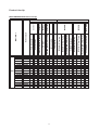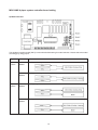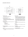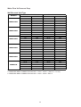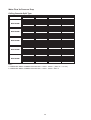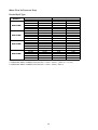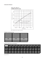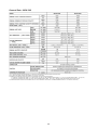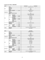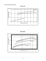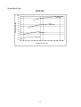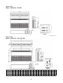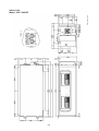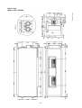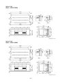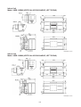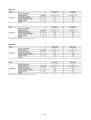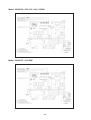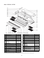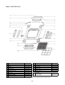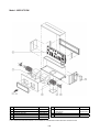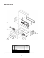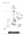
1
Catalog
Fan Coil Units
Models: MWM-GW
MCM-DW/EW
MCK-AW/BW/CW
MCC-CW
MDB-BW
MFCU - 2008
Table of Contents
Nomenclature ................................................................................................................. 1
Features ......................................................................................................................... 8
Application Information .................................................................................................. 10
Sound Data ................................................................................................................... 26
Selection Process ......................................................................................................... 29
Engineering and Physical Data ..................................................................................... 50
Performance Data ......................................................................................................... 90
Dimensional Data ......................................................................................................... 142
Electrical Data .............................................................................................................. 160
Wiring Diagrams ........................................................................................................... 165
Servicing and Maintenance .......................................................................................... 173
Troubleshooting ............................................................................................................ 174
Eploded View and Parts List ........................................................................................ 175
This manual supercedes MFCU-2007
Note : Installation and maintenance are to be performed only by qualified personnel who are
familiar with local codes and regulations, and experienced with this type of equipment.
Caution: Sharp edges and coil surfaces are a potential injury hazard. Avoid contact with them.
Warning : Moving machinery and electrical power hazard. May cause severe personal
injury or death. Disconnect and lock off power before servicing equipment.
"McQuay" is a registered trademark of McQuay International. All rights reserved.
c 2008 McQuay International. All rights reserved throughout the world.
Bulletin illustrations cover the general appearance of McQuay International products at the time of publication.
We reserve the right to change design and construction specifications at any time without notice.
Nomenc
la
tur
e
Nomencla
latur
ture
Production spec variation
Type of ref. connection
X : Not applicable
Electrical
A : 220 - 240V/1Ph/50Hz
F : 380 - 415V/3Ph/50Hz
U : 220 - 240V/1Ph/50Hz/60Hz
M
WM
025
G
W
-
A
X
AB
Piping
H : 4 pipes system
Model Type
W : Chilled water fan coil
Series
G : G series
Capacity
025 : 18,000 Btu/h (Cooling)
Model Name
WM : Wall mounted split type
CK : Ceiling cassette split type
CM : Ceiling exposed split type
CC : Ceiling concealed split type
DB : Ducted split type
Brand
M : McQuay
1
MWM
007GW
010GW
015GW
020GW
025GW
301W
Cool/Heat
x
x
x
x
x
x
x
x
x
x
x
x
x
x
x
x
x
x
x
x
x
x
x
x
x
x
x
x
x
x
x
x
x
x
x
x
x
x
x
x
x
Handset
Control
2
Left piping
Piping
Air Filter
x
x
x
x
x
x
x
x
x
x
x
Nano filter
x
x
x
x
x
x
x
x
x
x
x
Ionizer filter
Connection
x
1/2" BSP Female adaptor
x
Marking
x
CE mark
G7 Cooling Handset
G11 Cooling Handset
G11 Heat Pump Handset
Valve/Valveless
AXAA
AXAB
AXAA
AXAB
AXAA
AXAB
AXAA
AXAB
AXAA
AXAB
AXAB
PCB - W2_L
Nomenclature
Model Name
Product Line-Up
MWM-GW Product Line-Up
Classification
x
x
x
x
x
x
x
x
x
x
x
x
x
x
x
x
x
x
x
x
x
x
x
x
x
x
x
x
x
x
x
x
Product Line-Up
MCM-DW/CBW/EW Product Line-Up
020DW
025DW
030DW
040DW
MCM
050DW
007CBW
010CBW
015CBW
015EW
020EW
025EW
AXCC
AXCD
AXCE
AXCF
AXCG
AXCC
AXCD
AXCE
AXCF
AXCG
AXCC
AXCD
AXCE
AXCF
AXCG
AXCC
AXCD
AXCE
AXCF
AXCG
AXCC
AXCD
AXCE
AXCF
AXCG
UXBD
UXBE
UXBD
UXBE
UXBD
UXBE
AXAA
AXAB
AXAA
AXAB
AXAA
AXAB
x
x
x
x
x
x
x
x
x
x
x
x
x
x
x
x
x
x
x
x
x
x
x
x
x
x
x
x
x
x
x
x
x
x
x
x
x
x
x
x
x
x
x
x
x
x
x
x
x
x
x
x
x
x
x
x
x
x
x
x
x
x
x
x
x
x
x
x
x
x
x
x
x
x
x
x
x
x
x
x
x
x
x
x
x
x
x
x
x
x
x
x
x
x
x
x
x
x
x
x
x
x
x
x
x
x
x
x
x
x
x
x
x
x
x
x
x
x
x
x
x
x
x
x
x
x
x
x
x
x
x
x
x
x
x
x
x
3
x
x
x
x
x
x
x
x
x
x
x
x
x
x
x
x
x
x
x
x
x
x
x
x
x
x
x
x
x
x
x
x
x
x
x
x
x
3/4" BSP (female) brass union Connection
Marking
x
CE mark
NETWARE 3 (Cool/Heat)
SLM 3 (Heat pump)
G7 Heatpump Handset
G7 Cooling Handset
Cool/Heat
Valve/Valveless
W/out Control
W2.0 UCW
Nomenclature
Model Name
Control
Handset
Classification
x
x
x
x
x
x
x
x
x
x
x
x
x
x
x
x
x
x
x
x
x
x
x
x
x
x
x
x
x
x
x
x
x
x
x
x
x
Marking
Connection
CE mark
3/4" BSP (female) brass union
Auto air swing
PLCKAW-G7 Cooling
PLCKAW-G7 Heat Pump
PLCKAW-SLM 3 Heat Pump
PLCKAW-Netware 3
PLCKCW-G7 Cooling
PLCKCW-G7 Heat Pump
PLCKCW-SLM 3 Heat Pump
AXBE
x
x
x
x
x
x
x
x
x
x
025AW
AXBE
x
x
x
x
x
x
x
x
x
x
030AW
AXBE
x
x
x
x
x
x
x
x
x
x
040AW
AXBE
x
x
x
x
x
x
x
x
x
x
050AW
AXBE
x
x
x
x
x
x
x
x
x
x
010CW
AXAB
x
x
x
x
x
x
x
x
x
015CW
AXAB
x
x
x
x
x
x
x
x
x
020CW
AXAB
x
x
x
x
x
x
x
x
x
020AWH
AXAA
x
x
x
x
x
x
x
x
025AWH
AXAA
x
x
x
x
x
x
x
x
030AWH
AXAA
x
x
x
x
x
x
x
x
040AWH
AXAA
x
x
x
x
x
x
x
x
050AWH
AXAA
x
x
x
x
x
x
x
x
4
MCK-AWH
MCK-CW
Classification
PLCKAWH-G7 Heat Pump
4 Pipe System
MCK-AW
Handset
Handset (depend on panel)
Control
020AW
Nomenclature
Valve/Valveless
MCK
PCB - W2.0 UCW
Model Name
Product Line-Up
MCK-AW/AWH/CW Product Line-Up
Panel
Product Line-Up
MCC-CW Product Line-Up
010CW
AXBC
x
x
x
x
x
x
x
x
x
AXAK
x
x
x
x
x
AXBA
AXBC
x
x
x
x
x
x
x
x
x
x
x
x
AXAC
MCC
020CW
x
x
x
AXAK
x
x
x
x
x
AXBA
x
x
x
x
x
x
x
x
x
x
x
x
AXAC
025CW
x
x
x
AXAK
x
x
x
x
x
AXBA
AXBC
x
x
x
x
x
x
x
x
x
x
x
x
AXAA
028CW
x
x
x
AXAK
x
x
x
x
x
AXBA
x
x
x
x
x
x
x
x
x
x
x
x
x
x
x
x
x
x
x
x
x
x
x
x
x
x
x
x
x
x
x
x
x
x
x
x
x
x
x
x
AXAJ
AXBC
x
x
x
AXAJ
x
x
x
AXAJ
AXBC
x
x
AXAJ
Other
x
Filter
x
x
AXAC
015CW
Connection
Marking
x
x
AXBA
Piping
x
x
Left piping
x
x
Water Control
x
x
Valve Application only
AXAK
x
AXAC
Brass adaptor 7/8" BSP (Female)
x
Brass adaptor 3/4" BSP (Female)
x
CE mark
Cool/Heat
x
NETWARE 3 (COOL/HEAT)
Valve/Valveless
AXAJ
SLM 3 (Heat pump)
W2.0 UCW
Nomenclature
Model Name
Control
Handset
Classification
x
x
x
x
x
x
x
x
x
5
x
x
x
x
Product Line-Up
MCC-CW Product Line-Up
030CW
AXBC
x
x
x
x
x
x
x
x
x
AXAK
x
x
x
x
x
AXBA
AXBC
x
x
x
x
x
x
x
x
x
x
x
x
AXAA
MCC
040CW
x
x
x
AXAK
x
x
x
x
x
AXBA
x
x
x
x
x
x
x
x
x
x
x
x
AXAA
050CW
x
x
x
AXAK
x
x
x
x
x
AXBA
AXBC
x
x
x
x
x
x
x
x
AXAK
x
x
x
x
x
AXBA
AXBC
x
x
x
x
x
x
x
x
x
x
x
x
x
x
x
x
x
x
x
x
x
x
x
x
x
x
x
x
x
x
x
x
x
x
AXAJ
x
x
x
AXAA
060CW
x
x
x
AXAJ
x
x
x
AXAJ
AXBC
x
x
AXAJ
Other
x
Filter
x
x
AXAA
038CW
Connection
Marking
x
x
AXBA
Piping
x
x
Left piping
x
x
Water Control
x
x
Valve Application only
AXAK
x
AXAA
Brass adaptor 7/8" BSP (Female)
x
Brass adaptor 3/4" BSP (Female)
x
CE mark
Cool/Heat
x
NETWARE 3 (COOL/HEAT)
Valve/Valveless
AXAJ
SLM 3 (Heat pump)
W2.0 UCW
Nomenclature
Model Name
Control
Handset
Classification
x
x
x
x
x
x
x
x
x
x
x
x
x
x
x
x
6
x
x
x
x
x
x
x
Product Line-Up
MDB-BW Product Line-Up
7
Fea
tur
es
eatur
tures
Space Saving
Different types of fan coil units are designed to be both versatile and space saving to suit every interior design. Ceiling
concealed type for the sophisticated, luxurious floor space saving, all kind of interior decoration; ceiling exposed type for
economical and space saving installation; etc.
Zone Control
These fan coil units can be installed in different zones as each unit operates independently. Zone control on energy
saving, different comfort requirement; better air distribution needs can therefore be easily achieved.
Standardisation Of Fan Coil Unit Control
The fan coil unit controller is standardized using W2 I.C, which enables the selection of valve / valveless and cooling /
heating applications. This allows the user to choose the desired application by just plugging in or removing the jumpers
at certain connectors on the PCB. The advantages of these units are lesser inventory for finished goods stock and spare
parts. For more details, please refer to General Installation guide.
Unique Features For MWM Series
Easy Installation
The wall mounted fan coil unit is easily installed because of its compact size, slimness and light weight. Slim and short
outdoor unit can be easily installed even in a narrow balcony and passageway and yet have a stable profile.
Space Saving
No space is required on either floor or ceiling. This newly developed super slim design for wall mounting maximises floor
space usage and enhance ceiling appearance where ceilings are low.
Quiet Operation
Cooling comfort is improved by whisper-quiet operation which is achieved by a tangential fan.
Excellent Air Distribution
Air discharge direction can be adjusted in four directions, manually or automatically by using LCD remote control, coupled
with good air flow, the unit provides excellent air distribution.
Facilitated Maintenance Ensured
The new design cassette filter is slide-out type which can be easily removed at the air inlet grille for cleaning. Maintenance
is easy for electrical components, piping and wiring as these are all easily accessible by merely removing front plastic
panel.
Wireless Remote Control
The compact LCD transmitter is able to operate the air conditioner unit within the distance of 9 meters. Fan motor speed
can be set at low/medium/high or automatic. Sleep mode automatically increase set temperature since room temperature
is lower at night thus achieving comfort surrounding. Air flow direction can be controlled automatically. Room temperature
is controlled by electronic thermostat. The unit can be preset to on and off automatically for maximum of 15 hours by using
timer on/off.
Slit Fin
The unique Hydrophilic slit fin has greatly improved the air flow and the contact surfaces with the air thus to boost the
cooling capacity.
8
Unique Features For MCK Series
Built In High Head Drain Pump
The unit comes with a built in high head drain pump. Condensate water can be pumped up to 700mm and drain out
smoothly.
4-way Air Discharge And Air Swing
These features greatly improve the air distribution in the conditioned space.
Wireless And Wired Controller Option
Wireless Handset is the standard controller. However if wired controller required, Netware3 & SLM3 wired controller is a
wise choice(optional).
Unique Features For MCM-DW/EW Series
2-way Air Discharge And Air Swing
The 2-way air discharge couple with the air swing function, provide better air distribution in the conditioned space.
Easy Maintenance
The air filter and components can be easily accessed from the bottom of the unit. This make servicing and maintenance
become a simple task.
Wireless And Wired Controller Option
Wireless Handset is the standard controller. However if wired controller required, Netware3 & SLM3 wired controller is a
wise choice(optional).
Unique Features For MCC Series
Elegance And Prestige
As the unit is installed above the ceiling with only the supply and return air grille exposed to view, the air conditioned space
will appear as elegant and prestigious as a centralized air conditioned area.
Evergreen Design
This unit will never become obsolete as the unit is completely concealed away. Interior decoration for maximum aesthetic
beauty as well as interior design is easily achieved.
Superior Air Distribution
As the conditioned air can be distributed to every corner of the area by air duct, this will ensure more pleasant living
environment, thus provide extra comfort to the occupants.
Optional Duct Accessories
The optional duct accessories makes the ducting and installation work so easy.
Wired Controller
Netware3 & SLM3 wired controller offers simple and flexibility in controlling the unit.
Unique Features For MDB-BW Series
Superb Air Distribution
These units are designed with high air flow and static, enables adequate distribution of air to the desired space. Providing
comfort to every corner of the room.
Reliability
The structures are strong and robust to ensure the product operation life.
Versatile
Multiple rooms can be cooled together by just using one unit of MDB.
9
Applica
tion Inf
or
ma
tion
pplication
Infor
orma
mation
General Installation Guide
System Configuration
The standard controller board (W2) comes with a VALVE jumper and a HEAT jumper. The system can be
configured as the jumper selection listed below:
HEAT Jumper
VALVE Jumper
Heatpump Mode & Valve Application
¥
¥
Heatpump Mode & Valveless Application
¥
X
Cooling Mode & Valve Application
X
¥
Cooling Mode & Valveless Application
X
X
¥
Jumper Remained
X
Jumper Removed
CA
UTION !
CAUTION
Disconnect the power supply to the unit before attempting to connect the wiring
VALVE & HEAT Jumper Location
Model: MWM - GW / 301W
1. VALVE jumper is plugged into JVLV connector on the emergency switch board.
2. HEAT jumper is plugged into JMODE connector on the emergency switch board.
Model: MCK-AW/AWH/CW, MCM-DW/CBW/EW and MCC-CW
1. VALVE jumper is plugged into JVLV connector on the main board.
2. HEAT jumper is plugged into OD connector on the main board.
Model : MWM 007 / 010 / 015GW (IONIZER)
10
Model : MWM 020 / 025GW (IONIZER)
Model : MCM Series / MCC Series / MCK-AW/CW
11
MCK-AWH 4 pipes system controller board setting
A) Model selection
The standard controller board (W2.0) comes with a default setting for model selection. Please select the model
accordingly by using jumper.
System
2 Pipe
System
4 Pipe
System
Model
Function
M1 Model 1
Cooling or Heating
M2 Model 2
Cooling or Heating with Auxiliary Heater
M2 Model 2
Cooling Only with Boiler
M4 Model 4
Cooling or Heating with Boiler
12
B) Valve, Heat and Fan priority selection
Jumper
Fan Priority Jumper
With Jumper (Default)
User set speed or lower fan if auto
Without Jumper
Fan stop when thermostat cut off
Heat Jumper
Valve Jumper
mode is selected
For Heat pump
For Valve control (Model 1,2,3 & 4)
For cooling only
For valveless control (Model 1 & 2)
C) Others
The controller board comes with other option.
i) Unoccupied Mode
If the dry contact is closed, the Unoccupied mode is activated and vice versa. When Timer On is active, system
goes back to Occupied mode.
The dry contact connection points can be connected parallel with other fan coil unit (FCU) boards. If the dry
contact is closed, Unoccupied mode will be activated on all fan coil units that are connected parallel as shown in
figure below.
13
ii) Anti Freeze Mode
Anti Freeze operation has the highest priority among all unit operation. Anti Freeze operation will be activated
only if dry contact is closed and vice versa.
iii) Window Open Mode
The dry contact connection points can be connected in parallel with other fan coil unit (FCU) boards. If the dry
contact is closed, Window open mode will be activated on all the fan coil units which are connected in parallel as
shown in figure below.
iv) Load Shedding
The dry contact connection points can be connected in parallel with other fan coil unit (FCU) boards. If the dry
contact is closed, Load shedding mode will be activated on all the fan coil units which are connected in parallel
as shown in figure below.
Global Unoccupied, Global Window Open and Global Load Shedding operation could also be activated via the
network communication bus line by master controller with or without the above connection.
NOTE :
i) Auto Fan Mode is only applicable in Model 3 only. ( Cooling only with Boiler)
ii) Fan mode is not available in valveless control.
iii) Wired handset (Netware and SLM) has an indoor room sensor. Avoid locating the wired handset at isolated
places where room temperature reading will be inaccurate.
14
Water Piping Connection
The indoor unit is equipped with water outlet and inlet bare connection. There is an air-vent for air purging that is
fitted at the outlet water header.
3 ways solenoid valve is required for cycling off or bypass the chilled water.
Black steel pipe, polyethrene pipe, PVC pipe and copper tube recommended in field installation.
All types of piping and connection must be insulated by polyurethane (ARMAFLEX type or equivalent) to avoid
condensation.
Do not use contaminated or damaged pipe and fitting for installation.
Some main fitting components are needed in the system to enhance the capacity and ease of service, such as
gate valve, balancing valve, 2 ways or 3 ways solenoid valve, filter, strainer etc.
15
Preliminary Site Survey
Electrical supply and installation is to conform to LOCAL AUTHORITY's (e.g. National Electricity Board) CODES
and REGULATIONS.
Voltage supply fluctuation must not exceed ± 10% of rated voltage. Electricity supply lines must be independent
of welding transformers which can cause supply fluctuation.
Ensure that the location is convenient for wiring and piping.
Mounting
For ceiling mounted models, locate a position where piping and ducting work can be kept to a minimum.
Ensure that overhead supports are strong enough to hold the unit's weight. Position hanger rods and check for
alignment with the unit. Check that hangers are secure and that the base of fan coil unit is level in two horizontal
positions.
Piping
Drain and water piping must be accurately connected.
Please refer to "Specification Sheet" for piping sizes.
Piping Support
All water mains must be adequately supported to carry the necessary weight involved, provisions must be
made by the installing contractor to allow for adequate free movement of all vertical and horizontal risers and
run outs. Due to the fact that cold water will be circulated through the water mains, a sizeable movement of the
water mains can be expected due to contraction. If for example, the piping is rigidly supported with no provision
for movement, it is very possible that the tubing of fitting may be broken causing water leakage in the conditioned spaces throughout the building.
Coil Venting
Each standard basic unit coil is equipped with a manually operated air vent which is installed at the end of a
small copper line leading into the highest point of the coil. By means of this valve, air may be vented manually,
from the coil to keep it operating at full capacity. When water is first introduced into a coil, air is sometimes
trapped in the coil tubing. This trapped air will reduce cooling capacity and create "Bubbling" or "Clanking"
noise within the units. To release air trapped in the coil, press the air vent head to allow air to flow out of the air
vent opening. Release when a steady stream of water appear.
Electrical Connection
As wiring regulations differ from country to country, please refer to your LOCAL ELECTRICAL CODES for field
wiring regulations and ensure that they are complied with. Besides, take note of the following general precaution:
1) Ensure that the rated voltage of the unit corresponds to the name plate before commencing wiring work.
2) Provide a power outlet to be used exclusively for each unit and a power supply disconnect and a circuitbreaker for over-current protection should be provided in the exclusive line.
3) The unit must be EARTH to prevent possible hazards due to insulation failure.
4) All wiring must be firmly connected.
16
General Operation Guide
Start-Up
The following procedure must be completed before any attempts is made to put the entire system Into operation:
1) Piping connections completed.
2) Electrical connections completed.
3) Duct connections completed.
4) Auxiliary drain pans in position where required.
5) Drain line draining into drain pans.
6) Filters correctly installed and free of construction debris.
7) Motor-blower assembly rotates freely.
8) Unit Hydro-statically tested and air vented.
Starting The Fan Coil Unit
1) Turn on the switch of water pump.
2) Start water chiller.
3) Operate the fan coil unit by turning on the fan and set the control switch to get the desired speed.
4) Inspect the duct and piping condition and rectify problem (e.g. vibration, noise, etc.) if exist.
Servicing And Maintenance
Fan coil units are designed to operate continuously with minor routine maintenance. Since fan coil units cool
the discharging forced air, the efficiency with which the units operate is directly related to the amount of air
passing through the coil.
Air Filters
The function of the air filters is to remove foreign matter such as dirt, soot, pollen and certain other impurities
from the air passing through it. A clogged or dirty filter not only fails to do the job for which it is designed, but
restricts the flow of air over the coil.
The importance of cleaning the filter before it becomes clogged must be greatly stressed. The frequency with
which a filter should be cleaned will depend upon the amount of dust and foreign material that enters a unit, and
this depends upon location and situation.
The washable viledon or saranet filter may be cleaned by tapping the filter on a solid surface to dislodge heavy
particles. Wash under stream of warm water, with detergent if necessary. Dry it thoroughly before replacing.
Fan Motor
The fan motor is pre-lubricated and sealed at the factory. Therefore, no lubricating maintenance is required.
Coils
Clean coil unit by brushing between fins with a nylon brush. Brushing should be followed by cleaning with a
vacuum cleaner. The coil may also be cleaned by using a high pressure air hose and nozzle if a compressed air
source is available. It should be pointed out that if suitable air filter is used and taken care of properly, the coils
need no cleaning.
Drain Pipe
The drain pipe should be checked before operation of unit is begun. If it is clogged, steps should be taken to
clean the debris so that condensate will flow out easily.
Replacement Of Parts
Replacement of parts are available through your local dealers. When ordering parts, you must supply
1) Model name of the unit.
2) Serial number of the unit.
3) Part name and number.
17
Controller
Type Of Controller Vs Type Of Fan Coil
MODELS
STANDARD CONTROLLER
OPTIONAL CONTROLLER
MWM - GW
G11 (Wireless)
NETWARE3 / SLM3 (Wired)
MWM 301W
G7 (Wireless)
NETWARE3 / SLM3 (Wired)
MCK - AW / AWH / CW
G7 (Wireless)
NETWARE3 / SLM3 (Wired)
MCM - DW / CBW / EW
G7 (Wireless)
NETWARE3 / SLM3 (Wired)
MCC - CW
MDB - BW
NETWARE3 / SLM3 (Wired)
Without Controller
Self Diagnosis Table
Error Indication
Cool LED
7 Segment Display
Room Sensor error (short/open)
Blinks 1 times
E1
Pipe Water Sensor Error (short/open)
Blinks 2 times
E2
Water Pump Error
Blinks 6 times
E6
Pipe Water Temperature Fault
Blinks 5 times
E5
* Window Open Activated
Blinks 3 times
-
* Antifreeze Mode Activated
Blinks 7 times
-
* Load Shedding Activated
Blinks 8 times
-
* Only applicable for 4-pipe system
18
-
Operation Guide For G7
1
2
Transmission source
• The source where the signal will
be transmitted
Signal transmission
indication
• Blink to confirm the last setting
has been send to the unit.
4
Temperature setting
• To set the desired
•
•
3
room
temperature, press the button to
increase or decrease the set
temperature.
The temperature setting range
is from 16°C to 30°C (Optional
setting 18°C to 30°C).
Press
both
buttons
simultaneously to toggle the
temperature setting between °C
and °F.
On/Off button
• Press once to
•
5
Operation mode
• Press the MODE
•
6
Fan speed selection
• Press the button until
•
the
desired fan speed is achieved.
7
12
ON timer setting
• Press the SET button
•
•
9
8
will
activate the on timer function.
Set the desired on time by
pressing the SET button
continuously. If the timer is set
to 7.30am, the air conditioner
will turn on at 7.30 sharp.
Press the CLR button to cancel
the on timer setting.
•
Automatic air swing
• Press the SWING button
•
to
activate the automatic air swing
function.
To distribute the air to a specific
direction, press the SWING button and wait until the louver
move to the desired direction
and press the button once
again.
will
activate the off timer function.
Set the desired off time by
pressing the SET button
continuously.
Press the CLR button to cancel
the off timer setting.
Sleep mode setting
• Press the button to activate
•
•
11
button to
select the type of operating
mode.
For cooling only unit, the
available modes are : COOL,
DRY & FAN.
For heat pump unit, the
available modes are : AUTO,
COOL, DRY, FAN & HEAT.
OFF timer setting
• Press the SET button
•
10
start the air
conditioner.
Press again to stop the unit.
sleep mode. This function is
available under COOL, HEAT &
AUTO mode.
When it is activated in COOL
mode, the set temperature will
be increased 0.5°C after
30mins, 1°C after 1 hour and
2°C after 2 hours.
When it is activated in HEAT
mode, the set temperature will
be decreased 1°C after 30mins,
2°C after 1 hour and 3°C after 2
hours.
Clock time setting
• Press button + or - to increase
or decrease the clock time.
19
G11 Remote Controller
Temperature Setting
On/Off Button
x
x
Press Once to start the air
conditioner
x
Press again to stop the unit
To set the desired room
temperature, press the button to
increase or decrease the set
temperature.
x
The temperature setting range is
from 16qC to 30qC
x
Press both buttons simultaneously
to toggle the temperature setting
between qC and qF
Personalised Setting
x
Press and hold the button for 3s to
initiate personalized setting.
x
Set the individual setting e.g.
MODE, SET TEMP or FAN
SPEED and leave for 4s to save
x
2 groups of settings are allowed to
stored in the handset
Turbo Mode
x
Press the TURBO button to
achieve the required set
temperature in a short time.
Fan Speed Selection
Sleep Mode
x
x
x
x
Press the button to activate sleep
mode. This function is available
under COOL, HEAT & AUTO
mode.
Press the button until the desired
fan speed is achieved.
Operating Mode
When it is activated in COOL
mode, the set temperature will be
increased 0.5qC after 30mins, 1qC
after 1 hour and 2qC after 2 hours.
When it is activated in HEAT
mode, the set temperature will be
decreased 1qC after 30mins, 2qC
after 1 hour and 3qC after 2 hours.
ON Timer Setting
x
Press the MODE button to select
the type of operating mode.
x
For Cooling only unit, the available
modes are: COOL, DRY & FAN.
x
For Heatpump unit, the available
modes are: AUTO, COOL, DRY,
FAN & HEAT.
OFF Timer Setting
x
Press the SET button will activate
the on timer function.
x
Press the SET button will activate
the off timer function.
x
Set the desired on time by
pressing the SET button
continuously.
x
x
Press the CLR button to cancel the
off timer setting
Set the desired off time by
pressing the SET button
continuously.
x
Press the CLR button to cancel
the off timer setting
Clock Time Setting
x
Press button + or - to increase or
decrease the clock time.
Automatic Air Swing
x
Press the SWING button to
activate the automatic air swing
function.
x
To distribute the air to a specific
direction, press the SWING button
and wait until the louver move to
the desired direction and press the
button once again.
Ionizer
x
Press the button to activate the
negative Ion function, which will
refresh the indoor air effectively.
20
Netware3 Wired Controller
21
22
23
SLM3 WIRED CONTROLLER
SLM3
AC5300
1. "ON/OFF" switch
x Press to start the air conditioner unit.
x Press again to stop the unit.
2. Temperature setting
x Set the desired room temperature.
x Press button to increase or decrease the set temperature. Setting range are between 16°C to 30°C
(60°F to 80°F).
3. Operation Modes
x Press the "mode" button for select the type of operating mode.
- Cooling Only :
COOL, FAN, DRY
- Heat Pump :
COOL, FAN, DRY, HEAT
6. "Sleep" mode
x Press button to activate the sleep function. This
function can only be activated under "cool" or
heating mode operation. When it is activated
under "cool" mode operation, the set temperature will increase 0.5°C after 30 minutes, 1°C
after 1 hour and 2°C after 2 hours. If it is activated under "HEAT" mode operation, the set
temperature will be decreased 0.5° C after 30
minutes, 1° C after 1 hour and 2° C after 2 hours.
7. Air Swing
x Press button to activate the automatic air swing
function.
8. Sensor
x Infra red sensor to receive signals from wireless
controller.
4. Fan Speed selection
x Press the button until the desired fan speed is
achieved.
9. LED display
x To display the set temperature (in º C) and timer
delay setting (in hours).
5. Timer
x Press the set button to select the switch timer of the
air conditioner unit (the setting range is between 1
to 15 hours).
10. Transmission source
x To transmit signals to the air conditioner.
24
INSTALLATION OF LCD REMOTE CONTROLLER
STEP-BY-STEP GUIDE
i)
ii)
iii)
iv)
v)
First, open up the casing of the LCD remote controller into its top and bottom case using a screwdriver.
To do this, insert the screwdriver into the lower slot and slide it in the outward direction.
Fix the bottom case onto the wall with the 2 wooden screws provided. Then, insert the 4 connecting
wires (from the main board) through the slot on the lower center of the case as shown below.
Connect one end in each of the 3 wires to the terminal block behind the top case as illustrated.
To select cooling only model or heatpump model, some adjustment required in the dip switch setting.
Fasten back the top and bottom case into place. Hook the two upper claws into their respective slots and
snap the lower part shut.
Dip switch setting for model selection
Pin
Function
Remarks
JH & JD
RESERVE
JH-OFF, JD-OFF
COOL, DRY, FAN
JH-OFF, JD-ON
COOL, DRY, FAN, HEAT
JH-ON, JD-OFF
NO REAL TIME CLOCK
RTC-OFF
REAL TIME CLOCK
RTC-ON
WITHOUT DRY FUNCTION
NO DRY-ON
DRY FUNCTION
NO DRY-OFF
RTC
NO DRY
25
Sound Da
ta
Data
Sound Pressure Level
Wall Mounted Split Type
Model
MWM007GW
MWM010GW
MWM015GW
MWM020GW
MWM025GW
MWM301W
Speed
HIGH
MEDIUM
LOW
HIGH
MEDIUM
LOW
HIGH
MEDIUM
LOW
HIGH
MEDIUM
LOW
HIGH
MEDIUM
LOW
HIGH
MEDIUM
LOW
Microphone position :
1/1 Octave Sound Pressure Level (dB, ref 20PPa)
125 Hz
32
27
24
28
27
24
30
28
24
37
34
30
41
39
37
42
40
37
250 Hz
34
30
27
34
30
26
35
31
26
44
40
35
48
44
41
46
45
43
500 Hz
38
34
29
37
33
28
39
34
28
42
39
35
47
43
40
45
44
43
1k Hz
37
32
26
36
31
25
38
33
26
37
34
30
43
39
36
44
43
40
2k Hz
32
26
20
31
25
19
33
26
20
34
30
26
40
35
32
41
35
35
4k Hz
23
17
13
22
17
12
25
18
13
25
21
18
32
28
25
35
33
30
8k Hz
15
14
13
13
12
11
15
13
12
15
14
13
23
20
19
28
27
26
Overall
(dBA)
Noise
Criteria
40
35
29
39
34
28
42
36
29
43
40
35
49
44
42
49
47
45
36
31
24
35
30
23
37
32
24
37
34
30
43
38
35
43
42
39
MWM-FW -- 1 m in front of the unit and 0.8 m below the vertical centre line of the unit. (JIS C 9612)
MWM301W -- 1 m in front and 1 m below the air discharge opening of the unit (JIS B 8615)
Ceiling Exposed Split Type
Model
MCM020DW
MCM025DW
MCM030DW
MCM040DW
MCM050DW
Microphone position :
Model
MCM007CBW
MCM010CBW
MCM015CBW
Microphone position :
1/1 Octave Sound pressure level (dB, ref 20PPa)
Overall
125Hz
250Hz
500Hz
1kHz
2kHz
4kHz
8kHz
(dBA)
High
45
46
47
46
41
38
29
50
Medium
42
43
45
42
38
34
24
47
Low
36
37
39
35
31
24
15
40
High
48
51
51
50
45
41
33
54
Medium
47
50
50
49
44
40
32
53
Low
45
47
48
47
41
36
27
50
High
45
48
48
47
43
33
24
51
Medium
44
47
47
46
42
32
23
50
Low
43
45
45
44
39
29
20
48
High
51
53
51
50
47
37
30
54
Medium
48
51
50
49
46
36
28
53
Low
46
50
49
48
44
35
27
52
High
51
53
51
50
47
37
30
54
Medium
48
51
50
49
46
36
28
53
Low
46
50
49
48
44
35
27
52
MCM 20/25DW -- 1 m in front of the unit and 0.8 m below the air discharge opening. (JIS C 9612)
MCM 30/40/50DW -- 1 m in front of the unit and 1 m below the air discharge opening. (JIS B 8615)
Noise
Criteria
45
41
34
49
48
46
46
45
43
49
48
47
49
48
47
1/1 Octave Sound pressure level (dB, ref 20PPa)
125Hz
250Hz
500Hz
1kHz
2kHz
4kHz
High
26
34
38
42
38
35
Medium
23
29
36
39
34
31
Low
19
26
33
34
31
23
High
27
35
39
43
39
36
Medium
24
30
37
40
35
32
Low
20
27
34
35
32
24
High
28
36
40
44
40
37
Medium
25
31
38
41
36
33
Low
21
28
35
36
33
25
1m in front and 0.8m below the vertical centre line of the unit.
Noise
Criteria
41
38
33
42
39
34
43
40
35
Speed
Speed
26
8kHz
23
18
12
24
19
13
25
20
13
Overall
A (dBA)
45
42
37
46
43
38
47
44
39
Ceiling Cassette Split Type
Model
MCK020AW / AWH
MCK025AW / AWH
MCK030AW / AWH
MCK040AW / AWH
MCK050AW / AWH
Microphone position :
Model
MCK010CW
MCK015CW
MCK020CW
Microphone position :
Speed
High
Medium
Low
High
Medium
Low
High
Medium
Low
High
Medium
Low
High
Medium
Low
125Hz
46
44
43
48
45
43
50
48
46
50
48
46
54
52
51
1/1 Octave Sound pressure level (dB, ref 20PPa)
250Hz
500Hz
1kHz
2kHz
4kHz
45
40
38
32
21
43
37
33
28
18
42
35
31
26
17
46
43
39
33
27
43
40
35
29
21
42
38
32
27
19
48
47
43
37
35
45
43
38
32
31
43
41
35
30
30
49
49
46
39
38
47
47
43
36
34
45
46
41
34
30
52
51
48
43
42
50
50
46
41
40
49
49
45
39
39
8kHz
14
12
11
19
15
14
28
27
26
31
25
23
34
32
31
Overall
(dBA)
42
39
37
45
42
40
49
45
43
51
48
46
53
52
50
Noise
Criteria
37
32
31
38
35
33
42
38
36
45
42
41
47
46
45
8kHz
20
19
17
19
17
16
26
23
20
Overall
(dBA)
44
43
42
44
42
41
47
46
44
Noise
Criteria
39
38
36
38
37
35
41
40
38
MCK020/025AW/AWH -- 1.4m below the facia. (JIS C 9612)
MCK030/040/050AW/AWH -- 1.5 m below the facia. (JIS B 8615)
Speed
High
Medium
Low
High
Medium
Low
High
Medium
Low
125Hz
43
42
41
45
44
43
46
45
43
1/1 Octave Sound pressure level (dB, ref 20PPa)
250Hz
500Hz
1kHz
2kHz
4kHz
46
43
40
33
30
44
42
39
32
28
43
40
37
30
25
43
42
39
34
30
42
40
38
33
28
41
39
36
31
25
46
45
42
36
38
46
43
41
35
37
44
42
39
33
35
1.4m below the facia. (JIS C 9612)
27
Ceiling Concealed Fan Coil Unit
Model
MCC010CW
MCC015CW
MCC020CW
MCC025CW
MCC028CW
MCC030CW
MCC038CW
MCC040CW
MCC050CW
MCC060CW
Ext. Static
(mmAq)
5
4
3
5
4
3
5
4
3
5
4
3
10
8
7
6
21
17
13
9
14
12
11
9
21
18
13
9
18
16
14
11
18
16
14
10
Microphone position :
Speed
High
Medium
Low
High
Medium
Low
High
Medium
Low
High
Medium
Low
Super High
High
Medium
Low
Super High
High
Medium
Low
Super High
High
Medium
Low
Super High
High
Medium
Low
Super High
High
Medium
Low
Super High
High
Medium
Low
125Hz
33
31
28
39
35
32
42
41
40
42
41
36
48
45
42
36
54
50
45
42
56
54
51
47
56
54
49
45
56
54
53
51
57
55
53
51
1/1 Octave Sound pressure level (dB, ref 20PPa)
250Hz
500Hz
1kHz
2kHz
4kHz
30
30
29
22
16
28
28
26
20
13
25
24
22
16
10
36
34
32
27
18
34
32
29
23
14
29
28
25
17
11
39
36
34
28
22
37
34
31
26
20
36
32
29
23
18
41
37
34
31
29
40
36
33
29
28
35
33
31
26
27
45
42
38
34
29
42
39
35
31
26
38
37
32
28
22
33
33
27
23
16
50
46
45
40
34
45
43
42
37
31
40
40
38
32
26
36
37
33
28
22
57
53
50
46
41
51
48
46
41
36
48
46
45
37
32
45
44
41
34
28
49
49
46
41
37
47
47
45
39
35
42
43
41
35
31
39
41
37
30
26
50
50
49
44
38
49
49
48
43
37
47
46
47
40
35
45
44
44
36
32
50
51
51
46
39
49
49
50
44
37
46
47
47
39
34
43
44
43
35
30
Overall
(dBA)
33
30
26
37
34
29
38
36
34
40
39
36
44
41
38
34
49
46
42
38
55
51
48
45
51
49
45
41
53
52
50
47
55
53
50
47
8kHz
10
8
7
11
9
8
17
15
13
23
22
21
26
22
17
11
30
26
20
15
36
31
26
22
32
29
24
18
33
32
29
26
35
33
28
24
Noise
Criteria
27
24
20
31
27
23
33
30
27
33
32
30
37
34
32
27
44
41
37
32
49
45
44
40
45
44
40
36
48
47
46
43
50
49
46
42
1.4 m below the centre of the unit. (GB standard - GB/D17758 )
Tested with 2m length duct at the air discharge outlet and air return inlet.
Ducted Split Fan Coil Unit
Model
MDB075BW
MDB100BW
MDB125BW
MDB150BW
Microphone Position:
125 Hz
54
53
53
58
1/1 Octave Sound Pressure Level (dB, ref 20PPa)
250 Hz
500 Hz
1k Hz
2k Hz
4k Hz
50
46
44
41
36
54
48
48
44
39
51
50
45
44
38
56
57
54
52
47
8k Hz
26
31
29
39
Overall
(dBA)
Noise
Criteria
49
52
52
59
43
47
46
54
MDB075/100/125/150BW, 1.4m below the unit (free return and the discharge air was ducted to adjacent room )
28
Selection Pr
ocess
Process
Fan Performance Curves
FAN PERFORMANCE CURVE
MCC 010CW
29
FAN PERFORMANCE CURVE
MCC 015CW
30
FAN PERFORMANCE CURVE
MCC 020CW
31
FAN PERFORMANCE CURVE
MCC 025CW
32
FAN PERFORMANCE CURVE
MCC 028CW
33
FAN PERFORMANCE CURVE
MCC 030CW
34
FAN PERFORMANCE CURVE
MCC 038CW
35
FAN PERFORMANCE CURVE
MCC 040CW
36
FAN PERFORMANCE CURVE
MCC 050CW
37
FAN PERFORMANCE CURVE
MCC 060CW
38
FAN PERFORMANCE CURVE
MDB 075BW
39
FAN PERFORMANCE CURVE
MDB 100BW
40
FAN PERFORMANCE CURVE
MDB 125BW
41
FAN PERFORMANCE CURVE
MDB 150BW
42
Water Flow Vs Pressure Drop
Wall Mounted Split Type
MODELS
MWM007GW
MWM010GW
MWM015GW
MWM020GW
MWM025GW
MWM301W
FLOW RATE
LITRES/M
USGPM
4.20
1.11
5.60
1.48
7.00
1.85
8.40
2.22
9.80
2.59
4.79
1.27
6.39
1.69
7.99
2.11
9.58
2.53
11.18
2.95
5.40
1.43
7.21
1.90
9.01
2.38
10.81
2.86
12.61
3.33
7.99
2.11
10.66
2.82
13.32
3.52
15.99
4.22
18.65
4.93
8.28
2.19
11.04
2.92
13.80
3.65
16.56
4.38
19.32
5.10
10.45
2.76
13.93
3.68
17.41
4.60
20.89
5.52
24.38
6.44
WATER PRESSURE DROP
kPa
PSI
15.99
2.32
26.43
3.84
39.28
5.70
54.38
7.89
71.84
10.43
18.97
2.75
31.45
4.56
46.87
6.80
65.11
9.45
85.91
12.47
24.42
3.54
40.48
5.88
60.65
8.80
84.15
12.21
111.22
16.14
13.19
1.91
22.14
3.21
33.07
4.80
46.01
6.68
61.35
8.90
14.02
2.03
23.50
3.41
35.14
5.10
48.90
7.10
65.22
9.47
16.26
2.36
27.28
3.96
40.86
5.93
57.39
8.33
76.34
11.08
Note :
a. PRESSURE DROP CORRECTION FACTOR = 1.2947 - 0.0021 * ( EWT°C * 1.8 + 32 )
b. PRESSURE DROP CORRECTION FACTOR = 1.2947 - 0.0021 * EWT°F
43
Water Flow Vs Pressure Drop
Ceiling Exposed Split Type
MODELS
MCM020DW
MCM025DW
MCM030DW
MCM040DW
MCM050DW
MCM007CBW
MCM010CBW
MCM015CBW
FLOW RATE
LITRES/M
USGPM
8.86
2.34
11.81
3.12
14.76
3.90
17.71
4.68
20.67
5.46
9.54
2.52
12.72
3.36
15.90
4.20
19.08
5.04
22.26
5.88
11.13
2.94
14.84
3.92
18.55
4.90
22.26
5.88
25.97
6.86
19.53
5.16
26.04
6.88
32.55
8.60
39.06
10.32
45.57
12.04
21.12
5.58
28.16
7.44
35.20
9.30
42.24
11.16
49.28
13.02
2.95
0.78
3.94
1.04
4.92
1.30
5.90
1.56
6.89
1.82
4.09
1.08
5.45
1.44
6.81
1.80
8.18
2.16
9.54
2.52
5.22
1.38
6.96
1.84
8.71
2.30
10.45
2.76
12.19
3.22
WATER PRESSURE DROP
kPa
PSI
5.17
0.750
8.68
1.260
13.02
1.890
18.12
2.630
24.18
3.510
5.93
0.860
9.92
1.440
14.88
2.160
20.74
3.010
27.70
4.020
5.24
0.760
8.75
1.270
13.09
1.900
18.26
2.650
24.39
3.540
3.65
0.530
6.06
0.880
9.09
1.320
12.61
1.830
16.74
2.430
4.20
0.610
7.03
1.020
10.47
1.520
14.54
2.110
19.43
2.820
2.66
0.386
4.40
0.639
6.58
0.955
9.13
1.325
12.06
1.750
4.73
0.686
7.93
1.151
11.84
1.719
16.49
2.393
21.85
3.171
1.38
0.200
2.27
0.330
3.38
0.490
4.70
0.682
6.20
0.900
Note :
a. PRESSURE DROP CORRECTION FACTOR = 1.2947 - 0.0021 * ( EWT°C * 1.8 + 32 )
b. PRESSURE DROP CORRECTION FACTOR = 1.2947 - 0.0021 * EWT°F
44
Water Flow Vs Pressure Drop
Ceiling Cassette Split Type
MODELS
MCK020AW
MCK025AW
MCK030AW
MCK040AW
MCK050AW
FLOW RATE
LITRES/M
USGPM
12.49
3.30
16.65
4.40
20.82
5.50
24.98
6.60
29.14
7.70
13.17
3.48
17.56
4.64
21.95
5.80
26.34
6.96
30.73
8.12
15.22
4.02
20.29
5.36
25.36
6.70
30.43
8.04
35.50
9.38
16.58
4.38
22.10
5.84
27.63
7.30
33.16
8.76
38.68
10.22
17.03
4.50
22.71
6.00
28.39
7.50
34.07
9.00
39.74
10.50
WATER PRESSURE DROP
kPa
PSI
6.68
0.970
11.16
1.620
16.74
2.430
23.56
3.420
31.28
4.540
7.34
1.066
12.33
1.790
18.47
2.680
25.98
3.770
34.52
5.010
9.51
1.380
16.05
2.330
24.25
3.520
33.90
4.920
45.20
6.560
11.16
1.620
18.74
2.720
28.39
4.120
39.76
5.770
53.05
7.700
11.71
1.700
19.71
2.860
29.83
4.330
41.82
6.070
55.81
8.100
Note :
a. PRESSURE DROP CORRECTION FACTOR = 1.2947 - 0.0021 * ( EWT°C * 1.8 + 32 )
b. PRESSURE DROP CORRECTION FACTOR = 1.2947 - 0.0021 * EWT°F
45
Water Flow Vs Pressure Drop
Ceiling Cassette Split Type
MODELS
MCK010CW
MCK015CW
MCK020CW
MCK020AWH
MCK025AWH
MCK030AWH
MCK040AWH
MCK050AWH
FLOW RATE
LITRES/M
USGPM
4.31
1.14
5.75
1.52
7.19
1.90
8.63
2.28
10.07
2.66
7.61
2.01
10.14
2.68
12.68
3.35
15.22
4.02
17.75
4.69
8.18
2.16
10.90
2.88
13.63
3.60
16.35
4.32
19.08
5.04
9.08
2.40
12.11
3.20
15.14
4.00
18.17
4.80
21.20
5.60
9.77
2.58
13.02
3.44
16.28
4.30
19.53
5.16
22.79
6.02
11.36
3.00
15.14
4.00
18.93
5.00
22.71
6.00
26.50
7.00
12.49
3.30
16.65
4.40
20.82
5.50
24.98
6.60
29.14
7.70
12.72
3.36
16.96
4.48
21.20
5.60
25.44
6.72
29.67
7.84
WATER PRESSURE DROP
kPa
PSI
17.69
2.567
29.70
4.311
44.37
6.440
61.80
8.970
82.47
11.969
9.68
1.404
16.05
2.330
24.00
3.483
33.29
4.831
43.99
6.384
10.99
1.595
18.23
2.646
27.30
3.962
37.93
5.506
50.14
7.277
1.92
0.278
3.20
0.465
4.78
0.694
6.64
0.964
8.80
1.277
2.18
0.316
3.64
0.529
5.44
0.790
7.58
1.100
10.04
1.457
2.85
0.413
4.79
0.695
7.17
1.040
9.98
1.449
13.34
1.936
3.40
0.493
5.68
0.825
8.52
1.237
11.97
1.738
15.92
2.310
3.51
0.509
5.88
0.853
8.81
1.279
12.38
1.797
16.45
2.388
Note :
a. PRESSURE DROP CORRECTION FACTOR = 1.2947 - 0.0021 * ( EWT°C * 1.8 + 32 )
b. PRESSURE DROP CORRECTION FACTOR = 1.2947 - 0.0021 * EWT°F
46
Water Flow Vs Pressure Drop
Ceiling Concealed Split Type
MODELS
MCC010CW
MCC015CW
MCC020CW
MCC025CW
MCC028CW
MCC030CW
MCC038CW
MCC040CW
MCC050CW
MCC060CW
FLOW RATE
LITRES/M
USGPM
4.54
1.20
6.06
1.60
7.57
2.00
9.08
2.40
10.60
2.80
5.86
1.55
7.81
2.06
9.77
2.58
11.72
3.10
13.67
3.61
9.54
2.52
12.72
3.36
15.90
4.20
19.08
5.04
22.26
5.88
10.67
2.82
14.23
3.76
17.79
4.70
21.35
5.64
24.91
6.58
12.94
3.42
17.26
4.56
21.57
5.70
25.89
6.84
30.20
7.98
14.08
3.72
18.77
4.96
23.47
6.20
28.16
7.44
32.85
8.68
21.80
5.76
29.07
7.68
36.34
9.60
43.60
11.52
50.87
13.44
16.81
4.44
22.41
5.92
28.01
7.40
33.61
8.88
39.21
10.36
22.71
6.00
30.28
8.00
37.85
10.00
45.42
12.00
52.99
14.00
24.53
6.48
32.70
8.64
40.88
10.80
49.05
12.96
57.23
15.12
WATER PRESSURE DROP
kPa
PSI
2.69
0.390
4.48
0.650
6.68
0.970
9.30
1.350
12.26
1.780
4.27
0.620
7.17
1.040
10.75
1.560
14.95
2.170
19.77
2.870
5.65
0.820
9.51
1.380
14.19
2.060
19.77
2.870
26.46
3.840
7.51
1.090
12.61
1.830
18.95
2.750
26.60
3.860
35.41
5.140
4.55
0.660
7.58
1.100
11.37
1.650
15.78
2.290
21.08
3.060
3.93
0.570
6.61
0.960
9.85
1.430
13.71
1.990
18.19
2.640
13.99
2.030
23.56
3.420
35.76
5.190
51.33
7.450
54.57
7.920
3.65
0.530
9.85
1.430
14.68
2.130
20.53
2.980
27.42
3.980
11.64
1.690
19.57
2.840
29.63
4.300
41.55
6.030
55.40
8.040
2.14
0.310
3.51
0.510
5.37
0.780
7.44
1.080
9.85
1.430
Note :
a. PRESSURE DROP CORRECTION FACTOR = 1.2947 - 0.0021 * ( EWT°C * 1.8 + 32 )
b. PRESSURE DROP CORRECTION FACTOR = 1.2947 - 0.0021 * EWT°F
47
Water Flow Vs Pressure Drop
Ducted Split Type
MODELS
MDB075BW
MDB100BW
MDB125BW
MDB150BW
FLOW RATE
LITRES/M
USGPM
37.02
9.78
49.36
13.04
61.70
16.30
74.03
19.56
86.37
22.82
45.42
12.00
60.56
16.00
75.70
20.00
90.84
24.00
105.98
28.00
61.54
16.26
82.06
21.68
102.57
27.10
123.09
32.52
143.60
37.94
79.49
21.00
105.98
28.00
132.48
35.00
158.97
42.00
185.47
49.00
WATER PRESSURE DROP
kPa
PSI
6.29
0.913
10.54
1.530
15.85
2.300
22.32
3.240
29.70
4.310
5.06
0.735
8.47
1.230
12.68
1.840
17.85
2.590
23.70
3.440
7.10
1.030
11.92
1.730
17.91
2.600
25.22
3.660
33.55
4.870
5.93
0.860
9.65
1.400
14.88
2.160
20.88
3.030
27.84
4.040
Note :
a. PRESSURE DROP CORRECTION FACTOR = 1.2947 - 0.0021 * ( EWT°C * 1.8 + 32 )
b. PRESSURE DROP CORRECTION FACTOR = 1.2947 - 0.0021 * EWT°F
48
Correction Factors
Altitude Correction Factors
Elevation, m
0
300
600
900
1200
1500
1800
Total Capacity
1.00
0.99
0.98
0.97
0.96
0.94
0.93
Sensible Capacity
1.00
0.96
0.93
0.90
0.86
0.83
0.80
Heating Capacity Correction Factors
EAT
°C
4.4
7.2
10.0
12.7
15.5
18.3
21.1
23.9
26.7
37.8
0.838
0.771
0.700
0.631
0.562
0.493
0.424
0.354
0.284
43.3
0.980
0.913
0.843
0.773
0.705
0.636
0.567
0.498
0.428
45
1.021
0.954
0.885
0.817
0.748
0.679
0.610
0.541
0.471
48.8
1.122
1.055
0.986
0.918
0.848
0.779
0.711
0.642
0.573
ENTERING TEMPERATURE, °C
54.4
60
65.5
1.265
1.406
1.552
1.198
1.379
1.485
1.130
1.272
1.417
1.062
1.205
1.349
0.992
1.137
1.281
0.923
1.070
1.212
0.855
1.000
1.146
0.786
0.932
1.078
0.717
0.863
1.008
71.1
1.698
1.631
1.563
1.495
1.427
1.358
1.290
1.222
1.155
76.7
1.845
1.778
1.710
1.639
1.572
1.504
1.438
1.369
1.302
82.2
1.988
1.920
1.853
1.786
1.719
1.650
1.583
1.515
1.449
87.7
2.134
2.067
2.000
1.931
1.865
1.799
1.730
1.664
1.597
Notes : Adjusted capacity, W (@ Nominal air flow) = base heating capacity (@ nominal 60°C EWT, 21.1°C EAT) x Heating Capacity
Correction Factor
49
Engineering and Ph
ysical Da
ta
Physical
Data
General Data - MWM-GW
1) ALL SPECIFICATIONS ARE SUBJECTED TO CHANGE BY THE MANUFACTURER WITHOUT PRIOR NOTICE.
2) ALL UNITS ARE BEING TESTED AND COMPLY TO ISO 5151 & ISO13253.
3) NOMINAL COOLING AND HEATING CAPACITY ARE BASED ON THE CONDITIONS BELOW :
a) COOLING - ENTERING AIR TEMP. : 27°C (80.6°F) DB / 19°C (66.2°F) WB, ENTERING WATER TEMP. : 7°C (44.6°F), LEAVING WATER TEMP. : 12°C (53.6°F)
b) HEATING - ENTERING AIR TEMP.: 20°C (68°F) DB, ENTERING WATER TEMP. : 50°C (122°F), WATER FLOW RATE BASED ON COOLING CYCLE.
4) SOUND PRESSURE LEVEL ARE ACCORDING TO JIS C 9612 STANDARD. POSITION OF THE MEASUREMENT POINT IS 1m IN FRONT AND
0.8m BELOW THE VERTICAL CENTRE LINE OF THE UNIT.
50
General Data - MWM-GW
1) ALL SPECIFICATIONS ARE SUBJECTED TO CHANGE BY THE MANUFACTURER WITHOUT PRIOR NOTICE.
2) ALL UNITS ARE BEING TESTED AND COMPLY TO ISO 5151 & ISO13253.
3) NOMINAL COOLING AND HEATING CAPACITY ARE BASED ON THE CONDITIONS BELOW :
a) COOLING - ENTERING AIR TEMP. : 27°C (80.6°F) DB / 19°C (66.2°F) WB, ENTERING WATER TEMP. : 7°C (44.6°F), LEAVING WATER TEMP. : 12°C (53.6°F)
b) HEATING - ENTERING AIR TEMP.: 20°C (68°F) DB, ENTERING WATER TEMP. : 50°C (122°F), WATER FLOW RATE BASED ON COOLING CYCLE.
4) SOUND PRESSURE LEVEL ARE ACCORDING TO JIS C 9612 STANDARD. POSITION OF THE MEASUREMENT POINT IS 1m IN FRONT AND
0.8m BELOW THE VERTICAL CENTRE LINE OF THE UNIT.
51
General Data - MWM301W
1) ALL SPECIFICATIONS ARE SUBJECTED TO CHANGE BY THE MANUFACTURER WITHOUT PRIOR NOTICE.
2) ALL UNITS ARE BEING TESTED AND COMPLY TO ISO 5151 & ISO13253.
3) NOMINAL COOLING AND HEATING CAPACITY ARE BASED ON THE CONDITIONS BELOW :
a) COOLING - ENTERING AIR TEMP. : 27°C (80.6°F) DB / 19°C (66.2°F) WB, ENTERING WATER TEMP. : 7°C (44.6°F), LEAVING WATER TEMP. : 12°C (53.6°F)
b) HEATING - ENTERING AIR TEMP.: 20°C (68°F) DB, ENTERING WATER TEMP. : 50°C (122°F), WATER FLOW RATE BASED ON COOLING CYCLE.
4) SOUND PRESSURE LEVEL ARE ACCORDING TO JIS C 9612 STANDARD. POSITION OF THE MEASUREMENT POINT IS 1m IN FRONT AND
0.8m BELOW THE VERTICAL CENTRE LINE OF THE UNIT.
52
General Data - MCK-AW
1) ALL SPECIFICATIONS ARE SUBJECTED TO CHANGE BY THE MANUFACTURER WITHOUT PRIOR NOTICE.
2) ALL UNITS ARE BEING TESTED AND COMPLY TO ISO 5151 & ISO13253.
3) NOMINAL COOLING AND HEATING CAPACITY ARE BASED ON THE CONDITIONS BELOW :
a) COOLING - ENTERING AIR TEMP. : 27°C (80.6°F) DB / 19°C (66.2°F) WB, ENTERING WATER TEMP. : 7°C (44.6°F), LEAVING WATER TEMP. : 12°C (53.6°F)
b) HEATING - ENTERING AIR TEMP.: 20°C (68°F) DB, ENTERING WATER TEMP. : 50°C (122°F), WATER FLOW RATE BASED ON COOLING CYCLE.
4) SOUND PRESSURE LEVEL ARE ACCORDING TO JIS C 9612 STANDARD. MCK020/025AW : POSITION OF THE MEASUREMENT POINT IS 1.4m
BELOW THE FACIA. MCK030/040/050AW : 1.5m BELOW THE FACIA (JIS B 8615).
53
General Data - MCK-AW
1) ALL SPECIFICATIONS ARE SUBJECTED TO CHANGE BY THE MANUFACTURER WITHOUT PRIOR NOTICE.
2) ALL UNITS ARE BEING TESTED AND COMPLY TO ISO 5151 & ISO13253.
3) NOMINAL COOLING AND HEATING CAPACITY ARE BASED ON THE CONDITIONS BELOW :
a) COOLING - ENTERING AIR TEMP. : 27°C (80.6°F) DB / 19°C (66.2°F) WB, ENTERING WATER TEMP. : 7°C (44.6°F), LEAVING WATER TEMP. : 12°C (53.6°F)
b) HEATING - ENTERING AIR TEMP.: 20°C (68°F) DB, ENTERING WATER TEMP. : 50°C (122°F), WATER FLOW RATE BASED ON COOLING CYCLE.
4) SOUND PRESSURE LEVEL ARE ACCORDING TO JIS C 9612 STANDARD. MCK020/025AW : POSITION OF THE MEASUREMENT POINT IS 1.4m
BELOW THE FACIA. MCK030/040/050AW : 1.5m BELOW THE FACIA (JIS B 8615).
54
General Data - MCK-AW
1) ALL SPECIFICATIONS ARE SUBJECTED TO CHANGE BY THE MANUFACTURER WITHOUT PRIOR NOTICE.
2) ALL UNITS ARE BEING TESTED AND COMPLY TO ISO 5151 & ISO13253.
3) NOMINAL COOLING AND HEATING CAPACITY ARE BASED ON THE CONDITIONS BELOW :
a) COOLING - ENTERING AIR TEMP. : 27°C (80.6°F) DB / 19°C (66.2°F) WB, ENTERING WATER TEMP. : 7°C (44.6°F), LEAVING WATER TEMP. : 12°C (53.6°F)
b) HEATING - ENTERING AIR TEMP.: 20°C (68°F) DB, ENTERING WATER TEMP. : 50°C (122°F), WATER FLOW RATE BASED ON COOLING CYCLE.
4) SOUND PRESSURE LEVEL ARE ACCORDING TO JIS C 9612 STANDARD. MCK020/025AW : POSITION OF THE MEASUREMENT POINT IS 1.4m
BELOW THE FACIA. MCK030/040/050AW : 1.5m BELOW THE FACIA (JIS B 8615).
55
General Data - MCK-AWH
1) ALL SPECIFICATIONS ARE SUBJECTED TO CHANGE BY THE MANUFACTURER WITHOUT PRIOR NOTICE.
2) ALL UNITS ARE BEING TESTED AND COMPLY TO ISO 5151 & ISO13253.
3) NOMINAL COOLING AND HEATING CAPACITY ARE BASED ON THE CONDITIONS BELOW :
a) COOLING - ENTERING AIR TEMP. : 27°C (80.6°F) DB / 19°C (66.2°F) WB, ENTERING WATER TEMP. : 7°C (44.6°F), LEAVING WATER TEMP. : 12°C (53.6°F)
b) HEATING - ENTERING AIR TEMP.: 20°C (68°F) DB, ENTERING WATER TEMP. : 70°C (158°F), WATER FLOW RATE BASED ON COOLING CYCLE.
4) SOUND PRESSURE LEVEL ARE ACCORDING TO JIS C 9612 STANDARD. MCK020/025AWH : POSITION OF THE MEASUREMENT POINT IS 1.4m
BELOW THE FACIA. MCK030/040/050AWH : 1.5m BELOW THE FACIA (JIS B 8615).
56
General Data - MCK-AWH
1) ALL SPECIFICATIONS ARE SUBJECTED TO CHANGE BY THE MANUFACTURER WITHOUT PRIOR NOTICE.
2) ALL UNITS ARE BEING TESTED AND COMPLY TO ISO 5151 & ISO13253.
3) NOMINAL COOLING AND HEATING CAPACITY ARE BASED ON THE CONDITIONS BELOW :
a) COOLING - ENTERING AIR TEMP. : 27°C (80.6°F) DB / 19°C (66.2°F) WB, ENTERING WATER TEMP. : 7°C (44.6°F), LEAVING WATER TEMP. : 12°C (53.6°F)
b) HEATING - ENTERING AIR TEMP.: 20°C (68°F) DB, ENTERING WATER TEMP. : 70°C (158°F), WATER FLOW RATE BASED ON COOLING CYCLE.
4) SOUND PRESSURE LEVEL ARE ACCORDING TO JIS C 9612 STANDARD. MCK020/025AWH : POSITION OF THE MEASUREMENT POINT IS 1.4m
BELOW THE FACIA. MCK030/040/050AWH : 1.5m BELOW THE FACIA (JIS B 8615).
57
General Data - MCK-AWH
1) ALL SPECIFICATIONS ARE SUBJECTED TO CHANGE BY THE MANUFACTURER WITHOUT PRIOR NOTICE.
2) ALL UNITS ARE BEING TESTED AND COMPLY TO ISO 5151 & ISO13253.
3) NOMINAL COOLING AND HEATING CAPACITY ARE BASED ON THE CONDITIONS BELOW :
a) COOLING - ENTERING AIR TEMP. : 27°C (80.6°F) DB / 19°C (66.2°F) WB, ENTERING WATER TEMP. : 7°C (44.6°F), LEAVING WATER TEMP. : 12°C (53.6°F)
b) HEATING - ENTERING AIR TEMP.: 20°C (68°F) DB, ENTERING WATER TEMP. : 70°C (158°F), WATER FLOW RATE BASED ON COOLING CYCLE.
4) SOUND PRESSURE LEVEL ARE ACCORDING TO JIS C 9612 STANDARD. MCK020/025AWH : POSITION OF THE MEASUREMENT POINT IS 1.4m
BELOW THE FACIA. MCK030/040/050AWH : 1.5m BELOW THE FACIA (JIS B 8615).
58
General Data - MCK-CW
1) ALL SPECIFICATIONS ARE SUBJECTED TO CHANGE BY THE MANUFACTURER WITHOUT PRIOR NOTICE.
2) ALL UNITS ARE BEING TESTED AND COMPLY TO ISO 5151 & ISO13253.
3) NOMINAL COOLING AND HEATING CAPACITY ARE BASED ON THE CONDITIONS BELOW :
a) COOLING - ENTERING AIR TEMP. : 27°C (80.6°F) DB / 19°C (66.2°F) WB, ENTERING WATER TEMP. : 7°C (44.6°F), LEAVING WATER TEMP. : 12°C (53.6°F)
b) HEATING - ENTERING AIR TEMP.: 20°C (68°F) DB, ENTERING WATER TEMP. : 50°C (122°F), WATER FLOW RATE BASED ON COOLING CYCLE.
4) SOUND PRESSURE LEVEL ARE ACCORDING TO JIS C 9612 STANDARD. POSITION OF THE MEASUREMENT POINT IS 1.4m BELOW THE FACIA.
59
General Data - MCK-CW
1) ALL SPECIFICATIONS ARE SUBJECTED TO CHANGE BY THE MANUFACTURER WITHOUT PRIOR NOTICE.
2) ALL UNITS ARE BEING TESTED AND COMPLY TO ISO 5151 & ISO13253.
3) NOMINAL COOLING AND HEATING CAPACITY ARE BASED ON THE CONDITIONS BELOW :
a) COOLING - ENTERING AIR TEMP. : 27°C (80.6°F) DB / 19°C (66.2°F) WB, ENTERING WATER TEMP. : 7°C (44.6°F), LEAVING WATER TEMP. : 12°C (53.6°F)
b) HEATING - ENTERING AIR TEMP.: 20°C (68°F) DB, ENTERING WATER TEMP. : 50°C (122°F), WATER FLOW RATE BASED ON COOLING CYCLE.
4) SOUND PRESSURE LEVEL ARE ACCORDING TO JIS C 9612 STANDARD. POSITION OF THE MEASUREMENT POINT IS 1.4m BELOW THE FACIA.
60
General Data - MCM-DW
1) ALL SPECIFICATIONS ARE SUBJECTED TO CHANGE BY THE MANUFACTURER WITHOUT PRIOR NOTICE.
2) ALL UNITS ARE BEING TESTED AND COMPLY TO ISO 5151 & ISO13253.
3) NOMINAL COOLING AND HEATING CAPACITY ARE BASED ON THE CONDITIONS BELOW :
a) COOLING - ENTERING AIR TEMP. : 27°C (80.6°F) DB / 19°C (66.2°F) WB, ENTERING WATER TEMP. : 7°C (44.6°F), LEAVING WATER TEMP. : 12°C (53.6°F)
b) HEATING - ENTERING AIR TEMP.: 20°C (68°F) DB, ENTERING WATER TEMP. : 50°C (122°F), WATER FLOW RATE BASED ON COOLING CYCLE.
4) SOUND PRESSURE LEVEL ARE ACCORDING TO JIS C 9612 STANDARD. MCM020/025DW : POSITION OF THE MEASUREMENT POINT IS 1m IN FRONT
AND 0.8m BELOW THE VERTICAL CENTRE LINE OF THE UNIT. MCM030/040/050DW : POSITION OF THE MEASUREMENT POINT IS 1m IN FRONT
AND 1m BELOW THE VERTICAL CENTRE LINE OF THE UNIT (JIS B 8615)
61
General Data - MCM-DW
1) ALL SPECIFICATIONS ARE SUBJECTED TO CHANGE BY THE MANUFACTURER WITHOUT PRIOR NOTICE.
2) ALL UNITS ARE BEING TESTED AND COMPLY TO ISO 5151 & ISO13253.
3) NOMINAL COOLING AND HEATING CAPACITY ARE BASED ON THE CONDITIONS BELOW :
a) COOLING - ENTERING AIR TEMP. : 27°C (80.6°F) DB / 19°C (66.2°F) WB, ENTERING WATER TEMP. : 7°C (44.6°F), LEAVING WATER TEMP. : 12°C (53.6°F)
b) HEATING - ENTERING AIR TEMP.: 20°C (68°F) DB, ENTERING WATER TEMP. : 50°C (122°F), WATER FLOW RATE BASED ON COOLING CYCLE.
4) SOUND PRESSURE LEVEL ARE ACCORDING TO JIS C 9612 STANDARD. MCM020/025DW : POSITION OF THE MEASUREMENT POINT IS 1m IN FRONT
AND 0.8m BELOW THE VERTICAL CENTRE LINE OF THE UNIT. MCM030/040/050DW : POSITION OF THE MEASUREMENT POINT IS 1m IN FRONT
AND 1m BELOW THE VERTICAL CENTRE LINE OF THE UNIT (JIS B 8615)
62
General Data - MCM-DW
1) ALL SPECIFICATIONS ARE SUBJECTED TO CHANGE BY THE MANUFACTURER WITHOUT PRIOR NOTICE.
2) ALL UNITS ARE BEING TESTED AND COMPLY TO ISO 5151 & ISO13253.
3) NOMINAL COOLING AND HEATING CAPACITY ARE BASED ON THE CONDITIONS BELOW :
a) COOLING - ENTERING AIR TEMP. : 27°C (80.6°F) DB / 19°C (66.2°F) WB, ENTERING WATER TEMP. : 7°C (44.6°F), LEAVING WATER TEMP. : 12°C (53.6°F)
b) HEATING - ENTERING AIR TEMP.: 20°C (68°F) DB, ENTERING WATER TEMP. : 50°C (122°F), WATER FLOW RATE BASED ON COOLING CYCLE.
4) SOUND PRESSURE LEVEL ARE ACCORDING TO JIS C 9612 STANDARD. MCM020/025DW : POSITION OF THE MEASUREMENT POINT IS 1m IN FRONT
AND 0.8m BELOW THE VERTICAL CENTRE LINE OF THE UNIT. MCM030/040/050DW : POSITION OF THE MEASUREMENT POINT IS 1m IN FRONT
AND 1m BELOW THE VERTICAL CENTRE LINE OF THE UNIT (JIS B 8615)
63
General Data - MCM-CBW
1) ALL SPECIFICATIONS ARE SUBJECTED TO CHANGE BY THE MANUFACTURER WITHOUT PRIOR NOTICE.
2) ALL UNITS ARE BEING TESTED AND COMPLY TO ISO 5151 & ISO13253.
3) NOMINAL COOLING AND HEATING CAPACITY ARE BASED ON THE CONDITIONS BELOW :
a) COOLING - ENTERING AIR TEMP. : 27°C (80.6°F) DB / 19°C (66.2°F) WB, ENTERING WATER TEMP. : 7°C (44.6°F), LEAVING WATER TEMP. : 12°C (53.6°F)
b) HEATING - ENTERING AIR TEMP.: 20°C (68°F) DB, ENTERING WATER TEMP. : 50°C (122°F), WATER FLOW RATE BASED ON COOLING CYCLE.
4) SOUND PRESSURE LEVEL ARE TESTED AT 1m IN FRONT AND 0.8m BELOW THE VERTICAL CENTRE LINE OF THE UNIT.
64
General Data - MCM-CBW
1) ALL SPECIFICATIONS ARE SUBJECTED TO CHANGE BY THE MANUFACTURER WITHOUT PRIOR NOTICE.
2) ALL UNITS ARE BEING TESTED AND COMPLY TO ISO 5151 & ISO13253.
3) NOMINAL COOLING AND HEATING CAPACITY ARE BASED ON THE CONDITIONS BELOW :
a) COOLING - ENTERING AIR TEMP. : 27°C (80.6°F) DB / 19°C (66.2°F) WB, ENTERING WATER TEMP. : 7°C (44.6°F), LEAVING WATER TEMP. : 12°C (53.6°F)
b) HEATING - ENTERING AIR TEMP.: 20°C (68°F) DB, ENTERING WATER TEMP. : 50°C (122°F), WATER FLOW RATE BASED ON COOLING CYCLE.
4) SOUND PRESSURE LEVEL ARE TESTED AT 1m IN FRONT AND 0.8m BELOW THE VERTICAL CENTRE LINE OF THE UNIT.
65
General Data - MCM-EW
1) ALL SPECIFICATIONS ARE SUBJECTED TO CHANGE BY THE MANUFACTURER WITHOUT PRIOR NOTICE.
2) ALL UNITS ARE BEING TESTED AND COMPLY TO ISO 5151 & ISO13253.
3) NOMINAL COOLING AND HEATING CAPACITY ARE BASED ON THE CONDITIONS BELOW :
a) COOLING - ENTERING AIR TEMP. : 27°C (80.6°F) DB / 19°C (66.2°F) WB, ENTERING WATER TEMP. : 7°C (44.6°F), LEAVING WATER TEMP. : 12°C (53.6°F)
b) HEATING - ENTERING AIR TEMP.: 20°C (68°F) DB, ENTERING WATER TEMP. : 50°C (122°F), WATER FLOW RATE BASED ON COOLING CYCLE.
4) SOUND PRESSURE LEVEL ARE TESTED AT 1m IN FRONT AND 0.8m BELOW THE VERTICAL CENTRE LINE OF THE UNIT.
66
General Data - MCM-EW
1) ALL SPECIFICATIONS ARE SUBJECTED TO CHANGE BY THE MANUFACTURER WITHOUT PRIOR NOTICE.
2) ALL UNITS ARE BEING TESTED AND COMPLY TO ISO 5151 & ISO13253.
3) NOMINAL COOLING AND HEATING CAPACITY ARE BASED ON THE CONDITIONS BELOW :
a) COOLING - ENTERING AIR TEMP. : 27°C (80.6°F) DB / 19°C (66.2°F) WB, ENTERING WATER TEMP. : 7°C (44.6°F), LEAVING WATER TEMP. : 12°C (53.6°F)
b) HEATING - ENTERING AIR TEMP.: 20°C (68°F) DB, ENTERING WATER TEMP. : 50°C (122°F), WATER FLOW RATE BASED ON COOLING CYCLE.
4) SOUND PRESSURE LEVEL ARE TESTED AT 1m IN FRONT AND 0.8m BELOW THE VERTICAL CENTRE LINE OF THE UNIT.
67
General Data - MCC-CW
1) ALL SPECIFICATIONS ARE SUBJECTED TO CHANGE BY THE MANUFACTURER WITHOUT PRIOR NOTICE.
2) ALL UNITS ARE BEING TESTED AND COMPLY TO ISO 5151 & ISO13253.
3) NOMINAL COOLING AND HEATING CAPACITY ARE BASED ON THE CONDITIONS BELOW :
a) COOLING - ENTERING AIR TEMP. : 27°C (80.6°F) DB / 19°C (66.2°F) WB, ENTERING WATER TEMP. : 7°C (44.6°F), LEAVING WATER TEMP. : 12°C (53.6°F)
b) HEATING - ENTERING AIR TEMP.: 20°C (68°F) DB, ENTERING WATER TEMP. : 50°C (122°F), WATER FLOW RATE BASED ON COOLING CYCLE.
4) SOUND PRESSURE LEVEL ARE ACCORDING TO GB STD - GB/D17758. POSITION OF THE MEASUREMENT POINT IS 1.4m BELOW THE CENTRE OF THE UNIT.
TESTED WITH 2m LENGTH DUCT AT THE AIR DISCHARGE OUTLET ANS AIR RETURN INLET.
68
General Data - MCC-CW
1) ALL SPECIFICATIONS ARE SUBJECTED TO CHANGE BY THE MANUFACTURER WITHOUT PRIOR NOTICE.
2) ALL UNITS ARE BEING TESTED AND COMPLY TO ISO 5151 & ISO13253.
3) NOMINAL COOLING AND HEATING CAPACITY ARE BASED ON THE CONDITIONS BELOW :
a) COOLING - ENTERING AIR TEMP. : 27°C (80.6°F) DB / 19°C (66.2°F) WB, ENTERING WATER TEMP. : 7°C (44.6°F), LEAVING WATER TEMP. : 12°C (53.6°F)
b) HEATING - ENTERING AIR TEMP.: 20°C (68°F) DB, ENTERING WATER TEMP. : 50°C (122°F), WATER FLOW RATE BASED ON COOLING CYCLE.
4) SOUND PRESSURE LEVEL ARE ACCORDING TO GB STD - GB/D17758. POSITION OF THE MEASUREMENT POINT IS 1.4m BELOW THE CENTRE OF THE UNIT.
TESTED WITH 2m LENGTH DUCT AT THE AIR DISCHARGE OUTLET ANS AIR RETURN INLET.
69
General Data - MCC-CW
1) ALL SPECIFICATIONS ARE SUBJECTED TO CHANGE BY THE MANUFACTURER WITHOUT PRIOR NOTICE.
2) ALL UNITS ARE BEING TESTED AND COMPLY TO ISO 5151 & ISO13253.
3) NOMINAL COOLING AND HEATING CAPACITY ARE BASED ON THE CONDITIONS BELOW :
a) COOLING - ENTERING AIR TEMP. : 27°C (80.6°F) DB / 19°C (66.2°F) WB, ENTERING WATER TEMP. : 7°C (44.6°F), LEAVING WATER TEMP. : 12°C (53.6°F)
b) HEATING - ENTERING AIR TEMP.: 20°C (68°F) DB, ENTERING WATER TEMP. : 70°C (158°F), LEAVING WATER TEMP. : 65°C (149°F)
4) SOUND PRESSURE LEVEL ARE ACCORDING TO GB STD - GB/D17758. POSITION OF THE MEASUREMENT POINT IS 1.4m BELOW THE CENTRE OF THE UNIT.
TESTED WITH 2m LENGTH DUCT AT THE AIR DISCHARGE OUTLET ANS AIR RETURN INLET.
70
General Data - MCC-CW
1) ALL SPECIFICATIONS ARE SUBJECTED TO CHANGE BY THE MANUFACTURER WITHOUT PRIOR NOTICE.
2) ALL UNITS ARE BEING TESTED AND COMPLY TO ISO 5151 & ISO13253.
3) NOMINAL COOLING AND HEATING CAPACITY ARE BASED ON THE CONDITIONS BELOW :
a) COOLING - ENTERING AIR TEMP. : 27°C (80.6°F) DB / 19°C (66.2°F) WB, ENTERING WATER TEMP. : 7°C (44.6°F), LEAVING WATER TEMP. : 12°C (53.6°F)
b) HEATING - ENTERING AIR TEMP.: 20°C (68°F) DB, ENTERING WATER TEMP. : 70°C (158°F), LEAVING WATER TEMP. : 65°C (149°F)
4) SOUND PRESSURE LEVEL ARE ACCORDING TO GB STD - GB/D17758. POSITION OF THE MEASUREMENT POINT IS 1.4m BELOW THE CENTRE OF THE UNIT.
TESTED WITH 2m LENGTH DUCT AT THE AIR DISCHARGE OUTLET ANS AIR RETURN INLET.
71
General Data - MCC-CW
1) ALL SPECIFICATIONS ARE SUBJECTED TO CHANGE BY THE MANUFACTURER WITHOUT PRIOR NOTICE.
2) ALL UNITS ARE BEING TESTED AND COMPLY TO ISO 5151 & ISO13253.
3) NOMINAL COOLING AND HEATING CAPACITY ARE BASED ON THE CONDITIONS BELOW :
a) COOLING - ENTERING AIR TEMP. : 27°C (80.6°F) DB / 19°C (66.2°F) WB, ENTERING WATER TEMP. : 7°C (44.6°F), LEAVING WATER TEMP. : 12°C (53.6°F)
b) HEATING - ENTERING AIR TEMP.: 20°C (68°F) DB, ENTERING WATER TEMP. : 70°C (158°F), LEAVING WATER TEMP. : 65°C (149°F)
4) SOUND PRESSURE LEVEL ARE ACCORDING TO GB STD - GB/D17758. POSITION OF THE MEASUREMENT POINT IS 1.4m BELOW THE CENTRE OF THE UNIT.
TESTED WITH 2m LENGTH DUCT AT THE AIR DISCHARGE OUTLET ANS AIR RETURN INLET.
72
General Data - MDB-BW
11) ALL SPECIFICATIONS ARE SUBJECTED TO CHANGE BY THE MANUFACTURER WITHOUT PRIOR NOTICE.
2) ALL UNITS ARE BEING TESTED AND COMPLY TO ISO 5151 & ISO13253.
3) NOMINAL COOLING AND HEATING CAPACITY ARE BASED ON THE CONDITIONS BELOW :
a) COOLING - ENTERING AIR TEMP. : 27°C (80.6°F) DB / 19°C (66.2°F) WB, ENTERING WATER TEMP. : 7°C (44.6°F), LEAVING WATER TEMP. : 12°C (53.6°F)
b) HEATING - ENTERING AIR TEMP.: 20°C (68°F) DB, ENTERING WATER TEMP. : 50°C (122°F), WATER FLOW RATE BASED ON COOLING CYCLE.
4) SOUND PRESSURE LEVEL ARE TESTED AT 1.4m BELOW THE UNIT (FREE RETURN AND THE DISCHARGE AIR WAS DUCTED TO ADJACENT ROOM).
73
General Data - MDB-BW
11) ALL SPECIFICATIONS ARE SUBJECTED TO CHANGE BY THE MANUFACTURER WITHOUT PRIOR NOTICE.
2) ALL UNITS ARE BEING TESTED AND COMPLY TO ISO 5151 & ISO13253.
3) NOMINAL COOLING AND HEATING CAPACITY ARE BASED ON THE CONDITIONS BELOW :
a) COOLING - ENTERING AIR TEMP. : 27°C (80.6°F) DB / 19°C (66.2°F) WB, ENTERING WATER TEMP. : 7°C (44.6°F), LEAVING WATER TEMP. : 12°C (53.6°F)
b) HEATING - ENTERING AIR TEMP.: 20°C (68°F) DB, ENTERING WATER TEMP. : 50°C (122°F), WATER FLOW RATE BASED ON COOLING CYCLE.
4) SOUND PRESSURE LEVEL ARE TESTED AT 1.4m BELOW THE UNIT (FREE RETURN AND THE DISCHARGE AIR WAS DUCTED TO ADJACENT ROOM).
74
Components Data - MWM-GW
1) ALL SPECIFICATIONS ARE SUBJECTED TO CHANGE BY THE MANUFACTURER WITHOUT PRIOR NOTICE.
75
Components Data - MWM301W
1) ALL SPECIFICATIONS ARE SUBJECTED TO CHANGE BY THE MANUFACTURER WITHOUT PRIOR NOTICE.
76
Components Data - MCK-AW
1) ALL SPECIFICATIONS ARE SUBJECTED TO CHANGE BY THE MANUFACTURER WITHOUT PRIOR NOTICE.
77
Components Data - MCK-AW
1) ALL SPECIFICATIONS ARE SUBJECTED TO CHANGE BY THE MANUFACTURER WITHOUT PRIOR NOTICE.
78
Components Data - MCK-AWH
1) ALL SPECIFICATIONS ARE SUBJECTED TO CHANGE BY THE MANUFACTURER WITHOUT PRIOR NOTICE.
79
Components Data - MCK-AWH
1) ALL SPECIFICATIONS ARE SUBJECTED TO CHANGE BY THE MANUFACTURER WITHOUT PRIOR NOTICE.
80
Components Data - MCK-CW
1) ALL SPECIFICATIONS ARE SUBJECTED TO CHANGE BY THE MANUFACTURER WITHOUT PRIOR NOTICE.
81
Components Data - MCM-DW
1) ALL SPECIFICATIONS ARE SUBJECTED TO CHANGE BY THE MANUFACTURER WITHOUT PRIOR NOTICE.
82
Components Data - MCM-DW
1) ALL SPECIFICATIONS ARE SUBJECTED TO CHANGE BY THE MANUFACTURER WITHOUT PRIOR NOTICE.
83
Components Data - MCM-CBW
1) ALL SPECIFICATIONS ARE SUBJECTED TO CHANGE BY THE MANUFACTURER WITHOUT PRIOR NOTICE.
84
Components Data - MCM-EW
1) ALL SPECIFICATIONS ARE SUBJECTED TO CHANGE BY THE MANUFACTURER WITHOUT PRIOR NOTICE.
85
Components Data - MCC-CW
1) ALL SPECIFICATIONS ARE SUBJECTED TO CHANGE BY THE MANUFACTURER WITHOUT PRIOR NOTICE.
86
Components Data - MCC-CW
1) ALL SPECIFICATIONS ARE SUBJECTED TO CHANGE BY THE MANUFACTURER WITHOUT PRIOR NOTICE.
87
Components Data - MCC-CW
1) ALL SPECIFICATIONS ARE SUBJECTED TO CHANGE BY THE MANUFACTURER WITHOUT PRIOR NOTICE.
88
Components Data - MDB-BW
1) ALL SPECIFICATIONS ARE SUBJECTED TO CHANGE BY THE MANUFACTURER WITHOUT PRIOR NOTICE.
89
Perf
or
mance Da
ta
erfor
ormance
Data
Unit Selection Procedure
The cooling and heating capacities of the fan coil units can be determined by the Cooling Capacity Performance Chart and Heating Capacity Performance Chart in the following pages based on nominal air flow at
standard water temperature. The total and sensible capacities must be adjusted as variables come in. A sample
of selection procedure is given as below:
Step 1
Determine type of fan coil units to be used, i.e. ceiling cassette (MCK-AW Series); ceiling exposed (MCM-DW
Series); etc.
Step 2
Select a tentative unit size based on cooling capacities at nominal air flow. Design entering air temperatures
and required water flows from cooling capacities chart (Page 93 - 136) or the nominal capacities ratings (Page
50 - 74) from standard specification.
Step 3
Determine the nominal unit cooling capacities for the unit selected. If the cooling capacities chart must be used,
the following information must be known :a) Design water temperature rise
b) Design entering water temperature
c) Design entering air dry bulb temperature
d) Design entering air wet bulb temperature
Example of how to read the cooling performance chart.
MCK050AW (ISO)
90
Step 4
If air flow value is different from the nominal value(high speed), then refer to specification from Page 50 to 74 for
the air flow required (medium or low speed). Determine the total and sensible correction factor from Air Flow
Capacity Correction Factor (Page 49).
Step 5
If the unit is to operate at an altitude above sea level, multiply the capacity correction factors by an Altitude
Correction Factors. Refer to Page 49.
Step 6
Calculate the actual cooling capacity by multiply the nominal capacity (from Step 3) with Air Flow Capacity
Correction Factor from Step 4 and the Altitude Correction Factor from Step 5.
Actual Capacity, W
=
Nominal capacity (Step 3) x Air Flow Capacity Correction Factor (Step 4)
x Altitude Correction Factor (Step 5)
Step 7
Water flow rate can be determined by:
Litres/Min
=
Total Cooling Capacity, W
70 x Water Temperature Rise °C
USGPM
=
Total Cooling Capacity, Btu/H
500 x Water Temperature Rise °F
Step 8
Heating Capacities at nominal air flow (Page 137 to 141 - Heating Performance Chart) are based on standard
condition of 60°C EWT and 21°C EAT. The actual heating capacity can be obtained by using the Heating
Capacity Correction Factor (Page 49) and Altitude Correction Factor as per Step 5.
Hence Actual Heating Capacity, W
=
Nominal Capacity (Page 137 to 141) x
Heating Capacity Correction Factor (Page 49) x
Air Flow Capacity Correction Factor (Step 4) x
Altitude Correction Factor (Step 5)
Step 9
Water Pressure Drop Tables are on Page 43 to 48.
EXAMPLE
Select a ceiling cassette type fan coil unit at the following design specification:
Room design condition
Room Cooling Load
Room Heating Load
Entering water temperature
Water temperature rise
Air Volume
Altitude
: 27°C DB / 19°C WB
: 8 kW sensible capacity / 11 kW total capacity
: 22 kW
: 7°C cooling / 70°C heating
: 5°C
: 1000 CFM
: 600 m
SOLUTION
Step 1
Based on the type of fan coil required and the design conditions, tentatively select MCK050AW. From the
cooling capacity performance chart (Page 114), at 26.7°C DB / 19°C WB air temperature, 7°C entering water
temperature and with 5°C water temperature rise, the cooling capacity for this unit is 11.7 kW total capacity and
8.5 kW sensible capacity.
91
Step 2
From page 49, the air flow correction factor table, at high speed, the air volume is 1040 CFM and medium speed
is 950 CFM, hence high speed is selected. And the correction factor is hence 1.0.
If lower air flow required, then use the medium and low fan speed. The correction factor can be determined by
getting the ratio of air flow (i.e. medium or low speed / high speed).
Step 3
As the unit is operating at 600m above sea level, the Altitude correction factor is 0.98 total and 0.93 sensible.
Step 4
Multiply the cooling capacities obtained from step 1 (as per specification and design condition) by correction
factors from (2) and (3)
Actual total cooling capacity
= 11.7 x 1.0 x 0.98 kW = 11.47 kW
Actual sensible cooling capacity
= 8.5 x 1.0 x 0.93 kW
= 7.91 kW
11470 W
70 x 5
32.8
Step 5
Water flow rate = Litres/M
=
=
Step 6
From Heating Capacity Performance Chart (Page 138), determine the heating capacity at the nominal air
volume by using the flow rate calculated in step 5. The heating capacity is at 20.6 kW.
MCK-AW
MCK050AW
21.00
Heating Capacity (kW)
MCK040AW
19.00
MCK030AW
17.00
MCK025AW
MCK020AW
15.00
13.00
12.00 14.00 16.00 18.00 20.00 22.00 24.00 26.00 28.00 30.00 32.00 34.00 36.00 38.00 40.00
Water Flowrate - L/min
Step 7
From Heating Capacity Correction Factor Tables at 70°C water entering temperature and 26.7°C entering air
temperature, the correction factor is 1.1261,
Actual Heating Capacity = 20.6 x 0.98 x 1.1261 = 22.7 kW
Step 8
Water Pressure Drop can be estimated from water Pressure Drop Table (Page 43 to 48) using interpolate
method:
At flow rate of 32.8 Litres/Min, the nominal pressure drop is 39.14 kPa
Pressure drop correction factor = 1.2947 - 0.0021 x (EWT°C x 1.8 + 32) = 0.9629
Hence the actual pressure drop = nominal pressure drop x correction factor = 37.69 kPa.
92
MWM007GW
Cooling Capacity Performance Chart
93
94
MWM010GW
95
MWM015GW
96
MWM020GW
97
MWM025GW
98
MWM301W
99
MCM020DW
100
MCM025DW
101
MCM030DW
102
MCM040DW
103
MCM050DW
104
MCM007CBW
105
MCM010CBW
106
MCM015CBW
107
MCM015EW
108
MCM020EW
109
MCM025EW
110
MCK020AW
111
MCK025AW
112
MCK030AW
113
MCK040AW
114
MCK050AW
115
MCK010CW
116
MCK015CW
117
MCK020CW
118
MCK020AWH
119
MCK025AWH
120
MCK030AWH
121
MCK040AWH
122
MCK050AWH
123
MCC010CW
124
MCC015CW
125
MCC020CW
126
MCC025CW
127
MCC028CW
128
MCC030CW
129
MCC038CW
130
MCC040CW
131
MCC050CW
132
MCC060CW
133
MDB075BW
134
MDB100BW
135
MDB125BW
136
MDB150BW
Heating Capacity Performance Chart
Wall Mounted Split Type
MWM-GW
Ceiling Exposed Split Type
MCM-DW
26.0
MCM050DW
24.0
Heating Capacity (kW)
22.0
MCM040DW
20.0
18.0
16.0
MCM030DW
14.0
MCM025DW
12.0
MCM020DW
10.0
8.0
12.0
16.0
20.0
24.0
28.0
32.0
Water Flowrate (L/min)
137
36.0
40.0
44.0
48.0
MCM-EW
Ceiling Cassette Split Type
MCK-AW
21.00
Heating Capacity (kW)
MCK050AW
MCK040AW
19.00
MCK030AW
17.00
MCK025AW
15.00
MCK020AW
13.00
12.00 14.00 16.00 18.00 20.00 22.00 24.00 26.00 28.00 30.00 32.00 34.00 36.00 38.00 40.00
Water Flow rate - L/m in
138
Ceiling Cassette Split Type
MCK-CW
11.0
Heating Capacity (kW)
MCK020CW
MCK015CW
9.0
7.0
MCK010CW
5.0
4.0
6.0
8.0
10.0
12.0
14.0
16.0
18.0
20.0
Water Flowrate (L/min)
MCK-AWH
Heating Capacity (kW)
15.00
MCK050AWH
MCK040AWH
13.00
MCK030AWH
MCK025AWH
11.00
MCK020AWH
9.00
8.00
10.00
12.00
14.00
16.00
18.00
20.00
22.00
Water Flow rate - L/m in
139
24.00
26.00
28.00
30.00
32.00
Ceiling Concealed Split Type
MCC-CW
30.0
MCC038CW
Heating Capacity (kW)
25.0
20.0
MCC030CW
MCC028CW
15.0
MCC025CW
MCC020CW
10.0
MCC015CW
MCC010CW
5.0
4
8
12
16
20
24
28
32
36
40
44
48
52
Water Flow rate (L/m in)
MCC-CW
34.0
MCC060CW
Heating Capacity (kW)
32.0
30.0
28.0
MCC050CW
26.0
24.0
MCC040CW
22.0
20.0
16 18 20 22 24 26 28 30 32 34 36 38 40 42 44 46 48 50 52 54 56 58
Water Flowrate (L/min)
140
Ducted Split Type
MDB-BW
100.0
MDB150BW
95.0
90.0
Heating Capacity (kW)
85.0
80.0
MDB125BW
75.0
70.0
65.0
60.0
MDB100BW
55.0
50.0
MDB075BW
45.0
40.0
35
45
55
65
75
85
95
105
115 125
135 145
Water Flow rate (L/m in)
141
155 165
175 185
Dimensional Da
ta
Data
Indoor Unit
Model : MWM 007GW
Dimension in mm
Indoor Unit
Model : MWM 010 / 015 GW
Dimension in mm
142
Indoor Unit
Model : MWM 020 / 025GW
Indoor Unit
Model : MWM 301W
Dimension
A
B
C
D
E
MWM301W
1120.0 (44.1)
360.0 (14.2)
200.0 (7.9)
730.0 (28.7)
347.0 (13.7)
All dimensions are in mm/ (in)
143
Indoor Unit
Model : MCM 020 / 025 DW
Dimension in mm
Indoor Unit
Model : MCM 030 / 040 / 050 DW
MODEL
MCM030DW
MCM040DW
MCM050DW
A
1174
1674
1674
B
75
75
75
C
1082
1582
1582
D
68
68
68
E
93
93
93
F
G
156 1214
156 1714
156 1714
H
57
57
57
I
670
670
670
J
216
216
216
K
L
M
319 879 517
319 1379 517
319 1379 517
N
100
95
95
O
47
40
40
P
100
100
100
Q
53
45
45
Dimension in mm
144
Indoor Unit
Model : MCM 007 / 010 / 015 CBW
A (GRILL)
B
C
D
E
F
G
H
I
J
K
L
M
N
O
MCM 007CBW
700
40
36
853
780
680
352
292
235
140
830
250
50
100
120
MCM 010CBW
700
40
36
853
780
680
352
292
235
140
830
250
50
100
120
MCM 015CBW
1050
40
36
1203 1130
680
352
292
235
140
1180
250
50
100
120
MODEL
Dimension in mm
Indoor Unit
Model : MCM 015 / 020 / 025 EW
Dimension in mm
145
Indoor Unit
Model : MCK 020 / 025 / 030 / 040 / 050 AW
Dimension in mm
Indoor Unit
Model : MCK 010 / 015 / 020 CW
Dimension in mm
146
Indoor Unit
Model : MCK 020 / 025 / 030 / 040 / 050 AWH
Water Inlet/Outlet 1 = connection to chiller
Water Inlet/Outlet 2 = connection to boiler
Dimension in mm
147
Indoor Unit
Model : MCC 010 / 015CW
MODEL
A
B
C
D
E
F
G
H
I
J
K
L
M
N
O
MCC010CW
31
741
702
662
10
765
72
261
411
349
225
261
171
118
77
MCC015CW
31
881
841
802
10
905
72
261
411
349
225
261
171
118
77
Dimension in mm
Indoor Unit
Model : MCC 020 / 025 CW
MODEL
D
E
F
G
H
I
J
K
L
M
N
O
P
MCC020CW
31
A
1041 1002
B
C
962
10
1065
72
261
411
349
225
261
174
128
55
55
MCC025CW
31
1176 1137 1097
10
1200
72
261
411
349
225
261
171
118
77
54
Dimension in mm
148
Dimension in mm
Indoor Unit
Model : MCC 028CW
149
Dimension in mm
Indoor Unit
Model : MCC 030CW
150
Dimension in mm
Indoor Unit
Model : MCC 038CW
151
Dimension in mm
Indoor Unit
Model : MCC 040CW
152
Dimension in mm
Indoor Unit
Model : MCC 050CW
153
Dimension in mm
Indoor Unit
Model : MCC 060CW
154
Indoor Unit
Model : MDB 075BW
Dimension in mm
Indoor Unit
Model : MDB 100BW
Dimension in mm
155
Indoor Unit
Model : MDB 125BW (VERTICAL AIR DISCHARGE, RIGHT PIPING)
Dimension in mm
Indoor Unit
Model : MDB 150BW (VERTICAL AIR DISCHARGE, RIGHT PIPING)
Dimension in mm
156
Indoor Unit
Model : MDB 125BW (VERTICAL AIR DISCHARGE, LEFT PIPING)
Dimension in mm
Indoor Unit
Model : MDB 150BW (VERTICAL AIR DISCHARGE, LEFT PIPING)
Dimension in mm
157
Indoor Unit
Model : MDB 125BW (HORIZONTAL AIR DISCHARGE, RIGHT PIPING)
Dimension in mm
Indoor Unit
Model : MDB 150BW (HORIZONTAL AIR DISCHARGE, RIGHT PIPING)
Dimension in mm
158
Indoor Unit
Model : MDB 125BW (HORIZONTAL AIR DISCHARGE, LEFT PIPING)
Dimension in mm
Indoor Unit
Model : MDB 150BW (HORIZONTAL AIR DISCHARGE, LEFT PIPING)
Dimension in mm
159
Electrical Da
ta
Data
MWM-GW
1) ALL SPECIFICATIONS ARE SUBJECTED TO CHANGE BY THE MANUFACTURER WITHOUT PRIOR NOTICE.
2) ALL UNITS ARE BEING TESTED AND COMPLY TO ISO 5151.
MCK-AW
1) ALL SPECIFICATIONS ARE SUBJECTED TO CHANGE BY THE MANUFACTURER WITHOUT PRIOR NOTICE.
2) ALL UNITS ARE BEING TESTED AND COMPLY TO ISO 5151.
160
MCK-AWH
1) ALL SPECIFICATIONS ARE SUBJECTED TO CHANGE BY THE MANUFACTURER WITHOUT PRIOR NOTICE.
2) ALL UNITS ARE BEING TESTED AND COMPLY TO ISO 5151.
MCK-CW
1) ALL SPECIFICATIONS ARE SUBJECTED TO CHANGE BY THE MANUFACTURER WITHOUT PRIOR NOTICE.
2) ALL UNITS ARE BEING TESTED AND COMPLY TO ISO 5151.
161
MCM-DW
1) ALL SPECIFICATIONS ARE SUBJECTED TO CHANGE BY THE MANUFACTURER WITHOUT PRIOR NOTICE.
2) ALL UNITS ARE BEING TESTED AND COMPLY TO ISO 5151.
MCM-CBW
1) ALL SPECIFICATIONS ARE SUBJECTED TO CHANGE BY THE MANUFACTURER WITHOUT PRIOR NOTICE.
2) ALL UNITS ARE BEING TESTED AND COMPLY TO ISO 5151.
162
MCM-EW
1) ALL SPECIFICATIONS ARE SUBJECTED TO CHANGE BY THE MANUFACTURER WITHOUT PRIOR NOTICE.
2) ALL UNITS ARE BEING TESTED AND COMPLY TO ISO 5151.
MCC-CW
1) ALL SPECIFICATIONS ARE SUBJECTED TO CHANGE BY THE MANUFACTURER WITHOUT PRIOR NOTICE.
2) ALL UNITS ARE BEING TESTED AND COMPLY TO ISO 5151.
163
MCC-CW
1) ALL SPECIFICATIONS ARE SUBJECTED TO CHANGE BY THE MANUFACTURER WITHOUT PRIOR NOTICE.
2) ALL UNITS ARE BEING TESTED AND COMPLY TO ISO 5151.
MDB-BW
1) ALL SPECIFICATIONS ARE SUBJECTED TO CHANGE BY THE MANUFACTURER WITHOUT PRIOR NOTICE.
2) ALL UNITS ARE BEING TESTED AND COMPLY TO ISO 5151.
164
W iring Dia
grams
Diag
Model : MWM 007 / 010 / 015GW
Model : MWM 020 / 025 GW
165
Model : MWM 301W
166
Model : MCK 020 / 025 / 030 / 040 / 050AW
Model : MCK 010 / 015 / 020CW
167
Model : MCK 020 / 025 / 030 / 040 / 050 AWH
168
Model : MCM 020 / 025 / 030 / 040 / 050DW
Model : MCM 007 / 015 CBW
169
Model : MCM 010 CBW
Model : MCM 015 / 020 / 025 EW
170
Model : MCC 010 / 015 / 020 / 025CW
Model : MCC 028 / 030 / 038 / 040 / 050 / 060CW
171
Model : MDB 075 / 100BW - Without Controller
Model : MDB 125 / 150BW - Without Controller
172
Ser
vice and Maintenance
Service
Items
Maintenance procedures
Period
Indoor air filter
1. Remove any dust adhered on the filter by using a
vacuum cleaner or wash in lukewarm water
At least once every 4 weeks.
(below 40°C) with neutral cleaning detergent.
2. Rinse well and dry the filter before placing it back
More frequently if necessary.
onto the unit.
3. Do not use gasoline, volatile substances or
chemical to clean the filter.
Indoor unit
1. Clean any dust or dust on the grille or panel by
At least once every 4 weeks.
wiping it using soft cloth soaked in lukewarm water
(below 40°C) with neutral cleaning detergent.
More frequently if necessary.
2. Do not use gasoline, volatile substances or
chemical to clean the indoor unit.
Condense drain
pan & pipe
Check its cleanliness and clean it if necessary.
Every 3 months
Indoor fan
Check for any abnormal noise.
When necessary.
Indoor coil
1. Check and remove any dirt clogged between fins.
2. Check and remove any obstacles that hinder air
flowing into and out of the indoor unit.
Every month.
Power supply
1. Check the voltage and current of the indoor unit.
2. Check the electrical wiring for any faulty contacts
caused by loose connections, foreign matters, etc.
Tighten the wires onto the terminal block if
necessary.
Every 2 months.
Fan motor oil
All motors are pre-lubricated and sealed at factory.
No maintenance required.
173
Troub
leshooting
oubleshooting
When any malfunction of the air conditioner unit is noted, immediately switch off the power supply to the unit.
Check for the following fault conditions and causes for some simple troubleshooting tips.
Fault
Causes
The air conditioner unit does not
x Power failure, or the fuse blown and need to be replaced.
operate.
x The power plug is disconnected.
x If the fault persist after all these verifications, please contact the air
conditioner unit installer.
The air flow is too low.
x The air filter is dirty.
x The doors and windows are opened.
x The air suction and discharge are clogged.
x The regulated temperature is not high enough.
The remote control display is dim.
x Battery flat.
x The batteries are placed incorrectly.
Discharge air flow has bad odor.
x Odors may be caused by cigarettes, smoke particles, perfume etc.
which might have adhered onto the coil.
Condensation on the front air grille
of the indoor unit.
x This is caused by air humidity after an extended long period of operation.
x The set temperature is too low, increase the temperature setting
and operate the unit at high fan speed.
Water flowing out from the air
conditioner unit.
x Check the condensate evacuation.
If the fault persist, pleasea call your local dealer / serviceman.
174
Exploded Vie
w and P
ar
ts List
iew
Par
arts
Model : MWM 007GW
No
1
2
3
4
5
6
7
8
9
10
11
12
Description
Assy., Chassis
Fan Motor
Cross Flow Fan
Fan, Bush
Assy., Coil
Piping Clamp\
Assy., Drain Pan
Assy., Drain Hose
Assy., Control Box
Assy., Control Box Cover
Assy. Front Cover
Assy., Air Discharge Housing
Part No
R50124064147
R03034064425
R03029019462
R11014029514
R50024083241
R12014060544
R50124088185
R10024018204
R50044084344
R50124083506
R50124084805
R50124085606
Parts Not in Diagram
No Description
Filter
G11 Handset (Cooling)
G11 Handset (Heat Pump)
Assy, Mounting Plate
Motor, Air Swing
Filter, Nanosliver (With Frame)
Filter, Nanovis (With Frame)
Service Panel
W2 Control Module
Assy, Negative Ionizer Bracket
Louver Top
Louver Bottom
1) ALL SPECIFICATIONS ARE SUBJECT TO CHANGE BY THE MANUFACTURER WITHOUT PRIOR NOTICE
175
Part No
R12014062320
R04089065334
R04089026987
R50014061333
R03039021375
R12014084996
R12014084997
R12014060547
R04084085118
R50044064590
R12014085590
R12014085591
Model : MWM 010 / 015 GW
No Description
1 Assy., Chassis
2 Fan Motor
MWM010GW
MWM015GW
3 Cross Flow Fan
4 Fan, Bush
5 Assy., Coil
6 Piping Clamp\
7 Assy., Drain Pan
8 Assy., Drain Hose
9 Assy., Control Box
10 Assy., Control Box Cover
11 Assy. Front Cover
12 Assy., Air Discharge Housing
Part No
R50124064151
Parts Not in Diagram
No Description
Filter
G11 Handset (Cooling)
G11 Handset (Heat Pump)
Assy, Mounting Plate
Motor, Air Swing
Filter, Nanosliver (With Frame)
Filter, Nanovis (With Frame)
Service Panel
W2 Control Module
Assy, Negative Ionizer Bracket
Louver Top
Louver Bottom
R03034071487
R03034064426
R03029019461
R11014029514
R50024082590
R12014060544
R50124088186
R10024018204
R50044084344
R50124083506
R50124080242
R50124085608
1) ALL SPECIFICATIONS ARE SUBJECT TO CHANGE BY THE MANUFACTURER WITHOUT PRIOR NOTICE
176
Part No
R12014062321
R04089065334
R04089026987
R50014062324
R03039021375
R12014080141
R12014080143
R12014060547
R04084085118
R50044064590
R12014085592
R12014085593
Model : MWM 020 / 025 GW
No Description
1 Assy., Chassis
2 Fan Motor
MWM020GW
MWM025GW
3 Cross Flow Fan
4 Fan, Bush
5 Assy., Coil
6 Piping, Clamp
7 Assy., Drain Pan
8 Drain Hose
9 Assy., Control Box
Parts Not in Diagram
10 Assy., Control Box Cover
Part No
R50124068170
No
11
12
13
14
15
16
17
18
Description
Assy., Front Cover
Assy., Air Discharge Housing
Louver Bottom
Louver Top
Saranet Air Filter
W2 Control Module
Assy., Negative Ionizer
G11 Handset (Cooling)
G11 Handset (Heat Pump)
19 Air Swing Motor
20 Assy., Mounting Plate
R03034074204
R03034028559
R03029209158
R11014023775
R50024093188
R12014071297
R50124088187
R10024015319
R50044084348
R50124085080
1) ALL SPECIFICATIONS ARE SUBJECT TO CHANGE BY THE MANUFACTURER WITHOUT PRIOR NOTICE
177
Part No
R50124071424
R50124071426
R12014066821
R12014066820
R12014066832
R04084085119
R04239022932
R04089065334
R04089026987
R03039022933
R50014036133
Model : MWM 0301W
No
1
2
3
4
5
6
7
8
9
10
11
Description
Assy., Installation Bracket
Assy. Chassis
Piping Clamp
Fan Bush Bracket
Cross Flow Fan
Fan Bush Bracket
Assy. Coil
Service Panel
Control Module
Fan Motor
Assy., Front Cover
Part No
R50014050721
R50124050703
R07014024546
R12014050709
R03029013842
R11019013841
R50024077702
R12014050685
R04084087919
R03034052105
-
No
12
13
14
15
16
17
18
19
20
21
22
Description
LED Light Bracket
G7 Handset
Control Box Cover
Assy. Drain Hose
Air Swing Motor
Air Louver
Assy. Air Discharge Housing
Coil Sensor Clip
Assy. Front Cover
Saranet Filter
Thermistor Holder
1) ALL SPECIFICATIONS ARE SUBJECT TO CHANGE BY THE MANUFACTURER WITHOUT PRIOR NOTICE
178
Part No
R12014050679
R04084047723
R12014050681
R10024015319
R04084007088
R12014050717
R50124050712
R07054021183
R20124050723
R12014052726
R12014016707
Model : MCM 020 / 025 DW
No
1
2
3
4
5
6
7
8
9
10
11
12
13
14
15
16
Description
Top Panel
Hanger Bracket - Left
Control Box
Close Up, Side Panel (Left)
Side Frame Assy., Left
Coil Holder Assy. - Left
Fan Deck
Air Intake Grille Assy.
Front Frame - Left
Louver Assy.
Front Frame - Right
Air Swing Motor Assy.
Bottom Panel
Drain Pan Assy.
Centre Support Bracket
Coil Assy.
Part No.
R01014022475
R01014058940
R01014022491
R12013022636
R12013022501
R01014022480
R50014070732
R50124032385
R12013022443
R50129023197
R12013022444
R50034026127
R01015033342
R50124023274
R01014022484
R50024064144
No
17
18
19
20
21
22
23
24
25
26
Description
Side Frame Assy., Right
Close Up, Side Panel (Right)
Coil Holder Assy. - Right
Back Panel
Hanger Bracket - Right
Fan Motor
MCM040DW
MCM050DW
Blower Housing, Top
Blower Housing, Bottom
Blower Wheel
Drain Hose Assy.
G7 Handset (Cooling Only)
G7 Handset (Heat Pump)
W2 Control Module
1) ALL SPECIFICATIONS ARE SUBJECT TO CHANGE BY THE MANUFACTURER WITHOUT PRIOR NOTICE
179
Part No.
R12013022502
R12013022637
R01014070734
R01013058750
R01014032843
R03039012873
R03039012875
R03094026108
R03094021607
R03024004754
R50124025113
R04084047723
R04084027531
R04089021708
Model : MCM 030 DW
No
1
2
3
4
5
6
7
8
9
10
11
12
13
14
15
16
17
Description
Bracket Hanger, Left
Control Box Cover
W2 control module
Close Up, Left
Frame, Side Left
Assy., Coil Holder Left
Fan Deck
Coil Assy.
Frame, Front Left
Assy., Louver
Frame, Front Right
Air Swing Motor Assy.
Air Intake Grille Frame Holder Assy.
Bottom Panel
Drain Pan Assy.
Drain Hose Assy.
Grille, Air Intake
Part No.
R01014058940
R01014022491
R04089021708
R12013024883
R12013022501
R50064028307
R50014057534
R50024064141
R12013022443
R50129023197
R12013022444
R50034026127
R12014022098
R01015033342
R50124023274
R50124025113
R50124032385
No
18
19
20
21
22
23
24
25
26
27
28
29
30
31
Description
Assy, Filter Frame Left/Right
Bracket Centre Support
Thermister
Frame, Side Right
Close Up, Right
Assy., Coil Holder Right
Back Panel
Bracket Hanger, Right
Top Panel
Fan Motor
Blower Wheel
Housing Blower, Bottom
Housing Blower, Top
G7 Handset (Cooling Only)
G7 Handset (Heat Pump)
32 Rubber Coupling
1) ALL SPECIFICATIONS ARE SUBJECT TO CHANGE BY THE MANUFACTURER WITHOUT PRIOR NOTICE
180
Part No.
R50124022130
R01014022484
R12013022502
R12013024884
R50064059069
R01014058754
R01014032843
R50014028305
R03039012877
R03024004754
R03090030300
R03094026108
R04084047723
R04084027531
R11054025589
Model : MCM 040 / 050 DW
No
1
2
3
4
5
6
7
8
9
10
11
12
13
14
15
16
17
18
19
Description
Bracket Hanger, Left
Control Box Cover
W2 Control Module
Close Up, Left
Frame, Side Left
Assy., Coil Holder Left
Fan Deck
Coil Assy.
MCM040DW
MCM050DW
Frame, Front Left
Frame Bottom Centre
Front Top Centre
Air Intake Grille Frame Center Assy.
Air Intake Grille Frame Center Assy.
Frame, Front Right
Assy., Louver Bottom
Air Swing Motor Assy.
Air Intake Grille Frame Holder Assy.
Bottom Panel
Drain Pan Assy.
Part No.
R01014058940
R01014022491
R04089021708
R12013024883
R12013022501
R50064028307
R50014058757
No
20
21
22
23
24
25
26
27
28
29
30
R50024064137
R50024064138
R12013022443
R12013028976
R12014028975
R50124032397
R50124032397
R12013022444
R50129003073
R50034026127
R50124026115
R01015024889
R50124029045
31
32
33
34
35
36
Description
Drain Hose Assy.
Air intake Grille Assy.
Air intake Grille Assy.
Bracket, Centre Support
Frame, Side Right
Close Up, Right
Assy., Coil Holder Right
Back Panel
Bracket Hanger, Right
Top Panel
Fan Motor
MCM040DW
MCM050DW
Blower Wheel
Housing Blower, Bottom
Housing Blower, Top
G7 Handset (Cooling Only)
G7 Handset (Heat Pump)
Rubber Coupling
Thermister
1) ALL SPECIFICATIONS ARE SUBJECT TO CHANGE BY THE MANUFACTURER WITHOUT PRIOR NOTICE
181
Part No.
R50124025113
R50124032385
R50124032385
R01014022484
R12013022502
R12013024884
R50014059069
R01014058758
R01014032843
R50014030260
R03039013481
R03039012881
R03024004754
R03090030300
R03094026108
R04084047723
R04084027531
R11054025589
-
Model : MCM 015 / 020 / 025 EW
No
1
2
3
4
5
6
7
Description
Assy., Top Panel
Assy., Coil
Assy., Vane
Assy., Drain Pan
Assy., Control Box
Cover, Terminal Box
Motor
MCM015EW
MCM020EW
MCM025EW
8 Motor, Bracket
9 Blower Wheel
10 Blower Housing
11 Motor, Air Swing
12 Assy., Bottom Panel
Part No
R50124074907
R50024082075
R50124074906
R50124085977
R50044085921
R50124080719
No
13
14
15
16
17
18
19
R03039023304
R03039023305
R03039023306
R01014071324
R03024004754
R12014071385
R03039023303
R50124074909
20
21
22
23
Description
Cover, Hanger L1 (C)
Cover, Hanger L2 (D)
Cover, Hanger R1 (A)
Cover, Hanger R2 (B)
Mounting Bracket
Control Module
G11 Handset (Cooling Only)
G11 Handset (Heatpump)
Louver
Saranet Filter
Assy., LED Board
MCM015/020/025EW (Cooling Only)
MCM015/020/025EW (Heat Pump)
Air Intake Grille
1) ALL SPECIFICATIONS ARE SUBJECT TO CHANGE BY THE MANUFACTURER WITHOUT PRIOR NOTICE
182
Part No
R12014071354
R12014071355
R12014071356
R12014071357
R01014071318
R04089029250
R04084047723
R04084027351
R12014071335
R12014071342
R50044085920
R50044085920
R12014071341
Model : MCK-AW
No Description
1 Base Pan
2 Fan Motor
MCK 020A/AR
MCK 025A/AR
MCK 030A/AR
MCK 040A/AR
MCK 050A/AR
3 Fan Motor Bush
4 Plain Washer
5 Fan Motor Washer
6 Bottom Coupling
7 Turbo Fan
8 Top Coupling
9 Flat Washer
10 Plain Washer
11 Spring Washer
12 Hexagon Bolt, M8 x 20mm
13 Hexagon Bolt, M8 x 15mm
14 Assy., Coil
MCK020AW
MCK025AW
MCK030/040/050AW
15 Drain Pump Bracket
Part No.
R50013028745
No
16
17
18
19
20
21
22
23
24
25
26
27
28
29
30
31
32
33
34
Description
Drain Pump
Drain Pump Bush
Hexagon Bolt, M5 x 27mm
Drain Hose
Level Switch
Coil Support
Partition
Side Panel Front
Valve Plate
Drain Connector
Side Panel Back
Air Guide
Drain Pan
Fix Bracket Front
Fix Bracket Back
Fan Cover
Terminal Box
Drain Pipe
Hanger A
Hanger B
Hanger C
Parts Not in Diagram
W2 Control Module
R03039027728
R03039027729
R03039027730
R03039027731
R03039027732
R11014049558
R01024031691
R11054026619
R03029001613
R11054026610
R07044085198
R07044003768
R07044003769
R07034028746
R07034028747
R50024053466
R50024053467
R50024053468
R50014028765
1) ALL SPECIFICATIONS ARE SUBJECT TO CHANGE BY THE MANUFACTURER WITHOUT PRIOR NOTICE
183
Part No.
R04139022965
R11014026614
R07034028747
R10029001615
R04069022966
R01024079035
R50014028766
R50013028767
R01014033825
R12014028769
R50013028771
R12033028773
R50123028775
R50014028779
R50014028782
R12010027359
R50124025113
R01024037399
R01014037400
R01024037401
R04089021708
Model : MCK-AW Panel
No
1
2
3
4
5
6
7
8
9
10
11
12
Description
Front Frame Panel
Receiver Bracket
Discharge Housing A
Assy., Louver A
Discharge Housing B
Assy., Louver B
Discharge Housing D
Louver Bracket
Crank Shaft
Crank Connector
Crank Cross
Swing Motor
Part No.
R12010024616
R12013028834
R06083028837
R50124072026
R06083028843
R50124073292
R06083028846
R12014028670
R12014028671
R12014028673
R12014028669
R03039001653
No Description
13 Swing Motor Bracket
14 Panel Cover
15 Fix Plate
16 Air Intake Grille
17 Grille Lock
18 Grille Lock Bracket
19 Air Filter
20 Air Swing Cap
Parts Not in Diagram
G7 Handset
Cooling Only Model
Heat Pump Model
1) ALL SPECIFICATIONS ARE SUBJECT TO CHANGE BY THE MANUFACTURER WITHOUT PRIOR NOTICE
184
Part No.
R01024033167
R12014028668
R01024028051
R12010021920
R12014028674
R12014028675
R03080021919
R12014028672
R04084047723
R04084047726
Model : MCK-CW
No Description
1 Assy., Base Pan
2 Assy., Casing
Side Panel A
Side Panel B
3 Assy., Coil
MCK 010CW
MCK 015/020CW
4 Fan Cover
5 Turbo Fan
6 Plate, Wire
7 Fan Motor
MCK010CW
MCK015CW
MCK020CW
8 Bush, Fan Motor
9 Bush, Fan Motor Ring
10 W2 Control Module
11 Drain Pump
12 Level Switch
Part No.
R01014053368
R50014057905
R01014053369
R01014053370
No
13
14
15
16
17
18
19
20
21
22
23
24
Description
Bush, Wire
Bush, Drain Pump
Assy., Drain Pump Support Bracket
Assy., End Plate Support
Clip, Coil Sensor
Tube, Coil Sensor Holder
Support, Coil
Cover, Terminal
Cover, Wire
Drain Connector
Drain Hose
Assy., Valve Plate 2
Assy., Valve Plate1
25 Assy., Drain Pan
26 Bush, Wire
Parts Not in Diagram
Capacitor
MCK010/015CW
MCK020CW
R50024066202
R50024066203
R12014053394
R03029016598
R01014053397
R03039016595
R03039016596
R03039016597
R11014049558
R11014049559
R04089021708
R04139022965
R04069022966
1) ALL SPECIFICATIONS ARE SUBJECT TO CHANGE BY THE MANUFACTURER WITHOUT PRIOR NOTICE
185
Part No.
R11014001876
R11014026614
R50014054265
R50014057987
R07054021183
R02014021112
R01014079034
R12014053387
R12014053396
R12014028769
R10029021878
R50014066457
R50014066453
R50064061257
R11014042391
R04029026753
R04029026755
Model : MCK-CW Panel
No
1
2
3
4
5
6
7
8
9
10
11
12
Description
Frame
Intake Grille
Air Filter
Grille Lock
Discharge Foam
Discharge Foam, LED
Discharge Foam, Short
Louver
Louver, LED
Linkage Cover
Linkage Cover, Motor
Assy., Bracket Receiver
Part No.
R12014053936
R50124058075
R12014053942
R12014053940
R50064058333
R50064058332
R50064058331
R12014053945
R12014053949
R12014053947
R12014053946
R12014053937
No Description
13 Air Swing Motor
14 Crank Connector
15 Louver Holder
16 Crank Cross
17 Insulation, Long
18 Insulation, Short
19 Insulation, Corner
Parts Not in Diagram
G7 Handset
Cooling Only Model
Heat Pump Model
1) ALL SPECIFICATIONS ARE SUBJECT TO CHANGE BY THE MANUFACTURER WITHOUT PRIOR NOTICE
186
Part No.
R50134058091
R12014053952
R12014053943
R12014028669
R06014055980
R06014055981
R06014055982
R04084047723
R04084047726
Model : MCC 010 CW
No
1
2
3
4
5
6
7
Description
Cabinet
Fan Deck
Assy., Coil
MCC 010CW
Primary Drain Pan
Secondary Drain Pan
Hanger
-
Part No
R01013034004
R50014032627
No Description
Parts Not in Diagram
Assy., Wheel & Housing
Fan Motor
Air Filter
Assy., Drain Pipe Joint
W2 Control Module
Handset
SLM Cooling Only
SLM Heat Pump
R50024050508
R50063033907
R50019009390
R01014032372
-
1) ALL SPECIFICATIONS ARE SUBJECT TO CHANGE BY THE MANUFACTURER WITHOUT PRIOR NOTICE
187
Part No
R50039005356
R03039004896
R03084037810
R50094035451
R04089021708
R04089011809
R04089011753
Model : MCC 015 / 020 / 025 CW
No Description
1 Cabinet
MCC015CW
MCC020CW
MCC025CW
2 Fan Deck
MCC015CW
MCC020CW
MCC025CW
3 Assy., Coil
MCC 015CW
MCC 020CW
MCC 025CW
4 Primary Drain Pan
MCC015CW
MCC020CW
MCC025CW
5 Secondary Drain Pan
MCC015CW
MCC020CW
MCC025CW
Part No
No Description
6 Hanger
7 Parts Not in Diagram
Assy., Wheel & Housing - Left
Assy., Wheel & Housing - Right
Fan Motor
MCC015CW
MCC020CW
MCC025CW
Air Filter
MCC015CW
MCC020CW
MCC025CW
Assy., Drain Pipe Joint
W2 Control Module
Handset
SLM Cooling Only
SLM Heat Pump
R01013032453
R01013034005
R01013032362
R50014032628
R50014035082
R50014032629
R50024050509
R50024050510
R50024048218
R50063032460
R50063033908
R50063032369
R50019009402
R50019009407
R50019009420
1) ALL SPECIFICATIONS ARE SUBJECT TO CHANGE BY THE MANUFACTURER WITHOUT PRIOR NOTICE
188
Part No
R01014032372
R50039005356
R50039005355
R03039004897
R03039004898
R03039004899
R03084037811
R03084037809
R03084037812
R50094035451
R04089021708
R04089011809
R04089011753
Model : MCC 028 CW
No
1
2
3
4
5
6
7
8
9
Description
Assy., Top Panel
Assy., Coil
Assy., Drain Pan (Small)
Assy., Drain Pan (Big)
Assy., Wheel & Housing - Left
Assy., Wheel & Housing - Right
Panel, Blower
Flange, Blower
Filter Rail, Cover
Part No
R01014054385
R50024055064
R50014049248
R50014049249
R50034051182
R50034051183
R50014049251
R01014049296
R01014049263
No Description
10 Filter Rail
Parts Not in Diagram
Hanger
Fan Motor
Bracket, Motor
Support, Bracket Motor
Air Filter
W2 Control Module
Handset
SLM Cooling Only
SLM Heat Pump
1) ALL SPECIFICATIONS ARE SUBJECT TO CHANGE BY THE MANUFACTURER WITHOUT PRIOR NOTICE
189
Part No
R12014070626
R01014032372
R03039014589
R01014049242
R01014072553
R03084051684
R04089021708
R04089011809
R04089011753
Model : MCC 030 CW
No
1
2
3
4
5
6
Description
Assy., Top Panel
Assy., Coil
Assy., Drain Pan (Small)
Assy., Drain Pan (Big)
Assy., Wheel & Housing - Left
Assy., Wheel & Housing - Right
7 Panel, Blower
8 Flange, Blower
9 Filter Rail, Cover
10 Filter Rail
Part No
R01014074187
R50024074162
R50014053417
R50014053418
R50034016257
R50034016083
R50014040253
R01014039130
R01014039769
R12014070627
No Description
Parts Not in Diagram
Hanger
Fan Motor
Bracket, Motor
Support, Bracket Motor
Air Filter
W2 Control Module
Handset
SLM Cooling Only
SLM Heat Pump
1) ALL SPECIFICATIONS ARE SUBJECT TO CHANGE BY THE MANUFACTURER WITHOUT PRIOR NOTICE
190
Part No
R01014032372
R03039014585
R01014045260
R01014072554
R03084055531
R04089021708
R04089011809
R04089011753
Model : MCC 038 CW
No
1
2
3
4
5
6
Description
Assy., Top Panel
Assy., Coil
Assy., Drain Pan (Small)
Assy., Drain Pan (Big)
Assy., Wheel & Housing - Left
Assy., Wheel & Housing - Right
7 Panel, Blower
8 Flange, Blower
9 Filter Rail, Cover
10 Filter Rail
Part No
R01014054409
R50024055071
R50015049390
R50015049389
R50034051693
R50034051694
R50014049388
R01014051674
R01014049384
R12014070628
No Description
Parts Not in Diagram
Hanger
Fan Motor
Bracket, Motor
Support, Bracket Motor
Air Filter
W2 Control Module
Handset
SLM Cooling Only
SLM Heat Pump
1) ALL SPECIFICATIONS ARE SUBJECT TO CHANGE BY THE MANUFACTURER WITHOUT PRIOR NOTICE
191
Part No
R01014032372
R03039014590
R01014051673
R01014072555
R03084051708
R04089021708
R04089011809
R04089011753
Model : MCC 040 CW
No
1
2
3
4
5
6
Description
Assy., Top Panel
Assy., Coil
Assy., Drain Pan (Small)
Assy., Drain Pan (Big)
Assy., Wheel & Housing - Left
Assy., Wheel & Housing - Right
7 Panel, Blower
8 Flange, Blower
9 Filter Rail, Cover
10 Filter Rail
Part No
R01014074188
R50024074163
R50014053433
R50014053434
R50034016257
R50034016083
R50014039926
R01014039130
R01014039769
R12014070629
No Description
Parts Not in Diagram
Hanger
Fan Motor
Bracket, Motor
Support, Bracket Motor
Air Filter
W2 Control Module
Handset
SLM Cooling Only
SLM Heat Pump
1) ALL SPECIFICATIONS ARE SUBJECT TO CHANGE BY THE MANUFACTURER WITHOUT PRIOR NOTICE
192
Part No
R01014032372
R03039014586
R01014045260
R01014072554
R03084055532
R04089021708
R04089011809
R04089011753
Model : MCC 050 CW
No
1
2
3
4
5
6
7
8
9
Description
Assy., Top Panel
Assy., Coil
Assy., Drain Pan (Small)
Assy., Drain Pan (Big)
Assy., Wheel & Housing - Left
Assy., Wheel & Housing - Right
Panel, Blower
Flange, Blower
Filter Rail, Cover
Part No
R01014074189
R50024074164
R50019053448
R50019053449
R50034016258
R50034016084
R50014039137
R01014039130
R01014039769
No Description
10 Filter Rail
Parts Not in Diagram
Hanger
Fan Motor
Bracket, Motor
Support, Bracket Motor
Air Filter
W2 Control Module
Handset
SLM Cooling Only
SLM Heat Pump
1) ALL SPECIFICATIONS ARE SUBJECT TO CHANGE BY THE MANUFACTURER WITHOUT PRIOR NOTICE
193
Part No
R12014070630
R01014032372
R03039014587
R01014045664
R01014072555
R03084055533
R04089021708
R04089011809
R04089011753
Model : MCC 060 CW
No
1
2
3
4
5
6
Description
Assy., Top Panel
Assy., Coil
Assy., Drain Pan (Small)
Assy., Drain Pan (Big)
Assy., Wheel & Housing - Left
Assy., Wheel & Housing - Right
7 Panel, Blower
8 Flange, Blower
9 Filter Rail, Cover
10 Filter Rail
Part No
R01014074910
R50024074165
R50019053485
R50019053486
R50034016258
R50034016084
R50014039022
R01014039130
R01014039769
R12014070631
No Description
Parts Not in Diagram
Hanger
Fan Motor
Bracket, Motor
Support, Bracket Motor
Air Filter
L2 Control Module
Handset
SLM Cooling Only
SLM Heat Pump
1) ALL SPECIFICATIONS ARE SUBJECT TO CHANGE BY THE MANUFACTURER WITHOUT PRIOR NOTICE
194
Part No
R01014032372
R03039014588
R01014045664
R01014072555
R03084055534
R04089021708
R04089011809
R04089011753
Model : MDB 075 BW
NO
PART NO.
NO
1
BLOWER
DESCRIPTION
R50034023132
6
2
MOTOR
R03039019596
3
FAN MOTOR BRACKET
R01024008152
4
ASSY COIL
R50024022843
5
TER. BOX
DESCRIPTION
PART NO.
CAPACITOR
7.5MFD/440VAC
R04024024944
Parts Not In Diagram
SARAN NET FILTER
-
1) ALL SPECIFICATIONS ARE SUBJECT TO CHANGE BY THE MANUFACTURER WITHOUT PRIOR NOTICE
195
R03084004115
Model : MDB 100 BW
NO
DESCRIPTION
PART NO.
1
MOTOR
R03039019598
2
BLOWER
R50034023132
3
ASSY COIL
R50024022844
4
TER. BOX
-
Parts Not In Diagram
SARAN NET FILTER
R03084004115
CONTROL MODULE
R04089028536
1) ALL SPECIFICATIONS ARE SUBJECT TO CHANGE BY THE MANUFACTURER WITHOUT PRIOR NOTICE
196
Model : MDB 125 / 150 BW
NO
DESCRIPTION
PART NO.
1
BLOWER
R50034023308
2
MOTOR
R03039004558
1) ALL SPECIFICATIONS ARE SUBJECT TO CHANGE BY THE MANUFACTURER WITHOUT PRIOR NOTICE
197