1
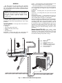
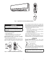
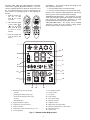
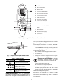
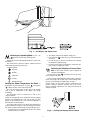
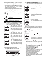
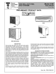
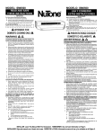
OWNER’S MANUAL
High-Wall Fan Coil Unit
CONTENTS
Page
GENERAL. . . . . . . . . . . . . . . . . . . . . . . . . . . . . . . . . . . . . . .2,3
OPERATING MODES . . . . . . . . . . . . . . . . . . . . . . . . . . . . 2
REMOTE CONTROL. . . . . . . . . . . . . . . . . . . . . . . . . . . . . 2
OPERATION . . . . . . . . . . . . . . . . . . . . . . . . . . . . . . . . . . . 3-9
REMOTE CONTROL OPERATION . . . . . . . . . . . . . . . . 3
INDOOR UNIT DISPLAY . . . . . . . . . . . . . . . . . . . . . . . . . 5
EMERGENCY OPERATION . . . . . . . . . . . . . . . . . . . . . . 5
PRESSING THE ON/OFF BUTTON. . . . . . . . . . . . . . . . 5
SELECTING AN OPERATING MODE. . . . . . . . . . . . . . . 6
SETTING THE TEMPERATURE SET POINT . . . . . . . 6
SELECTING THE DIRECTION
OF LOUVER POSITION. . . . . . . . . . . . . . . . . . . . . . . . 6
SELECTING THE FAN SPEED . . . . . . . . . . . . . . . . . . . . 7
USING THE TURBO SETTING . . . . . . . . . . . . . . . . . . . 7
USING THE ECONOMICAL SETTING . . . . . . . . . . . . 7
SETTING THE ON TIMER. . . . . . . . . . . . . . . . . . . . . . . . 7
SETTING THE OFF TIMER. . . . . . . . . . . . . . . . . . . . . . . 8
SETTING THE DAILY TIMER . . . . . . . . . . . . . . . . . . . . 8
SETTING THE SLEEP TIMER . . . . . . . . . . . . . . . . . . . . 8
USING THE IONIZER FUNCTION . . . . . . . . . . . . . . . . 9
REMOTE CONTROL ADDRESS SELECTION . . . . . 9
Page
RESETTING THE REMOTE CONTROL . . . . . . . . . . . 9
OPERATING CONDITIONS . . . . . . . . . . . . . . . . . . . . . . 9
TIME DELAY . . . . . . . . . . . . . . . . . . . . . . . . . . . . . . . . . . . 9
MINIMUM OPERATION TIME . . . . . . . . . . . . . . . . . . . 9
HEATING FEATURES. . . . . . . . . . . . . . . . . . . . . . . . . . . . 9
DEFROST OPERATION . . . . . . . . . . . . . . . . . . . . . . . . . . 9
AUTO RECOVERY . . . . . . . . . . . . . . . . . . . . . . . . . . . . . . 9
INDOOR UNIT FROST PREVENTION IN
COOLING AND DEHUMIDIFICATION
MODE. . . . . . . . . . . . . . . . . . . . . . . . . . . . . . . . . . . . . . . . 9
CLEANING, MAINTENANCE AND
TROUBLESHOOTING . . . . . . . . . . . . . . . . . . . . . . . . . .9-11
PERIODIC MAINTENANCE . . . . . . . . . . . . . . . . . . . . . . 9
CLEANING THE COIL . . . . . . . . . . . . . . . . . . . . . . . . . . . 9
AIR FILTERS. . . . . . . . . . . . . . . . . . . . . . . . . . . . . . . . . . . 10
IONIZER . . . . . . . . . . . . . . . . . . . . . . . . . . . . . . . . . . . . . . . 10
INDOOR UNIT FRONT PANEL . . . . . . . . . . . . . . . . . . 10
PREPARING FOR A LONG SHUTDOWN PERIOD. . 10
SYSTEM OPERATION CHECK LIST . . . . . . . . . . . . . 10
ENERGY SAVING RECOMMENDATIONS. . . . . . . . 10
TROUBLESHOOTING . . . . . . . . . . . . . . . . . . . . . . . . . . . 10
Manufacturer reserves the right to discontinue, or change at any time, specifications or designs without notice and without incurring obligations.
Catalog No. OM38-40-7
Printed in U.S.A.
Pg 1
Edition date: 3-08
Replaces: OM38/40-6
AUTO — In Auto mode, the system will automatically cool or
heat the room according to the user selected set point.
If the room temperature is 2° F lower than the set point, the
system will operate in Heating mode. If the room temperature
is 2° F higher than the set point, the system will operate in
Cooling mode.
HEATING — In Heating mode, the system heats and filters
room air.
COOLING — In Cooling mode, the system cools, dries and
filters room air.
DEHUMIDIFICATION — In Dehumidification mode, the
system dries, filters and slightly cools room air temperature.
This mode does not take the place of a dehumidifier.
NOTE: Two settings are available for use with selected modes.
The Turbo setting provides maximum capacity. The Economical setting provides quiet, energy saving operation. Cooling
and Heating modes can be operated in either the Turbo or
the Economical setting. The Dehumidification mode can be
operated in the Turbo setting, and the Auto mode can be
operated in the Economical setting. See the Using the Turbo
Setting or Using the Economical Setting sections for more
information.
GENERAL
The high wall fan coil unit provides quiet, maximum
comfort. In addition to cooling and/or heating, the high wall
fan coil unit matched with an outdoor condensing unit will
filter and dehumidify the air in the room to provide maximum
comfort. See Fig. 1.
IMPORTANT: The high wall fan coil unit should be
installed by authorized personnel only, using approved
tubing and accessories. If technical assistance, service
or repair is needed, contact the installer or call
1-800-227-7437.
The high wall fan coil unit can be set up and operated from
the remote control (provided). See Fig. 2. If the remote is
misplaced, the system can be operated from the “Auto” setting
on the unit.
Operating Modes — The high wall fan coil unit has 5
operating modes:
• Fan only
• Auto (heat pump models only)
• Heating (heat pump models only)
• Cooling
• Dehumidification
FAN ONLY — In Fan Only mode, the system filters and
circulates room air without changing room air temperature.
1
2
Remote Control (Fig. 2-6) — The remote control
transmits commands to set up and operate the system. The
controller has a window display panel that shows the current
system status. The controller can be secured to a surface when
used with the mounting rack provided. See Fig. 2.
3 4
5
A
B
1
2
3
4
5
6
6
Fig. 1 — Indoor and Outdoor Unit Components
2
—
—
—
—
—
—
—
—
LEGEND
Outdoor Unit
Indoor Unit
Automatic Swinging Louver
Air Filters
Remote Control Signal Receiver
Unit Operating Status Indicators
Interconnecting Tubing
Condensate Drain
Fig. 2 — High Wall Fan Coil Unit and Remote Control
unit to malfunction. Batteries should only be changed after
turning the unit off. The average battery life during normal
use is approximately one year. If the air conditioner does not
operate normally after replacing the batteries, refit the batteries
and press the reset button again after 5 seconds.
To install batteries:
1. Remove battery compartment cover by pushing the tab
up and removing it from the remote.
2. Insert batteries being sure to follow polarity markings
inside battery compartment.
3. Replace battery compartment cover.
NOTE: Replace batteries whenever “Low battery” indicator
appears on remote control display panel. See Fig. 4.
DISPLAY SCREEN — There are five operating mode indicators that appear on the remote control display screen. See Fig. 4.
Handle the controller with care and avoid getting the controller wet. Damage to the device may result.
IMPORTANT: The remote control can operate the unit
from a distance of up to 16 ft as long as there are not any
obstructions.
The remote control can perform the following functions:
• Turn the system ON and OFF
• Select operating mode
• Adjust room air temperature set point and fan speed
• Set time periods for automatic system operation
BATTERY INSTALLATION — Two AAA 1.5-v alkaline
batteries (included) are required for operation of the remote
control. See Fig. 3 for battery location.
After new batteries have been inserted, press the reset
button with a paper clip or the tip of a pen. Do not use old
batteries or batteries of different types, as this may cause the
OPERATION
Remote Control Operation — The remote control
has 3 buttons (see Fig. 5) used for operating and controlling the
system:
•
— changes operating mode
•
— adjust temperature
•
— turns the system on or off.
NOTE: When transmitting a command from the remote
control to the unit, be sure to point the controller toward the
right side of the unit. See Fig. 6. The unit will confirm receipt
of a command by sounding an audible beep.
IMPORTANT: If no changes are made within 10 seconds, the remote control will return to its previous
setting.
Fig. 3 — Location of Batteries on Remote Control
3
SETTING THE TIME ON THE REMOTE CONTROL
(Current Time Adjusting C and Reset Buttons) — Press current time adjusting button C to adjust the current time. Press
the reset button with the tip of a pen or a paperclip if the remote control is not operating properly or after replacing the
batteries.
1. With the remote control ON or OFF,
press C for at least
5 seconds.
FAN SPEED — To select the Fan mode and change the Fan
Speed, follow the steps below:
1. Press the Mode button to select the Fan mode.
2. Press the Fan Speed button to select desired fan speed.
NOTE: If unit is operating in Dehumidification mode the fan
will only operate in low speed and cannot be changed.
TEMPERATURE SETTINGS — The temperature set point
can be easily changed by pointing the controller toward the unit
and pressing the increase/decrease temperature set point
buttons until the desired temperature appears on screen.
AIRFLOW DIRECTION — The louvers can be manually
operated by pressing the Louver button to change airflow
direction. Refer to Table 1 for louver positions.
2. The current hour flashes. Press either
or
to set the current
hour. Press C again
to move to set the
minutes.
3. Once the current time
is set, press C to confirm it.
1
3
2
5
4
7
6
9
8
11
10
17
12
13
15
16
14
7.
8.
9.
10.
11.
12.
13.
14.
15.
16.
17.
1. Operating mode (from left to right)
Fan only
Heating (heat pump models only)
Automatic (heat pump models only)
Cooling
Dehumidification
2. Signal transmission symbol
3. Temperature set point selected
4. Address selected
5. Temperature unit of measurement (°C or °F)
6. Unit configuration
Low Battery indicator
Louver position
Fan speed
Turbo setting
Economical setting
ON timer selected
Night timer active
DAILY timer active (Everyday)
ON timer and OFF timer or current time
OFF timer selected
Ionizer active
Fig. 4 — Remote Control Display Icons
4
Display readout
A.
Mode selection button
B.
ON/OFF button
C.
Increase temperature button
D.
Decrease temperature button
E.
Fan speed selection button
F.
Turbo setting button
G.
Economical setting button
H.
Louver control button (Flap)
I.
ON timer button
J.
DAILY timer button (Everyday)
K.
Cancel timer button / Current time
button
L.
OFF timer button
M.
Sleep timer button (night)
N.
Ionizer button
O.
Reset button
Fig. 5 — Operating Mode Indicators on Remote Control
active. The Orange light is illuminated during timer mode. The
Green light is illuminated during operation.
Emergency Operation — When the remote control is
lost or damaged or the batteries are exhausted, the EMER.
button can be used to run the unit.
Press the EMER. button once briefly when the system is off.
To stop emergency operation, push the EMER. button again
or operate the remote control.
The set conditions of emergency operation are as follows:
• Preset set point: 77 F
• Fan speed: AUTO
• Timer mode: Disabled
• Discharge air direction: Pre-set position based on operation in “Cool” or “Heat” mode.
Fig. 6 — Proper Positioning of Remote Control
Table 1 — Louver Positions
SYMBOL ON
REMOTE CONTROL
Pressing the On/Off Button — When the
air conditioner is not in operation, the remote
control readout will display the time of day only.
DESCRIPTION
Louver position will be set automatically.
Louver will be set to the preset position
according to the operation mode.
Press the On/Off button to start the unit.
The unit will start in the last operating mode.
Press button On/Off to stop the unit.
All indicator lights on the unit will go out, and the remote
control will display only the current time.
If the unit does not stop, turn the control on (by pressing the
On/Off button) and repeat the operation.
NOTE: If the On/Off button is pressed too soon after a stop,
the compressor will not start for 3 to 5 minutes due to the
inherent protection against frequent compressor cycling. The
unit will only emit an audible beep when the signals are
received correctly.
The louver can be set to one of
six different airflow directions.
The louver will continuously swing
up and down. The “swing” setting will
provide optimal, even air distribution
in the room.
Indoor Unit Display (Fig. 7) — The indoor unit display has three LED indicators at the lower right hand portion of
the unit. The Blue light is illuminated when the ionizer is
5
Fig. 7 — Unit Display and Switch Panel
2. The display will show the channel setting (CH).
3. Press the mode
button once to go to the Temperature
(tu) screen.
4. Use the increase or decrease set point arrows to change
the temperature display setting.
5. Press the louver button to transmit the temperature display setting to configure the remote.
Selecting an Operating Mode — Use the
button to select the unit operating mode.
Repeatedly press the Operating Mode button to select available modes.
The chosen mode is shown as follows, while the unit will
acknowledge signal receipt with a beep.
Indicated symbol:
Fan Only
Selecting the Direction of Louver Position — The airflow direction can be adjusted to
Heating
optimize air distribution.
Press the louver button
repeatedly to choose one of the
louver positions. See Table 1.
Automatic
Cooling
In the Cooling, Dehumidification and Fan Only mode, the
louver will swing in the cooling range. In the Heating mode,
the louver will swing in the heating range. See Fig. 8.
NOTE: Always use the remote control to adjust the louver
position, otherwise abnormal operation may occur. If the
louver is manually adjusted out of its range, turn the unit off
and then on again.
Dehumidification
Setting the Room Temperature Set Point —
Pressing the increase temperature set point
and decrease
buttons will raise or lower the temperature.
The unit will confirm signal receipt with a beep, and the
value of the set temperature on the display will change
accordingly.
The temperature can be set between 63 F and 90 F at
1 degree intervals.
NOTE: In Cooling mode, if the temperature selected is higher
than the room temperature the unit will not start; the same
applies for the Heating mode, if the selected temperature is
lower than the room temperature.
The remote control can be set to display the temperature in
degrees Fahrenheit or degrees Celsius. To change the temperature setting, complete the following steps while the unit is off:
1. Press the decrease set point button and the louver button
simultaneously for 5 seconds.
Fig. 8 — Cooling and Heating Louver Position
6
LEFT AND RIGHT CONTROL — To adjust the direction of
the discharge air to the left or right, adjust the vertical guide
vane with the handle after opening the louver. See Fig. 9.
NOTE:
• Do not set the louver to position
for long periods of
time, because this position minimizes air circulation
resulting in uneven room temperature.
• Do not adjust the louver manually during SWING operation because it may damage the air swing mechanism.
• For maximum cooling or heating capacity, please louver
to position
.
E
energy saving operation in Cooling, Heating and Auto
modes, press the Economical Setting button E. On the
display, the Economical Setting icon E will appear.
1. Economical Cooling mode:
The indoor fan and compressor operate
at a minimum speed for maximum energy savings.
Selecting the Fan Speed — The fan speed
can be selected by pressing the fan speed button
.
SYMBOL
Using the Economical Setting — For quiet,
2. Economical Heating mode:
The indoor fan and compressor operate
at a minimum speed for maximum energy savings.
DESCRIPTION
Low speed.
Medium speed.
High speed.
3. Economical Auto mode:
Unit operates in Economical Cooling
mode or Economical Heating mode
depending on the room temperature
and set point.
Automatic (fan will automatically switch to the
appropriate speed for optimum comfort).
Using the Turbo Setting — For maximum
capacity while in Cooling, Dehumidification and Heating modes, press the Turbo Setting button
. On the
display, the Turbo Setting icon
will appear.
1. Turbo Cooling mode performs the
turbo cooling operation until room temperature reaches 63 F or 20 minutes after pressing the Turbo Setting button.
While in Turbo Cooling mode, indoor
fan speed is high and compressor speed
is over-rating speed to obtain maximum
cooling capacity.
During the Economical setting, the room temperature and
louver position can be set by using the remote control. Fan
speed cannot be changed while in the Economical setting.
Press
,
or E to cancel the economical setting.
Setting the ON Timer
2. Turbo Heating mode performs the
turbo heating operation until room
temperature reaches 90 F or 20 minutes
after pressing the turbo setting button.
While in Turbo Heating mode, the
indoor fan and compressor operates in
high speed in order to obtain maximum
heating capacity.
1. ON TIMER button
Press the
, even if the unit is off.
The relevant icon and time figure will
start to flash.
If 10 seconds have elapsed and no
button is pressed, the remote control
returns to the previous setting without
making any changes.
2. Setting the ON time with
.
3. Turbo Dehumidification mode performs the dehumidification operation
until room temperature is under 63 F or
3 hours after pressing the turbo setting
button. While in Turbo Dehumidification mode, indoor fan speed operates in
low speed in order to remove humidity
more effectively.
When the unit is ON, the only possible selection is the
start-up time. The Operating mode and set point remain
the same as the current operation.
To select the start-up time when the unit is off, use
.
First select the hours and confirm by pressing
. Then
select the minutes using either
or
.
During the turbo setting, room temperature and fan speed
cannot be changed using the remote controller.
Press
,
or E to cancel turbo setting mode.
To finish setting the time, press
again.
3. Choose the unit Operating mode.
To select the operating mode, use the
button. Once
the operating mode has been selected, press
.
The icon of the selected mode will stop flashing.
4. Select the desired set point temperature.
To select the desired temperature, use either
or
.
Push
to confirm the selection. The set point numbers
will stop flashing.
Fig. 9 — Using the Vertical Guide Vane
7
For everyday operation to start at 5:30 P.M. and stop at
10:30 P.M. complete the following steps:
1. Set the ON timer for 5:30 P.M.
2. Set the OFF timer for 10:30 P.M.
3. Press the DAILY timer button
.
5. Fan speed:
Choose the fan speed, using
. When the selection has
been completed, press button
for confirmation. The
fan speed icon will stop flashing.
6. Louver positioning:
Use
, to select desired louver position. Press
for
confirmation. Now all icons are fixed on display. To cancel selections made up to this point, push C; to cancel all
of the selected options once the timer has been set,
push
and then C. The ON Timer settings are now
complete.
PM
Setting the Off Timer — Set the Off Timer to
select a time for the system to turn off.
PM
1. Press the Off Timer button.
The Off timer icon and numbers for a
time selection flash.
NOTE: This function can be set even if
the remote control is OFF.
2. Setting the Off time (buttons
and
).
CANCELLING THE ON, OFF AND DAILY TIMER
SETTINGS — To cancel the ON or OFF timer setting, press
the following buttons in order:
1. Button
or
;
2. Button C.
To deactivate the Daily timer function, press
.
To set the Off time, press either button
or
.
To move from hour to minute, press
.
Press
setting.
PM
NOTE: Everyday operation will remain
active until one of the two timers (ON
or OFF) is active.
again to confirm Off time
Setting the Sleep Timer — Press this button
to set the SLEEP timer with the system on. The icon
will appear on the display.
This procedure permits setting the remaining unit operating
time until the Sleep mode is entered.
1. “1:hr” will be displayed together with the
icon.
Setting the DAILY Timer — Push the button
when the ON or OFF timer is active. The
icon will appear on display.
In this way the ON and OFF timer settings will be repeated
every day.
To deactivate the daily function, press
again.
EXAMPLE 1: Combining the ON, OFF and DAILY timer
features.
To start the unit at 5:30 P.M. and stop at 10:30 P.M. for one
day only, complete the following steps:
1. Set the ON timer for 5:30 P.M.
2. Set the OFF timer for 10:30 P.M.
3. Select desired operating mode (
).
2. Press
. The display will show the
following settings in sequence: 1:hr, 2:hr,
3:hr, 4:hr, 5:hr, 6:hr, 7:hr, 8:hr and 9:hr.
3.
PM
PM
Once the remaining operating hours have been selected
with either button
or
, press the
button to
confirm.
4. When the SLEEP timer is set, the unit will control the set
temperature to avoid overcooling or overheating during
operation. The set temperature will change as in Fig. 10.
PM
EXAMPLE 2: To stop operation at 10:30 P.M. and start again
at 7:30 A.M. with the same operating mode, complete the following steps:
1. Set the OFF timer for 10:30 P.M. while the system is
operating.
2. Set the ON timer for 7:30 A.M.
AM
PM
8
Time Delay — If unit operation is started after the power
1 F
F
is turned off, there will be a 3-minute time delay until the
compressor turns on.
When heating operation starts, hot air delivery may be
delayed due to a warm-up period.
1 F
1 F
1 F
Minimum Operation Time — In normal operation,
there is a minimum operation time of 5 to 7 minutes between
the compressor turning on and turning back off.
Heating Features — If the unit starts in Heating mode,
there may be a preheating period before the unit is ready to
deliver warm air.
(Cooling only or Dehumidification mode)
Defrost Operation — In heating mode, if the outdoor
coil is frosted, the indoor fan and outdoor fan will turn off
while system removes the frost on the outdoor coil.
The system will automatically revert to normal operation
when frost is removed from the outdoor unit.
°F
2 °F
2 °F
Auto Recovery — If the power fails while the unit is
operating, the unit memorizes the operating condition, and it
will start operation automatically when the power is restored.
2 °F
Indoor Unit Frost Prevention in Cooling and
Dehumidification Mode — If the unit operates at a
low ambient temperature, frost may appear on the indoor coil.
If the indoor coil temperature is near 32 F, the compressor’s
speed is reduced or stopped to protect the unit from frost.
(Heating mode)
Fig. 10 — Set Temperature Levels
CLEANING, MAINTENANCE
AND TROUBLESHOOTING
Using the Ionizer Function — The ionizer
helps to eliminate odors in the conditioned space.
1. Press
function.
to activate the Ionizer
To avoid the possibility of electric shock, always turn off
power to the system before performing any cleaning or
maintenance to the system. Turn off the outdoor disconnect
switch located near outdoor unit. Be sure to disconnect
indoor unit if on a separate switch.
2. Press
again to turn off Ionizer
function.
Remote Control Address Selection — If two indoor units are in the same room, one remote control can be
linked to one indoor unit, and the other remote control to the
other indoor unit, or both indoor units can be controlled with a
single remote control.
For more information, refer to the installation instructions.
Operating the system with dirty air filters may damage the
indoor unit and could cause reduced cooling performance,
intermittent system operation, frost build-up on indoor coil
or blown fuses.
Resetting the Remote Control — If the remote con-
Periodic Maintenance — Periodic maintenance is
recommended to ensure proper operation of the unit. Recommended maintenance intervals may vary depending on the
installation environment, e.g., dusty zones, etc. Refer to
Table 2.
trol is not functioning properly it can be reset by pressing the
reset button with a paper clip or tip of a pen.
Operating Conditions — Temperature ranges suitable
for unit operation are as follows.
MODE
Cool
Heat
Dehumidification
INDOOR
(°F)
59-90
Max. 81
59-90
OUTDOOR
(°F)
14-115
14- 75
14-115
The coil fins are very sharp. Use caution when cleaning
the coil fins to prevent unit damage and to avoid personal
injury.
Cleaning the Coil — Clean the coil at the beginning of
each cooling season, or when necessary. Use a vacuum cleaner
or a long-bristle brush to avoid damage to the coil fins.
If the unit operates above 59 to 90 F maximum temperature
conditions for a long period of time, system diagnostics may
modify the system operation to prevent damage to the system.
9
Air Filters — Remove and clean the air filters once a
Preparing for a Long Shutdown Period —
month.
NOTE: If air filters show signs of excessive wear or are torn,
they must be replaced. Contact your local dealer for replacement filters.
1. Open front panel on unit.
2. Pull filters down to remove.
3. Vacuum filters.
4. Clean with warm water.
5. Shake filter to remove excess water and dry thoroughly.
6. Replace filter by sliding filter behind front grille until filter snaps in place.
Clean the filters and reposition them in the unit. Operate the
unit in Fan only mode for 12 hours to dry all internal parts.
Turn main power supply off and remove batteries from the
remote control.
System Operation Check List — The items out-
lined in the following list will help to assure proper system
operation:
• Be sure unit is connected directly to electrical supply.
• Replace both remote control batteries at the same time
when the Low Battery indicator appears.
• Point the remote control toward the unit display panel
when transmitting a command.
• Keep doors and windows closed while unit is operating.
• Close air vents in unoccupied rooms to save electricity.
• Contact an authorized service representative if a problem
arises that cannot be easily resolved.
• Do not perform cleaning or maintenance activities while
unit is on.
• Keep display panel on unit away from direct sunlight and
heat as this may interfere with remote control transmissions.
• Do not block air intakes and outlets on the indoor or outdoor units.
When cleaning the front panel, do not use water hotter than
105 F and do not pour water onto the fan coil.
Do not use abrasive or petroleum based cleaners as they
may damage the front panel.
Ionizer — Clean the ionizer with a brush every four months.
Energy Saving Recommendations — The follow-
ing recommendations will add greater efficiency to the ductfree system:
• Select a comfortable thermostat setting and leave it at
chosen setting. Avoid continually raising and lowering
the setting.
• Keep unit filter clean. Frequent cleaning may be necessary depending on indoor air quality.
• Use drapes, curtains or shades to keep direct sunlight
from heating room on very hot days.
• Do not obstruct front grille air intake on front panel.
• Turn on air conditioning before indoor air becomes too
uncomfortable.
Disconnect the unit from the main power supply prior to
cleaning or performing maintenance on the ionizer. Serious
personal injury could result.
1. Unscrew and lift the ionizer cover.
2. Brush the needles on the base of the ionizer.
3. Close the cover and tighten the screw.
Indoor Unit Front Panel — To clean the front panel on
the indoor unit, wipe the outside with a soft, dry cloth. If necessary, a mild liquid detergent can be applied and wiped off with
a dry cloth.
Troubleshooting — Refer to Tables 3 and 4 before contacting your local dealer.
Table 2 — Periodic Maintenance
INDOOR UNIT
Clean Air Filter*
Clean Drain Pipe
Change Remote Control Batteries
Clean Ionizer
OUTDOOR UNIT
Clean Outdoor Coil from Outside
Clean Outdoor Coil from Inside†
Blow Air Over Electric Parts†
Check Electric Connection Tightening†
Clean Fan Wheel†
Check Fan Tightening†
Clean Drain Pans†
EVERY MONTH
●
EVERY MONTH
EVERY 4 MONTHS
●
●
EVERY 4 MONTHS
●
*Increase frequency in dusty zones.
†Maintenance to be carried out by qualified service personnel. Refer to the Installation Manual.
10
EVERY YEAR
●
EVERY YEAR
●
●
●
●
●
●
Table 3 — Troubleshooting
PROBLEM
Unit/System Does Not Work
Cooling is Not Working Properly
Heating is Not Working Properly
Unit Stops During Operation
POSSIBLE CAUSE
• The circuit breaker has tripped or a fuse has
blown.
• Power failure.
• Green or Orange LED is flashing on and off,
which could indicate an indoor or outdoor unit
fault.
• Voltage is too low.
• The filter is blocked with dust.
• Temperature is not set properly.
• A window or door is open.
• The outdoor unit is obstructed.
• The fan speed is too low.
• The operation mode is in Fan or Auto instead of
Cool.
• The filter is blocked with dust.
• Temperature is set too low.
• A window or door is open.
• The outdoor unit is obstructed.
• The Off timer is not operating correctly.
• Green or Orange LED is flashing on and off,
which could indicate an indoor or outdoor unit
fault.
SOLUTION
• Reset the circuit breaker or replace the fuse with the
specified replacement fuse.
• Restart operation when the power is restored.
• Call your service representative.
• Call your service representative.
• Clean the air filter.
• Check the temperature and reset if necessary.
• Close the window or door.
• Remove the obstruction.
• Change the fan speed selection.
• Change the operating mode to Cool or reset the unit.
• Clean the air filter.
• Check the temperature and reset if necessary.
• Close the window or door.
• Remove the obstruction.
• Restart the operating mode.
• Call your service representative.
LEGEND
LED — Light Emitting Diode
Table 4 — Unit Protection Devices
TYPE OF PROTECTION
EFFECT OF PROTECTION
Indoor Coil High Temperature Protection
Compressor speed slow down or off
Indoor Coil Freeze Up Protection
Compressor speed slow down or off
Discharge Gas High Temperature Protection
Compressor speed slow down or off
Frequent Compressor Cycling
Compressor time delay
OPERATING MODE
Heating and Auto mode at high
outdoor temperatures
Cooling, Dehumidification and Auto mode
at low outdoor temperatures
Cooling, Heating, Dehumidification and
Auto mode outdoor temperatures
All
During heating operation the unit may defrost to remove
ice that might collect on the outdoor unit. During defrost,
the indoor fan will automatically stop, the louver will be
fixed at a horizontal position and can not be changed until
the defrost cycle is completed. Forcing the louver to
change its position during defrost could result in equipment
damage.
Fill out the following to save time on any future service calls.
Dealer’s Name _____________________________________________________________________________________________
Address ___________________________________________________________________________________________________
Telephone _________________________________________ Purchase Date _________________________________________
Indoor Model #_____________________________________ Outdoor Model #_______________________________________
Indoor Serial # _____________________________________ Outdoor Serial # _______________________________________
11
Manufacturer reserves the right to discontinue, or change at any time, specifications or designs without notice and without incurring obligations.
Edition date: 3-08
Carrier Copyright 2008
Catalog No. OM38-40-7 Printed in USA
Pg 12
Replaces: OM38/40-6