1
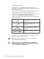
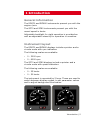
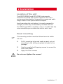
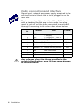
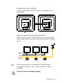
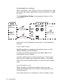
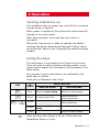
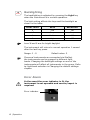
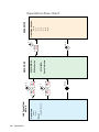
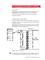
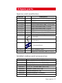
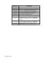
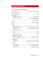
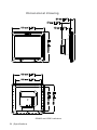
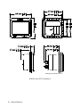
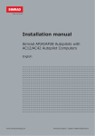
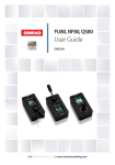
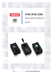
Manual Simrad IS70/IS80 RPM Indicators RPM70 and RPM80 Speed Indicators SP70 and SP80 English www.simrad-yachting.com A brand by Navico - Leader in Marine Electronics Manual Simrad IS70/IS80 RPM indicators RPM70 and RPM80 Speed indicators SP70 and SP80 English Document no: 20243861 Revision: A Date: April 2009 The original language for this document is English. In the event of any discrepancy between translated versions and the English version of this document, the English document will be the official version. To the best of our knowledge, the content in this publication was correct at the time of printing. As we are continuously improving our products we retain the right to make changes to the product and the documentation at any time. Updated manuals are available from our website www.simrad-yachting.com, and are free to download. © Copyright 2009 by Navico Holding AS. About this manual This manual is a reference guide for installing and operating the Simrad RPM70/RPM80 indicators and SP70/ SP80 speed indicators. The manual does not include installation procedures for sensors that can be connected to the system. In this manual, names of modes and keys are written in boldface (e.g. User setup, Mode/Setup key). In the illustrations throughout the manual the following symbols are used: Time indication (1, 3, 5 or 10 seconds) 3s 3s SELECT 3s MODE SETUP + SELECT SELECT Single key press with time indication Combined key press with time indication Repeated key presses on single key Important text that requires special attention from the reader is emphasized as follows: Used to draw the reader’s attention to a comment or some important information. When necessary, used to warn personnel they should proceed carefully to prevent risk of injury and/or damage to equipment. 2 | RPM70/RPM80 and SP70/SP80 indicators Contents 1 Introduction................................................ 5 General information.......................................5 Instrument layout..........................................5 2 Installation.................................................. 7 Location of the unit........................................7 Panel mounting..............................................7 Cable connection and interface........................8 Securing the cables........................................9 Interconnecting instruments............................9 Installation setup......................................... 10 3 Operation.................................................. 11 Turning indicators on.................................... 11 Using the keys............................................. 11 Backlighting................................................ 12 Error Alarm................................................. 12 Maintenance................................................ 13 Operation flow chart..................................... 14 4 Changing the default settings.................... 15 General...................................................... 15 Light bank selection..................................... 15 5 Spare parts................................................ 17 Spares and auxiliaries................................... 17 SimNet cables and accessories...................... 17 RPM70/RPM80 and SP70/SP80 indicators | 3 6 Specifications............................................ 19 Technical specifications................................. 19 Dimensional drawing.................................... 20 4 | RPM70/RPM80 and SP70/SP80 indicators 1 Introduction General information The RPM70 and RPM80 instruments present you with the engine r/min. The SP70 and SP80 instruments present you with the vessel speed in knots. Adjustable backlight for night operation is provided as well as adjustable intensity for operation in sunshine. Instrument layout The RPM70 and RPM80 displays include a pointer and a circular scale with rpm indication. The following scales are available: •• 0 - 3000 rpm •• 0 - 6000 rpm The SP70 and SP80 displays include a pointer and a circular scale with speed indication. The following scales are available: •• 0 - 25 knots •• 0 - 50 knots The instrument is operated by 2 keys. These are used to switch between display modes, to set parameter values and to adjust background illumination. Introduction | 5 Blank page 6 | Introduction 2 Installation Location of the unit The RPM70/RPM80 and SP70/SP80 instruments should be mounted with special regard to the unit’s environmental protection, temperature range and cable length. Refer to the Specifications chapter. Avoid mounting the unit where it is easily exposed to sunlight, as this may unintendedly overheat the unit. For RPM70 and SP70 a weather cover is included and the cover should be put on when the unit is not in use. Panel mounting The mounting surface must be flat and even to within 0.5 mm. 1 Drill 4 mounting holes and make a panel cut-out according to the drilling template included in the package 2 Use the supplied self tapping screws to secure the unit to the panel 3 Apply the front corners Do not over-tighten the screws! Installation | 7 Cable connection and interface Signal input, network and power supply are wired to the enclosed terminal block that is to be plugged in on the rear side. 1 The instrument is delivered with a 0.3 m SimNet cable with a standard SimNet plug in both ends. One plug must be cut off and the wires connected to terminals 3 through 6 according to the color codes shown below. TERMINAL NO SIGNAL TYPE COLOR 1 GND - Supply 2 VCC + Supply 12 - 24V DC 3 SimNet - H “High” signal line Yellow 4 SimNet - C Power source common Black 5 SimNet - L “Low” signal line Blue 6 SimNet - S Power source positive Red 7 NC Not connected - 8 NC Not connected - 9 NC Not connected - - Any voltages other than those specified in the product specification, page 19, may cause damage to the instrument. 8 | Installation Securing the cables Use the enclosed tie wrap to secure the cables to the instrument. Interconnecting instruments Interconnect a series of instruments by using a SimNet power cable with termination and T-joiners as illustrated below. Instrument Supply 12-24V SimNet 12V Supply (Red disk) SimNet T-joiner SimNet T-joiner SimNet T-joiner If the instruments are connected to other SimNet compatible products, refer to the manual for those products. Use only 12V as SimNet supply! Installation | 9 Installation setup After installation, the system must be configured to read the preferred input signal before the instrument is ready for use. The Installation Setup is accessed as shown in the illustration. INSTALLATION SETUP MAIN MODE RPM70/RPM80: RPM INDICATION SELECT 10 s MODE SETUP + SP70/SP80: SPEED INDICATION SELECT Pointer indication SIGNAL INPUT MODE SETUP 5s MODE SETUP + SELECT Save selection 1s SimNet Demo MODE SETUP + SELECT RESET Refer also to the Operation flow chart in the Operation section. Input signal type SimNet and Demo mode are selectable inputs on the RPM70/RPM80 and SP70/SP80. In Demo mode the instrument simulates data to be distributed on the SimNet. Use the right button to select signal type. The pointer position will change accordingly as shown in the table. Press both keys simultaneously to save the input signal type. Local SimNet reset When SimNet is selected as Signal Input you can reset the SimNet input sources by pressing both keys simultaneously. Press both keys for 5 seconds to return to Main mode. 10 | Installation 3 Operation Turning indicators on The indicators have no power key, and will be running as long as power is applied. When power is applied to the system the instrument will operate in the main mode. After approximately 3 seconds the instrument is operative. Before the instrument is ready to operate the default settings should be checked and changed if other values are preferred. Refer to the Changing the default settings chapter. Using the keys The instrument is operated by the 2 keys on the front. They are used to switch between display modes, to set values and to adjust the illumination as illustrated in the table below. Key presses or key combinations not indicated in the table have no effect. Refer also to Operation flow chart. KEY PRESS KEY MODE MODE SETUP MODE/ACTION DISPLAY MODE SETUP MODES SETUP 3 sec. Switch to User Setup Switch to main display SELECT Short Increase light level Select parameter Adjust parameter + SELECT 10 sec. 5 sec Save setting and return to Setup parameter Short Enter Installation Setup Return to main display Time out from User Setup is 10 sec. Time out from Installation Setup is 5 min. Operation | 11 SELECT Backlighting The backlighting is adjusted by pressing the Light key when the instrument is in normal operation. The light setting affects the keys and the backlight as shown in the table: LIGHT LEVEL KEYS BACKLIGHT 0 Low Off 1-7 Steps Steps 8 Medium Off 9 High Off Level 8 and 9 are for bright daylight. The instrument will return to normal operation 1 second after the last key press. Range: 0 - 9 Default value: 2 If several instruments are connected via SimNet, the instruments can be grouped in different light banks. Changing the backlight settings on one of the instruments will affect all instruments in the group. Refer to Light bank selection in Changing the default settings chapter. Error Alarm In the event the error indicator is lit, the instrument is not operable and service/repair is required. Error indicator 12 | Operation Maintenance The IS70/IS80 instruments are “repair by replacement” units, and the operator is therefore required to perform only a very limited amount of preventive maintenance. If the unit requires any form of cleaning, use fresh water and a mild soap solution (not a detergent). It is important to avoid using chemical cleaners and hydrocarbons such as diesel, petrol etc. If a weather cover is available this should be put on when the unit is not in use. Operation | 13 14 | Operation - Local SimNet reset Reset - Demo - SimNet Signal input INSTALLATION SETUP SETUP MODE SETUP MODE + + 5 min SELECT 5s SELECT 10 s Speed indication SP70/SP80: RPM Indication RPM70/RPM80: MAIN MODE SETUP MODE 10 s 3s - None - Gr 6 - Gr 5 - Gr 4 - Gr 3 - Gr 2 - Gr 1 - Simrad Light Bank Selection USER SETUP Operation flow chart 4 Changing the default settings General The factory default settings may all be changed in the User setup, accessed as shown in the illustration. Refer also to the Operation flow chart in the Basic Operation chapter. Light bank selection The light bank function is used to globally control light settings for a group of units that are connected via the SimNet network. By assigning several units to the same group, the light adjustment on one unit will be effective on the rest of the members in the same group. USER SETUP MAIN MODE 3s RPM70/RPM80: RPM INDICATION MODE SETUP Pointer LIGHT BANK SELECTION Light bank Save selection Simrad Group 1 SP70/SP80: Group 2 SPEED INDICATION Group 3 1s MODE SELECT SETUP + SELECT Group 4 Group 5 Group 6 When selecting a light bank a beep is heard None Default value: Simrad If you prefer one instrument to stay outside any group for independent light adjustment, you select “none”. Changing the default settings | 15 Blank page 16 | Changing the default settings 5 Spare parts Spares and auxiliaries Part no. Description 27107655 RPM80 instrument head, 0-3000 RPM 27107663 RPM80 instrument head, 0-6000 RPM 27107671 RPM70 instrument head, 0-3000 RPM 27107689 RPM70 instrument head, 0-6000 RPM 27107697 SP80 instrument head, 0-25 kts 27107705 SP80 instrument head, 0-50 kts 27107713 SP70 instrument head, 0-25 kts 27107721 SP70 instrument head, 0-50 kts Mounting kit including: - 4 screws - 6 corners - 1 terminal block 22096515 IS70 Weather cover 22098495 NMEA0183 Interface cable 2.5 m (8’) SimNet cables and accessories Part. no. Description 24005829 0.3 m (1’) SimNet cable (SDC:0.3M) 24005837 2 m (6.6’) SimNet cable (SDC:02M) 24005845 5 m (16.6’) SimNet cable (SDC:05M) 24005852 10 m (33’) SimNet cable (SDC:10M) 24005860 SimNet T-joiner (SDJ) (3p) 24006298 SimNet Multijoiner (7p) 24006306 SimNet Bulkhead T-connector 24005878 SimNet cable gland Spare parts | 17 Part. no. SimNet protection plug 24005894 SimNet termination plug 24005902 2 m (6.6’) SimNet power w/termination 24005910 2 m (6.6’) SimNet power w/o termination 24005936 AT10 Universal NMEA0183 converter 24005944 AT15 Active T-connector, IS15 24005928 SimNet cable protection cap 24005729 18 | Spare parts Description 24005886 SimNet to Micro–C male, 0,5 m cable that connects a SimNet product to a NMEA2000 network 24006199 SimNet to Micro-C female, 1 m cable that connects a NMEA2000 product to SimNet 24006363 SimNet cable, 5.5 m (18’), with 1 plug 6 Specifications Technical specifications Power supply.....................................12/24V DC (+30%, -10%) Power consumption........................................................< 5W SimNet network load....................................................... 1 NL Input signals: NMEA2000/SimNet........................................ 1 can channel Input mode selection:...........................NMEA2000/SimNet, Demo mode Weight:........................................................ 0.55 kg (1.21 lb) Material:........................................................ ASA/PC Luran S Color:........................................................................... Black Display: Dial RPM70/RPM80:............0 - 3000 r/min. or 0 -6000 r/min. Dial SP70/SP80:............................. 0 - 25 kts or 0 - 50 kts. Illumination:.................................... Adjustable in 10 steps Environmental protection: Front........................................................................ IP66 Back:....................................................................... IP20 Optional Back cover................................................... IP66 Safe distance to compass: Steering compass..................................... 0.40 m (1.32 ft.) Stand-by/Emergency distance.................... 0.20 m (0.66 ft.) Temperature: Operating:.............................. -15 to +70°C (+5 to +158°F) Storage:................................-40 to +80°C (-40 to +176°F) Climate Max 95% RH:.................................... Max 30 days per year Max 85% RH:............................................ Remaining days Max 75% RH:.......................................... Average per year Specifications | 19 Dimensional drawing 21 mm [0.83"] 47 mm [1.86"] 172 mm [6.78"] 172 mm [6.78"] 10 mm [0.37"] 152 mm [5.98"] 153 mm [6.02"] 136 mm [5.35"] 136 mm [5.35"] RPM80 and SP80 indicators 20 | Specifications 97 mm [3.8"] 115 mm [4.5"] 21 mm [0.8"] 47 mm [1.9"] 80 mm [3.1"] 75 mm [3.0"] With Optional IP66 Back Cover RPM70 and SP70 indicators 21 | Specifications 97 mm [3.8"] 90 mm [3.5"] 115 mm [4.5"] 90 mm [3.5"] Blank page 22 | Specifications RPM70/RPM80/SP70/SP80_OM_EN Doc.no. 20243861A *20243861A*