1
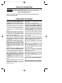
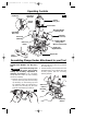
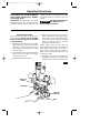
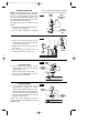
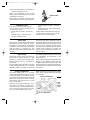
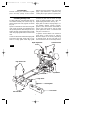
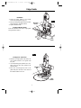
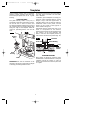
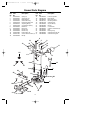
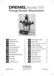
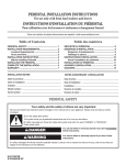
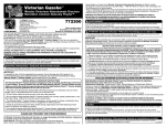
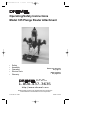
DM 2610920458 2-04
2/19/04
12:29 PM
Page 1
Operating/Safety Instructions
Model 335 Plunge Router Attachment
•
•
•
•
•
Safety
Assembly
Operation
Service Parts
Warranty
Parlez-vous français?
Voir page 12
¿Habla español?
Vea página 23
P.O. Box 1468
Racine, Wisconsin
1-800-437-3635
http://www.dremel.com
Dremel brand products are manufactured and sold by the
Dremel Division of Robert Bosch Tool Corporation
2 610 920 458 02/04
Printed in Taiwan
DM 2610920458 2-04
2/19/04
12:29 PM
Page 2
Power Tool Safety Rules
Read and understand all instructions. Failure to follow all instructions listed
! WARNING below, may result in electric shock, fire and/or serious personal injury.
SAVE THESE INSTRUCTIONS
Make sure to read and understand the Owner’s Manual for your Dremel Rotary Tool
Models 275, 285, 395 & 398.
Safety Rules for Routers
Hold tool by insulated gripping surfaces
when performing an operation where the
cutting tool may contact hidden wiring or
its own cord. Contact with a “live” wire will
make exposed metal parts of the tool “live”
and shock the operator. If cutting into existing walls or other blind areas where electrical wiring may exist is unavoidable, disconnect all fuses or circuit breakers feeding this
worksite.
Always make sure the work surface is
free from nails and other foreign objects.
Cutting into a nail can cause the bit and the
tool to jump and damage the bit.
Never hold the workpiece in one hand
and the tool in the other hand when in
use. Never place hands near or below
cutting surface. Clamping the material and
guiding the tool with both hands is safer.
Never place tool with bit protruding
through base on top of bench or work
surface. Lay the tool on its side or retract
the bit before setting on bench or work
surface. Protruding cutting bit may cause
tool to jump.
Always wear safety goggles and dust
mask. Use only in well ventilated area.
Using personal safety devices and working
in safe environment reduces risk of injury.
After changing the bits or making any
adjustments, make sure the collet nut and
any other adjustment devices are securely tightened. Loose adjustment device can
unexpectedly shift, causing loss of control.
Loose rotating components will be violently
thrown.
Never start the tool when the bit is
engaged in the material. The bit cutting
edge may grab the material causing loss of
control of the cutter.
Always hold the tool with two hands during startup. The reaction torque of the
motor can cause the tool to twist.
The direction of feeding the bit into the
material is very important and it relates to
the direction of bit rotation. When viewing the tool from the top, the bit rotates
clockwise. Feed direction of cutting must
be counterclockwise. NOTE: Inside and
outside cuts will require different feed direction. Refer to section on feeding the router.
Feeding the tool in the wrong direction causes the cutting edge of the bit to climb out of
the workpiece and pull the tool in the direction of the feed.
Always use the tool with the router base
securely attached and positioned flat
against material being cut. Having the
base securely positioned on the material
improves the stability and control of your
tool.
Never use dull or damaged bits. Sharp
bits must be handled with care. Damaged
bits can snap during use. Dull bits require
more force to push the tool, possibly causing the bit to break.
Never touch the bit during or immediately
after use. After use, the bit is too hot to be
touched by bare hands.
Never lay the tool down until the motor
has come to complete stop. The spinning
bit can grab the surface and pull the tool out
of your control.
Do not use the tool for drilling purposes.
This tool is not intended to be used with drill
bits.
Never use bits that have a cutting diameter greater than the opening in the base.
2
DM 2610920458 2-04
2/19/04
12:29 PM
Page 3
Operating Controls
Adjustment
Nut, Upper
Depth Stop
FIG. 1
Dremel
Rotary Tool
Release
Button
Speed Control
Mounting Wrench
& Storage Area
Adjustment
Nut, Lower
Hand Grip
(turn to lock)
Hand Grip
(stationary)
Collet Nut Wrench
Storage Area
(Wrench not included)
Shaft Lock
Button
Depth Scale
(English/Metric)
Edge Guide
Circle
Guide
Assembling Plunge Router Attachment to your Tool
ATTACHMENT FOR USE WITH DREMEL
ROTARY TOOL MODELs 275, 285, 395, &
398.
Disconnect the plug from
! WARNING the power source before
making any assembly, adjustments or
changing accessories. Such preventive
safety measures reduce the risk of starting
the tool accidentally.
2. Place tool into your router attachment
with the shaft lock button facing forward
as shown (Fig. 3).
3. Thread mounting nut clockwise onto the
threaded portion of your Rotary Tool and
securely tighten with the mounting
wrench provided.
FIG. 3
1. Remove collet nut, then remove housing
cap from your rotary tool and set housing
cap aside (Fig. 2). The housing cap must
be reinstalled when this attachment is
not used. Once housing cap has been
removed, reassemble the collet nut.
Shaft Lock
Button
Mounting
Nut
FIG. 2
Housing
Cap
Mounting
Wrench
3
DM 2610920458 2-04
2/19/04
12:29 PM
Page 4
Operating Instructions
ATTACHMENT FOR USE WITH DREMEL
HIGH SPEED ROTARY TOOL MODELS
275, 285, 395, & 398.
circular cuts. The router attachment comes
assembled ready for freehand or pilot bit
routing.
This Router Attachment is
! WARNING
not intended for use
under a router or saw table.
ATTENTION: This attachment will convert
Dremel Rotary Tool to a Plunge Router for
freehand routing, edging, grooving, and
Inserting the Router Bit
The router bits are held in the tool by a
collet system. The bit may be installed
before or after the rotary tool is installed
in the attachment.
1. Depress and hold the shaft lock button
while rotating the collet nut and shaft.
Continue to rotate the collet nut and
shaft until the lock engages and holds
the shaft (Fig. 4).
2. Use the wrench from your Dremel Rotary
Tool and turn the collet nut counterclockwise to loosen it.
3. Release the shaft lock button.
4. Insert the router bit into the collet as
deep as possible to ensure proper gripping of the bit and to minimize run out.
Do not insert the bit so far that bit flutes
touch the collet or collet nut to avoid
chipping or cracking the bit.
NOTE: Never place the tool with bit
protruding through base on top of bench or
work surface. Lay the tool on its side or
retract the bit before setting on bench or
work surface. Protruding cutting bit may
cause tool to jump.
5. Re-engage the shaft lock button and
tighten the collet nut; first by hand, then
using the wrench until bit is held securely.
FIG. 4
Shaft Lock
Button
Collet Nut
Collet Nut
Wrench
Base
4
DM 2610920458 2-04
2/19/04
12:29 PM
Page 5
Adjusting Routing Depth
NOTE: When making deep cuts, especially
plunge cuts away from the edge of the workpiece, it is recommended to make several
successive cuts progressively deeper using
the depth adjustment and depth scale rather
than making one single deep cut.
The depth limiter can be adjusted for two
depths.
1. Place your Dremel Rotary Tool and Router
assembly on the workpiece.
2. Turn the upper adjustment nut upward
and turn the lower adjustment nut downward so depth stop is free to move (Fig. 5).
Depth
Stop
FIG. 5
Upper
Adjustment
Nut
Lower
Adjustment
Nut
FIG. 6
3. Loosen the locking hand grip (Fig. 6).
Slowly lower the tool until the router bit
just touches the workpiece.
4. Tighten the locking hand grip to lock the
tool in place.
5. Press and hold the release button so
depth stop touches the router base.
1
Release
Button
Hand
Grip
FIG. 7
1st Routing Depth
6. Turn the depth stop upwards so that
measurement X equals the first desired
routing depth (Fig. 7).
NOTE: 1 turn equals .06" (1.5 mm)
7. Turn the upper adjustment nut down
snug against the router frame.
Depth
Stop
X
Upper
Adjustment
Nut
X
2nd Routing Depth
8. Turn the depth stop upwards so that
measurement X equals the second
desired routing depth. Make sure upper
adjustment nut turns with the depth stop,
so it rises away from router frame (Fig. 8).
9. Turn the lower adjustment nut up snug
against the router frame.
NOTE: The upper adjustment nut must
remain stationary when tightening the lower
adjustment nut.
FIG. 8
X
Depth
Stop
Lower
Adjustment
Nut
X
5
DM 2610920458 2-04
2/19/04
12:29 PM
Page 6
10.Press the release button to select the 1st
or 2nd routing depth (Fig. 9).
NOTE: The adjustment of each routing
depth should be checked with a trial cut and
re-adjusted as necessary.
When routing is complete, loosen the hand
grip and return the router to the top position.
FIG. 9
Release button
Feeding the Router
If the router is hard to control, heats up,
runs very slowly or leaves an imperfect cut,
consider these causes:
• Wrong direction of feed – hard to control.
• Feeding too fast – overloads motor.
• Dull bit – overloads motor.
• Cut too large for one pass – overloads
motor.
• Feeding too slow – leaves friction burns
on the workpiece.
Feed smoothly and steadily (do not force).
You will soon learn how the router sounds
and feels when it is working best.
Rate Of Feed
When routing or doing related work in wood
and plastics, the best finishes will result if
the depth of cut and feed rate are regulated
to keep the motor operating at high speed.
Feed the router at a moderate rate. Soft
materials require a faster feed rate than hard
materials.
The router may stall if improperly used or
overloaded. Reduce the feed rate to prevent
possible damage to the tool. Always be sure
the collet nut is tightened securely before
use. Always use router bits with the shortest
cutting length necessary to produce the
desired cut. This will minimize router bit runout and chatter.
Edge Forming
When edge forming, always use piloted or
bearing bits. The lower portion of a pilot
tipped bit is a shaft with no cutting edges.
Bearing guide bits have a ball bearing to
pilot the bit.
The pilot slides along the edge of the work
as the rotating blades make the cut, making
decorative edges. The edge on which the
pilot slides should be perfectly smooth since
any irregularities are transferred to the
shaped surface.
When routing a workpiece that requires edge
forming on the endgrain, always rout the
endgrain edge before routing the edges that
follow the grain. This minimizes the possibility of damage from any blowout at the end of
the endgrain.
Router Feed Direction
The router spindle turns in a clockwise
direction when viewed from above. For best
control and quality of cut, feed the tool into
the workpiece in the direction that the bit will
tend to pull itself into the wood. Incorrect
feed direction will cause the bit to try and
climb over the wood.
Feed the tool in direction shown here. If cutting around the edge of a square piece,
move the tool in a counterclockwise direction. If routing the inside surface as shown,
move in a clockwise direction (Fig. 10).
NOTE: Feed direction is extremely important
when using a pilot bit freehand on the edge
of a workpiece.
Router Feed direction
FIG. 10
Rout
End
Grains
First
Work
Bit Rotation
6
DM 2610920458 2-04
2/19/04
12:29 PM
Page 7
Tool Lubrication
Periodic cleaning and lubrication of guide
posts will keep plunge action smooth.
Depress and lock plunge router and evenly
apply a light lubricant (i.e. petroleum jelly,
cooking oil) to upper portion of guide posts.
Assembling the Edge Guide
For edge guide use, assemble guide rods into
tool holder assembly and secure using (2)
#10-24 square nuts and (2) guide rod knobs
(Fig. 11).
assembly on guide rods as shown. Set edge
guide at desired distance from cutter and
tighten edge guide knobs. (See Fig. 11 )
Edge guide is used for shaping edges, cutting rabbets, dadoes, mortise, tongues,
grooves, slots, and chamfers. Remember to
feed so the cutter tends to pull the edge
guide against the wood. A consistent feed
rate gives a smooth cut.
Square nut will slide in slots above the guide
rods. Guide rod knobs are assembled from
the top through holes down through nuts, and
against the rods. Fasten edge guide to guide
rods using edge guide knobs, and hex head
nuts.
In general, several shallow cuts should be
used when a deep groove is desired.
Maximum depth of cut will vary depending
on material used. Do not over feed to an
amount that the motor is noticeably slowed.
Locate hex head nuts underneath edge guide
and fasten with edge guide knob on top
surface of edge guide. Slide edge guide
Guide Rod Knob
Depth Adjustment
Screw
FIG. 11
Edge Guide Knob
Square Nuts
Guide Rods
Edge Guide
Finishing Nail
Circle Guide
Hex Head Nuts
7
DM 2610920458 2-04
2/19/04
12:29 PM
Page 8
Edge Guide
Installation
1. Install the edge guide to the plunge
router mounting blocks (Fig. 12).
2. Place parallel guide against work surface
with router bit in desired position.
3. Tighten thumbscrews.
FIG. 12
Mounting
Blocks
Routing with Edge Guide
Slide the flattened side of the edge guide
along the work surface.
Edge
Guide
FIG. 13
Routing Arcs and Circles
1 Remove the edge guide and attach the
circle guide bracket to the guide rods
(Fig. 13).
2. Use the finishing nail provided as a compass point. Set the circle guide for the
desired radius.
Finishing
Nail
3. Place the nail through the hole in the
guide and place the nail at the center of
the desired radius to be cut.
Edge
Guide
8
DM 2610920458 2-04
2/19/04
12:29 PM
Page 9
Templates
Using template patterns lets you duplicate
designs or letters uniformly time after time.
This technique requires the use of a guide
bushing.
Do not use a bit that may touch the inside of
the collar. Select a bit that is at least 1/16"
less in diameter.
In addition, special templates are easily prepared for cutting repeated patterns, special
designs, inlays, and other applications. A
template pattern may be made of plywood,
hardboard, metal or even plastic, and the
design can be cut with a router, jigsaw, or
other suitable cutting tool.
Remember that the pattern will have to be
made to compensate for the distance
between the router bit and the guide bushing
(the “offset”), as the final workpiece will
differ in size from the template pattern by
that amount, due to the bit position (Fig. 15).
GUIDE BUSHINGS
The guide bushing shown in (Fig. 14), is
essentially a plate with a collar which is inserted into the hole in base as shown, and
secured by threading a bushing plug on top of
the guide bushing. The guide bushing rides
along the edge of the template while the
router bit, protruding below, cuts into the
work.
FIG. 14
Bushing
Plug
FIG. 15
Router Bit
Collet Nut
Guide Bushing
Base
Templete
Pattern
Offset
Guide
Bushing
Workpiece
FREEHAND ROUTING
Many effects are gained by using the router
freehand with a small diameter bit. Usually the
craftsman pencils the outline or script he
desires onto the work and uses the pencil line
as a guide.
Base
ATTENTION: Be sure the thickness of the
template is the same or larger than the length
of bushing protruding below the base.
9
DM 2610920458 2-04
2/19/04
12:29 PM
Page 10
Dremel Parts Diagram
Ref.
No.
1
2
3
4
5
6
7
8
9
10
11
12
13
14
Part
No.
2610920042
2610920041
2610913432
2610920044
1603501018
2603345015
2604511008
2602305044
2610918203
2610918204
2610918206
2916011884
2910011191
2610358149
Description
Ref.
No.
Spring (2)
15
Guide Post. (2)
16
Depth Marker
17
Guide Plate Assy.
18
Knurled Thumbscrew
19
Adjusting Nut (2)
20
Compression Spring
21
Detent Pin
22
Hand Grip
23
Handle Cap
24
Handle Cap
25
Plain Washer (2)
26
Cheese Head Screws (2) 27
Nut (2)
Part
No.
2610920043
2610917203
2610920879
2610917207
2610917208
2615294964
2610915483
2610914826
2610914825
2615294965
2610920984
2610920985
2610920986
Description
Pressure Spindle
Edge Guide
Base plate Assy.
Mounting Wrench
Guide Rod (2)
Square Nut (2)
Nut (2)
Circle Guide
Clamp Screw #6-32 (4)
Nail
Bushing Plug
Guide Bushing 15/16"
Guide Bushing 5/8"
6
13
10
8
5
12
13
11
12
7
25
4
9
15
6
2
26
18
27
1
23
3
24
22
23
20
17
23
19
14
21
16
10
DM 2610920458 2-04
2/19/04
12:29 PM
Page 11
Dremel Limited Warranty
Your Dremel product is warranted against defective material or workmanship for a period of
one year from date of purchase. In the event of a failure of a product to conform to this
written warranty, please take the following action:
1. DO NOT return your product to the place of purchase.
2. Carefully package the product by itself, with no other items, and return it, freight prepaid,
along with:
A. A copy of your dated proof of purchase (please keep a copy for yourself).
B. A written statement about the nature of the problem.
C. Your name, address and phone number to:
UNITED STATES
CANADA
Dremel Service Center
Clinique d’ Outillage M.P.
4915 Twenty-First Street
3075 Boul, Hamel, Suite 107
Racine, Wisconsin 53406
Quebec City, Quebec G1P 4C6
Dremel Service Center
4631 E. Sunny Dunes
Palm Springs, CA 92264
Giles Tool Agencies
6520 Lawrence Avenue, East
Scarborough, Ontario M1C4A7
OUTSIDE CONTINENTAL
UNITED STATES
See your local distributor or write
to Dremel, 4915 Twenty-First
Street, Racine, Wisconsin 53406
Service d’Outlis ACM
2071 Victoria Street
St. Lambert, Quebec J4S 1H1
Westcoast Tool
Unit 2-285 East First Avenue
Vancouver, B.C. V5T 1A8
We recommend that the package be insured against loss or in transit damage for which we
cannot be responsible.
This warranty applies only to the original registered purchaser. DAMAGE TO THE PRODUCT
RESULTING FROM TAMPERING, ACCIDENT, ABUSE, NEGLIGENCE, UNAUTHORIZED
REPAIRS OR ALTERATIONS, UNAPPROVED ATTACHMENTS OR OTHER CAUSES UNRELATED TO PROBLEMS WITH MATERIAL OR WORKMANSHIP ARE NOT COVERED BY
THIS WARRANTY.
No employee, agent, dealer or other person is authorized to give any warranties on behalf of
Dremel. If Dremel inspection shows that the problem was caused by problems with material
or workmanship within the limitations of the warranty, Dremel will repair or replace the product free of charge and return product prepaid. Repairs made necessary by normal wear or
abuse, or repair for product outside the warranty period, if they can be made, will be charged
at regular factory prices.
DREMEL MAKES NO OTHER WARRANTY OF ANY KIND WHATEVER, EXPRESSED OR
IMPLIED, AND ALL IMPLIED WARRANTIES OF MERCHANTABILITY AND FITNESS FOR A
PARTICULAR PURPOSE WHICH EXCEED THE ABOVE MENTIONED OBLIGATION ARE
HEREBY DISCLAIMED BY DREMEL AND EXCLUDED FROM THIS LIMITED WARRANTY.
This warranty gives you specific legal rights and you may also have other rights which vary
from state to state. The obligation of the warrantor is solely to repair or replace the product.
The warrantor is not liable for any incidental or consequential damages due to any such
alleged defect. Some states do not allow the exclusion or limitation of incidental or consequential damages, so the above limitations or exclusion may not apply to you.
For prices and warranty fulfillment in the continental United States, contact your local Dremel
distributor.
Exportado por: Robert Bosch Tool Corporation Mt. Prospect, IL 60056 -2230, E.U.A.
Importado en México por: Robert Bosch, S.A. de C.V., Calle Robert Bosch No. 405,
Zona Industrial, Toluca, Edo. de México, C.P. 50070, Tel. (722) 2792300
11