1
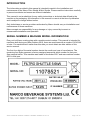
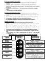
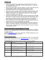
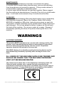
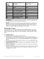
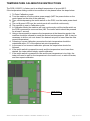
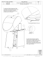
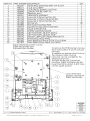
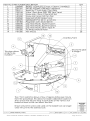
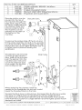
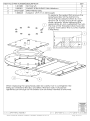
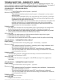
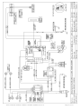
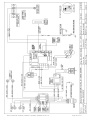
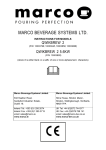
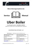
SERVICE MANUAL Marco Beverage Systems Ltd. 63d Heather Road, Sandyford Industrial Estate, Dublin 18, Republic of Ireland Ireland Tel: (01) 295 2674 Ireland Fax: (01) 295 3715 UK Tel: (0207) 274 4577 UK Fax: (0207) 978 8141 CONTENTS PAGE INTRODUCTION 3 SERIAL NUMBER & MACHINE MODEL INFORMATION 3 GENERAL DESCRIPTION 4 STANDARD INSTRUCTION MANUAL 5 BREW CALIBRATION INSTRUCTIONS 9 TEMPERATURE CALIBRATION INSTRUCTIONS 12 ASSEMBLY DRAWINGS PANEL REMOVAL CONTROL PCB ASSEMBLY LOWER INTERNAL PARTS UPPER INTERNAL PARTS DESCALING, ELEMENT AND PROBE REPLACEMENT SPRAYHEAD ASSEMBLY 13 14 15 16 17 18 TROUBLESHOOTING GUIDE 19 WIRING DRAWINGS FILTRO/MINI SHUTTLE 5.6kW SINGLE PHASE FILTRO/MINI SHUTTLE 2.8kW SINGLE PHASE FILTRO/MINI SHUTTLE 5.6kW THREE PHASE 20 21 22 SPARE PARTS LIST 23 Service Manual 1000650 1000651 1000655 1000656 23-01-12 Page 2 of 23 INTRODUCTION The information provided in this manual is intended to assist in the installation and maintenance of the Marco Filtro Shuttle & Mini Shuttle. Please read the instructions carefully to prevent accidents and ensure an efficient installation. This manual is not a substitute for any safety instructions or technical data affixed to the machine or its packaging. All information in this manual is current at the time of publication and is subject to change without notice. Only technicians or service providers authorised by Marco should carry out installation and maintenance of these machines. Marco accepts no responsibility for any damage or injury caused by incorrect or unreasonable installation and operation. SERIAL NUMBER & MACHINE MODEL INFORMATION Every unit will have a rating plate with a machine serial number. This manual is intended for machines built during and after October 2010, these are machines with a number 1010XXXX or later. For machines built earlier than this date you must obtain an older edition of this service manual. The first four digits of the serial number denote the month and year of manufacture. The remaining four digits represent a factory assigned sequential serial number for that year. See example below. This machine was made in November 2007 and was machine number 8521 in that year. Service Manual 1000650 1000651 1000655 1000656 23-01-12 Page 3 of 23 GENERAL DESCRIPTION 1000650 FILTRO SHUTTLE 5.6kW/ 1000655 MINI SHUTTLE 5.6kW Electrical Connection 5.6kW,230Vac c/w 1.5m flex Plumbing Fittings 0.75” BSP Pressure Food grade inlet hose supplied 5-50 psi (35-345 kPa) Dimensions Performance Height FILTRO SHUTTLE Height MINI SHUTTLE Width Depth (footprint on counter) Depth (depth of full machine & lid) Depth incl. Marco Urn 1700174 Hot Water (if tap is installed): Immediate Draw Off: Total Recovery rate at: 5.6KW 920mm 705mm 310mm 510mm 665mm 400ml + 0.9 litres/minute 0.9 litres/minute 1000651 FILTRO SHUTTLE 2.8kW/ 1000656 MINI SHUTTLE 2.8kW Electrical Connection 2.8kW,230Vac c/w 1.5m flex & moulded plug Plumbing As above Dimensions Performance As above Hot Water (if tap is installed): Immediate Draw Off: Total Recovery rate at: 2.8KW Service Manual 1000650 1000651 1000655 1000656 23-01-12 400ml + 0.45 litres/minute 0.45 litres/minute Page 4 of 23 STANDARD INSTRUCTION MANUAL (4 PAGES) INSTRUCTIONS FOR MODELS FILTRO SHUTTLE 5.6kW (P/N: 1000650 – 5.6kW and 1000651 – 2.8kW) (P/N: 1000650MJ – 3.6kW 200V) MINI SHUTTLE (P/N: 1000655 – 5.6kW and 1000656 – 2.8kW) Water Pressure : 5 - 50 psi (min.-max.)35 - 345 kPa (min.-max.) Water Flow Rate : 2 Litres per minute minimum. Marco Beverage Systems Limited. 63d Heather Road, Sandyford Industrial Estate, Dublin 18. Marco Beverage Systems Limited. Shire House, Strixton Manor, Strixton, Wellingborough, Northants, NN29 7PA Ireland Tel: +353 (0)1 295 2674 Ireland Fax: +353 (0)1 295 3715 email: [email protected] www.marco.ie UK Tel: +44 (0)2072 744 577 UK Fax: +44 (0)2079 788 141 email: [email protected] www.marco-bev.co.uk Service Manual 1000650 1000651 1000655 1000656 23-01-12 Page 5 of 23 Electrical Installation Procedure: 1000651 / 656 - 2.8kW/230V ac – plug into a suitable 13A supply is required. 1000650- / 655 - 5.6kW/230V ac - This unit must be connected to a suitable 30A single phase power supply. This should be done by a qualified electrician. 1000650MJ 3.6kW/200Vac – This unit must be connected to a suitable supply. This appliance must be earthed! Plumbing Installation Procedure: A minimum continuous flow rate of 2 Litres per minute is required for correct operation. Interruption in water flow rate can result in a lower brew volume. Connect Filtro Shuttle to suitable water supply using the hose enclosed. Connection to Filtro Shuttle is from the bottom of the unit. All plumbing should be done by a qualified service engineer. Start-up Procedure: Check that all installation procedures have been carried out. Switch on the power to the unit, All the LEDs on the control panel will flash momentarily. Switch the machine on by pressing the Power Button (See below). The machine will automatically take in water. The Power On LED will begin to flash until water has passed safely above the elements (~ 3 minutes). Heating will begin, and the Power On LED will stop flashing and glow. When the machine is full and ready to brew the Ready To Brew LED will glow. 5.6kW will take ~15 - 20min, 2.8kW will take ~30 - 40 min. 3.6kW will take ~27-37min FILTRO/MINI SHUTTLE QUICK OPERATION INSTRUCTIONS CONTROL LEDS CONTROL PANEL CONTROL BUTTONS BREW 1 ORANGE BREW BUTTON 1 :PRESS & RELEASE TO SELECT BREW 1 (FACTORY DEFAULT 5MIN 3LITRES) BREW 2 ORANGE BREW BUTTON 2 :PRESS & RELEASE TO SELECT BREW 2 (FACTORY DEFAULT 5MIN 6LITRES) BREW 3 ORANGE READY TO BREW GREEN POWER ON RED Service Manual 1000650 1000651 1000655 1000656 23-01-12 BREW BUTTON 3 :PRESS & RELEASE TO SELECT BREW 3 (FACTORY DEFAULT 1MIN 1LITRES) POWER BUTTON: PRESS & RELEASE TO POWER ON PRESS & RELEASE AGAIN TO POWER OFF OR TO CANCEL A BREW Page 6 of 23 OPERATION: When the machine has enough water to brew coffee and is at the correct temperature, the Ready To Brew LED will glow. A brew can be selected at this point. Place single filter paper into brew basket, use the 2 wire flaps to hold the filter paper in place. Add the required weight of coffee. Slide Brew basket into the guiderails and push fully home. Ensure your Urn is in place under the basket and that the hole in the basket is lined up with the centre of the urn’s inlet funnel. The Filtro Shuttle is designed to accommodate the Marco Urn, Part number “1700174 Insulated Urn 6L Shuttle” Select the correct brew on the control panel by pressing the required Brew Button. Press the switch until the yellow LED illuminates. N.B. If you make a mistake press the Power Button to turn the machine off. Wait 3 seconds and turn back on again. Select the correct brew. After brewing, remove the filter paper with the spent grinds when the basket can freely move and dripping has stopped. Once the brew is completed the brew basket will remain locked for a further 2 minutes to allow the remaining water in the brew basket to filter through. This basket lock will be an audible click and is linked to the Brew Button LED. Setting Brew Water Volumes/Water Flow Time With the Filtro Shuttle you may programme (Calibrate) each of the Brew Buttons to have different Water volume and Overall Brew time settings or to disable buttons. Contact [email protected] for more information. Default settings may vary depending on local connection factors. Pulse brewing mode: The Filtro Shuttle will operate in a Pulse Brewing mode. For more details about Pulse brewing mode contact [email protected] for more information. Troubleshooting: The Power LED will indicate failures as follows. No of flashes Symptom Action required 2 Water level below elements. May take 10-15 minutes to fill at low pressure Check water pressure, if this is OK call service agent. 3 Temperature sensor failure) Call service agent 4 Water not heating Call service agent 5 Temperature sensor failure Call service agent Machine not filling Check water pressure. If this is OK and the machine has not returned to normal operation after 15 min – call service agent 6 Service Manual 1000650 1000651 1000655 1000656 23-01-12 Page 7 of 23 MAINTENANCE: The only regular maintenance required is occasional de-scaling. In common with all water boiler manufacturers, service calls resulting from limescale are not covered by warranty. Fitting a scale reducer is recommended, especially in hard water areas. A service agent should descale the machine regularly. Marco suggest that the machine be descaled every 3 months if the unit is in a hard water area. In soft water environments every 6 months should suffice. CLEANING: Marco recommend cleaning after each days brewing using a proprietary urn-cleansing compound. Marco Urn Cleanser (Marco Part number 8000240) is available in 800g tubs. Instructions are given on each tub. The exterior of these machines may be cleaned with a damp cloth and a light detergent. Do not use abrasive cloths or creams, as this will spoil the finish of the machine. Do not use a water jet or spray. Beware of accidentally operating the draw off tap when cleaning the front of the machine. WARNINGS FLOODING WARNING: This machine MUST be positioned on a counter with a drainage facility. The machine can be operated without a basket or urn/receptacle in place which will cause water to spray/flow directly onto the counter. All potential operators should be fully trained in its correct use. SCALDING- Beware of accidentally operating the brewing buttons and the water drawoff tap (if installed), especially when cleaning the front of the boiler ALL USERS OF THIS MACHINE SHOULD BE TRAINED AND SHOULD BE AWARE THAT THE MACHINE DISPENSES VERY HOT BEVERAGES/WATER. The utmost care has been taken in the manufacture and testing of this unit. Failure to install, maintain and or operate this boiler according to the manufacturer’s instructions may result in conditions that can cause injury or damage to property. If in any doubt about the serviceability of the machine always contact the manufacturer or your supplier for advice. Service Manual 1000650 1000651 1000655 1000656 23-01-12 Page 8 of 23 BREW CALIBRATION INSTRUCTIONS CONTROL LEDS CONTROL PANEL CONTROL BUTTONS BREW 1 ORANGE BREW 1 BUTTON:PRESS & RELEASE TO SELECT BREW 1 (FACTORY DEFAULT 5MIN 3LITRES) BREW 2 ORANGE BREW 2 BUTTON:PRESS & RELEASE TO SELECT BREW 2 (FACTORY DEFAULT 5MIN 6LITRES) BREW 3 ORANGE READY TO BREW GREEN POWER ON RED BREW 3 BUTTON:PRESS & RELEASE TO SELECT BREW 3 (FACTORY DEFAULT 1MIN 1LITRES) POWER BUTTON: PRESS & RELEASE TO POWER ON PRESS & RELEASE AGAIN TO POWER OFF OR TO CANCEL A BREW Setting Brew Water Volumes: When in volume calibration mode you are selecting the overall water flow time for each brew. The sprayhead outputs approx 2L/minute which is 33.3ml/second. You can select 1, 2 or all 3 brew volumes in the one calibration session, they can be selected in any order, e.g. brew 2 could be the lowest or highest volume depending on when you press the brew 2 button. So if you want a volume of 3.5L in brew 2 you would press 2 after 1min45sec/105sec (33.3mlx105s=3.5L), see table guide. To Calibrate Volume: 1. Turn the brewer on by pressing the power button. 2. Press and hold any of the brew buttons for 5+ seconds, your timer should be started the moment you press the button down. (any brew button can be pressed to enter calibration mode, e.g. you could press & hold brew 1 if only calibrating brew 3) 3. The power on red LED will blink to show you are in volume calibration mode, no water will flow at this time. 4. When the desired time has passed press the corresponding brew button to select this volume for that brew. 5. When all required brews are selected turn the brewer off using the power button to save your settings. (To disable a brew button select a water flow time of less than 10seconds.) Service Manual 1000650 1000651 1000655 1000656 23-01-12 Page 9 of 23 Brew Water Volume * 1L 1.5L 2.0L 2.5L 3.0L 3.5L 4.0L 4.5L 5.0L 5.5L 6.0L Calibration Time Estimate Recommended Brew Time 30sec 45sec 1min 1min 15sec (75sec) 1min 30sec (90sec) 1min 45sec (105sec) 2min (120sec) 2min 15sec (135sec) 2min 30sec (150sec) 2min 45sec (165sec) 3min (180sec) 4min 4min 4min 4min 5min 5min 5min 5min 5min 5min 5min WARNING- The urn will overflow at volumes of over 6.2L, if preheating your urn using no coffee it is best to use a lower volume. NOTE- * A certain volume of Brew water will be retained in the coffee grinds and so the Coffee volume will be less than the Brew Water volume. This will depend on the Coffee grind and weight. Trails will be required to determine this volume. On average 1gram of coffee absorbs 2ml of water. Setting Brew Times: You can select 1, 2 or all 3 brew times in the one calibration session, they can be selected in any order, e.g. brew 2 could be the lowest or highest time depending on when you press the brew 2 button. So if you want brew 2 to be 3mins press 2 after 3mins. To Calibrate Time: 1. Turn the brewer off by pressing the power button. 2. Press and hold any of the brew buttons for 5+ seconds, your timer should be started the moment you press the button down. (any brew button can be pressed to enter calibration mode, e.g. you could press & hold brew 1 if only calibrating brew 3) 3. The ready to brew green LED will blink to show you are in time calibration mode, no water will flow at this time. 4. When the desired time has passed press the corresponding brew button to select this time for that brew. 5. When all required brews are selected turn the brewer off using the power button to save your settings. 6. Now select a brew and measure the actual water output, if it is too low or too high a volume you can recalibrate and extend or reduce your calibration time. See next page for info on this. Service Manual 1000650 1000651 1000655 1000656 23-01-12 Page 10 of 23 Verification of Volume Settings: The brewer operates without a pump, a valve opens and feeds the sprayhead with water and constantly refills the tank maintaining a head of pressure which in turn controls the flow rate to the sprayhead. Brew volumes can change for 2 main reasons –firstly if a low water supply or interrupted water supply to the brewer could result in a short brew since it cannot maintain the same head of pressure (this could be a washing machine turning on during a brew cycle). Secondly if the high level probe is covered in limescale then the tank can fill slightly more than usual and result in a higher brew volume. 1. Select a brew and measure the actual water output, if it is too low or too high a volume you can recalibrate and extend or reduce your water flow time. e.g. if you set brew 1 to have a water flow time of 3min you would expect to get 6L (as the flow rate is approx 2L/min), if you got 6.1L then you will want to reduce it by 100ml –assuming the estimate of 33.3ml per second of time this would be a 3 second reduction from the original 3mins. So you would go to water volume settings and select a flow time of 2min 57sec. 2. If you need to recalibrate any brew button follow the calibration instruction for that button. Once you have recalibrated the required brew button press the power button to save this new setting. It is not necessary to recalibrate the other brew buttons. Pressing the power button in calibration mode will only save the settings which have been changed. All previously saved settings will remain. 3. Recalibration can be carried out on both the Volume Calibration and Brew Time Calibration settings. Service Manual 1000650 1000651 1000655 1000656 23-01-12 Page 11 of 23 TEMPERATURE CALIBRATION INSTRUCTIONS The PCB (1600371) is factory set to a default temperature of around 95°C. If the temperature setting needs to be modified on-site please follow the steps below: 1. To Enter Calibration mode: a) Turn the machine off at the mains power supply (NOT the power button on the control panel on the side of the machine). b) Then, whilst depressing the tactile switch on the PCB, turn the mains power back on. c) The red & green LED’s on the control panel will now blink continuously. d) The machine is now in Calibration mode. 2. In Calibration Mode the machine will heat continuously until the tactile switch on the PCB is pressed for a second time (NB: The tactile switch should be pressed for at least 1 second) 3. Using a thermometer to measure the temperature at the thermistor pocket, the machine should be allowed to reach the desired set-temperature. (NB: It may be necessary to let the unit cool down if the desired set point is lower than the units current temperature) 4. Following a correct calibration procedure the tank temperature should be maintained within 3°C of the desired set-point temperature. 5. In the event of an incorrect calibration process the steps below should be followed: 6. If the tactile switch is pressed too early and the temperature is set lower than desired, the tester should simply repeat calibration. 7. If the tactile switch is pressed too late and the set temperature is too high, the tester will need to wait for the temperature in the tank to cool, or add cool water, and then repeat calibration. Tactile Switch Service Manual 1000650 1000651 1000655 1000656 23-01-12 Page 12 of 23 RRANGEMENT: Service Manual 1000650 1000651 1000655 1000656 23-01-12 Page 13 of 23 Service Manual 1000650 1000651 1000655 1000656 23-01-12 Page 14 of 23 Service Manual 1000650 1000651 1000655 1000656 23-01-12 Page 15 of 23 Service Manual 1000650 1000651 1000655 1000656 23-01-12 Page 16 of 23 Service Manual 1000650 1000651 1000655 1000656 23-01-12 Page 17 of 23 Service Manual 1000650 1000651 1000655 1000656 23-01-12 Page 18 of 23 TROUBLESHOOTING – DIAGNOSTIC GUIDE: The Filtro/Mini Shuttle uses an electronic diagnostic system to help determine faults. If an error is detected a sequence of flashes is displayed through the POWER light. The length of time and recovery method of each of these flashing displays is detailed below: 2 FLASH CYCLE – BELOW LOW LEVEL Display pattern: 2 quick flashes then a short pause - repeated. Electronic check and action: This indicates that the low level circuit is open i.e. the probe is not in contact with the water. The element is switched OFF at this stage and the inlet is left ON. (note that if this is a low level probe wiring fault, the water will stop at the high level probe regardless of the status of the low level). This is a recoverable error i.e. the machine does not need to be reset when the problem is solved. (e.g. if a closed mains water stop valve is the problem, opening the valve will allow water into the machine and normal function will resume when the low level probe is reached) Probable causes: 1. The water level is below the low level probe, which is normal when the machine fills for the first time as the low level probe is quite high. (Can take 10+mins to fill) 2. The low level probe wire is disconnected, or there is another wiring fault (e.g. a bad earth (return) connection between the PCB and the Tank) Action required: 1. Check that the water pressure is OK and ensure that the stop valve is open. 2. Check that the inlet solenoid is working. 3. If the water level is above the level of the low probe, check the probe circuit wiring 3 FLASH CYCLE – THERMISTOR OPEN CIRCUIT Display pattern: 3 quick flashes then a long delay (up to 15 seconds) - repeated. Electronic check: This indicates that the Thermistor is measuring such a large resistance that it assumes the thermistor circuit is open. The element and inlet valve are turned OFF when this error is detected This is a recoverable error. When the correct range of resistance is measured, normal operation resumes Probable causes: 1. The thermistor probe is unplugged from the 4way connector on the PCB or the thermistor has failed open circuit. Action required: 1. Check that the thermistor is plugged in to the PCB correctly. If it is, replace the thermistor. 5 FLASH CYCLE – THERMISTOR SHORT CIRCUIT Display pattern: 5 quick flashes then a short pause - repeated. Electronic check: This indicates that the Thermistor is measuring zero resistance. It assumes the thermistor has failed sort circuit. The element and inlet valve are turned OFF when this error is detected This is a recoverable error. When the correct range of resistance is measured, normal operation resumes. Probable causes: 1. The thermistor has failed. Action required: 1. Replace the thermistor. Service Manual 1000650 1000651 1000655 1000656 23-01-12 Page 19 of 23 Service Manual 1000650 1000651 1000655 1000656 23-01-12 Page 20 of 23 Service Manual 1000650 1000651 1000655 1000656 23-01-12 Page 21 of 23 Service Manual 1000650 1000651 1000655 1000656 23-01-12 Page 22 of 23 SPARE PARTS LIST Part Number 1600371 1600368 1600356 1500840 1502260 1502158 1502190 1600691 1500975 2301341 2100315 2300086 1800301 1700310 1401800 1401140 1402470 1401876 1401763 1900775 1800690 8000240 1700174 1700225 Description P.C.B. Eco 3 Brew P.C.B 24V DC Basket Lock Driver P.C.B. 3 Brew Display Surface Mount CONTACTOR B&J 240V AC Solenoid 24VDC Basket Lock Valve 12mm Bore 230V 30E Vent Vend Valve Inlet Solenoid 240V 3/4" 2L/min Thermistor Assembly Element 2.8kW 230V 90Deg Nescafe.Go Probe Assembly Brewer 144/40mm Tap Tom Small Red Hot Water Basket Complete 271x136mm 2 Handles Gasket Sprayhead 186x146x6mm Leg 50mm Nylon 22mm Diameter Tech Screw for Nylon Feet Nut M4 Brass Washer Serrated M4 Zinc Spacer Nylon 4.3x7x2.3mm Screw M4 x 12mm C/Sunk S/S Slot Label Control Domed 3 Brew Shuttle Water Inlet Hose WRC Urn Cleanser (800g Tub) Insulated Urn 6L Shuttle Branded Sightglass 15.5mm OD x278mm Shuttle Service Manual 1000650 1000651 1000655 1000656 23-01-12 Page 23 of 23