1
User Addendum
RIP Station 5000, version 1.3
for the EPSON Stylus Pro 5000
Contents
Introduction 3
Operating systems 3
System requirements 3
Installing user software on a Windows computer 4
Setting up printing with Windows 95/98 4
Completing the SMB printing connection for Windows 95/98 4
Installing utilities for Windows 7
Configuring the connection to the RIP Station 8
Installing ColorWise Pro Tools for Windows 11
Installing the RIP Station ICM printer profiles for Windows 12
Installing the color reference files 13
Installing user software on a Mac OS computer 13
Installing ColorWise Pro Tools for Mac OS 13
Installing the color reference files 15
ColorWise Pro Tools connection for Windows and Mac OS 15
Configuring the connection 15
Modifying the configuration 18
Fiery WebTools 18
Managing Print Jobs 19
Fiery WebTools 19
Fiery WebSpooler 20
Fiery Spooler 29
Simulation 29
Using ColorWise Pro Tools 29
Calibrator 29
Color Editor 31
Profile Manager 37
Print Options 42
Override hierarchy 43
Setting up the RIP Station 45
Color Setup options 45
Part number: 45003031
Page 2
Using Fiery WebSetup 46
RIP Station Setup from Fiery WebSetup 46
Server Setup 47
Network Setup 50
Printer Setup 57
Restarting the RIP Station 59
Color Management 59
RIP Station color management 59
Copyright © 1998 Electronics for Imaging, Inc. All rights reserved.
This publication is protected by copyright, and all rights are reserved. No part of it may be reproduced or transmitted in any form or by
any means for any purpose without express prior written consent from Electronics for Imaging, Inc., except as expressly permitted herein.
Information in this document is subject to change without notice and does not represent a commitment on the part of Electronics for
Imaging, Inc.
The software described in this publication is furnished under license and may only be used or copied in accordance with the terms of
such license.
Patents: 5,666,436; 5,553,200; 5,543,940; 5,537,516; 5,517,334; 5,506,946;5,424,754; 5,343,311; 5,212,546; 4,941,038; 4,837,722;
4,500,919
EFI, the EFI logo, Fiery, the Fiery logo, Rip-While-Print, and ColorWise are trademarks registered in the U.S. Patent and Trademark
Office. Fiery ZX, Fiery LX, Fiery Driven, the Fiery Driven logo, Command WorkStation, AutoCal, Starr Compression, Memory
Multiplier, and NetWise are trademarks of Electronics for Imaging, Inc. Although ICC profiles have from a wide variety of sources been
tested, EFI cannot guarantee any support of third party ICC profiles. In addition, ICC profiles provided by EFI are not guaranteed to
be supported by any third party product.
Page 3
This addendum describes new features and updates information for the RIP Station 5000,
software version 1.3, for use with the EPSON Stylus Pro 5000 printer. Before using the
RIP Station 5000, be sure to read this addendum and distribute it to all users.
N OTE : This document uses the term “RIP Station” to refer to the RIP Station 5000.
New features and updated information are organized based on the manual in the original
documentation set in which it would have appeared. The documentation set included:
Getting Started, User Guide, Administrator Guide, and Color Printing Guide.
Getting Started
This section of the addendum updates areas of the Getting Started. Changes occurred in
almost every chapter, including “Introduction,” “Installing user software on a Windows
computer,” “Installing software on a Mac OS computer,” and “Fiery WebTools.”
Introduction
The main changes in this chapter are the system requirements and the operating systems
supported.
Operating systems
The new version of software supports Windows 95, Windows 98, Windows NT 4.0, and
MacOS. Windows 3.1x and Windows NT 3.51 are no longer supported.
The procedures for setting up printing with Windows 98 and installing utilities on
Windows 98 computers are the same as the procedures described for Windows 95 in the
Getting Started. Any significant differences are described in the Getting Started section of
this addendum.
System requirements
The systems requirements are specific to the operating system you are using.
Windows
To print to the RIP Station and use all the Fiery utilities (including ColorWise Pro Tools)
you need:
• A Windows-based computer with an 80486, Pentium, or higher processor
• Windows 95, Windows 98, or Windows NT 4.0
• For Windows 95/98, at least 8MB RAM (16MB is recommended)
• For Windows NT 4.0, at least 16MB RAM (32MB is recommended) and NT Service
Pack 3 or higher
• To use Fiery WebTools, either Netscape Communicator v4.03 or 4.05 or Microsoft
Internet Explorer v3.0 or 4.0 and a monitor that supports 16-bit color at a minimum
resolution of 800 x 600
Page 4
Mac OS
To print to the RIP Station and use all the Fiery utilities (including ColorWise Pro Tools)
you need:
• A Mac OS-based computer with 68040 (with 32-bit addressing turned on) or PowerPC
processor
• OS 8.0 or higher
• At least 16MB RAM (32MB is recommended)
• To use Fiery WebTools, either Netscape Communicator v4.03 or 4.04 or Microsoft
Internet Explorer v3.01 and a monitor that supports 16-bit color at a minimum
resolution of 800 x 600
Installing user software on a Windows computer
The file structure of the User Software CD has changed slightly since version 1.1. In
addition, the current software release supports SMB printing (also known as Windows
printing or WINS printing), which was not supported with previous software releases. A
new utility, ColorWise Pro Tools, provides all the functionality of Fiery Print Calibrator
and more.
The name of the PostScript Printer description file (PPD), displayed in screens such as the
Printer Properties dialog box, is now “Fiery LX Stylus Pro 5000 v1.3.” The name of the
PPD file is Efme1012.ppd.
Setting up printing with Windows 95/98
The Setup.exe icon for installing the Adobe PostScript printer driver for Windows 95/98 is
located in the English\Instalrs\Ps_Drvr\Win_9x folder on the User Software CD.
Completing the SMB printing connection for Windows 95/98
If you don’t have a Novell network, you can print via SMB printing. Printing by this
method allows you to print from your computer to a particular print connection (Hold,
Print, or Direct) on the RIP Station.
To set up printing to a second or third print connection, you must install a new printer for
each connection and repeat the procedure “To set up SMB printing:” on page 6. If you
install more than one printer, give each a descriptive name during printer driver
installation, such as Astro-Print or Astro-Hold, so you can easily identify printers.
Page 5
B EFORE YOU BEGIN :
1.
Configure the RIP Station for SMB printing in Network Setup>Service Setup>Windows
Setup.
SMB printing is referred to as Windows Printing in Setup, on the Control Panel Map, and
on the Configuration page. For more information, see the Administrator Guide.
2.
Print the RIP Station Configuration page.
You need information from the Configuration page to specify settings on your computer,
such as the Server Name and IP address of the WINS Name Server.
3.
Save any documents in open programs.
You are prompted to restart Windows after this procedure, so be sure to save any
documents.
T O PREPARE YOUR COMPUTER FOR SMB PRINTING :
1.
Click Start, choose Settings, and click Control Panel.
2.
Double-click the Network icon.
3.
Select TCP/IP and click Properties.
4.
Click the WINS Configuration tab.
Page 6
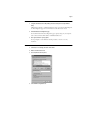
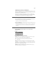
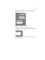
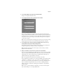
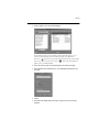
5.
Select “Enable WINS Resolution” and enter the TCP/IP address of the WINS Name Server.
The TCP/IP address of the WINS Name Server is listed on the Configuration Page in the
Network Setup section.
Windows 98
Windows 95
Contact your network administrator if you have difficulty configuring your computer for
WINS.
6.
Click OK, and click OK at the Network dialog box.
You are prompted to restart Windows. Click Yes, and when Windows restarts, continue
with the following procedure.
T O SET UP SMB PRINTING :
1.
Click the Start button, choose Settings, and click Printers.
2.
Click the icon for the printer and choose Properties from the File menu.
3.
Click the Details tab in the Properties window and click Add Port.
A list of connection options is displayed.
4.
In the Add Port dialog box, click Browse to display your network environment.
Page 7
5.
Expand the levels to locate your printer and the print connection (Print, Hold, or Direct) to
which you want to print.
The printer name you are browsing for is the Server Name listed under Network Setup on
the Configuration Page. This name may not be the same as the Server Name listed under
Server Setup on the Configuration Page (which is the name displayed on the Control
Panel).
The network environment and the amount of network traffic determines the amount of
time required for the Browse function.
6.
Select the print connection under the printer and click OK.
7.
In the Add Port dialog box, verify that the network path is correct and click OK.
8.
To confirm the connection, click the General tab in the Properties dialog box.
9.
Click Apply, then click Print Test Page.
10.
The Job Notes window appears. Enter user and job identification information for
accounting purposes, or whatever information is required at your site, and click OK.
If the test page prints successfully, you are ready to print from the computer.
Installing utilities for Windows
The Network screen is no longer displayed when installing Fiery Downloader and Fiery
Spooler. When installing Fiery Downloader, the Install Configuration Screen is not
displayed.
Page 8
Configuring the connection to the RIP Station
The process of configuring the connection to use Fiery Downloader and Fiery Spooler has
changed. Fiery Downloader functions over both IPX/SPX and TCP/IP networks and Fiery
Spooler functions only over IPX/SPX networks.
You should edit the configuration whenever there is any change to your RIP Station or
network, such as a Server Name, IP Address/IPX Address, or device change. First change
the specific RIP Station Setup information before configuring the connection.
B EFORE YOU BEGIN :
•
If you are using IPX/SPX, print the Configuration page from the Control Panel and note
the IPX address and Server Name (in Server Setup) for the RIP Station.
In general, you should use the Ethernet IPX address.
•
If you are using TCP/IP, print the Configuration page from the Control Panel and note the
IP Address of the RIP Station.
You can also set up a Domain Name Server (DNS) for the IP address of the RIP Station
in the HOSTS file and use that name. See your Windows system documentation for
information.
T O CONFIGURE THE F IERY D OWNLOADER CONNECTION :
1.
Launch Fiery Downloader by double-clicking its icon or by choosing it from the
Start>Programs menu.
2.
Click OK.
3.
Enter the appropriate information for the RIP Station.
Nickname—Enter a name for the RIP Station. This name can be any name you wish; it
does not have to match the actual Server Name of the RIP Station.
N OTE : The Nickname cannot contain any of the following seven characters:
[ ] _ " ' <space> <tab>
Protocol—Choose the type of network protocol you are using from the pop-up menu.
Server Name—If you are using the TCP/IP protocol, enter the IP address (or DNS name)
of the RIP Station. If you are using the IPX protocol, enter the actual Server Name of the
RIP Station as it was defined during Server Setup.
IPX Address—(This area is enabled only if you choose IPX from the Protocol pop-up
menu.) Enter the IPX Address of the RIP Station.
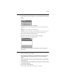
Page 9
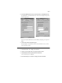
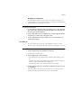
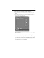
New Device—Enter the name of the device that the RIP Station is connected to: Pro5000.
This device name appears in the Printer Setup section of the Configuration page.
For TCP/IP networks
For IPX/SPX networks
4.
When you have entered all the information, click Add.
5.
With the device name (Pro5000) selected in the Devices list, click OK.
The RIP Station appears in the list of available servers. The first line of the entry displays
the nickname you gave the server, followed by the protocol you chose. The second line
displays the device name.
6.
With the device name (Pro5000) selected in the list of Available Servers, click OK to begin
using the software.
T O MODIFY THE F IERY D OWNLOADER CONFIGURATION :
1.
To edit information for a RIP Station in the list of available servers, select the RIP Station
by its nickname and click Modify. Edit information in the Modify Server Settings dialog box
as necessary, and click OK when finished.
2.
To add a new RIP Station to the list of available servers, click Add. Configure the Add New
Server dialog box as outlined in step 3 through step 5 above.
3.
To remove a RIP Station from the list of available servers, select the RIP Station by its
nickname and click Remove; then click Yes in the Remove dialog box.
Page 10
T O CONFIGURE THE CONNECTION FOR F IERY S POOLER :
1.
Launch Fiery Spooler by double-clicking its icon or by choosing it from the Start\Programs
menu.
2.
Click OK.
3.
Enter the appropriate information for the RIP Station.
Server Name—Enter the Server Name of the RIP Station as it was defined during Server
Setup.
IPX Address—Enter the IPX Address of the RIP Station.
New Device—Enter the name of the device that the RIP Station is connected to: Pro5000.
This device name appears in the Printer Setup section of the Configuration page.
4.
When you have entered all the information, click Add.
5.
With the device name (Pro5000) selected in the Devices list, click OK.
The RIP Station appears in a list of available servers.
6.
With the RIP Station selected in the list of available servers, click OK to begin using
Fiery Spooler.
T O MODIFY THE F IERY S POOLER CONFIGURATION :
1.
In the Chooser dialog box, click Configure.
2.
To edit information for a RIP Station, select the RIP Station by its Server Name and click
Modify. Edit information in the Settings dialog box as necessary, and click OK when
finished.
3.
To add a new RIP Station, click Add. Configure the Settings dialog box as outlined in step 3
through step 5 above.
4.
To remove a RIP Station, select the RIP Station by its Server Name, click Remove, then click
Yes in the Remove dialog box.
5.
Click Close in the Configure dialog box.
The list of available servers reflects the modifications you have made.
Page 11
Installing ColorWise Pro Tools for Windows
Fiery Print Calibrator has been replaced with ColorWise Pro Tools. ColorWise Pro Tools
provides users with greater control of color. Before you begin installation, determine the
following:
• Where do you want to install the utility on your hard disk?
By default, the installer places the utility in the Program Files\Fiery\ColorWise Pro Tools
folder on your hard disk.
• What do you want to name the utility folder in the Windows\Start Menu\Programs
folder?
By default, the installer names the folder “Fiery.”
T O INSTALL C OLOR W ISE P RO T OOLS FOR W INDOWS :
1.
On the User Software CD, open the ColorWise Pro Tools folder.
2.
Double-click the Setup.exe icon.
3.
Follow the instructions in the Setup dialog boxes to complete the installation of ColorWise
Pro Tools.
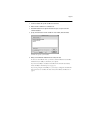
Use the table below as a guide when installing ColorWise Pro Tools. For specific
instructions, read the information in each dialog box.
Name of dialog box:
Action:
When finished:
Welcome
Read the Setup program
introduction.
Click Next.
Software License Agreement
Read the software license agreement.
Click Yes to accept
the terms of the
License Agreement.
Choose Destination Location
Specify a hard disk location for the
installed utility software.
Click Next.
Page 12
Name of dialog box:
Action:
When finished:
Select Program Folder
Specify a folder name for the utility
software located in the Programs
menu.
Click Next.
Setup Complete
Acknowledge that the software
installation is complete.
Click Finish.
See “ColorWise Pro Tools connection for Windows and Mac OS” on page 15 for
information on setting up the ColorWise Pro Tools connection.
Installing the RIP Station ICM printer profiles for Windows
The location and names of ICM profiles have changed slightly since version 1.1 of the User
Software. The ICM folder at the top level of the User Software CD contains nine folders,
each of which contains a file, named “Efme1012.ICM,” that has been created for a specific
media and resolution with the RIP Station. The following table describes which ICM you
should use:
To print on this media:
At this
resolution:
Use the ICM file
in this folder:
Back Light Film
1440 x 720 dpi
P5BLF14
360 dpi Inkjet paper
720 x 360 dpi
P5IJ7
Photo Quality Glossy film
1440 x 720 dpi
P5PGF14
Photo Quality Glossy paper
1440 x 720 dpi
P5PGP14
Photo Quality Glossy paper
720 x 720 dpi
P5PGP7
Photo Quality Inkjet paper
1440 x 720 dpi
P5PIJ14
Photo Quality Inkjet paper
720 x 720 dpi
P5PIJ7
Plain paper
720 x 360 dpi
P5PP7
Transparency
360 x 360 dpi
P5T3
Install these files only if you wish to perform color management on your Windows
computer using compatible applications. If you are using ColorWise Pro Tools (see
page 29) for color management, you do not need to install the files.
Use the following procedure to install the RIP Station ICM printer profiles for Windows
95/98.
N OTE : The ICM printer profiles should not be installed for printing with the Microsoft
Office 97 suite of applications. If you print from Microsoft Office with the ICM profile
installed, JPEG, BMP, and TIFF images print incorrectly.
For information on ICM profiles and color management, see the Color Printing Guide.
Page 13
T O INSTALL THE ICM PROFILES FOR W INDOWS 95/98:
1.
On the User Software CD, open the ICM folder.
2.
Copy the ICM profile from the folder that corresponds to the media and resolution you use
to the Windows\System\Color folder on your hard disk.
3.
In the Windows\System\Color folder, right-click the ICM profile and select Install in Place
(Windows 95) or Install Profile (Windows 98).
When the profile has been correctly installed, its icon appears highlighted in the Color
folder.
In Windows 98, you can assign a selected ICM profile to multiple printers with the
Associate option. This option allows you to associate a profile with your choice of print
devices, eliminating the need to reset the ICM profile each time you print to another
printer on your network.
N OTE : Once a profile has been installed, you should not delete the file without first
uninstalling it. Deleting an installed ICM profile may produce unexpected results.
T O ASSOCIATE THE ICM PROFILE WITH DIFFERENT DEVICES :
1.
Right-click on an ICM profile in the Windows\System\Color folder and select Associate.
2.
In the Associate Device tab of the Profile dialog box, click Add.
The device appears in the Associated Devices section of the tab. Devices added to the list
will be associated with the specific ICM profile until they are removed.
3.
Click OK.
Installing the color reference files
There are two new PANTONE text files for Back Light Film: Fiery Stylus Pro 5000
BLF14.CT, for PANTONE colors on coated media, and Fiery Stylus Pro 5000 BLF14.UT,
for PANTONE colors on uncoated media. Copy these files from the User Software CD to
the location of your choice.
Installing user software on a Mac OS computer
The name of the PostScript Printer description file (PPD) is now “Fiery LX Stylus Pro 5000
v1.3.” A new utility, ColorWise Pro Tools, provides all the functionality of Fiery Print
Calibrator and more.
Installing ColorWise Pro Tools for Mac OS
Fiery Print Calibrator has been replaced with ColorWise Pro Tools. ColorWise Pro Tools
provides users with greater control of color. Before you begin installation, determine where
you want to install ColorWise Pro Tools on your hard disk. By default, the installer places it
in a folder named “ColorWise Pro Tools” on the top level of your hard disk.
Page 14
T O INSTALL C OLOR W ISE P RO T OOLS FOR M AC OS:
1.
On the User Software CD open the ColorWise Pro Tools folder.
2.
Double-click the ColorWise Pro Tools Installer icon.
3.
Read the EFI Software License Agreement and click Accept to accept the terms and
continue installation.
4.
Specify a hard disk location for the ColorWise Pro Tools software, then click Install.
Some files are copied to your hard drive.
5.
When you are notified that installation was successful, click Quit.
In order to use ColorWise Pro Tools, you must have both ColorWise Pro Tools and Mac
OS Runtime for Java (MRJ 2.0) installed on your computer.
If you do not have MRJ 2.0 installed, the ColorWise Pro Tools installer automatically
initiates the MRJ 2.0 installation process (see page 15).
If you are not prompted to install MRJ 2.0, you are ready to configure the ColorWise Pro
Tools connection. See “ColorWise Pro Tools connection for Windows and Mac OS” on
page 15.
Page 15
T O INSTALL MRJ 2.0:
1.
Read the Apple Computer, Inc. Software License and click Agree to install the software.
2.
Click Install.
Some files are installed.
3.
Click Quit.
You are now ready to configure the ColorWise Pro Tools connection to the RIP Station, as
described below.
Installing the color reference files
There are two new PANTONE text files for Back Light Film: P5BLF14C.TXT, for
PANTONE colors on coated media, and P5BLF14U.TXT, for PANTONE colors on
uncoated media. Copy these files from the User CD to the location of your choice.
ColorWise Pro Tools connection for Windows and Mac OS
Before you can start using ColorWise Pro Tools, you must configure the connection to the
RIP Station. Changes to your RIP Station or network may require you to modify the
configuration.
N OTE : Only one user can be connected to ColorWise Pro Tools at a time. You will get an
error message if you try to connect when another user is already using ColorWise Pro Tools.
Configuring the connection
The first time you use ColorWise Pro Tools, you are prompted to configure the connection
to the RIP Station. Windows uses the same configuration for ColorWise Pro Tools and
Fiery Downloader, so any change in configuration affects both utilities.
N OTE : ColorWise Pro Tools functions only over TCP/IP networks.
N OTE : The Windows and Mac OS dialog boxes for configuring the connection to the
RIP Station are almost exactly the same. The dialog boxes that follow show the Windows
interface.
Page 16
B EFORE YOU BEGIN :
Print the Configuration page from the Control Panel and note the IP Address of the
RIP Station.
You can also set up a Domain Name Server (DNS) for the IP address of the RIP Station in
the HOSTS file and use that name. See your Windows system documentation for
information.
T O CONFIGURE THE CONNECTION TO THE RIP S TATION :
1.
Launch ColorWise Pro Tools by double-clicking its icon (Mac OS and Windows) or by
choosing it from the Start>Programs>Fiery menu (Windows).
The Choose Printer Device dialog box appears.
2.
If you have previously configured a Windows connection to the RIP Station, then you are
ready to use ColorWise Pro Tools. See “Using ColorWise Pro Tools” on page 29.
If you have not previously configured a connection, click Add.
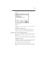
3.
Enter the appropriate information for the RIP Station.
Nickname—Enter a name for the RIP Station. This name can be any name you wish; it
does not have to match the actual Server Name of the RIP Station.
N OTE : The Nickname cannot contain any of the following seven characters:
[ ] _ " ' <space> <tab>
Protocol—Choose the type of network protocol you are using from the pop-up menu.
N OTE : ColorWise Pro Tools software is supported only with TCP/IP, so no choice is
necessary.
Server Name—Enter the IP address (or DNS or hosts name) of the RIP Station.
IPX Address—(This area is not enabled for ColorWise Pro Tools.)
Page 17
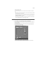
New Device—Enter the name of the device that the RIP Station is connected to: Pro5000.
This device name appears in the Printer Setup section of the Configuration page and it
must be entered exactly the same here.
4.
When you have entered all the information, click Add.
5.
With the device name (Pro5000) selected in the Devices list, click OK.
The RIP Station appears in the list of available servers. The first line of the entry displays
the nickname you gave the server, followed by the protocol. The second line displays the
device name.
6.
With the device name (Pro5000) selected in the list of Available Servers, click Select to
begin using ColorWise Pro Tools.
Page 18
Modifying the configuration
You should edit the configuration whenever there is any change that would affect your
original configuration, such as a change in IP address. First change the specific RIP Station
Setup information before configuring the connection.
T O MODIFY THE CONFIGURATION :
1.
To edit information for a RIP Station in the list of available servers, select the RIP Station
by its nickname and click Modify. Edit information in the Modify Server Settings dialog box
as necessary, and click OK when finished.
2.
To add a new RIP Station to the list of available servers, click Add. Configure the Add New
Server dialog box as outlined in step 3 through step 5 above.
3.
To remove a RIP Station from the list of available servers, select the RIP Station by its
nickname and click Remove.
Fiery WebTools
In order for network users to access and use Fiery WebTools, you need to set certain
RIP Station options in Setup. The names of these options have changed since version 1.1.
T O VERIFY THAT F IERY W EB T OOLS ARE SET UP ON THE RIP S TATION :
1.
Print the Configuration page from the RIP Station Control Panel.
For Instructions see the User Guide.
2.
On the Configuration page, check the following:
• In NetworkSetup>Port Setup>Ethernet Setup, confirm that “Enable Ethernet” is set to
Yes.
• In Network Setup>Protocol Setup>TCP/IP Setup, confirm that TCP/IP is enabled and
that there is a valid, unique IP Address for the RIP Station.
• In Network Setup>Service Setup, confirm that Web Services are enabled.
3.
If all the conditions listed in step 2 are currently set, the RIP Station is properly set up to
use Fiery WebTools.
If any of the conditions listed in step 2 are not currently set, you must change them (as
described in the Administrator Guide) before you can use Fiery WebTools.
Page 19
User Guide
This section of the addendum updates areas of the User Guide. Major changes occurred in
Chapter 5, “Managing Print Jobs,” Chapter 6, “Simulation,” and “Appendix A: Print
Options.”
Managing Print Jobs
Fiery WebTools
Fiery WebTools resides on the RIP Station 5000, but can be accessed over the network
from Windows 95/98, Windows NT 4.0, and Mac OS computers. The RIP Station 5000
has a home page from which remote users can view server functions, manipulate jobs, and
download printer file installers. For specific information on the browsers supported with
Fiery WebTools, see “System requirements” on page 3. All the Fiery WebTools can be
accessed from the RIP Station 5000 home page.
Two new Fiery WebTools have been added:
WebTool:
Summary:
For more information:
WebSetup
(Windows
only)
Allows you to modify the RIP Station
configuration (Setup) remotely. This
function requires the Administrator
password, if one has been set.
See “Using Fiery WebSetup”
on page 46.
Print Monitor
Allows you to check the status of the
printer’s consumables (ink and paper)
from your workstation.
See “Using the Print Monitor”
on page 19.
Using WebSetup
WebSetup is discussed in detail in the Administrator Guide section of this addendum. See
“Using Fiery WebSetup” on page 46 for more information.
Using the Print Monitor
The Print Monitor allows you to check on your printer’s consumables without leaving your
desk.
T O USE THE P RINT M ONITOR :
1.
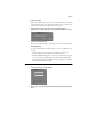
Click the Print Monitor button on the RIP Station homepage.
The Print Monitor dialog box appears.
N OTE : For information on how to access the RIP Station homepage, see Getting Started.
Page 20
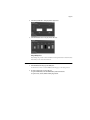
2.
Click the Tray Status tab to check your printer’s paper levels
3.
Click the Ink Status tab to check your printer’s ink levels.
Fiery WebSpooler
Fiery WebSpooler provides a window on RIP Station and printer functions and an interface
from which you can control those functions.
T O L AUNCH F IERY W EB S POOLER :
1.
From the RIP Station home page, click WebSpooler.
For instructions on how to access the RIP Station home page, see the Getting Started.
2.
If a login is required, choose your login level.
To log in as Administrator, enter the Administrator password and click OK.
To log in as Guest, click OK, without entering any password.
Page 21
The Fiery WebSpooler window appears in a new browser window.
Job management features
Unless a password has been defined in RIP Station Setup, you can log in to
Fiery WebSpooler without entering a password, and you are given full privileges which
include:
• A view of current printing jobs and jobs stored on the RIP Station
• Control of printing jobs and a view of the Job Log
• Ability to clear the Job Log
After the Administrator has performed Setup and specified the password, user options
depend on your login level. If you log in to Fiery WebSpooler as Guest, you have the first
option only. If you log in as Administrator, you have all three options. For information
about Setup and specifying passwords, see the Administrator Guide.
You can use Fiery WebSpooler to perform the following functions from your workstation:
• Override current job option settings
• Delete jobs
• Duplicate or rename jobs
• Change the priority of jobs
• Display, print, or delete the Job Log
Most of these functions require the Administrator password. However, even without a
password, you can log in to Fiery WebSpooler as Guest with view-only privileges.
Page 22
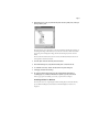
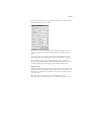
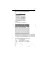
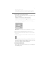
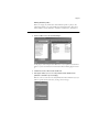
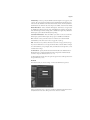
Job List window
Your first view of Fiery WebSpooler is the Job List window, which is divided into three areas
by Spool, RIP, and Print status bars. The Job List window is surrounded by a frame that
includes slider buttons and menus. System information indicators at the bottom of the
window show the availability of hard disk space and RAM on the currently selected
RIP Station.
When the RIP Station is receiving and processing print jobs, the Job List window is a
dynamic display, filled with the names of jobs and their characteristics. Status bars animate
in real time as new jobs are processed and printed, and jobs move to different display areas.
Menu bar
Spool status bar
Spooled jobs
RIP status bar
Rasterized (RIPped) jobs
Print status bar
Printed jobs
System information indicators
The Spool, RIP, and Print areas of the Job List window represent the stages of printing a
job. Jobs come in at the top level (Spool) and drop down to the Print level, unless they are
held along the way.
• Spooled jobs—Jobs listed in the area below the Spool status bar area are PostScript files
stored on the RIP Station disk. These jobs were sent to the Print queue. These PostScript
files are saved on the server’s hard disk. PostScript files can come in packets from the
network, or from another place on the server hard disk. Jobs are added to a queue in the
order in which they arrive, and they generally move to another queue in the same order
unless someone intervenes to change the order.
• RIPped jobs—Jobs listed in the area below the RIP status bar are ready to print. They
have already been rasterized (RIPped, or processed for printing) and are waiting, in order,
for access to the printer. During RIPping, PostScript commands are interpreted in the
RIP Station to allow the printer to print the file the way its originator intended. The
result of this interpretation is a raster file associated with the original PostScript file. In
this raster file (raster image), color data is associated with each dot that can be rendered
by the print engine. The color data tells the print engine whether or not to apply cyan,
magenta, yellow, or black ink to each position on the page.
Page 23
• Printed jobs—Jobs listed in the area below the Print status bar have already been printed.
Printed jobs can be stored on the RIP Station disk. The number of jobs that can be stored
(from 1 to 99) is defined in Setup.
• Errors—Jobs with an error are shown in red. To display the error, double-click the job
line.
If you are logged in as Administrator, you can interact with a job in the window by selecting
it and choosing a command from the Job menu, or by double clicking it and setting print
option overrides. (However, if a password has been set and you are logged in as Guest, you
can only view jobs; you cannot interact with them.)
The job icons displayed in the Fiery WebSpooler window are explained on page 24.
N OTE : If your job does not appear anywhere in the Fiery WebSpooler window, it may have
already been printed; if so, it will appear in the Job Log. To view the Job Log, choose Show
Job Log from the Window menu. (For more information on the Job Log, see page 27.)
Menu bar
The menu bar has four menus. When an action is not available in the current context, the
command is dimmed.
Menu:
File
Job
(For more
information on Job
commands, see
page 26)
Window
Help
Choose this:
Print Job Log
To do this:
Print the Job Log
Delete Job Log
Delete the Job Log
Exit
Log out from the server and exit Fiery WebSpooler
Delete Job(s)
Delete one or more selected jobs
Cancel Printing
Cancel printing for selected job(s)
Cancel RIPping
Cancel RIPping for selected job(s)
Duplicate Job(s)
Duplicate one or more selected PostScript data jobs in the Spool or Print areas
Rename
Rename a selected job
Print
Print the selected job(s)
Process Next
Give top priority to this job
Override Print
Settings
View and edit print settings for the selected job(s); see page 26 for more
information
Show Job List
Show the Job List window
Show Job Log
Show the Job Log window
About
View the Fiery WebSpooler information screen
Page 24
Status bars
Jobs actively involved in the three processes (spooling, rasterizing, and printing) are listed in
the status bars that span the Job List window.
Status bars show the filename and user name for the active process, and an indication of its
progress. Each status bar heads the list of jobs that have completed the process. Thus,
beneath the Spool status bar, you see a list of spooled files; beneath the RIP status bar, you
see a list of rasterized (RIPped) files. Beneath the Print status bar, you see a list of jobs that
have already been printed.
N OTE : In the Spool status bar, the filename and user information always appear as
“Unknown.” This information is not available until the job has finished spooling to the
RIP Station disk.
Job icons
There are two types of icons that are used for active jobs:
Icon:
Active jobs:
(white icons)
PostScript data after printing, raster deleted
PostScript icon
PostScript or raster data headed for printing
Printer icon
Spool area
The job icon in the Spool area is described below:
Spool area icon:
What it indicates:
PostScript data headed for Print
How long you see the job:
Until the RIP is free
White printer icon
The Spool area is the waiting area for jobs that will be RIPped (jobs in the Spool queue).
Print queue jobs Network jobs sent to the Print queue appear in the Spool area where
they are shown with a white printer icon. When they reach the head of the queue, they are
RIPped and printed.
Direct connection jobs Jobs printed to the Direct connection are not displayed in the
Fiery WebSpooler job lists. They are displayed briefly in the status bars (where they cannot
be selected) and are included in the Job Log.
Page 25
RIP area
The job icon in the RIP area is described below:
RIP area icon:
What it indicates:
Raster data headed for Print in its
turn
How long you see the job:
Until printer is free to print the
job
White printer icon
After a job is rasterized, it goes into the RIP area. The RIP area holds only raster data (i.e.,
jobs that have been rasterized). Jobs in the RIP area are waiting for the printer to be free.
N OTE : Raster jobs in the RIP area that are waiting to print cannot be manipulated by job
commands.
Print area
The job icon in the Print area is described below:
Print area icon:
What it indicates:
PostScript data only—raster data
has been deleted
How long you see the job:
Until the job limit is reached
White PS icon
The Print area, also referred to as the Printed queue, contains jobs that have already been
printed.
N OTE : A job row that appears in light red indicates that a PostScript error occurred while
printing the job. To see the error, double-click anywhere in the row.
Newly printed jobs are added to the Printed queue, and are shown at the top of the list. Jobs
are saved in the Printed queue until the job limit is reached. When the first job over the
limit is printed, the oldest job is deleted from the disk. The default job limit is 10 jobs. The
value for Jobs Saved in Printed Queue can be changed in Setup by the administrator.
N OTE : If you reprint a job in the Printed queue, the job returns to its original position in
the Printed queue after it is printed.
While it is printing, a job consists of PostScript and raster data; jobs with only PostScript
data remaining are represented by a white PS icon.
Page 26
Job commands
Using the commands in the Job menu, you can alter the destinations, priorities and other
characteristics of jobs that appear in the Fiery WebSpooler window.
Job commands are used to assign a selected job to a new destination or process. These
commands are available from the Job menu (see page 23). The job commands available at a
given time depend on the context; unavailable commands are dimmed.
The job commands available for selected jobs in the Job List window are listed in the
following table.
Choose this:
To do this:
Delete Job(s)
Delete the job(s)
Cancel Printing
Cancel printing for selected job(s)
Cancel RIPping
Cancel RIPping for selected job(s)
Duplicate Job(s)
Duplicate one or more selected PostScript data jobs in the Spool or
Print areas. You can assign different print options or a different
destination to the duplicate job(s). (The Duplicate command
actually creates a reference to the original job, with the same name.)
Rename
Rename the job (PostScript file)
Print
Print the job in its turn
After printing, keep the printed job in the Print area until the job
limit is reached.
Process Next
Give top priority to this job
RIP (and then print) it as soon as the processor is free, before other
waiting jobs
Option is dimmed if there are no other waiting jobs
Override Print Settings
View and override print settings for a selected job or a group of
selected jobs
Overriding print settings
When logged in as Administrator, you can use the Override Print Settings command to
check and override the print option settings (properties) of all jobs.
You can use this command for several purposes:
• To override a setting based on printed output or other print device conditions
• To change settings for a duplicate of the original job
• To print a single copy of a job before printing the number of copies required by the user
Page 27
To change the print settings for a job, double-click the job line or select the job and choose
Override Print Settings from the Job menu.
The options you set here are the same ones you set from the Print dialog box when you
print from an application. For information about print options, see “Print Options” on
page 42.
If you want to retain a copy of the job with its original settings, duplicate the job and
rename the duplicate before you change any settings (see “Job commands” on page 26).
The Override Print Settings dialog box displays all the job settings encoded by the
PostScript printer driver that can be decoded by the RIP Station. If you (as operator) have
not changed anything, these are the settings a user entered before sending the job.
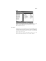
Using the Job Log
From Fiery WebSpooler, you can view and print a log of all jobs printed by the RIP Station,
including jobs downloaded with Fiery Downloader. You can also save the Job Log to a text
file which you can then import into a spreadsheet or word processing application for job
accounting purposes.
N OTE : If you logged in as Administrator, you can delete the Job Log from
Fiery WebSpooler (see page 29). The Job Log is not available if you logged in as Guest.
Page 28
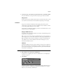
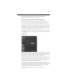
T O DISPLAY , UPDATE , PRINT , DELETE , AND SAVE THE J OB L OG :
1.
Choose Show Job Log from the Fiery WebSpooler Window menu.
2.
Click All or specify a date range.
3.
Click OK.
The Job Log appears in a new browser window.
Update
Print
Delete
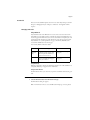
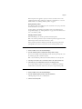
The Job Log displays each job and the following information: status, document name, user
name, date, start time, end time, process time, file size, device, paper size, media, number of
originals, number of color pages, number of black-and-white pages, total number of pages,
Note1, and Note2.
The Status column provides the following information about jobs:
4.
5.
OK
The job was printed normally.
ERROR
An error occurred during processing or printing.
CANCEL
The job was canceled before printing was completed.
To update the Job Log, click the Update button.
To print the Job Log, choose Print Job Log from the File menu or click the Print button.
The information displayed in the Job Log window prints to the current RIP Station. When
you print the Job Log, totals are printed for all appropriate columns.
Page 29
6.
To clear the Job Log, choose Delete Job Log from the File menu or click the Delete button.
The system administrator can also print and clear the Job Log from the Control Panel.
Fiery Spooler
The Fiery Spooler interface and functionality are almost exactly the same as before. See the
User Guide for more information. The Override Print Settings dialog box has changed.
Simulation
The processes of simulation and calibration have changed greatly from the previous
software version as the result of a new utility, ColorWise Pro Tools. In addition, a number
of new DuPont qualified simulations are now available.
For information on installing and configuring a connection to ColorWise Pro Tools, see the
Getting Started section of this addendum.
Using ColorWise Pro Tools
ColorWise Pro Tools, which includes Calibrator, Color Editor, and Profile Manager, allows
for great control of color printing.
N OTE : Only one user can be connected to ColorWise Pro Tools at a time. You will get an
error message if you try to connect when another user is already using ColorWise Pro Tools.
N OTE : ColorWise Pro Tools for Mac OS and Windows computers are fundamentally the
same; differences are noted in this addendum. The windows and dialog boxes you see
illustrated are the Windows version.
Calibrator
Calibrating the RIP Station ensures consistent, reliable color output. You can calibrate the
RIP Station with Calibrator and the EPSON Color Calibrator colorimeter (available as an
option). Using the colorimeter, you can quickly measure color patches and download these
measurements to the RIP Station.
T O CALIBRATE THE P RO 5000 USING C ALIBRATOR :
1.
Start ColorWise Pro Tools and connect to the RIP Station.
For instructions on configuring the connection to the RIP Station, see “Configuring the
connection” on page 15.
2.
Click Calibrator.
EPSON Color Calibrator should appear as the measurement method. This information is
provided to Calibrator by the RIP Station. If EPSON Color Calibrator does not appear,
make sure you are connected to the RIP Station.
Page 30
3.
Under Check Print Settings, choose the desired calibration set.
Choose the appropriate calibration set for the type of media on which you will be printing
most often.
N OTE : It is not necessary to recalibrate before printing on a media type other than the one
you select here.
4.
Under Generate Measurement Page, click Print.
5.
Choose the paper size and input tray to use for the measurements page and click Print.
6.
Use the EPSON Color Calibrator to read the measurements page data into a file.
See your EPSON Color Calibrator documentation for instructions.
7.
Under Get Measurements, click From File and browse to the location of the file you created
with the EPSON Color Calibrator.
8.
Select this file and click Open.
9.
When you are notified that the measurements were read successfully, click OK, then click
Apply to implement the new calibration.
N OTE : Changing the calibration has the potential to affect all jobs for all users, so you may
want to limit the number of people authorized to perform calibration. An Administrator
password can be set to control access to calibration from the RIP Station Control Panel.
Page 31
T O RESTORE DEFAULT CALIBRATION MEASUREMENTS :
1.
Launch ColorWise Pro Tools and click Calibrator.
2.
Click Restore Device.
3.
Click OK to restore the factory default calibration.
N OTE : Restore device applies the factory default calibration measurements to all calibration
sets, not just the currently selected one.
Color Editor
The Color Editor is used to customize simulation profiles and can be accessed either
directly, by clicking on its icon, or indirectly, through the Profile Manager.
Editing Simulations
Color Editor allows you to create custom simulations by editing existing simulations and
saving the changes as a new simulation. With Color Editor, you can fine tune a simulation
on your RIP Station to meet your exact specifications. You select a simulation first, then
you edit it.
Color Editor has two Edit Modes for editing simulations: Master and TRI. Use Master
mode to a create custom master simulation that affects all print jobs to which it is applied,
regardless of which of the 15 Print Mode options (see page 44 for a list) you choose for a
particular job.
Use TRI mode to created custom linked simulations that affect the same print job
differently, depending on which Print Mode you choose for that particular job. If you
choose a Print Mode for which you have created a custom linked simulation, that
simulation is automatically applied to the job. If you choose a Print Mode for which there is
no custom linked simulation, then the master simulation is automatically applied.
Page 32
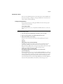
T O EDIT A SIMULATION IN M ASTER MODE :
1.
Open ColorWise Pro Tools and click either Color Editor or Profile Manager.
2.
Choose the simulation you wish to edit and click Select (Color Editor) or Edit (Profile
Manager).
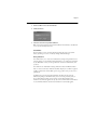
3.
Choose Master from the Edit Mode drop-down menu.
You can use this dialog box to view or edit simulations. The graph allows you to view and
manipulate color output values.
4.
Select the color channels you want to edit by clicking in the white box to the left of the
color.
The eye icon indicates which channels are visible (Cyan and Magenta in the example
below) on the graph and affected by changes to the curve(s) and the brightness and dot gain
controls.
You can view all four channels (Cyan, Magenta, Yellow, and Black) at a time or any
combination of the channels. Working with only one or two channels at a time helps you to
fine-tune your adjustments and to edit curves on a monochrome screen.
N OTE : If all channels are turned on initially, they might overlap and be difficult to
distinguish. To see other channels, move or turn off the topmost channel.
Page 33
5.
You can adjust brightness by using the plus and minus buttons.
Changes to the brightness affect the curve(s).
6.
You can adjust the Dot Gain value by clicking the Dot Gain button.
This is used for simulating press output. You can choose either the North American or
European standard. Then use the sliders to select the desired Dot Gain. The valid values for
North American gain at 50% input are 0%-50% output. The valid values for European at
40% input are 0%-59% gain on output; the valid values for European at 80% input are
0%-20% gain on output.
N OTE : If you use Dot Gain values, all existing points on the curve are removed. A warning
dialog box gives you the chance to cancel Dot Gain settings before they are applied.
7.
You can adjust the curves directly by clicking and dragging points on the curve or by
entering numbers directly into the input and output boxes.
The graph maps input percentage to output percentage. The curve you selected appears,
and points along the curve are marked so that you can adjust them.
N OTE : You should only adjust points in this way after you have entered your desired
Brightness and Dot Gain values.
8.
When you are finished, click Save and enter a name for the new simulation.
This saves your custom simulation to the RIP Station. If you edit one of the press standard
targets (for example, SWOP-COM/M, DIC, or Euroscale), you may want to include the
original name as part of the new target name, for example, DIC-New. This helps you
remember what the new target information is based on.
N OTE : Factory profiles are locked and must be saved under a new name.
Custom simulations must be linked to one of the ten predefined custom simulation names
(“Simulation-1”, “Simulation-2”, and so on) in order to be accessible from the printer
driver. You can create as many custom simulations as you want, but a maximum of ten of
these are available from the printer driver at any one time. See “Defining simulation
profiles” on page 41 for information on linking custom simulations to the predefined
simulation names.
N OTE : If you set a custom simulation as the default, you can access it from the printer
driver without linking it to one of the predefined names.
Page 34
T O EDIT A SIMULATION IN TRI MODE :
1.
Open ColorWise Pro Tools and click either Color Editor or Profile Manager.
2.
Choose the simulation you wish to edit and click Select (Color Editor) or Edit (Profile
Manager).
3.
Choose TRI from the Edit Mode drop-down menu and select the Print Mode option with
which your edited simulation will be linked.
In the example above, the Euroscale simulation is being edited for use with the PQ Inkjet
Paper 720 Print Option.
N OTE : Simulations edited in TRI mode must be linked to a specific Print Mode.
4.
Edit and save the simulation as described in step 4 through step 8 on page 32.
If you select this new simulation for a print job for which the Print Mode option is PQ
Inkjet Paper 720, your TRI simulation is automatically applied. If the Print Mode option is
set to something other than PQ Inkjet Paper 720, then the Master simulation is applied.
N OTE : A custom simulation can consist of a custom master simulation and/or up to 15
custom linked simulations (one for each Print Mode).
Page 35
Undoing simulation edits
You can undo the changes you made to simulations (master and linked) in a number of
ways:
• If you have not yet saved your edits, click Done on the Color Editor menu bar, then click
No when prompted to save the changes
• If you have saved your edits under a new simulation name and want to delete all edits (in
both Master and TRI modes) to the simulation, see “To delete simulation profiles from
the RIP Station hard disk:” on page 40.
• If you have saved your edits under a new simulation name and want to undo the edits to
one or more linked simulation, see the following procedure.
T O UNDO EDITS MADE TO A CUSTOM LINKED SIMULATION :
1.
Open ColorWise Pro Tools and click either Color Editor or Profile Manager.
2.
Choose the simulation for which you wish to undo edits and click Select (Color Editor) or
Edit (Profile Manager).
3.
Choose TRI from the Edit Mode drop-down menu and select the Print Mode option with
which your unwanted edits are linked.
In this case, the custom simulation is linked with the Transparencies 360 Print Mode.
Page 36
4.
Click Revert to Master.
N OTE : Revert to Master makes the curves for one or more linked simulations match the last
saved master simulation. If you have edited and saved changes to a master simulation, your
linked simulations will revert to the changed master, not the original.
5.
Indicate whether you want to revert the currently selected linked simulation
(Transparencies 360 in the example) only, or revert all linked simulations, then click OK.
6.
Click OK at the warning dialog box.
The curves for the linked simulation(s) now match the last saved master simulation exactly.
Testing simulations
You can view a printed sample of a simulation before you save it to your RIP Station. You
can print:
• Comparison Page—This page is provided with ColorWise Pro Tools and shows a
comparison of images and colored patches with and without simulation.
• User defined CALIB.PS in Hold Queue— You can create a custom comparison page and
save it as a PostScript or an Encapsulated PostScript (EPS) file called CALIB.PS. Then
print the file to the Hold Queue of the RIP Station from your application or download it
to the Hold Queue with Fiery Downloader.
T O TEST A SIMULATION :
1.
Click Test Print from the Color Editor window.
2.
Specify a page to print and the paper size and input tray (Comparison Page only) and click
Print.
Page 37
Profile Manager
Profile Manager allows you to manage and edit ICC profiles. In the case of the RIP Station,
this means simulations, accepted industry standards for simulating output of a press. You
can print to the RIP Station and your printed output simulates the range of colors a press
would produce.
N OTE : Changing the RIP Station default simulation affects all jobs for all users, so you
might want to limit the number of people authorized to use ColorWise Pro Tools.
Several simulations are provided with the RIP Station, and you can create additional ones as
needed by modifying the existing ones. You can also download simulations from any
workstation to the RIP Station. The simulations provided are:
• SWOP-COM/M— SWOP Commercial 3M Match Print
• SWOP-COM/F— SWOP Commercial FujiColorArt Print
• Euroscale— European press standard
• DIC— Japanese press standard
• DuPont WaterProof ®(PUB, MAT, COM)— Proofing standard for negative commercial
printing
• DuPont Cromalin® (PUB, MAT, COM)— European proofing standard for offset printing
DuPont Color Proofing
The six DuPont qualified simulations— DuPont WaterProof (PUB, MAT, and COM) and
DuPont Cromalin (PUB, MAT, and COM)— were created by DuPont. These simulations
were designed for precise color output that will match the color of these proofing products.
The DuPont Cromalin COM and DuPont WaterProof COM simulations are only valid
when using the DuPont/EPSON Commercial Proofing Paper. The DuPont Cromalin
MAT and DuPont WaterProof MAT simulations are only valid when using the
DuPont/EPSON Matte Proofing Paper. The DuPont Cromalin PUB and DuPont
WaterProof PUB simulations are only valid when using the DuPont/EPSON Publication
Proofing Paper. The use of any other media invalidates the color fidelity and can produce
unpredictable color results.
Setting the default simulation
The default simulation is applied to all print jobs sent to the RIP Station, unless the user
chooses a per-job simulation. Therefore, the default should be the most commonly used
simulation.
Page 38
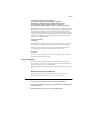
T O CHOOSE A DEFAULT SIMULATION :
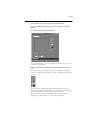
1.
Launch ColorWise Pro Tools and click Profile Manager.
The left-hand side of the screen lists the ICC profiles in the default directory of your
workstation. The right-hand side lists the simulation profiles on the RIP Station.
The lock icon
indicates that these profiles cannot be deleted and can only be edited if
they are saved under a new name. The target icon
indicates the default simulation
profile, in this case SWOP-COM/M.
2.
Click on the profile you want as the default simulation, then click Profile Settings.
3.
In the Simulation Profile Settings dialog box, select CMYK Input under Default for, and
click Apply.
4.
Click OK.
5.
In the main Profile Manager window, the target icon appears next to the new default
simulation.
Page 39
Downloading simulation profiles
The RIP Station comes with ten factory-installed simulation profiles. It is possible to
download additional simulations from any workstation connected to the RIP Station.
T O DOWNLOAD A SIMULATION PROFILE :
1.
Launch ColorWise Pro Tools and click the Profile Manager.
The left-hand side of the main Profile Manager windows lists the ICC profiles in the default
directory of your workstation.
For Windows 95/98, the default directory is \Windows\System\Color
For Windows NT 4.0, the default directory is \Winnt\System32\Color
For Mac OS, the default directory is System Folder:Preferences:ColorSyncTM Profiles if you
have ColorSync 2.0, and System Folder:ColorSyncTM if you have ColorSync 2.5
2.
If the desired profile does not appear, you can browse to a different directory by clicking
Browse.
N OTE : You cannot browse using Mac OS. To access an ICC profile, it must be placed in the
default directory.
3.
Browse to the directory containing the profile you want to download and click OK.
4.
When the profile you wish to download appears in the list in the main Profile Manager
window, select it.
5.
If the profile is compatible with the RIP Station, a green arrow will indicate that the profile
is available for download.
N OTE : All ICC profiles in the selected directory on your workstation are displayed in the
list in the main Profile Manager window. Just because a profile is listed does not mean it can
be downloaded to the RIP Station. Only those profiles with a device class of printer and an
output color space of CMYK are compatible with the RIP Station.
6.
7.
Click the arrow to download the profile.
Click OK when the download is complete.
The new profile now appears on the list of simulation profiles on the right-hand side of the
main Profile Manager window.
Page 40
Before this profile can be applied to a print job, it must be associated with one of the
predefined simulation names (Simulation-1, Simulation-2...Simulation-10) or set as the
default simulation. See “Defining simulation profiles” on page 41.
Editing simulation profiles
The simulation profiles on the RIP Station can be customized to meet your specific needs
and the characteristics of your printer.
Use Color Editor to edit simulations. Color Editor can be accessed either directly or
through Profile Manager. See “Editing Simulations” on page 31 for more information on
how to edit simulation profiles.
Managing simulation profiles
With Profile Manager, you can back up and delete simulation profiles.
N OTE : You can back up and delete only those simulation profiles that appear in the main
Profile manager window without the lock icon next to them.
Back up simulation profiles for safekeeping. You should always back up profiles before
updating RIP Station software to ensure that no custom simulation profiles are lost.
T O BACK UP SIMULATION PROFILES :
1.
2.
Launch ColorWise Pro Tools and click Profile Manager.
Select the simulation profile on the RIP Station that you wish to backup.
The arrow in the middle of the Profile Manager window becomes green and points to the
left, indicating the profile is available for upload.
N OTE : Custom simulation profiles based on DuPont simulations cannot be uploaded.
3.
Click the green arrow, then choose a name and location for the profile and click Save.
4.
Click OK when you are notified that the profile was successfully uploaded.
You can delete simulation profiles to free up disk space on the RIP Station (although
simulation files are small) and to make sure no one uses the wrong simulation profile.
T O DELETE SIMULATION PROFILES FROM THE RIP S TATION HARD DISK :
1.
2.
Launch ColorWise Pro Tools and click Profile Manager.
Select the simulation profile you wish to delete and click Delete.
A Warning dialog box asks you to confirm deletion.
3.
Click Yes to delete the profile.
Page 41
Defining simulation profiles
Before you can apply any downloaded or edited simulation profile to a print job, that
profile must be linked to one of the predefined custom simulation names. There are ten
names available for custom simulations— Simulation-1, Simulation-2,...Simulation-10.
T O DEFINE A SIMULATION PROFILE :
1.
Launch ColorWise Pro Tools and click Profile Manager.
For the purposes of this example, assume DIC-new is a custom profile created with Color
Editor. As you can see, DIC-new has no information under the heading Appear in Driver
as.
2.
Click DIC-new and choose Edit or double-click DIC-new.
3.
Under Appear in Driver as, choose one of the predefined custom simulation names
(Simulation-1...Simulation-10) and click Apply.
Make sure to choose a name that is not already linked with another simulation. If you try to
define two profiles with the same name, you will get an error message.
Page 42
4.
Click OK.
Simulation-1 now appears under the Appear in Driver as heading for DIC-new. Choosing
Simulation-1 from the CMYK Simulation option in the printer driver will apply the
DIC-new simulation to the print job.
Print Options
Print options give you access to the special features of your printer and the RIP Station. You
can specify print options in several places—from the server, from the printing application,
from Fiery Downloader, from Fiery Spooler, and from Fiery WebSpooler. The print options
that have changed are described below and in the table that follows. For information on all
other print options, see the User Guide.
RGB Source Gamma is now called (Other) Gamma. RGB Source Phosphors is now called
(Other) Phosphors. RGB Source White Point is now called (Other) White Point.
Page 43
Override hierarchy
In the following table, the default printer driver settings are underlined. The override
hierarchy is as follows: a user’s printer driver settings override the server’s default settings;
settings made from Fiery Spooler or Fiery WebSpooler override the user’s printer driver
settings; and Fiery Downloader settings override Print dialog box settings.
Print option:
Settings:
(default is underlined)
Description:
Requirements and
constraints:
CMYK
Simulation
DuPont Cromalin COM/
DuPont Cromalin MAT/
DuPont Cromalin PUB/
DuPont WaterProof COM/
Dupont WaterProof MAT/
DuPont WaterProof PUB/
SWOP-COM M/
SWOP-COM F/
Euroscale/DIC/
Simulation-1/Simulation-2/
Simulation-3/Simulation-4/
Simulation-5/Simulation-6/
Simulation-7/Simulation-8/
Simulation-9/Simulation-10/
None
The default is SWOP-COM M
for English-language systems,
and Euroscale for European
systems.
Specifies the press simulation to
use for an individual print job
and does not affect the default
simulation on the RIP Station.
Custom simulations must be
defined before users select
them. For information about
defining custom simulations,
see “Defining simulation
profiles” on page 41.
When using the DuPont
simulations, choose one of the
Print Mode settings for DuPont
Epson or Com Prf Ppr and
choose the appropriate page
size.
Print Mode
Com Prf Ppr 720/
Com Prf Ppr 1440/
DuPont Epson MAT 720/
DuPont Epson MAT 1440/
DuPont Epson PUB 720/
DuPont Epson PUB 1440/
PQ InkJet Paper 720/
PQ InkJet Paper 1440/
PQ Glossy Paper 720/
PQ Glossy Paper 1440/
PQ Glossy Film 1440/
BackLight Film 1440/
InkJet Paper 720/
Plain Paper 720/
Transparencies 360
Specifies the media type and the
resolution at which the printer
prints.
For more information, see
page 44.
Be sure to select the correct
setting on your printer. When
using a media type for which
there is not a corresponding
setting on the printer, choose
Other on the printer.
Rendering Style
Photographic/Presentation/
Color Proofing (Photo)/
Color Proofing (Solid)
Specifies the color rendering
dictionary (CRD) for the job.
For more information about
rendering styles, see page 44.
Page 44
Print Mode
Print mode:
Com Prf Ppr 720
Media:
Commercial Proofing paper
DuPont Matte paper
DuPont Publication paper
Photo Quality InkJet paper
720 x 720
1440 x 720
PQ InkJet Paper 1440
PQ Glossy Paper 720
720 x 720
1440 x 720
DuPont Epson PUB 1440
PQ InkJet Paper 720
720 x 720
1440 x 720
DuPont Epson MAT 1440
DuPont Epson PUB 720
720 x 720
1440 x 720
Com Prf Ppr 1440
DuPont Epson MAT 720
Resolution:
Photo Quality Glossy paper
720 x 720
1440 x 720
PQ Glossy Paper 1440
PQ Glossy Film 1440
Photo Quality Glossy film
1440 x 720
BackLight Film 1440
BackLight Film
1440 x 720
InkJet Paper 720
360 dpi InkJet paper
720 x 360
Plain Paper 720
Plain paper
720 x 360
Transparencies 360
Transparency
360 x 360
Rendering Style
Use this option to select a color rendering dictionary (CRD) to be used when you print
RGB images, objects, and text.
Photographic—optimizes the range of colors on the RIP Station to produce the best
results for photographic or bitmapped images.
Presentation—optimizes the output of pure, saturated colors such as those used in business
presentations.
Color Proofing (Photo)—for CMYK printing provides a close match to the device being
simulated, regardless of the media being used. Also good for printing RGB images.
Color Proofing (Solid)—for CMYK printing provides the closest match to the device
being simulated, including rendering the paper color as the background.
Page 45
Administrator Guide
This section of the addendum updates areas of the Administrator Guide for the RIP Station.
There were some changes to Chapter 2, “Setting up the RIP Station” and a whole section
has been added on using Fiery WebSetup.
Setting up the RIP Station
The only change to the process of setting up the RIP Station is the Color Setup options
available from the Control Panel.
Color Setup options
Color Setup options allow you to set the parameters the RIP Station uses to control color
output.
T O ACCESS C OLOR S ETUP OPTIONS :
1.
In the main Setup menu on the RIP Station Control Panel, choose Color Setup.
2.
Enter the options appropriate to the printing requirements at your site.
3.
When you have finished, save the changes.
In the list of options that follows, default values, where applicable, appear in square
brackets.
RGB Source
EFIRGB/sRGB (PC)/Apple Standard/Off [EFIRGB]
The RGB source is the color space used to control color for conversion from screen to
printed output. EFIRGB is based on the reference points used in the creation of the
RIP Station software. sRGB is based on an average of a large number of PC monitors. Apple
Standard is the standard reference point for Apple’s ColorSync software.
Rendering Style (formerly called Default CRD)
Photographic/Presentation/Color Proofing (Photo)/Color Proofing (Solid)
[Color Proofing (Photo)]
Rendering Style defines how color is converted from RGB and CMYK data to printed output. Photographic, designed for images, retains the relative balance between colors to maintain the overall appearance of the image. Presentation, designed for bright colors, produces
the saturated prints needed for most business presentations. Color Proofing (Photo) and
Color Proofing (Solid) are both good for proofing CMYK print jobs. The main difference is
that Color Proofing (Solid) simulates not only the device, but also the paper color.
Page 46
CMYK Simulation (formerly called Press Simulation)
DuPont Cromalin COM/DuPont Cromalin MAT/DuPont Cromalin PUB/
DuPont WaterProof COM/DuPont WaterProof MAT/DuPont WaterProof PUB/
SWOP-COM M/SWOP-COM F/Euroscale/DIC/Simulation-1...Simulation-10/
None [SWOP-COM M for English-language systems, Euroscale for European systems]
With CMYK simulation, you can simulate commercial presses or other proofing methods
by applying the factory profiles. You can also simulate virtually any CMYK printing device
by downloading and applying that device’s profile. The SWOP standard is used in the
United States, DIC in Japan, and Euroscale in Europe. The DuPont WaterProof® simulations are the proofing standard for negative commercial printing. The DuPont Cromalin®
simulations are the European proofing standard for offset printing. Custom simulation
standards are user defined and named.
Pure Black Text/Graphics
On/Off [On]
The Pure Black Text/Graphics option optimizes black text and line art. The option may
minimize ink use for documents consisting of a mixture of color and black-only pages.
With this option On, black text and line art are printed with black ink only. With the
option Off, black text and line art are printed using all four colors of ink.
Save Changes
Yes/No [Yes]
Select Yes to activate any changes made in Color Setup; select No to return to the main
Setup menu without making any changes.
Using Fiery WebSetup
After you have performed initial Setup (Server, Network, and Printer Setup) from the
Control Panel, you can complete or change most Setup options using Fiery WebSetup via
an Internet or intranet connection to the RIP Station.
N OTE : Fiery WebSetup is available for Windows 95/98 and Windows NT 4.0 computers
only.
RIP Station Setup from Fiery WebSetup
After changing Setup option settings from Fiery WebSetup, you must reboot the
RIP Station before your changes take effect. See page 59 for instructions.
T O ACCESS F IERY W EB S ETUP :
1.
Launch your browser application and enter the IP address of the RIP Station.
2.
If prompted for a Fiery WebTools login level, select Administrator, enter the Administrator
password, and click OK.
3.
When the RIP Station home page appears, click the WebSetup button.
Page 47
4.
Click one of the Setup buttons: Server Setup, Network Setup, or Printer Setup.
Refer to the following sections for more information.
Server Setup
From this window, you can access Server Setup, Password, and Job Log Setup.
Server Setup
Server Name—Enter a name for the RIP Station (up to ten characters long). This is also the
server name you should enter when you configure the connection to the server over
IPX/SPX. (See Getting Started.) Each time you change the Server Name, you will need to
modify the connection on other workstations that are using the Fiery utilities.
N OTE : Do not use the device name (Pro5000) as the server name. Also, if you have multiple
RIP Station servers and give them the same name, a unique number is appended to the
name that appears in the list of available servers. Although this routes jobs correctly, it may
be inconvenient to users and is not a recommended practice.
Page 48
Print Start Page—Select to specify that the RIP Station should print a start page every time
it restarts. The start page displays information about the RIP Station including the server
name, current date and time, Color Mode, Printer Mode, amount of memory installed in
the RIP Station, last calibration date, network protocols enabled, and connections enabled.
Enable Printed Queue—Select to enable the Printed queue, which creates a storage location
on the RIP Station disk for recent jobs. Users with Administrator privileges can print jobs
from the Printed queue without sending them to the RIP Station again. If you disable the
Printed queue, jobs are deleted immediately after printing.
Jobs Saved in Printed Queue—Enter the number of jobs (from 1 to 99) to be saved in the
Printed queue. Jobs in the Printed queue take up space on the RIP Station hard disk.
Time—Enter the correct system time, based on a 24-hour clock, in the form HH:MM
(Hours:Minutes). The time is used on the cover page and on Job Logs.
Date—Enter the correct system date. The date is used on the cover page and on Job Logs.
If you enter a number that is out of range in either the Time or the Date field, for example,
17 in the month field, you are prompted, when you dismiss the Server Setup menu, to enter
a number that is in range.
Use Character Set—Specify whether the Control Panel should use the Macintosh, DOS, or
Windows character set for displaying filenames. This is important if a filename includes
accented or composite characters (such as é, ü, or æ).
For mixed-platform networks, select the option that gives the best overall representation of
the special characters you use.
Passwords
In the Password tab, you can enter, change, or remove the Administrator password.
If the password already exists, it appears as asterisks in both the Enter New Password and
Verify New Password text boxes. If no password exists, the boxes are blank.
Page 49
TO SET , CHANGE , OR REMOVE PASSWORDS :
1.
To enter a new password, type the password in the Enter New Password field.
Passwords can be any combination of up to 19 characters.
2.
When prompted, enter the new password in the Verify New Password field.
The new password remains in effect until you change it. If a password already exists, the
new entry replaces it. To remove a password, simply select and delete its asterisks.
You can also set or change the Administrator password with Setup from the Control Panel.
N OTE : By default, no passwords are set on the RIP Station. If you do not set passwords, all
users will have access to important functions such as Setup (including setting passwords)
and clearing the server. It is strongly recommended that you set an Administrator password to
protect the server from accidental or incorrect changes to Setup.
If you forget the Administrator password, contact your authorized service representative to
reinstall RIP Station system software. This will clear the Administrator password and allow
you to set a new one.
Job Log Setup
Auto Print Job Log every 55 Jobs—Specify whether you want the RIP Station to print the
Job Log after every 55 jobs. The Job Log displays a list of the last 55 jobs processed on the
RIP Station, with accounting information about each one, including user name, document
name, time and date printed, number of pages, and other job information.
Auto Clear Job Log every 55 Jobs—Specify whether you want to clear the RIP Station Job
Log after every 55 jobs. If you do not turn on this option, the RIP Station saves a file containing a record of all jobs ever printed. Since this file takes up space on the RIP Station
hard disk, clearing the Job Log frees up additional disk space.
You can clear the Job Log manually at any time from Fiery WebSpooler or Fiery Spooler (by
selecting Delete Job Log from the File menu). The Job Log is also cleared when you execute
the Clear Server command, when you choose Clear Server from the main Setup menu, or
when system software is installed or reinstalled on the RIP Station.
Job Log Page Size—Select the size of paper you want to print the Job Log on.
Page 50
Network Setup
You can modify most of the Network Setup options— including Port Setup, Protocol
Setup, PServer Setup, and Service Setup— from Fiery WebSetup.
T O CONFIGURE P ORT S ETUP :
•
Click the Port Setup tab in the Network Setup dialog box.
You can then adjust settings as detailed in the following sections.
Port Setup (Ethernet)
Enable Ethernet—Select if the RIP Station is to be connected to an Ethernet network.
Transmission Speed—Select Auto Detect if your network environment is mixed, or select
the speed (10 Mbps or 100 Mbps) of the network to which the RIP Station is attached.
The options 10 Mbps TP and 10 Mbps AUI refer to how the Ethernet cable is connected,
either through twisted pair cable or the AUI.
Port Setup (Parallel Port)
Enable Parallel Port—Select if you want to print through the parallel port. You can connect
a single Windows computer to the parallel port and print directly to the RIP Station.
N OTE : Enabling the parallel port does not conflict with using Ethernet communication with
the RIP Station.
Ignore EOF Character—Available only if Enable Parallel Port is selected, this option specifies
that the RIP Station should ignore end-of-file (EOF) messages. Check this box to print
PostScript files in binary format (not ASCII); under normal circumstances, the box should
not be checked. When this option is selected, the RIP Station uses the parallel port timeout
value to determine when the end of the file has been reached.
Parallel Port Timeout (seconds)—Available only if Enable Parallel Port is selected, this set-
ting determines how long the RIP Station waits without receiving data from the parallel
port before deciding that the current job is complete. Until the timeout, the RIP Station
cannot receive new jobs through the parallel port, but it can continue to receive network
print jobs.
Page 51
Port Setup (Token Ring)
A Token Ring option is not available for the RIP Station. Therefore, these Setup options
cannot be selected.
T O CONFIGURE P ROTOCOL S ETUP :
•
Click the Protocol Setup tab in the Network Setup window.
The RIP Station can accept jobs via TCP/IP (over Ethernet only), AppleTalk, and IPX/SPX
simultaneously. To configure the RIP Station, choose each protocol and enter the settings
for that protocol.
Protocol Setup (TCP/IP)
Enable on Ethernet—Click to enable if you have a TCP/IP network connected to the
RIP Station over Ethernet cabling.
You must enable TCP/IP for Ethernet to use Fiery WebTools over Ethernet. If you are
using TCP/IP for printing from Windows NT 4.0 workstations, enabling TCP/IP here also
enables you to use Fiery utilities from Windows NT 4.0 workstations using TCP/IP protocols.
IP Address (Ethernet)—Enter the RIP Station IP address for Ethernet. You must change
the default 127.0.0.1 to a valid address for your network. For information about setting up
printing with TCP/IP, see Chapter 3 in the Administrator Guide.
Subnet Mask (Ethernet)—If you need to set the subnet mask, enter one of the following
values:
• 255.0.0.0 if the IP address starts with a number less than 128
• 255.255.0.0 if the IP address starts with a number from 128 through 191
• 255.255.255.0 if the IP address starts with a number greater than 191
N OTE : Be sure to confirm the subnet mask setting with your network administrator before
proceeding. In some cases, the required setting may be different from those listed.
Page 52
Gateway—If your TCP/IP network has a gateway, and users outside the gateway print to
the RIP Station using TCP/IP, enter the gateway address here. Obtain the correct gateway
address from your network administrator.
Protocol Setup (AppleTalk)
Enable AppleTalk—Select to enable Apple Talk if you have an AppleTalk network con-
nected to the RIP Station. This setting enables the RIP Station to communicate over
AppleTalk networks.
Select Zone—The RIP Station searches the network for AppleTalk zones in your network
segment. Scroll through the list to select the AppleTalk zone in which you want the
RIP Station to appear. If your segment has only one zone, the RIP Station is assigned to
that zone automatically.
If no AppleTalk zone can be found, your network may have no defined zones, or else the
network cable has not been connected (see Chapter 4 in the Administrator Guide).
Protocol Setup (IPX Frames)
Select Frames—Click the Select Frames button to specify IPX frames used with NetWare.
See your network administrator to verify which frame type to choose.
In the IPX Frames dialog box, select frames and use the Add and Remove buttons to specify
the selected frames, then click OK.
Page 53
T O CONFIGURE PS ERVER S ETUP :
•
Click the PServer Setup tab in the Network Setup window.
You can modify both NetWare 3.x (Bindery) and NetWare 4.x (NDS) configurations from
Fiery WebSetup. Turn on the Enable NDS option if your network uses NetWare 4.x in
native mode. Click Bindery Setup if your network uses NetWare 3.x or uses NetWare 4.x in
bindery emulation mode.
N OTE : If your network uses both NDS and Bindery, set up NDS first. Setting up NDS after
Bindery will overwrite Bindery Setup. If your network uses both NDS and Bindery, including using NetWare 4.x servers in bindery emulation, the RIP Station cannot service NDS
and bindery emulation servers on the same NDS tree.
PServer Setup (NetWare Services)
The Enable PServer option must be turned on if you have a Novell server connected. You
can, however, change the PServer polling interval and then modify either Bindery Setup or
NDS Configuration.
PServer Setup (NDS Configuration)
In initial setup, the RIP Station was connected to the network and an NDS directory tree,
with a Printer, a Print Server, and one or more Print Queue objects for RIP Station jobs (see
Chapter 3 in the Administrator Guide), was configured. You can make any changes to that
setup through Fiery WebSetup. To modify NDS Setup you may need permission to browse
the NDS tree. If access to the Print Server is restricted, you’ll need a login password.
Note that the terms NetWare server, Novell server, and IPX server are in common use and
are used here interchangeably to mean the server on an IPX network running Novell
NetWare networking software.
Enable NDS
Check this box to enable NDS. Uncheck this box only to remove
NDS support.
Change Trees...
Click to open the Add NDS Tree window. This option is available
only when Enable NDS is selected.
Page 54
Add NDS Tree
You can have only one NDS tree, so the following process is
required to change trees:
1.
2.
Select the current NDS tree and click Remove.
Select the new NDS tree and click Add.
Your new NDS tree selection automatically overwrites
any previous tree selection. If you change the NDS tree
selection and there are also current Bindery settings, you
are alerted that they will be deleted. If you continue with
NDS Setup, you can replace Bindery settings afterwards.
To exit NDS Setup, choose Cancel.
3.
Click OK.
The Select login user window appears.
Select Login
User
1.
Select the User Login object from the display in the Select
Login User window.
2.
Enter a password if necessary.
3.
Click OK.
The Select print server window appears.
Select Print
Server
1.
Select the print server from the display in the Select Print
Server window.
2.
Enter a password if necessary.
3.
Click OK.
The Select print queue root window appears.
Select Print
Queue Root
1.
Select the print queue root from the display in the Select
Print Queue Root window.
2.
Enter a password if necessary.
3.
Click Finish.
The NetWare Setup window reappears, showing the new
settings.
Enter Print
Server
Password
1.
Enter the Print Server password if necessary.
2.
Choose OK.
PServer Setup (Bindery Setup)
Use Bindery Setup if you have already configured one or more bindery servers (file servers
running NetWare 3.x or NetWare 4.x in bindery emulation) with a Print Server and a Print
Queue for RIP Station jobs (see Chapter 3 in the Administrator Guide). Before entering
bindery settings, be sure the RIP Station is connected to the network and the NetWare file
server is running. You’ll need a login name, and, if access to the file server or print server is
restricted, you’ll need a login password.
N OTE : The terms NetWare server, Novell server, and IPX file server are in common use and
are used here interchangeably to mean the server on an IPX network running Novell NetWare networking software.
Page 55
Because you can set up more than one Novell server to handle RIP Station print jobs,
Bindery Setup allows you to add or delete new file server connections and view the
connections you have selected. The options are:
Bindery Setup...
Click the Bindery Setup button to bring up the Add Connections Window.
Add Connections
1.
Click the server you want to add.
2.
Click Add.
3.
Enter your user name and password.
4.
Click OK.
The Add Server password window appears.
5.
6.
Enter your name and password.
Click OK.
The Add Server window shows a list of print servers you can add.
Add Server
1.
Select a print server from the list on the left.
2.
Enter a password if a password is required.
3.
Click Finish.
You return to the main Novell Setup dialog box.
4.
Click OK.
T O CONFIGURE S ERVICE S ETUP :
•
Click the Service Setup tab in the Network Setup window.
Service Setup provides the following:
• Windows Printing Service enables the Microsoft SMB protocol, which supports peer to
peer printing, also known as Windows or SMB printing.
• LPD Printing Service enables lpd printing on TCP/IP networks.
• Web Services enables the http protocol and, therefore, use of Fiery WebTools.
Page 56
Service Setup (Windows Printing Service)
For setting up the Windows printing service, these characters are allowed in the text fields:
uppercase letters, numerals, space, and the following characters:
-_.~!@#$%^&(){}\',
N OTE : Lowercase letters are not allowed, except in the Comment field.
Enable Windows Printing Service—Select to enable SMB (Server Message Block), the file
and printer sharing protocol built into Windows. Enabling SMB allows the RIP Station to
be listed on the network so that Windows clients can print to a particular print connection
(Hold, Print, or Direct) on the RIP Station without any other networking software. For
information on how to set up a Windows client for Windows printing, see “Completing
the SMB printing connection for Windows 95/98” on page 4.
N OTE : Windows (SMB) printing runs over TCP/IP, so TCP/IP must be configured on the
RIP Station and on all workstations that use Windows printing.
Server Name—The server name is the name that will appear on the network. It can, but
does not have to, be the same name as the server name assigned in Server Setup (see Chapter 2 in the Administrator Guide and page 47 of this addendum).
Comment—Server comments (optional) can contain information about the printer. Lowercase letters are allowed in this field.
Domain or Workgroup—Enter the workgroup or domain in which you want the
RIP Station to appear.
Use WINS Server—Select to use a WINS name server. Broadcasts from SMB devices cannot
be routed beyond their original network segment without a WINS name server. Setting up
the WINS name server is outside the scope of this manual. To find out if a name server is
available, contact your network administrator.
IP Address—Enter the IP address of the WINS Server.
Service Setup (Enable Services)
Enable LPD Printing Service—Select to allow lpd printing. See Chapter 3 in the Administrator Guide for more information.
Enable Web Services—Select to enable if TCP/IP is enabled on the RIP Station and on user
workstations, and you wish to make Fiery WebTools available to users (see Chapter 3 in
the Administrator Guide). Fiery WebTools include WebSpooler, Status, WebLink, WebSetup, Print Monitor, and Installer. A Java-enabled Web browser and a valid IP address are
required for each user. See page 3 for details on supported browsers and workstation
requirements.
Page 57
Printer Setup
From this window, you can access two tabs: Printer Setup, and Color and Paper Setup.
T O SET PRINTER OPTIONS :
•
Click the Printer Setup tab.
Printer Setup
Select Printer—Specify the device name of the printer whose connections and protocols
you want to configure.
Printer Type—Specify the model of the printer connected to the RIP Station.
Publish Direct Connection—Select to enable users to print (or download) jobs to the
RIP Station without spooling. When the Direct connection is published, users can print
jobs to the Direct connection and download and delete printer fonts. Jobs printed to the
Direct connection are not available to be reprinted from the Printed queue.
N OTE : The Direct connection must be published to download fonts.
Publish Hold Queue—Select to enable users to print jobs to the Hold queue. Jobs printed to
the Hold queue are not processed until the administrator releases them for printing from
Fiery Spooler or WebSpooler. To enable Fiery utilities, you must publish the Hold queue,
regardless of whether users send jobs to the Hold queue.
Publish Print Queue—Select to enable users to print jobs to the Print queue. Jobs printed to
the Print queue are spooled on the RIP Station disk.
Parallel Connection—This option is available only if the parallel port has been enabled and
you have published one or more print connections (Print queue, Hold queue, or Direct
connection). This setting determines where jobs printed to the parallel port are sent. If only
one queue has been published, parallel port jobs are automatically printed to that print connection.
Page 58
T O SET C OLOR AND P APER S ETUP OPTIONS :
•
Click the Color and Paper Setup tab in the Printer Setup window.
Color and Paper Setup
Color Mode—Specifies the default color mode to be used: Color or Grayscale. Before performing calibration on the RIP Station, select Color as the Color Mode.
Default Paper Sizes—Specify whether to print on US paper sizes (for example, letter, legal,
tabloid), or Metric paper sizes (for example, A4, B4, A3) by default. When no page size is
defined within a PostScript file, jobs are printed on letter paper if you select US, or A4 paper
if you select Metric.
Allow Courier Substitution—Specify whether to substitute Courier for unavailable fonts. If
this option is set to No, jobs with fonts that are not available on the RIP Station hard disk
will not print due to a PostScript error.
Print to PS Error—Specify whether the RIP Station should print the available portion of a
print job when it encounters a PostScript error. Select Yes to print the portion of the job
that was processed before the error occurred; select No to cancel the job entirely whenever a
PostScript error is encountered.
RGB Source—The RGB source is the color space used to control color for conversion from
screen to printed output. EFIRGB, which is the default, is based on the reference points used
in the creation of the RIP Station software; sRGB (PC) is based on an average of a large number of PC monitors; and Apple Standard is the standard reference point for Apple’s ColorSync software.
Pure Black Text/Graphics—Select On to print black text and graphics as one color black,
using 100% black ink only. Select Off to print black text and graphics using all four colors
of ink.
Page 59
Restarting the RIP Station
You need to reboot the RIP Station before your changes to Setup take effect.
T O RESTART THE RIP S TATION :
1.
Make sure the information screen on the Control Panel reads Idle.
If Printing or RIPping appears, the RIP Station is processing and you must wait until the
system finishes and reaches the Idle state.
If the RIP Station has just finished processing, wait five seconds after Idle appears before
shutting down.
2.
Click the Reboot Server button.
Color Printing Guide
This section of the addendum updates areas of the Color Printing Guide for the RIP Station.
Changes took place in Chapter 2 “Color Management.”
Color Management
The “Color Management” chapter provided information on how to control and manage
color output with the objective of achieving predictable color results. ColorWise Pro Tools
provides a new way to meet this goal. See “Using ColorWise Pro Tools” on page 29.
RIP Station color management
As discussed elsewhere in this addendum, some of the RIP Station color management
options have changed for version 1.3 of the software.
RIP Station color print options and settings:
What it does
Rendering Style
Photographic/Presentation/Color Proofing (Photo)/
Color Proofing (Solid)
(Default set at Setup)
Applies a RIP Station color rendering style (CRD) to RGB data (see
below). This setting is also applied to CMYK data when a CMYK
Simulation setting other than None is specified (see page 60).
CMYK Simulation
SWOP-COM M/SWOP-COM F/Euroscale/
DIC/DuPont WaterProof PUB/
DuPont WaterProof MAT/DuPont WaterProof COM/
DuPont Cromalin PUB/DuPont Cromalin MAT/
DuPont Cromalin COM/
Simulation-1 through Simulation-10/None
(Default set at Setup)
Adjusts CMYK color data to simulate an offset press standard or a
custom color gamut defined at your site. Choosing None bypasses
simulation (see page 60). If you choose any setting other than None,
specify one of the Color Proofing rendering styles.
Page 60
Rendering styles
The Rendering Style option is used to specify a CRD for color conversions. The following
table describes the various color rendering styles (CRDs) provided with RIP Station
software and provides guidelines on when to use each one. Each color rendering style uses a
different gamut mapping method designed for a particular kind of color usage.
RIP Station rendering style:
Best used for:
Equivalent
ICC rendering style:
Photographic—Preserves tonal relationships in images
rather than exact colors. This rendering style maps out-ofgamut RGB colors to printable colors in a way that retains
differences in lightness. Color accuracy is sacrificed slightly
in favor of presenting color relationships in the way the
human eye perceives them. Photographic rendering
typically gives less saturated output when printing out-ofgamut RGB colors than Solid Color rendering does.
Continuous tone photographs,
including scans and images from
stock photography CDs
Image and Contrast and
Perceptual
Presentation—Creates bright saturated colors. This
rendering style does not try to match printed colors
precisely to displayed colors but instead provides vibrant,
dense colors. Photographic images, however, are treated the
same way as by the Photographic rendering style.
Artwork and graphs in presentations
and continuous tone photographs
Saturation and Graphics
Color Proofing (Photo)— Provides a close match to the
CMYK device being simulated, regardless of the media
being used.
Prepress proofing when a background
color is not desired.
Relative Colorimetric
Color Proofing (Solid)— Provides the closest match to the
CMYK device being simulated, including rendering the
paper color as the background.
The most accurate prepress proofing.
Absolute Colorimetric
CMYK Simulation
The CMYK Simulation print option allows you to print press proofs or simulations. This
option affects CMYK data only.
The CMYK Simulation setting specifies the offset press standard or other color gamut that
you want to simulate. You can also create up to ten custom simulations using ColorWise
Pro Tools (see “Using ColorWise Pro Tools” on page 29).
The CMYK Simulation setting you should specify depends on the press standard for which
the CMYK data was separated. For example, for images that were separated for DIC,
choose DIC as the CMYK Simulation setting. For images that were separated using a
custom separation (such as a device-specific separation or a separation produced with an
ICC-profile), choose None as the CMYK Simulation setting.
The CMYK Simulation setting also determines whether or not CMYK data is affected by
the Rendering Style setting (see page 60).
• With a CMYK Simulation other than None, choose one of the Color Proofing
Rendering Styles.
• With None as the CMYK Simulation, the CMYK data is converted to device-ready color
data using a default PostScript conversion scheme.