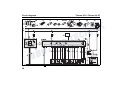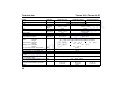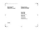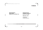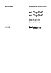
1
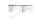
Wasserheizgeräte
Water Heaters
Chauffages à eau
Einbauanweisung
Installation Instructions
Instructions de montage
Thermo 90 S
Thermo 90 ST
Thermo 90 S
Thermo 90 S
Thermo 90 S-ADR
05/2008
1301494C
(Benzin) (Petrol) (Essence)
(Diesel) (Gas-oil)
(Gefahrguttransport)
(Transport of hazardous goods)
(Transport de marchandises dangereuses)
Thermo 90 ST
(Benzin) (Petrol) (Essence)
Thermo 90 ST
(Diesel) (Gas-oil)
Thermo 90 ST-ADR (Gefahrguttransport)
(Transport of hazardous goods)
(Transport de marchandises dangereuses)
Das unsachgemäße Einbauen oder Reparieren von Webasto Heiz- und Kühlsystemen kann Feuer
verursachen oder zum Austritt von tödlichem Kohlenmonoxid führen. Dadurch können schwere oder
tödliche Verletzungen hervorgerufen werden.
Für den Einbau und die Reparatur von Webasto Heiz- und Kühlsystemen bedarf es eines
Webastotrainings, technischer Dokumentation, Spezialwerkzeuge und einer Spezialausrüstung.
Versuchen Sie NIEMALS, Webasto Heiz- oder Kühlsysteme einzubauen oder zu reparieren, wenn Sie
das Webastotraining nicht erfolgreich abgeschlossen und dabei die notwendigen technischen
Fähigkeiten erworben haben und die für einen sachgerechten Einbau und Reparatur nötigen
technischen Dokumentationen, Werkzeuge und Ausrüstungen nicht zur Verfügung stehen.
Befolgen Sie IMMER alle Webasto Einbau- und Reparaturanleitungen, und beachten Sie alle
Warnhinweise.
Webasto übernimmt keine Haftung für Mängel und Schäden, die auf einen Einbau durch ungeschultes
Personal zurückzuführen sind.
Improper installation or repair of Webasto heating and cooling systems can cause fire or the leakage of
deadly carbon monoxide leading to serious injury or death.
To install and repair Webasto heating and cooling systems you need to have completed a Webasto
training course and have the appropriate technical documentation, special tools and special equipment.
NEVER try to install or repair Webasto heating or cooling systems if you have not completed a Webasto
training course, you do not have the necessary technical skills and you do not have the technical
documentation, tools and equipment available to ensure that you can complete the installation and
repair work properly.
ALWAYS carefully follow Webasto installation and repair instructions and heed all WARNINGS.
Webasto rejects any liability for problems and damage caused by the system being installed by
untrained personnel.
La réparation ou l’installation impropre des systèmes de chauffage et de refroidissement Webasto peut
conduire à l’incendie de l’appareil ou encore à des fuites mortelles de monoxyde de carbone pouvant
entraîner de graves lésions voire même la mort.
Pou l’installation ou la réparation des systèmes de chauffage ou de refroidissement Webasto, il est nécessaire d’avoir une formation Webasto, une documentation technique, des outils spécifique et des
équipements particuliers.
N’essayez JAMAIS d’installer ou de réparer un système de chauffage ou de refroidissement Webasto
si vous n’avez pas suivi avec succès la formation Webasto et obtenu ainsi les capacités techniques indispensables et si vous ne disposez pas de la documentation technique, des outils et des équipements
nécessaires à une installation ou à une réparation dans les règles de l’art.
TOUJOURS suivre scrupuleusement les instructions Webasto relatives à l’installation et à la réparation
des appareils et tenir compte de toutes les MISES EN GARDE.
Webasto décline toute responsabilité en cas de problème ou de dommage causé par un système ayant
été installé par du personnel non qualifié.
Thermo 90 S / Thermo 90 ST
Inhaltsverzeichnis
Table of contents
1
2
3
4
5
6
7
8
9
10
11
12
13
1
2
3
4
5
6
7
8
9
10
11
12
13
Gesetzliche Bestimmungen für den Einbau ´ . . . . . . . . . . . 1
Verwendung / Ausführung . . . . . . . . . . . . . . . . . . . . . . . . . . 4
Einbau . . . . . . . . . . . . . . . . . . . . . . . . . . . . . . . . . . . . . . . . . . 5
Einbaubeispiele . . . . . . . . . . . . . . . . . . . . . . . . . . . . . . . . . . . 6
Anschluss an das Kühlsystem des Fahrzeuges . . . . . . . . 7
Brennstoffversorgung . . . . . . . . . . . . . . . . . . . . . . . . . . . . . 8
Brennluftversorgung . . . . . . . . . . . . . . . . . . . . . . . . . . . . . . 13
Abgasleitung . . . . . . . . . . . . . . . . . . . . . . . . . . . . . . . . . . . . 14
Elektrische Anschlüsse . . . . . . . . . . . . . . . . . . . . . . . . . . . 15
Schaltpläne . . . . . . . . . . . . . . . . . . . . . . . . . . . . . . . . . . . . . 17
Erstinbetriebnahme . . . . . . . . . . . . . . . . . . . . . . . . . . . . . . . 28
Störungen . . . . . . . . . . . . . . . . . . . . . . . . . . . . . . . . . . . . . . 29
Technische Daten . . . . . . . . . . . . . . . . . . . . . . . . . . . . . . . . 31
Statutory regulations governing installation . . . . . . . . . .
Use / version . . . . . . . . . . . . . . . . . . . . . . . . . . . . . . . . . . . .
Installation . . . . . . . . . . . . . . . . . . . . . . . . . . . . . . . . . . . . . .
Examples for installation . . . . . . . . . . . . . . . . . . . . . . . . . .
Connection to the vehicle cooling system . . . . . . . . . . . .
Fuel supply . . . . . . . . . . . . . . . . . . . . . . . . . . . . . . . . . . . . .
Combustion air supply . . . . . . . . . . . . . . . . . . . . . . . . . . . .
Exhaust pipe . . . . . . . . . . . . . . . . . . . . . . . . . . . . . . . . . . . .
Electrical connections . . . . . . . . . . . . . . . . . . . . . . . . . . . .
Circuit diagrams . . . . . . . . . . . . . . . . . . . . . . . . . . . . . . . . .
Initial start-up . . . . . . . . . . . . . . . . . . . . . . . . . . . . . . . . . . .
Troubleshooting . . . . . . . . . . . . . . . . . . . . . . . . . . . . . . . . .
Technical data . . . . . . . . . . . . . . . . . . . . . . . . . . . . . . . . . . .
35
38
39
40
41
42
47
48
49
51
62
63
65
I
Thermo 90 S / Thermo 90 ST
1
Statutory regulations governing installation
Statutory regulations governing installation
1.1. Statutory regulations governing installation
The Thermo 90 S / Thermo 90 ST heater has been type-tested and
approved in accordance with EC Directives 72/245/EEC (EMC), 2001/
56/EC (heater) and ECE R122 with the following EC permit numbers:
e1*2001/56*2004/78*0005*-e1*72/245*95/54*1173*-e1*2001/56*2004/78*0019*-E1 R122 00 0217
Primarily the regulations of Annex VII of the Directive 2001/56/EG and
Part 2 or Annex 7 of the directive ECE R122 must be observed for the
installation.
NOTE:
The provisions of these Directives are binding within the territory
governed by EU Directive 70/156/EEC and should similarly be
observed in countries without specific regulations.
IMPORTANT
Failure to follow the installation instructions and the notes contained
therein will lead to all liability being refused by Webasto. The same
applies if repairs are carried out incorrectly or with the use of parts other
than genuine spare parts. This will result in the invalidation of the type
approval for the heater and therefore of its homologation / EC type
licence.
(Extract from Directive 2001/56/EC Annex VII)
1.7.1. A clearly visible tell-tale in the operator's field of view shall inform
when the combustion heater is switched on or off.
2. Vehicle installation requirements
2.1. Scope
2.1.1.Subject to paragraph 2.1.2, combustion heaters shall be installed
according to the requirements of this Annex.
2.1.2.Vehicles of category O (trailers) having liquid fuel heaters are
deemed to comply with the requirements of this Annex.
2.2. Positioning of heater
2.2.1. Body sections and any other components in the vicinity of the
heater must be protected from excessive heat and the possibility of fuel
or oil contamination.
2.2.2. The combustion heater shall not constitute a risk of fire, even in
the case of overheating. This requirement shall be deemed to be fulfilled
if the installation ensures an adequate distance to all parts and suitable
ventilation, by the use of fire resistant materials or by the use of heat
shields.
2.2.3. In the case of M2 and M3 vehicles, the heater must not be
positioned in the passenger compartment. However, an installation in an
effectively sealed envelope which also complies with the conditions in
paragraph 2.2.2 may be used.
2.2.4. The label referred to in paragraph 1.4 (model plate), or a duplicate
(duplicate model plate), must be positioned so that it can be easily read
when the heater is installed in the vehicle.
35
Statutory regulations governing installation
2.2.5 Every reasonable precaution should be taken in positioning the
heater to minimise the risk of injury and damage to personal property.
2.3. Fuel supply
2.3.1. The fuel filler must not be situated in the passenger compartment
and must be provided with an effective cap to prevent fuel spillage.
2.3.2. In the case of liquid fuel heaters, where a supply separate to that
of the vehicle is provided, the type of fuel and its filler point must be
clearly labelled.
2.3.3. A notice, indicating that the heater must be shut down before
refuelling, must be affixed to the fuelling point. In addition a suitable
instruction must be included in the manufacturer's operating manual.
2.4. Exhaust system
2.4.1. The exhaust outlet must be located so as to prevent emissions
from entering the vehicle through ventilators, heated air inlets or opening
windows.
2.5. Combustion air inlet
2.5.1. The air for the combustion chamber of the heater must not be
drawn from the passenger compartment of the vehicle.
2.5.2. The air inlet must be so positioned or guarded that blocking by
rubbish or luggage is unlikely.
2.6. Heating air inlet
2.6.1. The heating air supply may be fresh or recirculated air and must
be drawn from a clean area not likely to be contaminated by exhaust
fumes emitted either by the propulsion engine, the combustion heater or
any other vehicle source.
2.6.2. The inlet duct must be protected by mesh or other suitable means.
36
Thermo 90 S / Thermo 90 ST
2.7. Heating air outlet
2.7.1. Any ducting used to route the hot air through the vehicle must be
so positioned or protected that no injury or damage could be caused if it
were to be touched.
2.7.2. The air outlet must be so positioned or guarded that blocking by
rubbish or luggage is unlikely.
2.8. Automatic control of the heating system
The heating system must be switched off automatically and the supply
of fuel must be stopped within five seconds when the vehicle's engine
stops running.
If a manual device is already activated, the heating system can stay in
operation.
NOTE:
Contrary to point 2.2.3 the heater must also not be installed in the
passenger cabin of class M1 and N vehicles. However, an installation in
an effectively sealed envelope which also complies with the conditions
in paragraph 2.2.2 may be used.
Thermo 90 S / Thermo 90 ST
Statutory regulations governing installation
(Extract from Directive 2001/56/EC Annex IX)
3. Technical specifications for heater units for installation in
dangerous goods transporters (Annex 9)
3.1. General (EX/II, EX/III, AT, FL and OX vehicles)
3.1.1. The combustion heaters and their exhaust gas routing shall be
designed, located, protected or covered so as to prevent any
unacceptable risk of heating or ignition of the load. This requirement
shall be considered as fulfilled if the fuel tank and the exhaust system of
the appliance conform to the provisions set out in the points 3.1.1.1 and
3.1.1.2. Compliance with those provisions shall be verified on the
completed vehicle.
3.2. EX/II and EX/III vehicles
Combustion heaters using gaseous fuels are not permitted.
3.3. FL vehicles
3.3.1. The combustion heaters shall be put out of operation by at least
the following methods:
a) intentional manual switching off from the driver’s cab;
b) stopping of the vehicle engine; in this case the heating device
may be restarted manually by the driver;
c) start-up of a feed pump on the motor vehicle for the
dangerous goods carried.
3.1.1.1. Any fuel tanks for supplying the appliance shall meet the
following requirements:
a) in the event of any leakage, the fuel shall drain to the ground
without coming into contact with hot parts of the vehicle or the
load;
b) fuel tanks containing petrol shall be equipped with an
effective flame trap at the filler opening or with a closure
enabling the opening to be kept hermetically sealed.
3.1.1.2. The exhaust system as well as the exhaust pipes shall be so
directed or protected to avoid any danger to the load through heating or
ignition. Parts of the exhaust system situated directly below the fuel tank
(diesel) shall have a clearance of at least 100 mm or be protected by a
thermal shield.
3.1.2. The combustion heater shall be switched on manually.
Programming devices shall be prohibited.
37
Use / version
2
Thermo 90 S / Thermo 90 ST
Use / version
2.1. Use of the water heaters
The Webasto water heater is used in connection with the vehicle's own
heating system
– to heat the cab,
– to defrost the vehicle windows and
– to preheat water-cooled engines.
The water heater operates independently of the engine and is
connected to the cooling system, the fuel system and the electrical
system of the vehicle.
The Thermo 90 S and Thermo 90 ST heaters differ from each other in
their component plug and in the fact that they have different control
modules.
2.2.
2.2.1.
Versions
Thermo 90 S version
Thermo 90 S petrol
Water heater for "petrol" fuel
Thermo 90 S diesel
Water heater for "diesel" fuel
The water heaters are designed for 12 V (Thermo 90 S petrol) and for
12 or 24 V (Thermo 90 S diesel).
2.2.2.
Thermo 90 ST version
Thermo 90 ST petrol
Water heater for "petrol" fuel
Thermo 90 ST diesel
Water heater for "diesel" fuel
The water heaters are designed for 12 V (Thermo 90 ST petrol) and for
12 or 24 V (Thermo 90 ST diesel).
38
Thermo 90 S / Thermo 90 ST
3
Installation
Installation
IMPORTANT
– The water heater must be installed outside the passenger cabin.
– The requirements of the latest version of the ADR must also be
observed for the installing the heater into vehicles used to transport
hazardous substances.
NOTE:
If the vehicle manufacturer has issued instructions, they must be
followed.
3.2. To install the heater
The heater must be secured with at least three M8 screws. The screws
must be tightened with a torque of 18 Nm.
3.3. Model plate
The model plate must be positioned so that it cannot be damaged
and must be clearly legible when the heater is installed (otherwise a
duplicate model plate must be used).
Inapplicable years must be erased from the model plate.
3.1. Installation site / Installation position
The heater must be installed in as low a position as possible to allow the
heater and circulating pump to be bled automatically. This is particularly
important as the circulating pump is not self-priming.
Fig. 1:
Permitted installation positions for the Thermo 90 S /
Thermo 90 ST
39
Examples for installation
4
Thermo 90 S / Thermo 90 ST
Examples for installation
Wiring harness
Fuel line
Exhaust line
Water circuit
Fig. 2:
1
2
3
4
5
6
40
Without non-return valve
Installation example for the Thermo 90 S / Thermo 90 ST heater
Heat exchanger, car’s heating system
Switch for car’s heating system fan
Relay for vehicle fan
Digital timer
Fuse strip in the car
Non-return valve with leakage hole
7
8
9
10
11
12
13
T-piece
Vehicle engine
Heater
Circulating pump
Water pump
Radiator
Regulating valve
With non-return valve and thermostat
14
15
16
17
18
19
Exhaust silencer
Metering pump
Combustion air intake line
Thermostat
Control module (optional on the Thermo 90 S)
Control module (installation position of the
Thermo 90 ST and optional for the Thermo 90 S)
Thermo 90 S / Thermo 90 ST
5
Connection to the vehicle cooling system
Connection to the vehicle cooling system
In thermostat circuits, only use thermostats which start to open
at < 65 °C.
The heater is connected to the vehicle cooling system as shown in
Figure 2. The system must contain at least 6 litres of coolant.
The water hoses supplied by Webasto must always be used. If you do
not use these hoses, the hoses that you do use must comply with DIN
73411. The hoses must be installed without kinks and (to ensure perfect
bleeding) rising if possible. Hose connections must be supported by
hose clips to prevent them slipping.
NOTE:
The hose clips must be tightened with a torque of 4 Nm.
The cooling system must be bled carefully before using the heater for
the first time or after replacing the coolant. The heater and lines should
be installed in such a way as to ensure static bleeding.
Perfect ventilation can be identified by the circulating pump operating
almost silently.
41
Fuel supply
6
Thermo 90 S / Thermo 90 ST
Fuel supply
The fuel is taken from the vehicle fuel tank or from a separate fuel tank.
The values for the maximum pressure at the fuel extraction point are
shown in the table below.
Permissible fuel inflow
height H (m)
At max. pressure (bar)
in fuel line
0.00
0.2
1.00
0.11
2.00
0.03
Maximum fuel intake
height S (m)
At max. negative pressure
(bar) in the fuel tank
0.00
-0.10
0.50
-0.06
1.00
-0.02
Only for ADR: The statutory regulation of ADR (Accord européen relatif
au transport international des marchandises dangereuses par route)
governing fuel tanks, part 9 para. 9.2.4.7, must be adhered to.
NOTE:
A sign must be affixed to the fuel filler neck warning that the heater must
be switched off before refuelling.
l1 + l2 ≤ 10 m
l2 ≤ 1.2 m
l2 ≤ 8.8 m
Fig. 3:
42
Fuel supply
Thermo 90 S / Thermo 90 ST
Fuel supply
6.1. Vehicles with diesel engines
The fuel must be taken from the vehicle fuel tank or from a separate tank
(see Figs. 4, 5 and 6).
Fuel extractor
Plastic tank
Sealing ring
Sealing ring
Fig. 5:
Tank fittings
Fuel pickup from the plastic tank
(Pickup via tank drain screw)
Hole pattern
Only use a tank connector if the
fuel tank is made from metal
Fig. 4:
Fuel pickup from the plastic tank
(Pickup via tank fitting)
NOTE:
Deburr the cut on the tank connector after sawing it off and remove any
metal chips.
Fig. 6:
Webasto tank connector
NOTE on Fig. 6:
The fitting must be made from metal!
43
Fuel supply
Thermo 90 S / Thermo 90 ST
6.2. Vehicles with petrol engines
The heater must be integrated into the return line of fuel systems in
carburettor and injection engines with a return line.
In carburettor engines without a return line the heater must be integrated
into the fuel system in the supply line between the fuel tank and the
vehicle pump.
NOTE
A fuel feed line can normally be identified by the fact that a fuel filter is
installed in it.
NOTE:
If there is an evaporation tank in the vehicle’s fuel system, the fuel must
be extracted upstream of the evaporation tank.
from tank
to engine
Fuel may only be taken from the supply or return line using the special
Webasto fuel extractor (see Figure 7).
The fuel extractor must be fitted in such a way that any air or gas
bubbles are automatically discharged towards the tank (see Figure 7).
Air or gas bubbles may be produced in the vehicle’s fuel line if there are
leaks in the carburettor or vehicle fuel pump or if the ambient
temperature is higher than the evaporation temperature of the fuel.
The fuel extractor must not be located near the engine, as gas bubbles
may form in the lines on account of heat radiated from the engine. This
may cause problems during combustion.
When installing the heater in a vehicle with fuel injection system, it is important to establish whether the fuel pump is located inside or outside
the tank. If the fuel pump is located inside the tank, fuel can only be
extracted from the return line. In this case it must be ensured that the
return line continues almost to the bottom of the tank and is not sealed
by a non-return valve. If this is not the case the return line may be
extended.
44
to metering pump
Fig. 7:
Webasto fuel extractor
If the fuel pump is installed outside the tank, the fuel connection may be
made between the tank and the fuel pump.
6.3. Fuel lines
Only steel, copper and plastic lines of plasticised, light and temperaturestabilized PA 11 or PA 12 (e.g. Mecanyl RWTL) pursuant to DIN 73378
may be used for the fuel lines.
Thermo 90 S / Thermo 90 ST
Fuel supply
NOTE:
Cut Mecanyl lines without burr and do not crush them. Do not cut them
with side-cutting pliers.
Correct
Clip
Since the lines normally cannot be routed with a constant rising gradient,
the internal diameter must not be allowed to exceed a certain size. Air
or gas bubbles will accumulate in lines with an internal diameter of more
than 4 mm and these will cause malfunctions if the lines sag or
are routed downwards. The diameters specified in Figures 3 and 7 will
ensure that bubbles do not form.
The lines should not be routed downwards from the metering pump to
the heater.
Unsupported fuel lines must be secured to prevent them sagging. They
must be installed in such a way that they cannot be damaged by flying
chippings and high temperatures (exhaust line).
Wrong
Bubble
Fig. 8:
Bubble
Pipe / hose connection
12 V and 24 V – petrol and diesel
6.3.1.
Connecting two pipes with a hose
The correct procedure for connecting fuel lines with hosing is illustrated
in Fig. 8.
NOTE:
Ensure that there are no leaks.
6.4. Metering pump with damper
The metering pump is a combined delivery, metering and shutoff system
and is subject to specific installation criteria (see Figs. 3, 9 and 10).
Fig. 9:
6.4.1.
Installation location
Before installing the metering pump, ensure that the maximum pressure
occurring at the pickup point is less than 0.2 bar.
It is advisable to install the metering pump in a cool place. The maximum
ambient temperature must not exceed + 20 °C for petrol and + 40 °C for
diesel at any time during operation.
Metering pump DP2
Installation position and attachment
The metering pump and fuel lines must not be installed within range of
the radiated heat from hot vehicle parts. A heat shield must be used if
necessary.
45
Fuel supply
Thermo 90 S / Thermo 90 ST
12 V and 24 V – diesel only
0° - 90°
Fig. 11: Fuel filter
Fig. 10: Metering pump 30.2
Horizontal installation position
The pump should ideally be installed near the tank.
6.4.2.
Installation and attachment
The metering pump must be secured with a vibration-damping
mounting. Its installation position is limited as shown in Figs. 9 and 10 in
order to ensure effective auto-bleeding.
6.5. Fuel filter
Only a Webasto filter, order no. 487 171, is allowed to be used if the fuel
is expected to be contaminated. Install vertically if possible, however at
least horizontally.
NOTE:
Note the installation position and direction of flow.
46
Thermo 90 S / Thermo 90 ST
7
Combustion air supply
Combustion air supply
Under no circumstances may the combustion air be taken from areas
occupied by people. The combustion air intake opening must not point
in the direction of travel. It must be located so that it cannot become
clogged with dirt or snow and cannot suck in splashing water.
The combustion air intake line (internal diameter at least 30 mm) may be
0.5 m to 5 m long with several bends totalling 360°. The minimum
bending radius is 45 mm.
The combustion air intake must not be routed above the exhaust outlet.
NOTE:
If the combustion air intake line cannot be installed so that it slopes
downwards, a water drain hole with a diameter of 4 mm is to be made at
its lowest point.
If the heater is installed in a general installation space near the vehicle’s
fuel tank, the combustion air must be taken in from the outside and the
exhaust fumes discharged into the atmosphere. The openings must be
splash-proof.
A ventilation opening measuring at least 6 cm2 is required if the heater
is installed in an enclosed box. The size of the ventilation opening must
be increased accordingly if the temperature in the box exceeds the
permitted ambient temperature of the heater (see Technical data).
47
Exhaust pipe
8
Thermo 90 S / Thermo 90 ST
Exhaust pipe
The exhaust pipe (internal diameter 38 mm) can be installed with a
length of 0.5 m to 5 m and several bends (360° altogether, minimum
bending radius 85 mm). The exhaust silencer is essential and must be
installed near the heater.
The opening of the exhaust pipe must not point towards the front of the
vehicle (see Figure 12).
An attachment is required no further than 150 mm from the end of the
exhaust pipe to ensure that the angle of 90° ± 10° is achieved
Discharge direction almost vertical 90° ± 10°
Fig. 12: Exhaust pipe opening
Installation position
48
The exhaust pipe opening must be located so that it cannot become
clogged with snow and mud.
Rigid pipes of unalloyed or alloyed steel with a minimum wall thickness
of 1.0 mm or flexible piping of alloyed steel only must be used as
exhaust line. The exhaust pipe is secured to the heater using a clamping
collar, for example. See the statutory regulations for other requirements.
Only for ADR: The statutory regulation of ADR (Accord européen relatif
au transport international des marchandises dangereuses par route)
governing the routing of the exhaust line, part 9 para. 9.2.4.7, must be
adhered to.
Thermo 90 S / Thermo 90 ST
9
Electrical connections
Electrical connections
9.1. Control module / heater connection
The electrical connection of the heaters is made as shown in the circuit
diagrams in Figures 15, 16, 17, 18, 19, 20, 21 and 22.
Connection when installing Thermo 90 S-ADR
and Thermo 90 ST-ADR in a hazchem vehicle (ADR)
To install the Thermo 90 S-ADR and Thermo 90 ST-ADR heaters in hazchem vehicles, the requirements of ADR/RID part 9 para. 9.2.4.7 –
Combustion heating systems, must also be satisfied. The electrical
connection is made as shown in the circuit diagram, Figs. 17, 18, 21
and 22.
the standard clock remains free. The heater can then only be taken into
service using the immediate heat button (circuit diagram available on
request).
The use of other timers in ADR vehicles is not permitted.
9.2.
NOTE:
The switch S7 must be installed in such a way that a positive potential
is connected to appropriate input of the control module when a pumping
device is switched on.
9.3. Connecting the controls
The heater can be switched on and off using the following Webasto
controls:
– Timer, see circuit diagrams in Figures 15, 16, 19 or 20.
– Switch, see circuit diagrams in Figures 17, 18, 21 or 22.
9.4. Vehicle fan
The vehicle's own heater fan is controlled using a relay, see circuit
diagram Figs. 15, 16, 17, 18, 19, 20, 21, 22 or using a relay with a cabin
thermostat.
If there is no earth via Y2 or H5 at control module input X12/5
(Thermo 90 S) or X8/5 (Thermo 90 ST) when it is switched on, all the
ADR functions are disabled.
After activating the positive potential at control module input X12/5
(Thermo 90 S) or X8/5 (Thermo 90 ST) (auxiliary power take-off on) a
brief run-on time of 20 seconds on the Thermo 90 S (40 seconds on the
Thermo 90 ST) will take place, following which the control module will be
in “Fault lock-out” mode.
IMPORTANT
In accordance with the technical specifications of the act governing the
road haulage of hazardous materials, heaters are only allowed to be
taken into service with a special manually operated switch fitted in the
cab.
If the system is equipped with a standard clock, ensure that contact 4 on
49
Electrical connections
9.5. Thermo 90 S control module
The control module offers protection type IP6K4K if it is installed in the
position shown in Figure 13.
Thermo 90 S / Thermo 90 ST
9.7.
To set the regulating temperatures
Thermo 90 S / Thermo 90 ST
If the “Engine on”/”Engine off” signal (terminal D+) is applied to control
module plug X12 contact 7 (Thermo 90 S) or plug X8 contact 7
(Thermo 90 ST), different regulating thresholds take effect
Nominal
temperature at
the sensor
Regulating
pause
Switch on again
after regulating
pause
“Engine on”
72 °C
82 °C
67 °C
“Engine off”
80 °C
90 °C
75 °C
If the terminal D+ signal is not applied, the temperatures are the same
as those at “Engine off”.
Fig. 13:
Thermo 90 S (from 03/97) control module, installation position
9.6. Thermo 90 ST control module
The control module offers protection type 6K9K if it is installed in the
position shown in Figure 14.
24 V
XXXXXXX_.XXXXX
Fig. 14: Thermo 90 ST control module, arbitrary installation position
50
NOTE:
The selected regulating pause temperature of the heater should be
lower than the opening temperature of the radiator thermostat.
Thermo 90 S / Thermo 90 ST
10
Circuit diagrams
Circuit diagrams
10.1. Circuit diagram legend for the Thermo 90 S and Thermo 90 ST
1 Temperature coding (temperature at water outlet):
See table on page 50
2 Digital timer P2:
with positive at connection 10 = Continuous operation
with immediate heating
Connection 10 open
= Variable heating duration
can be programmed
(10 min to 120 min);
default setting 120 min
3 Vehicle fuse
4 Vehicle blower switch
Cable cross-sections
< 7.5 m
0.75 mm
Cable colours
7.5 - 15 m
2
1.0 mm
2
0.75 mm2
1.0 mm2
1.0 mm2
1.5 mm2
1.5 mm2
2.5 mm2
2.5 mm2
4.0 mm2
4.0 mm2
6.0 mm2
bl
br
ge
gn
gr
or
rt
sw
vi
ws
blue
brown
yellow
green
grey
orange
red
black
violet
white
51
Circuit diagrams
Thermo 90 S / Thermo 90 ST
10.2. Thermo 90 S circuit diagram legend
Item
A1
A2
B1
B2
B3
B4
E
F1
F2
F3
H1
H2
H3
H5
Designation
Heater
Control module
Flame sensor
Temperature sensor
Temperature limiter/
Overheating guard
Room thermostat
Glow plug
Fuse 20 A
Fuse 5 A
Fuse 20 A
“Heating” symbol in the display
Light max. 2 W
Symbol light
Lamp, min. 1.2 W
H6
Red LED
K3
K5
M1
M2
M3
P2
S4
Relay
Relay
Motor
Motor
Motor
Digital timer
Switch
52
Comment
Flat fuse SAE J 1284
Flat fuse SAE J 1284
Flat fuse SAE J 1284
Operating indicator (in item P2)
Operating indicator (in item S4)
Light (in item P2)
Switch-on indicator pumping
device
Immediate heat button light,
ready indicator, switch-on
control (in item P2)
Circulating pump remote control
for vehicle fan
Combustion air fan
Circulating pump
Vehicle fan
For programmed operation
ON/OFF
Item Designation
Comment
S5
1 or 2-pin disconnecting switch Emergency off switch, electric or
pneumatic
S7
Pumping device switch
to positive
S8
Momentary-contact switch
Immediate heat button remote
control
S9
Switch
Heating/Circulating pump
remote control
S10 Switch
Battery switch in positive
X1
12-pin plug connection
to item A1
X3
12-pin plug connection
to item P2
X5
Plug connector, 2-pin
to Y1
X6
Plug connector, 2-pin
Diagnostics
X11 12-pin plug connection
To item A2 (ST 1)
X12 12-pin plug connection
To item A2 (ST 2)
X13 Plug connector, 2-pin
To item A2 (ST 3)
Y1
Metering pump
Fuel pump for heater
Y2
Solenoid valve
for pumping device
Thermo 90 S / Thermo 90 ST
Circuit diagrams
ϑ
ϑ
Fig. 15: System circuit for Thermo 90S, 12 and 24 V, with standard timer, see pages 51 and 52 for legend
53
Circuit diagrams
E
B3
X1
B2
Thermo 90 S / Thermo 90 ST
X1
1
2
3
X5
X3
4
5
X11 (ST 1)
X6
X12 (ST 2)
X13 (ST 3)
6
1 2
M1
M2
3
11
6
B1
12 11 10 9
8
9
7
1
12
9
2
2
11
7
1
5
3
58
15
9
2
7
5
1
3
1
58
15
30
30
X12 (ST 2)
2
12
5
2
3
11
7
6
10
gn/ws
rt/bl
2
1
X13
(ST 3)
bl
gn
87a
9
12
or
87
4
or
86
8
X11
(ST 1)
K3
rt
86
br
1 5
10
vi/bl
9
gr
X3
87
87a
K5
85
30
85
sw
30
sw
br
S8
2
A2
11
4
ge
7
br
12
B4
7
4
H6
vi
ws
6
3
ws/bl
8
S9
bl
sw
8
sw
H1
2
1
rt
br
P2
H3
F1
2
rt
11
10
1
X6
rt
4
1
F3
rt
F2
X5
M
4
0
br
9
gn
10
gn
3
gr
vi
11
gr
2
vi
7
br
6
bl
8
br
br
ge
5
sw
X1
1 12
1 2
3
M
E
M2
M1
B3
B1
ϑ
Y1
ϑ
B2
A1
31
Fig. 16: System circuit for Thermo 90 S, 12 and 24 V, with standard timer and separate circulating pump control,
see pages 51 and 52 for legend
54
1
M
M3
31
Thermo 90 S / Thermo 90 ST
Circuit diagrams
ϑ
ϑ
Fig. 17: System circuit for Thermo 90 S – ADR, 24 V, with switch, see pages 51 and 52 for legend
55
Circuit diagrams
Thermo 90 S / Thermo 90 ST
ϑ
ϑ
Fig. 18: System circuit for Thermo 90 S – ADR, 24 V, with switch without auxiliary drive, see pages 51 and 52 for legend
56
Thermo 90 S / Thermo 90 ST
Circuit diagrams
10.3. Thermo 90 ST circuit diagram legend
Item Designation
Comment
S5
1 or 2-pin disconnecting switch Emergency off switch, electric or
pneumatic
S7
Pumping device switch
to positive
S8
Momentary-contact switch
Immediate heat button remote
control
S9
Switch
Heating/Circulating pump
remote control
S10 Switch
Battery switch in positive
X1
Plug connector, 4-pin
to item A2
X2
Plug connector, 2-pin
to item A2
X3
Plug connector, 2-pin
to item A2
X4
Plug connector, 2-pin
to item A2
X5
Plug connector, 2-pin
to item A2
X6
Plug connector, 2-pin
to item A2
X7
Plug connector, 2-pin
to item A2
X8
12-pin plug connection
To item A2 (ST 2)
X9
12-pin plug connection
to item P2
X10 Plug connector, 2-pin
W-Bus diagnostic
X11 Plug connector, 2-pin
to Y1
Y1
Metering pump
Fuel pump for heater
Y2
Solenoid valve
for pumping device
Item
A1
A2
B1
B2
B3
B4
E
F1
F2
F3
H1
H2
H3
H5
Designation
Heater
Control module
Flame sensor
Temperature sensor
Temperature limiter/
Overheating guard
Room thermostat
Glow plug
Fuse 20 A
Fuse 5 A
Fuse 20 A
“Heating” symbol in the display
Light max. 2 W
Symbol light
Lamp, min. 1.2 W
H6
Red LED
K3
K5
M1
M2
M3
P2
S4
Relay
Relay
Motor
Motor
Motor
Digital timer
Switch
Comment
Flat fuse SAE J 1284
Flat fuse SAE J 1284
Flat fuse SAE J 1284
Operating indicator (in item P2)
Operating indicator (in item S4)
Light (in item P2)
Switch-on indicator pumping
device
Immediate heat button light,
ready indicator, switch-on
control (in item P2)
Circulating pump remote control
for vehicle fan
Combustion air fan
Circulating pump
Vehicle fan
For programmed operation
ON/OFF
57
Circuit diagrams
Thermo 90 S / Thermo 90 ST
Fig. 19: System circuit for Thermo 90 ST, 24 V, with standard timer, see pages 51 and 57 for legend
58
Thermo 90 S / Thermo 90 ST
Circuit diagrams
Fig. 20: System circuit for Thermo 90 ST, 24 V, with standard timer and separate circulating pump control,
see pages 51 and 57 for legend
59
Circuit diagrams
Thermo 90 S / Thermo 90 ST
Fig. 21: System circuit for Thermo 90 ST – ADR, 24 V, with switch, see pages 51 and 57 for legend
60
Thermo 90 S / Thermo 90 ST
Circuit diagrams
Fig. 22: System circuit for Thermo 90 ST – ADR, 24 V, with switch without auxiliary drive, see pages 51 and 57 for legend
61
Initial start-up
11
Initial start-up
NOTE:
Refer to the safety instructions in the operating and maintenance
instructions.
The operating and maintenance instructions must be read through
without fail before starting the heater.
After you have installed the heater, bleed the water system and the fuel
supply system carefully. Follow the instructions supplied by the vehicle
manufacturer for this purpose.
Conduct a trial of the heater to check all the water and fuel connections
for leaks and to ensure that they are secure. If the heater suffers a fault
during operation, the fault must be located and remedied.
62
Thermo 90 S / Thermo 90 ST
Thermo 90 S / Thermo 90 ST
12
Troubleshooting
Troubleshooting
12.1. Fault lock-out
Fuel is supplied for max. 240 seconds if the flame does not start to burn.
Fuel is supplied for max. 240 seconds if the flame goes out during
operation.
12.2. Diagnostic after a fault lock-out
for the Thermo 90 S and Thermo 90 ST
Check the fuses and plug connectors.
The fuel supply is shut off if the system overheats (temperature limiter is
tripped).
12.2.1. Version with timer
If the system is equipped with a standard clock, a fault message appears
on the display of the timer after a fault occurs:
Once the cause of the fault has been eliminated, the fault lock-out is
cancelled by switching the heater off and on again.
F
00
Heater lock-out or control unit defective,
Unlocking only possible by an authorised workshop
If the undervoltage guard switches off the system
F
01
No start (after 2 attempts to start)
F
02
Flame failure
F
03
Undervoltage or overvoltage
F
04
Premature flame recognition
F
05
Flame sensor interrupt or
flame sensor short-circuit
F
06
Temperature sensor interrupt or
temperature sensor short-circuit
F
07
Metering pump interrupt or
metering pump short-circuit
F
08
Blower motor interrupt or
blower motor short-circuit or
blower motor incorrect speed
F
09
Glow plug interrupt or
glow plug short-circuit
F
10
Overheating
F
11
Circulating pump interrupt or
circulating pump short-circuit
12 V
24 V
Thermo 90 S
Thermo 90 ST
10.5V – 0.5V
10.5V – 0.5V
21V – 1V
21V – 1V
for longer than 20 seconds, the fuel supply is interrupted.
63
Troubleshooting
12.2.2. Version with switch
If the system is operated with a switch, the nature of the fault is indicated
by a flashing code on an indicator light during the run-on time of the
heater.
After five short signals, count the long flashes:
0x
(only five short signals)
Heater lock-out or control unit defective,
Unlocking only possible by an authorised workshop
1x
No start (after 2 attempts to start)
2x
Flame failure
3x
Undervoltage or overvoltage
4x
Premature flame recognition
5x
Flame sensor interrupt or
flame sensor short-circuit
6x
Temperature sensor interrupt or
temperature sensor short-circuit
7x
Metering pump interrupt or
metering pump short-circuit
8x
Blower motor interrupt or
blower motor short-circuit or
blower motor incorrect speed
9x
Glow plug interrupt or
glow plug short-circuit
10x
Overheating
11x
Circulating pump interrupt or
circulating pump short-circuit
64
Thermo 90 S / Thermo 90 ST
Thermo 90 S / Thermo 90 ST
13
Technical data
Technical data
Except where limit values are specified, the technical data on the right
refer to the usual heater tolerances of ± 10 % at an ambient temperature
of + 20 °C and at nominal voltage.
13.1. Electrical components:
The control module, motors for combustion air blower and circulating
pump, glow plug, switch and timer (no timer for ADR mode) are
designed for either 12 V or 24 V. The temperature limiter, temperature
sensor and flame sensor are identical on 12 V and 24 V heaters.
13.2. Fuel for Thermo 90 S and Thermo 90 ST petrol:
The fuel specified by the manufacturer must be used.
Both leaded and unleaded fuel may be used.
13.3. Fuel for Thermo 90 S / Thermo 90 ST and
Thermo 90S-ADR /Thermo 90 ST-ADR (diesel):
The diesel fuel specified by the manufacturer must be used.
We know of no negative influences due to additives. If fuel is extracted
from the vehicle’s tank, follow the additive instructions issued by the
vehicle manufacturer.
If you change to low-temperature fuel, the heater must be operated for
approx. 15 minutes so that the fuel line and fuel pump are filled with the
new fuel.
65
Technical data
Heater
EC licensing symbol
Model
Heat output
Fuel
Fuel consumption
Rated voltage
Operating voltage range
Nominal power consumption with circulation
pump (without vehicle fan)
Max. ambient temperature:
Heater:
- Operation
- Storage
Control module:- Operation
- Storage
Metering pump: - Operation
- Storage
Max. operating pressure (heat medium)
Capacity of the heat exchanger
Max. combustion air intake temperature
Minimum capacity of the system
Delivery rate of the circulating pump against
0.15 bar
CO2 in the exhaust fumes
(normal function range)
CO2 - adjustment values at approx. + 20 °C
and geographic altitude above sea level
Heater dimensions (tolerance ± 3 mm)
* Control module installed on the heater
Weight
66
Thermo 90 S / Thermo 90 ST
Operation
Max.
regulating
range
Thermo 90 S / ST
Thermo 90 S diesel
Thermo 90 ST diesel
Petrol
Thermo 90 S-ADR
Thermo 90 ST-ADR
00 0005* / 00 19*
00 0005*
Water heater with Ferro-tec technology
9.1 kW
2.0 kW – 7.6 kW
1.8 kW – 7.6 kW
Petrol
Max. regulating range
Max. regulating range
Max.
Diesel
1.1 l/h
0.19 l/h – 0.9 l/h
12 or 24 V
10 ... 15 or 20 ... 30 V
90 W
37 W - 83 W
0.25 l/h – 1.0 l/h
12 V
10 ... 15 V
37 W - 83 W
-40° ... +110 °C (90 °C with control module installed on the heater)
-40° ... +110 °C (90 °C with control module installed on the heater)
-40° ... +75 °C
-40° ... +75 °C
-40° ... +85 °C
-40° ... +85 °C
-40° ... +20 °C
-40° ... +40 °C
-40° ... +85 °C
2.0 bar
0.15 l
+40 °C
6.00 l
1650 l/h
Max.
10 ... 12.0 % by volume
Max.
0m
10 %
L 310 (355*) / 307(352*) mm
W 131 mm
H 232 mm
500 m 1000 m
10.6 % 11.3 %
L 310 (355*) mm
W 131 mm
H 232 mm
4.8 kg
L 307 (352*) mm
W 131 mm
H 232 mm
Thermo 90 S / Thermo 90 ST
3
Thermo 90 S
ø20
Technical data
45
5
ø39
29
ø5
ø6,5
100
99
78
88
126
134
120
89
95
1
2
3
4
5
Combustion air intake
Exhaust fume outlet
Fuel intake
Coolant intake
Coolant outlet
4
ø30
1
2
ø20
ø38
48,6
98,6
=
=
137,1
ø74
100
355
384
131
Thermo 90 ST
5
3
ø20
45
ø39
ø5
99
92
152
88
89
95
4
1
ø20
2
1
2
3
4
5
Combustion air intake
Exhaust fume outlet
Fuel intake
Coolant intake
Coolant outlet
ø38
ø30
99
137
49
=
=
ø74
100
352
381
131
Fig. 23: Dimensions of the Thermo 90 S / Thermo 90 ST heaters
67
http://dealers.webasto.com
http://www.webasto.com
In multilingual versions the German language is binding.
Änderungen vorbehalten
Subject to modification
Sous réserve de modifications
Dans le cas d'une version rédigée en plusieurs langues, l'allemand est alors la langue qui fait foi.
© 2007 All Rights Reserved
Im Fall einer mehrsprachigen Version ist Deutsch verbindlich.
IDENT.-NR. 1301494C
Webasto AG
Kraillinger Strasse 5
82131 Stockdorf
GERMANY