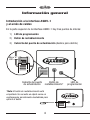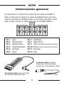
1
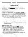
INSTALLATION INSTRUCTIONS ASWC-1
ASWC-1
Axxess Steering Wheel Control
Interface Installation Manual
US.PAT.NOS.8014920and8214105
Features
OneInterfacedoesitall-Noadditionalinterfacesneeded
Designedtobecompatiblewithallmajorradiobrands
Autodetectsvehicletype,radioconnection,andpresetscontrols
Abilitytodualassignsteeringwheelcontrolbuttons
Canbemanuallyprogrammedformostvehicles
Memoryretainssettingsevenafterbatterydisconnection
orinterfaceremoval
• Allconnectionsdoneattheradiolocation
• Micro“B”USBupdatable
InterFace components
•ASWC-1Interface•12-pinharnesswithmale3.5mm
connector•Female3.5mmconnectorwithBrownand
Brown/Whitewires•12k-ohmresistor
tools requIred
•Cuttingtool•Crimpingtool•Tape
METRA. THE WORLD’S BEST KITS.™
1-800-221-0932
metraonline.com
© COPYRIGHT 2004-2011 METRA ELECTRONICS CORPORATION
REV. 3/27/2014 ASWC-INST10
•
•
•
•
•
•
Table of Contents
Preface .............................................................................................. 3
Overview
– IntroductiontotheASWC-1InterfaceandWiringHarness ..............4-5
ASWC-1 Installation
– ConnectionstobeMade ................................................................6-7
– Programming.................................................................................8-9
AutoDetectMode:Overview........................................................ 8
AutoDetectMode:Steps ..........................................................8-9
– RemappingtheSWC(steeringwheelcontrol)Buttons ................10-11
ButtonAssignmentLegend ........................................................ 11
– ChangingRadioType .................................................................12-13
RadioLegend ............................................................................ 13
– DualAssignmentInstructions .....................................................14-15
DualAssignmentLegend ........................................................... 15
ASWC-1 Troubleshooting
– AutoDetectMode ......................................................................16-18
– ManualProgrammingMode .......................................................19-21
ManualProgrammingLegend.................................................... 21
– ResettingOriginalASWC-1Settings ................................................ 22
– LEDFeedback............................................................................22-23
Caution: Metra recommends disconnecting the negative battery terminal
before beginning any installation. All accessories, switches, and especially
air bag indicator lights must be plugged in before reconnecting the battery or
cycling the ignition.
2
Preface
What you need to know before you begin
1) Knowthecorrectyear,make,andmodelofyourvehicle.
2) Ensurethesteeringwheelcontrolsworkbeforeremovingthefactory
radio,andknowwhattheVolume Upbuttonis.TheVolume Up
buttonisusedforprogramming,soknowingthisbeforeremoving
theradioiscrucial.
Note: Steering wheel controls must be the ones that came with the
vehicle when purchased. We do not support custom work, i.e. adding
a new steering wheel with added/new buttons.
3) GototheAxxesswebsite(axxessinterfaces.com)andclickonthe
linkentitled“ASWC-1VehicleInstructions”,whichislocatedonthe
rightsideofthescreeninthemiddle.Onceyouputyourvehicle
informationin,clickthe“Submit”button.Thiswilltakeyouto
anotherpage,whereyouwillthenclickonthelinkundertheword
“Documents”.Thiswillprovidethevehiclespecificinstructions
foryourvehicle.Printthisdocumentsoyouhaveitwithyouinthe
vehicleduringtheinstallasitisthebest,andmostrecent
sourceofinformation.
4) Besurethattheradioyouareinstallingiscompatiblewiththe
ASWC-1.Additionally,refertotheRadioLegend(p.13)andyour
radio’sownersmanual.
5) UpdatetheASWC-1tothelatestsoftware.Note: To update go to
axxessinterfaces.com and download the WebXXpress program.
Attention: Even though we have done extensive research and testing
to verify that the steering wheel control wires we list are correct. It is
your responsibility to verify the steering wheel control wires we list are
correct with a multimeter. If you find an error, please notify our Axxess
Tech department at 1-800-253-TECH. Please be in the vehicle, parked,
along with access to the interface and vehicle wiring when you call.
3
Overview
Introduction to the ASWC-1 Interface
and Wiring Harness
OnthetopoftheASWC-1interfacetherearethreepointsofinterest:
1) Programming LED
2) Reset Button
3) Update Port Cover(slidetoopen)
Micro “B”
USB
UpdatePortCover
ResetButton*
*Note: The Reset button is recessed.
An item, such as a partially unfolded paper
clip, is needed to press the button.
4
ProgrammingLED
Overview
BelowarethewirecolorsfortheASWC-1.Pleasevisitthe Axxesswebsiteatwww.axxessinterfaces.comfordetailedinformation
onyourspecificvehicleandforwhatcolorwire(s)tousewiththe
ASWC-1interface.
Pin-1
Pin-2
Pin-3
Pin-4
Pin-5
Pin-6
Pink
White/Green
Yellow/Green
Green/Orange
Gray/Red
Black
Pin-7 Blue/Pink
Pin-8 Black/Green
Pin-9 Red(tip of 3.5mm connector)
Pin-10 White(ring of 3.5mm connector)
Pin-11 Gray/Blue
Pin-12 Red
Shown below: Female 3.5mm
connector with Brown (Br) and
Brown/White (Br/W) wires.
Br
Shown above: 12-pin harness with
male 3.5mm connector.
Br/W
5
ASWC-1 Installation
Connections to be made
Onceyouhavecollectedorprintedoutthe“ASWC-1VehicleInstructions”
foryourparticularvehicle,fromwww.axxessinterfaces.com,you’reready
toinstalltheASWC-1.
Note: If wiring is not available on our website for your vehicle, you will
need to obtain this yourself. Please check first with Axxess Tech Support
department at 1-800-253-TECH, as we may have this information.
Into vehicle:
1) ConnecttheBlackwireoftheASWC-1totheground.Youmayuse
thesamegroundingpointastheaftermarketradio;but
it is highly recommended to ground the ASWC-1 to the chassis,
of the vehicle, by itself.
2) Withthekeyintheoffposition,connecttheRedwireoftheASWC-1
tothe12-voltaccessorywire.
3) Locatethecorrectsteeringwheelcontrolwire(s)inthevehicle’s
harness,asdescribedinthe“ASWC-1VehicleInstructions”.Connect
thesewirestotheASWC-1.
Note: Metra recommends that the wires are soldered for
the best and most secure connection. Tapping style connectors
are not recommended due to a higher chance of a intermittent
connection or change in resistance values (which will cause the
ASWC-1 to fail to program).
Into radio:
1) Fortheradioslistedbelow,plugtheincludedfemale3.5mmadapter
(withtheBrownandBrown/Whitewires)intothemale3.5mm
connectoroftheASWC-1harness.
A. For Eclipse radios:ConnecttheEclipsesteeringwheelcontrol
wires(normallyBrownandBrown/Black)totheBrownand
Brown/WhitewiresoftheASWC-1.TheBrownoftheASWC-1
goestotheBrown/BlackoftheEclipseandBrown/Whiteofthe
ASWC-1goestotheBrownoftheEclipse.
6
ASWC-1 Installation
Connections to be made
B. For Metra OE radios:Connectthesteeringwheelcontrol
Key1wire(Gray)totheBrownwireoftheASWC-1.Isolateand
tapetheBrown/Whitewire,itwillnotbeused.
C. For Kenwood, or select JVC’s with a Blue/Yellow steering
wheel control wire:ConnecttheKenwood/JVCsteeringwheel
controlwiretotheBrownwireoftheASWC-1.Isolateandtape
theBrown/Whitewire,itwillnotbeused.
Note: Some of the newer Kenwood radios will auto detect as
a JVC. If this is the case, (a) use the included 12k ohm resistor
in-line between the Blue/Yellow and Brown wire of the female
3.5mm jack only during programming (remove resistor once
programmed) or (b) you can manually set the radio type, refer to
the Changing Radio Type section (pp. 12-13).
D. For XITE radios:ConnectthesteeringwheelcontrolSWC-2wire
fromtheradiototheBrownwireoftheASWC-1.Isolateandtape
theBrown/Whitewire,itwillnotbeused.
2) For Parrot Asteroid Smart or Tablets:Connectthe3.5mmjackof
theASWC-1intothefemale3.5mmjackoftheAX-SWC-PARROT
(soldseparately).Thenplugthe4-pinmaleharnessintothe
correspondingsteeringwheelcontrolfemaleharnessintheradio.
Note: AX-SWC-PARROT is required (sold separately) and the radio
must be updated to rev. 2.1.4 or higher. Additionally, the ASWC-1
must be updated to the most recent software available.
3) For all other radios:Pluginthemale3.5mmconnectorofthe
ASWC-1intothebackoftheaftermarketradio,designatedfor
anexternalsteeringwheelcontrolinterface.Pleaserefertothe
aftermarketradiosmanualifindoubtwherethe3.5mmconnector
oftheASWC-1goesinto.
7
ASWC-1 Installation
Programming
TheASWC-1canbeprogrammedtwodifferentways.Itcanauto
programitselfthroughAutoDetectMode,oritcanbemanually
programmed(pp.19-21).Thefollowing,whichisrecommended,isfor
autoprogramming.
Auto Detect Mode: Overview
TheASWC-1hastheabilitytoautodetectselectvehiclesandwhat
aftermarketradioitisconnectedto.The“ASWC-1VehicleInstructions”,
foundatwww.axxessinterfaces.com,willindicateifyourvehiclewillauto
detectandwhataction,ifany,isrequiredforthisprocesstotakeplace.
Fortheautodetectfeaturetoworkthereare(3)possibleactionsthatmust
betaken.Note,onlyoneactionwillberequireddependingonthevehicle:
1. Turntheignitiononandnootheractionisrequired.
--- Or --2. Turntheignitionon,pressandholdtheVolume Upbuttononthe
steeringwheel.
--- Or --3. Turntheignitionon,andthentaptheVolume Upbuttonrepeatedly
onthesteeringwheel.
Auto Detect Mode: Steps
Note: Please read all Auto Detect Mode steps before beginning.
1) Completeconnectionstothevehicleandtheaftermarketradio.
2) Turntheignitionon,theLEDwillstartrapidlyflashingRed;which
meanstheASWC-1islookingforthevehicleandtheradio.
Note: If the LED did not start flashing Red rapidly press the reset
button for 3 seconds and then proceed to Step 3.
3) Performactionrequiredforyourparticularvehicle,asnotedinthe
“ASWC-1VehicleInstructions”,downloadfromAxxessinterfaces.com.
8
ASWC-1 Installation
Programming
4) AfterafewsecondstheLEDshouldstopflashingrapidlyandgoout
forapproximately2seconds.Atthispointdonotpressanybuttons.
5) Aftertheapproximate2secondstherewillbeaseriesof7Green
flashes,someshort, andsomelong.Thelongflashesrepresentthe
wiresthatarerecognizedbytheASWC-1.
Tip: Knowing this will help if you need to troubleshoot; refer to p. 22,
for the appropriate LED Feedback section legend.
6) TheLEDwillpauseforanother2seconds,andthenflashRedupto
15timesdependingonwhatradioisconnectedtotheASWC-1.
Tip: Knowing this will help if you need to troubleshoot; refer to p. 23,
for the appropriate LED Feedback section legend.
7) Thisistheendoftheautodetectionstage.IftheASWC-1detected
thevehicleandtheradiosuccessfullytheLEDwilllightupsolid.
8) ForvehicleswithOEBluetoothbuttons,pressandholdthe
Hang uporPick upbuttononthesteeringwheelaftertheLEDon
theASWC-1goessolid.IftheOEBluetoothbuttonsareabletobe
usedtheLEDwillgooutafter3seconds.YourOEBluetoothbuttons
arenowprogrammedtoyouraftermarketradio.
Note: The aftermarket radio must have Bluetooth capability and must
be able to accept these commands.
9) Makesurethesteeringwheelcontrolbuttonsfunctioncorrectlyinthe
vehicleandenjoy.
Tip: If the ASWC-1 did not go to a solid LED, press the Reset button
for 3 seconds, release, and then start from Step 3. If the LED still doesn’t
go to a solid LED refer to the LED Feedback section (p. 22).This will help
you to determine if the ASWC-1 is detecting your vehicle. If not, refer to
the instructions starting on p. 6, and make sure all the instructions were
followed as stated. If you have done this and the ASWC-1 is still not going
to a solid LED please refer to the Troubleshooting section (pp. 16-18).
9
ASWC-1 Installation
Remapping the SWC buttons
Let’ssayyouhaveASWC-1programmedtoyourradioandyouwant
tochangethebuttonassignmentforthesteeringwheelcontrols.For
instance,youwouldlikeSeek UptobeMute.Followthestepsbelowto
remapthesteeringwheelcontrolbuttons:
1) MakesuretheASWC-1isvisible,soyoucanseetheLEDflashesto
confirmbuttonrecognition.
Tip: Turning off the radio is recommended.
2) Withinthefirst20secondsofturningtheignitionon, pressandholdtheVolume Upbuttononthesteeringwheeluntilthe
LEDgoessolid.
3) ReleasetheVolume UpbuttonandtheLEDwillgoout;Volume Up
hasnowbeenprogrammed.
4) FollowthelistintheButtonAssignmentLegend(p.11), toreferencetheorderinwhichthesteeringwheelcontrolbuttons
needtobeprogrammed.
Note: If the next function on the list is not on the steering wheel;
press the Volume Up button for 1 second, until the LED comes
on, and then release the button. This will tell the ASWC-1 that the
function is not available and it will move onto the next function.
5) Tocompletetheremappingprocess,pressandholdtheVolume Up
buttononthesteeringwheeluntiltheLEDontheASWC-1goesout.
10
ASWC-1 Installation
Remapping the SWC buttons
Button Assignment Legend
1.VolumeUp
8.PresetDown
2.VolumeDown
9.Power
3.SeekUp/Next
10.Band
4.SeekDown/Prev
11.Play/Enter
5.Source/Mode
12.PTT(PushtoTalk)*
6.Mute
13.OnHook
7.PresetUp
14.OffHook
*Only the following Pioneer models have the capability of retaining
this feature: AVIC-Z110BT, AVIC-Z120BT, AVIC-Z130BT, AVIC-Z140BT,
AVIC-X920BT, AVIC-X930BT, AVIC-X940BT.
Note: Not all radios will have all of these commands. Please refer to the
radio owner’s manual or contact the radio vendor directly for specific
commands recognized by that particular radio.
11
ASWC-1 Installation
Changing Radio Type
1) After3secondsofturningthekeyon,pressandholdtheVolume
DownbuttononthesteeringwheeluntiltheLEDontheASWC-1
goessolid.
2) ReleasetheVolume Downbutton;theLEDwillgooffindicatingwe
arenowinChangingRadioTypemode.
3) RefertotheRadioLegend(p.13)toknowwhichradionumberyou
wouldliketohaveprogrammed.
4) PressandholdtheVolume UpbuttonuntiltheLEDgoessolid,then
release.Repeatthisstepforthedesiredradionumberyouhave
selected.
5) Oncethedesiredradionumberhasbeenselected,pressandhold
theVolume Downbutton,onthesteeringwheel,untiltheLEDgoes
solid.TheLEDwillremainonforabout3secondswhileitstoresthe
newradioinformation.
6) OncetheLEDgoesofftheChangingRadioTypemodewillend.You
cannowtestthesteeringcontrolwheelcontrols.
Note: If at any time the user fails to press any button for a period
longer then 10 seconds this process will abort.
12
ASWC-1 Installation
Changing Radio Type
Radio Legend
1.Eclipse(Type1)
9. Valor
2.Kenwood
10.Clarion(Type2)
3.Clarion(Type1)
11.MetraOE
4.SonyandDual
12.Eclipse(Type2)
5.JVC
13.LG
6.PioneerandJensen
14.Parrot*
7.Alpine
15.XITE
8.Visteon
* AX-SWC-PARROT is required (sold separately) and the radio must
be updated to rev. 2.1.4 or higher. Additionally, the ASWC-1 must be
updated to the most recent firmware available.
Note: If you have a Clarion radio and the ASWC-1 did not work try the
other Clarion radio type, same for the Eclipse.
13
ASWC-1 Installation
Dual Assignment Instructions
Note: Seek Up and Seek Down are already set to Preset Up and
Preset Down for a long button press.
1) Turnontheignitionbutdonotstartthevehicle.
2) Pressandholddownthesteeringwheelbutton,thatyouwantto
assignalongpressfunction,forabout10secondsuntiltheLED
rapidlyflashesgreen.AtthispointreleasethebuttonandtheLED
willgosolidgreen.
3) Pressandreleasethe Volume Upbuttonthenumberoftimes
correspondingtothenewbuttonnumberselected(refertothechart
onp.15).ThegreenLEDwillblinkrapidlywhentheVolume Upis
pressedandbacktosolidgreenwhenreleased.Thengotothenext
stepwhentheVolume Upbuttonhasbeenpressedthedesired
numberoftimes.
Caution: If more than 10 seconds elapses between a Volume Up
button press this procedure will abort, and the LED will go off.
4) Tostorethelongpressbuttoninmemory,pressthebuttonthatyou
assignedalongpressbutton(thebuttonhelddowninStep1).The
LEDwillnowgooffindicatingithasbeenstored.
Note: These steps must be repeated for each button you would like to
assign dual purpose action to.
Toresetabutton,backtoitsoriginaluse,repeatStep1.Thenpressthe
Volume Downbutton.TheLEDwillgooffandthelongpressmapping
for thebuttonwillbeerased.
14
ASWC-1 Installation
Dual Assignment Instructions
Dual Assignment Legend
Button Number
New Button Action
1
Notallowed
2
Notallowed
3
SeekUp/Next
4
SeekDown/Prev
5
Mode/Source
6
Mute
7
PresetUp
8
PresetDown
9
Power
10
Band
11
Play/Enter
12
PTT
13
OnHook
14
OffHook
15
FanUp
16
FanDown
17
TempUp
18
TempDown
15
ASWC-1 Troubleshooting
Auto Detect Mode
IftheautodetectfeaturewastriedandattheendtheLEDdid
notgosolid,butinsteadcontinuallyflashes;thismeansthattheASWC-1
didnotdetectthevehicle.Followthesestepstodeterminewhatmay
havehappened:
1) Verifythatyouhavea12-voltDContheRedaccessorywireofthe
ASWC-1,usingamultimeter.
2) ReconfirmthatyouhaveagoodgroundtothesolidBlackwireof
theASWC-1.
Attention: Due to the nature of how microprocessors function,
sometimes having the ASWC-1’s ground shared and using the
factory ground in the OE wiring harness is not sufficient; and will
cause problems. The use of a chassis ground solely by itself is highly
recommended, especially in data communication vehicles. Attach
the solid Black wire of the ASWC-1 to a good chassis ground, all
by itself. Ensure this wire is straight from the ASWC-1 without any
extensions, and make sure a ring terminal (not supplied) is used, and
crimped properly. This will alleviate any grounding issues that may
keep the ASWC-1 from programming; most cases of the ASWC-1 not
programming comes from the lack of this step being done.
3) RecheckthatthewiresconnectedtotheASWC-1andvehicleare
correct;referencingthe“ASWC-1VehicleInstructions”document,
foundontheaxxessinterfaces.comwebsite.
4) VerifythatthewiresconnectedfromtheASWC-1tothevehicle
areconnecteddirect;i.e.,solder,crimpcap,militarysplice.No
tappingstyleconnectors,orbuttconnectorsarepermitteddueto
increasedresistance.
16
ASWC-1 Troubleshooting
Auto Detect Mode
Note: If a pre-wired harness is being used and you have tried all the
troubleshooting steps listed above, if the ASWC-1 still does not go
to a solid LED, remove the pre-wired ASWC-1 harness and use the
harness that came with the ASWC-1.
Ifyouhaveperformedanyofthestepsabove;reprogramtheASWC-1
bypressingtheresetbuttonontheASWC-1for3seconds,release,and
thenfollowtheinstructionsonp.9, startingfromStep3.IftheASWC-1
stilldoesnotgotoasolidLEDattheend,pleaserefertoManual
ProgrammingModeonpp.19-21tomanuallyprogramtheASWC-1.
IftheASWCdidgotoasolidLEDbutstilldoesnotwork,followthese
stepstotroubleshoottheradioprogrammingportionoftheauto
programmingsequence:
1) Confirmthatthe3.5mmjackonASWC-1isconnectedtoyour
radiosecurely,andinthecorrectjackoftheradio.Makesureitis
notpluggedintotheBluetoothmicorAUXjack.Ifyouarenotsure
whatjacktoconnecttotheradio,pleasecontacttheradiovendor.
Ifthewrongjackoftheradiowasconnectedto,correctit;andthen
reprogramtheASWC-1.
Note: Some radios do not use a jack for the steering wheel controls,
instead they use a wire. If so, reference Connections to be Made (p.
6), and ensure that you have the proper wire(s) connected.
2) Ifyouareusingaradiowithawireforconnectionsinsteadofajack,
makesureyouhavealsoprogrammedthesteeringwheelcontrolsto
theradiofollowingtheinstructionsincludedwiththeradio.Contact
theradiovendorifyouhaveanyquestionswiththis.
Note: This does not apply to JVC and Kenwood radios.
17
ASWC-1 Troubleshooting
Auto Detect Mode
3) For Kenwood radios,makesurethattheASWC-1displaysthata
Kenwoodradioisbeingused;referencetoRadioLegend(p.21).If
theRadioLegendshowsaJVCradioinstead,thenreferencetothe
ChangingRadioType(p.12)toforceprogramtheASWC-1to
displayKenwood.
Tip: Some Kenwood radios have a feature called Remote Sensor. If
your radio has this feature, ensure it is turned on. If it is on, turn it
off, then back on.
4) For Alpine radios,removethe3.5mmjackfromtheradio,
reprogramtheASWC-1withthejackremoved,andthenreconnect
the3.5mmjackbackintotheradio.
Tip: Some Alpine radios have a feature that turns the remote to
either the back, or the front. If you have one of these radios, ensure
the sensor is on the rear setting. If the setting is on the rear, turn it
to the front, then back to the rear.
5) For Pioneer and Sony radios,iftheASWC-1works,butthebuttons
areoutoforder,orbecomeoutoforder;thiscouldbecausedbythe
3.5mmjackontheASWC-1notseatingproperly,slippingout,ordirt
onthecontacts.Additionally,sometimesthiscanbeintermittent.
Removeanydirtonthecontacts,reinsertthejackfirmlyintothe
radio,andthenputastresslooponthe3.5mmcabletopreventthis
fromhappeninginthefuture.Also,ifanythingisprohibitingthejack
fromseatingallthewayin,suchasaheatsink,lightlytrimsomeof
theplasticfromthe3.5mmjackasneeded.
18
ASWC-1 Troubleshooting
Manual Programming Mode
IfyourvehicleisnotlistedforautodetectionbytheASWC-1on
theAxxesswebsite,www.axxessinterfaces.com,youmaybeableto
manuallyprogramanon-datacommunicationvehicleusingthe
followingsteps.
Tip: If you do not know if you have a data communication
vehicle or not, refer to the “ASWC-1 Vehicle Instruction” document,
from www.axxessinterfaces.com. If it indicates to press and release
the Volume Up button repeatedly to program the ASWC-1, then you
have a data communication vehicle.
Note: Not every radio will have all the possible steering wheel
control commands on the steering wheel. Aftermarket radios that
do not have Bluetooth will not recognize the PTT (Push to Talk) or
On/Off Hook commands, however these buttons may be able to be
manually programmed to do other commands. Please refer to the
radio owner’s manual or radio vendor for specific commands that
the radio will recognize.
Note: Please read all Manual Programming Steps before beginning.
1) FollowthestepsintheConnectionstobeMadesection(p.6-7)to
wireuptheASWC-1toyourradio.
2) Turntheignitionon,thenpressandholdtheResetbuttononthe
ASWC-1forapproximately10secondsuntiltheLEDontheASWC-1
flashesslow;andthenreleasetheResetbutton.
3) Atthispoint,pressandholdtheVolume Upbuttononthesteering
wheelfor7secondsuntiltheLEDgoessolid.Nowreleasethe
Volume Upbutton,andtheLEDwillgooff. Volume Uphasnow
beenprogrammed.
19
ASWC-1 Troubleshooting
Manual Programming Mode
4) Next,pressandholdtheVolume Downbuttonuntilthe
LEDgoessolid.ReleasetheVolume Down buttonandtheLED
willturnoff;Volume Downhasnowbeenprogrammed.
5) AtthispointrefertheManualProgrammingLegend(p.21)and
continuetotheSeek Up/Nextbutton.
Note: For any command that needs to be skipped, press the
Volume Up button for each one. The LED should light up each time
you press the Volume Up button.
6) Afterthelastbuttononyoursteeringwheelhasbeenprogrammed,
pressandholdtheVolume UpbuttonuntiltheLEDflashesslow;and
thenreleasetheVolume Upbutton.
Note: If at any time an error is made hold down the reset button on
the ASWC-1 for 10 or more seconds. This will restart the manual
programming. Go back to Step 4 and start again.
7) PressandholdtheVolume DownbuttonuntiltheLEDstartsto
flashquickly.
8) ReleasetheVolume Downbutton.
9) Afterapproximately4secondsoftheLEDflashingquicklytheLED
willgooutfor2seconds.
10) ThentheLEDwillflash,upto15times,dependingonwhatradio
isconnectedtotheASWC-1.
11) Makesurethenumberofflashesmatchwhatradioyouhave
installed.RefertotheRadioLegend(p.13).
Note: If the number of flashes do not match the radio you have
installed, refer to the Changing Radio Type section (p. 13).
20
ASWC-1 Troubleshooting
Manual Programming Mode
12) PressandholddowntheVolume DownbuttonuntiltheLED
goessolid.
13) Programmingforthevehicleandtheradioisnowcomplete.
Next,testthesteeringwheelcontrolfunctionstomakesureit
workscorrectly.
Manual Programming Legend
1.VolumeUp
10.Band
2.VolumeDown
11.Play/Enter
3.SeekUp/Next
12.PTT(PushtoTalk)
4.SeekDown/Prev
13.OnHook
5.Source/Mode
14.OffHook
6.Mute
15.FanUp
7.PresetUp
16.FanDown
8.PresetDown
17.TempUp
9.Power
18.TempDown
21
ASWC-1 Troubleshooting
Resetting Original ASWC-1 Settings
1) Turntheignitiononandwait3seconds.
2) PresstheResetbuttonfor3secondsandthenrelease.
3) RefertotheProgrammingsection(pp.8-9)toprogramtheASWC-1.
4) OncetheLEDissolidtheASWC-1isresetandshouldbeoperating
withthedefaultsettings.
ASWC-1 Troubleshooting
LED Feedback
A. Vehicle LED Feedback (indicatedbyGreenLEDontheASWC-1)
1st LEDflashistheWhite/Green
2nd LEDflashistheYellow/Green
3rd LEDflashistheGreen/Orange
4th LEDflashistheGray/Red
5th LEDflashistheBlack/Green
6th LEDflashistheGray/Blue
7th LEDflashisthePink
Note (section A):
• Short flashes represent the steering wheel control wire(s) that
are not connected to the vehicle from the ASWC-1.
• Long flashes represent wire(s) that are connected to the vehicle.
22
ASWC-1 Troubleshooting
LED Feedback
B. Radio LED Feedback (indicatedbyRedLEDontheASWC-1)
1st
2nd
3rd
4th
5th
6th
7th
8th
9th
10th
11th
12th
13th
14th
15th
LEDflashisforEclipse(Type1)
LEDflashisforKenwood
LEDflashisforClarion(Type1)
LEDflashisforSonyandDual
LEDflashisforJVC
LEDflashisforPioneerandJensen
LEDflashisforAlpine*
LEDflashisforVisteon
LEDflashisforValor
LEDflashisforClarion(Type2)
LEDflashisforMetraOE
LEDflashisforEclipse(Type2)
LEDflashisforLG
LEDflashisforParrot**
LEDflashisforXITE
*Note (section B): If the ASWC-1 flashes 7 times and you do not have an
Alpine radio connected to it that means that the ASWC-1 did not see any
radio connected. Verify the 3.5mm connector is connected to the steering
wheel control input into the radio.
**Note (section B): The AX-SWC-PARROT is required (sold separately).
The radio must be updated to rev. 2.1.4 or higher from www.parrot.com
and ASWC-1 must be updated to the latest firmware from
www.axxessinterfaces.com.
23
INSTALLATION INSTRUCTIONS ASWC-1
IMPORTANT WARNING
Thisproductincludesinstructionsforinstallationwhichmustbecarefully
followed.Theinstructionsarewordedinsuchamannertoassume
thattheinstalleriscapableofcompletingthesetypeofelectronic
installations.Ifyouareunclearastowhatyouareinstructedtodoor
believethatyoudonotunderstandtheinstructionssoastoproperlyand
safelycompletetheinstallationyou should consult a technician who
does have this knowledge and understanding.
Failure to follow these instructions carefully and to install the
interface as described could cause harm to the vehicle or to safety
systems on the vehicle. Interference with certain safety systems
could cause harm to persons as well. If you have any questions in
this regard please call the Help line or Metra at
1-800-221-0932 for assistance.
REV. 3/27/2014 ASWC-INST10
KNOWLEDGE IS POWER
Enhance your installation and fabrication skills by
enrolling in the most recognized and respected
mobile electronics school in our industry.
Log onto www.installerinstitute.com or call
800-354-6782 for more information and take steps
toward a better tomorrow.
Metra recommends MECP
certified technicians
US.PAT.NOS.8014920and8214105
1-800-221-0932
AxxESSINTERfACES.COM
© COPYRIGHT 2004-2011 METRA ELECTRONICS CORPORATION
INSTRUCCIONES DE INSTALACIÓN ASWC-1
ASWC-1
Manual de instalación de
la interfase de control en
volante Axxess
US.PAT.NOS.8014920y8214105
CaraCterístiCas
Componentes de la interfase
InterfaseASWC-1•Arnésde12pinsconconectormacho
de3.5mm•Conectorhembrade3.5mmconcables
marrón/blanco•Resistenciade12kohmios
Herramientas requeridas
•Cortador•Pelacables•Cinta
METRA. THE WORLD’S BEST KITS.™
1-800-221-0932
metraonline.com
© COPYRIGHT 2004-2011 METRA ELECTRONICS CORPORATION
REV. 4/15/2014 ASWC-INST10
• Unainterfasehacetodo-Noserequiereninterfasesadicionales
• Diseñadoparasercompatiblecontodaslasmarcas
principalesderadios
• Detectaautomáticamenteeltipodevehículo,laconexiónde
radioypreconfiguraloscontroles
• Sepuedenasignarbotonesdualesdecontrolenelvolante
• Sepuedeprogramarmanualmenteenlamayoríadelosvehículos
• Lamemoriaretienelaconfiguracióninclusodespuésdequese
desconectelabateríaoseeliminelainterfase
• Todaslasconexionessehacenenellugardelradio
• Actualizablepormicro“B”USB
Índice
Prefacio ............................................................................................. 3
Información general
– IntroductiontotheASWC-1InterfaceandWiringHarness ..............4-5
Instalación del ASWC-1
– Conexionesquesedebenhacer ....................................................6-7
– Programación ................................................................................8-9
Mododedetecciónautomática:Informacióngeneral ................... 8
Mododedetecciónautomática:Steps ......................................8-9
–RemapeodelosbotonesSWC ...................................................10-11
Leyendadeasignacióndebotones ............................................ 11
–Cambiodetipoderadio .............................................................12-13
Leyendaderadio ....................................................................... 13
–Instruccionesdeasignacióndual ...............................................14-15
Leyendadeasignacióndual ...................................................... 15
Resolución de problemas de ASWC-1
– Mododedetecciónautomática ..................................................16-18
– Mododeprogramaciónmanual .................................................19-21
ManualProgramaciónLegend ................................................... 21
– RestablecimientodelosajustesoriginalesdeASWC-1.................... 22
–RetroalimentaciónLED ..............................................................22-23
PRECAUCIÓN: Metra recomienda desconectar el terminal negativo de la batería
antes de comenzar cualquier instalación. Todos los accesorios, interruptores y,
especialmente, las luces indicadoras de airbag deben estar enchufados antes de
volver a conectar la batería o comenzar el ciclo de ignición.
Nota: Remítase a las instrucciones incluidas con el radio de postventa.
2
Prefacio
Lo que debe saber antes de empezar
1) Conozcaelaño,marcaymodelocorrectosdesuvehículo.
2) Asegúresedequeloscontrolesenelvolantefuncionenantesderetirar
elradiodefábricaysepacuáleselbotóndeaumentar volumen.El
botóndeaumentar volumenseusaparalaprogramación,asíquees
importantesaberestoantesderetirarelradio.
Nota: Los controles en el volante deben ser los que vienen con
el vehículo cuando este se compró. No aceptamos trabajos
personalizados, es decir, agregar un nuevo volante con botones
agregados/nuevos.
3) VisiteelsitiowebdeAxxess(axxessinterface.com)yhagaclicen
elenlacetitulado“ASWC-1VehicleInstructions”(Instruccionesdel
vehículoconASWC-1),ubicadoenlapartederechadelapantalla
enelcentro.Unavezqueingreselainformacióndesuvehículo,
hagaclicenelbotón“Submit”(Enviar).Estolollevaráaotra
página,dondeharáclicenelenlacebajolapalabra“Documents”
(Documentos).Estoleproporcionarálasinstruccionesespecíficas
alvehículoparasuvehículo.Imprimaestedocumentoparaquelo
tengaensuvehículodurantelainstalación,yaqueestaeslamejor
fuentedeinformación,ademásdeserlamásreciente.
4) Asegúresedequeelradioqueestáinstalandoseacompatiblecon
elASWC-1.Además,consultelaleyendadelradio(pág.13)yel
manualdelpropietariodesuradio.
5) ActualiceelASWC-1conelsoftwaremásreciente.Nota: Para
actualizarlo vaya a axxessinterfaces.com y descargue el programa
WebXXpress.
Atención: Auque hemos realizado una amplia investigación y pruebas
para verificar que los cables del control en el volante que enumeramos son
correctos. Es su responsabilidad verificar que los cables del control en el
volante que enumeramos sean correctos con un multímetro. Si encuentra
algún error, por favor notifique a nuestro Departamento Técnico de Axxess
al 1-800-253-TECH. Por favor llame desde su vehículo, mientras está
estacionado, y tenga acceso a la interfase y al cableado del vehículo cuando
realice la llamada.
3
Información general
Introducción a la interfase ASWC-1
y al arnés de cables
EnlapartesuperiordelainterfaseASWC-1haytrespuntosdeinterés:
1) LED de programación
2) Botón de restablecimiento
3) Cubierta del puerto de actualización(desliceparaabrirla)
Micro “B”
USB
Cubiertadelpuerto
Botónde
deactualización restablecimiento*
*Nota: El botón de restablecimiento está
empotrado. Se necesita un objeto como un
sujetapapeles parcialmente desdoblado para
oprimir el botón.
4
LEDde
programación
Información general
AcontinuaciónseindicanloscoloresdeloscablesdelASWC-1.
VisiteelsitiowebdeAxxessenwww.axxessinterfaces.compara
obtenerinformacióndetalladasobresuvehículoespecíficoypara
sabercuálescoloresdecablesusarconlainterfaseASWC-1.
Pin 1
Pin 2
Pin 3
Pin 4
Pin 5
Pin 6
Rosa
Blanco/Verde
Amarillo/Verde
Verde/Anaranjado
Gris/Rojo
Negro
Pin 7
Pin 8
Pin 9 Pin 10
Pin 11
Pin 12
Azul/Rosa
Negro/Verde
Rojo (punta del conector de 3.5mm)
Blanco (aro de conector de 3.5mm)
Gris/Azul
Rojo
Se muestra abajo: Conector
hembra de 3.5mm con cables
marrón (Br) y marrón/blanco (Br/W)
Br
Se muestra arriba: Arnés de 12 pins
con conector macho de 3.5mm
Br/W
5
Instalación del ASWC-1
Conexiones que se deben hacer
Unavezquehayarecolectadooimpresolas“Instruccionesdel
vehículoconASWC-1”sobresuvehículoespecíficoenelsitio
www.axxessinterface.com,estálistoparainstalarelASWC-1.
Nota: Si el cableado para su vehículo no está disponible en nuestro
sitio web, necesitará buscarlo por su cuenta. Confirme primero con el
departamento de soporte técnico de Axxess al 1-800-253-TECH, puesto
que nosotros podemos tener esta información.
Dentro del vehículo:
1) ConecteelcablenegrodelASWC-1atierra.Puedeusarelmismo
puntoatierraqueelradiodemercadosecundario,peroesmuy
recomendableconectarelASWC-1atierraconelchasísdel
vehículo,sincompartirlaconexión.
2) Conlallaveenlaposicióndeapagado,conecteelcablerojodel
ASWC-1conelcabledeaccesoriosde12voltios.
3) Localiceloscablescorrectosdelcontrolenelvolanteenelarnésdel
vehículo,segúnsedescribaenlas“Instruccionesdelvehículocon
ASWC-1”.ConecteestoscablesconelASWC-1.
Nota: Metra recomienda que los cables se suelden para lograr la
mejor conexión, y la más segura. No se recomienda usar conectores
de tipo rosca debido a que tienen una mayor probabilidad de crear
una conexión intermitente o un cambio en los valores de resistencia
(provocará que el ASWC-1 no se pueda programar).
Dentro del radio:
1) Paralosradiosenumeradosacontinuación,conecteeladaptador
hembrade3.5mm(conloscablesmarrónymarrón/blanco)al
conectormachode3.5mmdelarnésdelASWC-1.
A. Para radios Eclipse:Conecteloscablesdelcontrolenelvolante
Eclipse(normalmentemarrónymarrón/negro)conloscables
marrónymarrón/blancodelASWC-1.ElmarróndelASWC-1
seconectaalmarrón/negrodelEclipseyelmarrón/blancodel
ASWC-1seconectaconelmarróndelEclipse.
6
Instalación del ASWC-1
Conexiones que se deben hacer
B. Para radios Metra OE: ConecteelcableClave1(gris)delcontrol
enelvolanteconelcablemarróndelASWC-1.Aísleyencinteel
cablemarrón/blanco,noseutilizará.
C. Para Kenwood o algunos JVC con cable del control en el
volante azul/amarillo: Conecteelcabledelcontrolenelvolante
Kenwood/JVCconelcablemarróndelASWC-1.Aísleyencinteel
cablemarrón/blanco,noseutilizará.
Nota: Algunos de los radios Kenwood más nuevos se detectarán
automáticamente como JVC. Si este es el caso, (a) use la
resistencia de 12 k ohmios incluida en línea entre el cable azul/
amarillo y marrón del conector hembra de 3.5 mm únicamente
durante la programación (retire la resistencia después
programar) o (b) puede ajustar manualmente el tipo de radio,
consulte la sección Cambiar el tipo de radio (págs. 12 y 13).
D. Para radios XITE: ConecteelcableSWC-2delcontrolenel
volantedelradioalcablemarróndelASWC-1.Aísleyencinteel
cablemarrón/blanco,noseutilizará.
2) Para Parrot Asteroid Smart o tabletas:Conecteelconectorde3.5
mmdelASWC-1conelconectorhembrade3.5mmdelAX-SWCPARROT(sevendeporseparado).Luegoconecteelarnésmachode
4pinsconelcorrespondientearnéshembradelcontrolenelvolante
delradio.
Nota: Se requiere AX-SWC-PARROT (se vende por separado) y el
radio debe actualizarse a la versión 2.1.4 o más reciente. Además,
el ASWC-1 debe actualizarse al software más reciente disponible.
3) Para todos los demás radios:Conecteelconectormachode
3.5mmdelASWC-1enlaparteposteriordelradiodemercado
secundario,designadaparaunainterfasedecontrolenvolante
externo.Consulteelmanualdelosradiosdemercadosecundario
sitienedudasacercadedóndedebeirelconectorde3.5mm
delASWC-1.
7
Instalación del ASWC-1
Programación
ElASWC-1puedeprogramarsededosmanerasdiferentes.Puede
programarseautomáticamenteporsísolomedianteelmodode
detecciónautomáticaopuedeprogramarsemanualmente(págs.19a
21).Serecomiendalosiguienteparalaprogramaciónautomática.
Modo de detección automática: Información general
ElASWC-1tienelacapacidaddedetectarautomáticamentealgunos
vehículosyacuálradiodemercadosecundarioestáconectado.El
documento“InstruccionesdelvehículoconASWC-1”,queseencuentra
enelsitiowww.axxessinterface.com,indicarásisuvehículoserá
detectadoautomáticamenteyquéacción,dehaberla,debeseguirusted
paraqueesteprocesoselleveacabo.
Paraquelafuncióndedetecciónautomáticafuncionehay(3)acciones
posiblesquedebenllevarseacabo.Tengaencuentaquesolose
necesitaráunaaccióndependiendodelvehículo:
1. Enciendalaigniciónynoserequiereningunaotraacción.
--- O bien --2. Enciendalaignición,presioneymantengapresionadoelbotónde
aumentar volumenenelvolante.
--- O bien --3. Enciendalaigniciónyluegooprimaelbotóndeaumentar
volumenenelvolante.
Modo de detección automática: Pasos
Nota: Lea todos los pasos del modo de detección automática antes de
comenzar.
1) Realicelasconexionesalvehículoyalradiodemercadosecundario.
2) Enciendalaignición;elfocoLEDempezaráaparpadearrápidamente
decolorrojo,loquesignificaqueelASWC-1estábuscandoel
vehículoyelradio.
Nota: Si el foco LED no empezó a parpadear rápidamente de color rojo,
presione el botón de restablecimiento por 3 segundos y continúe con el
paso 3.
3) Realicelaacciónrequeridaparasuvehículoespecíficocomose
indicaeneldocumento“InstruccionesdelvehículoconASWC-1”,
quesedescargóenAxxessinterfaces.com.
4) Despuésdevariossegundos,elfocoLEDdebedejardeparpadear
8
Instalación del ASWC-1
Programación
ynoiluminarseduranteaproximadamente2segundos.Eneste
momento,nopresioneningúnbotón.
5) Despuésdeaproximadamente2segundos,habráunaseriede7
parpadeosdecolorverde,algunoscortosyalgunoslargos.Los
parpadeoslargosrepresentanloscablesquesonreconocidosporel
ASWC-1.
Sugerencia:Saberestoleayudaráencasodenecesitarresolver
problemas,consultelapágina22parabuscarlaleyendacorrectaen
lasecciónderetroalimentaciónLED.
6) ElfocoLEDpausaráduranteotros2segundosyluegoparpadearáde
colorrojohasta15vecesdependiendodelradioqueseconectóal
ASWC-1.
Sugerencia:Saberestoleayudaráencasodenecesitarresolver
problemas,consultelapágina23parabuscarlaleyendacorrectaen
lasecciónderetroalimentaciónLED.
7) Esteeselfinaldelaetapadedetecciónautomática.SielASWC1detectóelvehículoyelradiodeformaexitosa,elfocoLEDse
iluminarásinparpadear.
8) ParavehículosconbotonesBluetoothdelfabricanteoriginal,
presioneColgaroDescolgarenelcontroldesuvolantedespués
dequeelfocoLEDdelASWC-1seenciendasinparpadearSipueden
utilizarselosbotonesdeBluetoothdelfabricantedeequipooriginal,
elfocoLEDseapagarádespuésde3segundos.Losbotonesdesu
Bluetoothoriginalahoraestánprogramadosensuradiode
mercadosecundario.
Nota: El radio de mercado secundario debe ser compatible con
Bluetooth y debe ser capaz de aceptar estos comandos.
9) Asegúresedequelosbotonesdecontrolenelvolantefuncionen
correctamenteenelvehículoydisfrute.
Sugerencia: Si el foco LED del ASWC-1 no se enciende sin parpadear,
presione el botón de restablecimiento por 3 segundos, suéltelo y empiece
a partir del paso 3. Si el foco LED aún no se enciende sin parpadear
consulte la sección de retroalimentación LED (pág. 22). Esto le ayudará
a determinar si el ASWC-1 está detectando su vehículo. De lo contrario,
consulte las instrucciones empezando en la pág. 6 y asegúrese de seguir
todas las instrucciones como se indican. Si ha hecho esto y el ASWC-1
aún no se enciende sin parpadear, consulte la sección de resolución de
problemas (págs. 16 a 18).
9
Instalación del ASWC-1
Remapeo de los botones SWC
DigamosquetieneelASWC-1programadoparasuradioyahora
quierecambiarlaasignacióndelosbotonesparaloscontrolesdel
volante.Porejemplo,legustaríaqueelbotóndebuscar siguiente
funcionaracomosilencio.Sigaestospasospararemapearlosbotones
decontrolenelvolante:
1) AsegúresedetenerelASWC-1visible,paraquesepueda
verelparpadeodelfocoLEDparaconfirmarelreconocimientode
losbotones.
Sugerencia: Se recomienda apagar el radio.
2) Dentrodelosprimeros20segundosdespuésdeencenderla
ignición,presioneymantengapresionadoelbotóndeaumentar
volumendelvolantehastaqueelLEDdejedeparpadear.
3) Suelteelbotóndeaumentar volumenyelfocoLEDseapagará,
ahoraelbotóndeaumentar volumensehaprogramado.
4) Sigalalistaenlaleyendadeasignacióndebotones(pág.11),
paraconsultarelordenenquelosbotonesdelcontrolenelvolante
debenprogramarse.
Nota: Si la siguiente función de la lista no está en el volante, presione
el botón de aumentar volumen durante 1 segundo hasta que el foco
LED se encienda y luego suelte el botón. Esto le indica al ASWC-1 que
la función no está disponible y pasará a la siguiente función.
5) Paraterminarelprocesoderemapeo,presioneymantenga
presionadoelbotóndeaumentar volumenenelvolantehastaque
seapagueelfocoLEDenelASWC-1.
10
Instalación del ASWC-1
Remapeo de los botones SWC
Leyenda de asignación de botones
1.Subirvolumen
8.Bajarprestablecido
2.Bajarvolumen
9.Encendido
3.Buscarsiguiente
10.Banda
4.Buscaranterior
11.Reproducir/Aceptar
5.Fuente/Modo
12.PTT(presionarparahablar)
6.Silencio
13.Colgado
7.Subirprestablecido
14.Descolgado
*Solo los siguientes modelos Pioneer son capaces de retener esta
función: AVIC-Z110BT, AVIC-Z120BT, AVIC-Z130BT, AVIC-Z140BT,
AVIC-X920BT, AVIC-X930BT, AVIC-X940BT.
Nota: No todos los radios tienen todos estos comandos. Consulte el
manual del propietario del radio o comuníquese con el proveedor del
radio directamente para obtener los comandos específicos reconocidos
por ese radio en particular.
11
Instalación del ASWC-1
Cambio de tipo de radio
1) Despuésde3segundosdegirarlallaveaencendido,presioney
mantengapresionadoelbotóndebajar volumenenelvolante
hastaqueelfocoLEDenelASWC-1seenciendasinparpadear.
2) Suelteelbotóndebajar volumen,elfocoLEDseapagaráindicando
queahoraestamosenelmododecambiodetipoderadio.
3) Consultelaleyendaderadio(pág.13)parasaberquénúmerode
radiolegustaríaprogramar.
4) Presioneymantengapresionadoelbotóndeaumentar
volumenhastaqueelfocoLEDseenciendasinparpadear,luego
suéltelo.Repitaestepasoparaelnúmeroderadiodeseadoque
haseleccionado.
5) Despuésdeseleccionarelnúmeroderadiodeseado,presioney
mantengapresionadoelbotóndebajar volumenenelvolante
hastaqueelfocoLEDseenciendasinparpadear.ElfocoLED
permaneceráencendidoduranteaproximadamente3segundos
mientrasalmacenalainformacióndelnuevoradio.
6) DespuésdeapagarseelfocoLED,finalizaráelmododecambiode
tipoderadio.Ahorapuedeprobarloscontrolesenelvolante.
Nota: Si en cualquier momento el usuario no presiona ningún botón
por un periodo mayor a 10 segundos, este modo de programación
se abortará.
12
Instalación del ASWC-1
Cambio de tipo de radio
Leyenda de radio
1.Eclipse(Tipo1)
9. Valor
2.Kenwood
10.Clarion(Tipo2)
3.Clarion(Tipo1)
11.MetraOE
4.SonyandDual
12.Eclipse(Tipo2)
5.JVC
13.LG
6.PioneerandJensen
14.Parrot*
7.Alpine
15.XITE
8.Visteon
*Se requiere AX-SWC-PARROT (se vende por separado) y el radio debe
actualizarse a la versión 2.1.4 o más reciente. Además, el ASWC-1 debe
actualizarse al firmware más reciente disponible.
Nota: Si tiene un radio Clarion y el ASWC-1 no funcionó pruebe con el
otro tipo de radio Clarion, lo mismo aplica con el radio Eclipse.
13
Instalación del ASWC-1
Instrucciones de asignación dual
Nota: Los botones buscar siguiente y buscar anterior ya están
configurados en subir prestablecido y bajar prestablecido al presionar
y sostener el botón.
1) Enciendalaigniciónperonoenciendalamarchadelvehículo.
2) Presioneysostengaelbotóndelvolantealquedeseaasignara
unafuncióndepresionarysostener,durantealmenos10segundos
hastaqueelfocoLEDparpadeerápidamentedecolorverde.Eneste
momentosuelteelbotónyelfocoLEDseencenderásinparpadear.
3) Presioneysuelteelbotóndeaumentar volumenelnúmerode
vecesquecorresponda alnúmerodelnuevobotónseleccionado
(consultelatablaenlapág.15).ElfocoLEDdecolorverde
parpadearárápidamentecuandosepresionaelbotóndeaumentar
volumenyseencenderásinparpadeardecolorverdecuandose
suelta.Luegovayaalsiguientepasocuandoelbotóndeaumentar
volumensehapresionadoelnúmerodevecesdeseado.
Precaución: Si transcurren más de 10 segundos entre cada vez
que presiona el botón de aumentar volumen, este procedimiento
se abortará y se apagará el foco LED.
4) Paraalmacenarenlamemoriaelbotóndepresionarysostener,
presioneelbotónalqueasignócomobotóndepresionarysostener
(elbotónquesemantuvopresionadoenelpaso1).ElfocoLED
ahoraseapagaráindicandoquesehaalmacenado.
Nota: Estos pasos deben repetirse con cada botón al que le gustaría
asignar una acción de doble propósito.
Pararestablecerunbotónasuusooriginal,repitaelpaso1.Luego
presioneelbotóndebajar volumen.ElfocoLEDseapagaráyelmapeo
depresionarysostenerdeesebotónseborrará.
14
Instalación del ASWC-1
Instrucciones de asignación dual
Leyenda de asignación dual
Número de botón Nueva acción del botónn
1
Nosepermite
2
Nosepermite
3
Buscarsiguiente
4
Buscaranterior
5
Modo/Fuente
6
Silencio
7
Subirprestablecido
8
Bajarprestablecido
9
Potencia
10
Banda
11
Reproducir/Aceptar
12
PTT
13
Colgado
14
Descolgado
15
Aumentarventilador
16
Disminuirventilador
17
Aumentartemperatura
18
Disminuirtemperatura
15
Resolución de problemas de ASWC-1
Modo de detección automática
SilafuncióndedetecciónautomáticaseintentóyalfinalelfocoLED
noseencendiósinparpadear,sinoqueparpadeócontinuamente;esto
significaqueelASWC-1nodetectóelvehículo.Sigaestospasospara
determinarquépuedehaberocurrido:
1) Verifiquequetenga12voltiosdeCDenelcablerojodeaccesorios
delASWC-1,usandounmultímetro.
2) VuelvaaconfirmarqueelcablenegrodelASWC-1tieneuna
conexiónatierracorrecta.
Atención: Debido a la naturaleza del funcionamiento de los
microprocesadores, algunas veces compartir la conexión a tierra del
ASWC-1 y usar la conexión a tierra de fábrica del arnés de cables
original no es suficiente, y ocasionará problemas. Se recomienda
ampliamente usar la tierra al chasís sin compartir especialmente
en vehículos con comunicación de datos. Sujete el cable negro del
ASWC-1 a tierra del chasís sin compartir esta conexión. Asegúrese de
que el cable venga directamente del ASWC-1 sin ninguna extensión,
y asegúrese de usar una terminal de aro (no suministrada) y que esté
correctamente pelada. Esto resolverá cualquier problema de conexión
a tierra que pudiera impedir la programación del ASWC-1; en la
mayoría de los casos el ASWC-1 no se programa debido a la omisión
de este paso.
3) VuelvaarevisarqueloscablesconectadosalASWC-1yel
vehículoseanloscorrectos,consulteeldocumento“Instrucciones
delvehículoconASWC-1”queseencuentraenelsitioweb
axxessinterfaces.com.
4) VerifiquequeloscablesconectadosdelASWC-1alvehículo
seconectendirectamente,esdecir,soldadura,tapaderosca,
empalmedeuniónoccidental.Nosepermiteelusodeconectoresde
tiporoscaoconectoresatopedebidoaqueaumentanlaresistencia.
16
Resolución de problemas de ASWC-1
Modo de detección automática
Nota: Si se usa un arnés precableado y ha intentado todos los pasos
de resolución de problemas mencionados anteriormente, si foco
LED del ASWC-1 aún no se enciende sin parpadear, retire el arnés
precableado del ASWC-1 y use el arnés que venía con el ASWC-1.
Siharealizadocualquieradelospasosanteriores,vuelvaaprogramar
elASWC-1presionandoelbotónderestablecimientoenelASWC-1
durante3segundos,suélteloyluegosigalasinstruccionesenlapágina
9empezandoapartirdelpaso3.SielfocoLEDdelASWC-1aúnnose
enciendesinparpadearalfinal,consulteelmododeprogramaciónmanual
enlaspáginas19a21paraprogramarelASWC-1manualmente.
SielfocoLEDdelASWCseenciendesinparpadearperoaúnno
funciona,sigaestospasospararesolverlosproblemasdelapartede
programacióndelradiosobrelasecuenciadeprogramación:
1) Confirmequeelconectorde3.5mmenelASWC-1estéconectado
firmementeasuradioyqueestéenelconectorcorrectodelradio.
Asegúresedequenoestéconectadoalconectoraux,micoBluetooth.
Sinoestáseguroquéconectordebeconectaralradio,comuníquese
conelproveedordelradio.Siseconectóelconectorequivocadodel
radio,corríjaloyluegovuelvaaprogramarelASWC-1.
Nota: Algunos radios no usan un conector para los controles en el
volante más bien usan un cable. Si es así, consulte la sección de
conexiones que se deben hacer (pág. 6) y asegúrese de que haya
conectado los cables correctos.
2) Siestáusandounradioconuncableparalasconexionesenvez
deunconector,asegúresedequetambiénhayaprogramadolos
controlesenelvolantealradiosiguiendolasinstruccionesquese
incluyenconelradio.Comuníqueseconelproveedordelradiosi
tienecualquierdudasobreesto.
Nota: Esto no aplica a los radios JVC y Kenwood.
17
Resolución de problemas de ASWC-1
Modo de detección automática
3) Para los radios Kenwood, asegúresedequeelASWC-1muestre
queseestáusandounradioKenwood,consulteleyendadelradio
(pág.21).SialcontrariolaleyendadelradiomuestraradioJVC,
entoncesconsulteelcambiodetipoderadio(pág.12)paraobligar
alprogramadelASWC-1amostrarKenwood.
Sugerencia: Algunos radios Kenwood tienen una función
llamada Sensor de control remoto. Si su radio tiene esta función,
asegúrese de que está encendida. Si está encendida, apáguela y
vuélvala a encender.
4) Para radios Alpine, retireelconectorde3.5mmdelradio,vuelva
aprogramarelASWC-1sinelconector,yluegovuelvaaconectarel
conectorde3.5denuevoconelradio.
Sugerencia: Algunos radios Alpine tienen una función que cambia
el control remoto a la parte posterior o frontal. Si tiene uno de estos
radios, asegúrese de que el sensor esté en el ajuste trasero. Si el
ajuste está en la parte trasera, cámbielo a la parte frontal y luego de
nuevo a la parte trasera.
5) Para radios Pioneer y Sony, sielASWC-1funcionaperolos
botonesnoestánfuncionandoodejandefuncionar,estopodría
deberseaqueelconectorde3.5mmdelASWC-1noestábien
colocado,seestádesconectandoohaysuciedadenloscontactos.
Además,algunasvecesestopuedeserintermitente.Retiretodala
suciedaddeloscontactos,vuelvaainsertarelconectorfirmemente
enelradioyluegocoloqueunbucleenelcablede3.5mmpara
evitarqueestosucedaenelfuturo.Asimismo,sialgoestáevitando
queelconectorentreporcompleto,talcomoundisipador,recorte
ligeramenteunpocoelplásticodelconectorde3.5según
seanecesario.
18
Resolución de problemas de ASWC-1
Modo de programación manual
Sisuvehículonoseencuentraenlalistadeladetecciónautomáticadel
ASWC-1enelsitiowebdeAxxess,www.axxessinterfaces.com,esposible
quepuedaprogramarmanualmenteunvehículosincomunicaciónde
dadosusandolossiguientespasos.
Sugerencia: En caso de no saber si tiene un vehículo con
comunicación de datos, consulte el documento “Instrucciones
del vehículo con ASWC-1” en el sitio web www.axxessinterfaces.
com. Si indica presionar y soltar el botón de aumentar volumen
repetidamente para programar el ASWC-1, entonces usted tiene un
vehículo con comunicación de datos.
Nota: No todos los radios tendrán todos los comandos posibles
en control en el volante. Los radios de mercado secundario que
no tengan Bluetooth no reconocerán los comandos PPT (presionar
para hablar) o de teléfono colgado o descolgado; sin embargo,
estos botones pueden programarse manualmente para realizar
otros comandos. Consulte el manual del propietario del radio o el
proveedor del radio para ver los comandos específicos que el radio
puede reconocer.
Nota: Lea todos los pasos de programación manual antes de comenzar.
1) Sigalospasosenlaseccióndeconexionesquesedebenhacer
(pág.6y7)paraconectarloscablesdelASWC-1consuradio.
2) Enciendalaignición,luegopresioneymantengapresionadoelbotón
derestablecimientoenelASWC-1duranteaproximadamente10
segundoshastaqueelfocoLEDdelASWC-1parpadeelentamentey
luegosuelteelbotónderestablecimiento.
3) Enestemomento,presioneymantengapresionadoelbotónde
aumentar volumenenelvolantedurante7segundoshastaque
elfocoLEDseenciendasinparpadear.Ahorasuelteelbotónde
aumentar volumenyelfocoLEDseapagará.Yaquedóprogramado
elbotónquesubeelvolumen.
19
Resolución de problemas de ASWC-1
Modo de programación manual
4) Ahorapresioneymantengapresionadoelbotóndebajar volumen
hastaqueelfocoLEDseenciendasinparpadear.Suelteelbotónde
bajar volumenyelfocoLEDseapagará,yaquedóprogramadoel
botóndebajar volumen.
5) Enestemomentoconsultelaleyendadeprogramaciónmanual(pág.
21)ycontinúeconelbotónBuscar siguiente.
Nota: Para cualquier comando que necesite omitirse, presione
el botón de aumentar volumen por cada uno. El foco LED debe
encenderse cada vez que presione el botón de aumentar volumen.
6) Despuésdeprogramarelúltimobotónenelvolante,presione
ymantengapresionadoelbotóndeaumentar volumenhastaque
elfocoLEDparpadeelentamenteyluegosuelteelbotónde
aumentar volumen.
Nota: Si en cualquier momento se equivoca, mantenga presionado
el botón de restablecimiento en el ASWC-1 durante 10 segundos
o más. Esto reiniciará la programación manual. Vuelva al Paso 4 y
empiece de nuevo.
7) Presioneymantengapresionadoelbotóndebajar volumenhasta
queelfocoLEDempieceaparpadearrápidamente.
8) Suelteelbotóndebajar volumen.
9) Despuésdeaproximadamente4segundosdequeelfocoLED
parpadeerápidamente,esteseapagarádurante2segundos.
10) LuegoelfocoLEDparpadearáhasta15veces,dependiendodel
radioalqueelASWC-1estáconectado.
11) Asegúresedequelacantidaddeparpadeoscorrespondaalradio
quetieneinstalado.Consultelaleyendadelradio(pág.13).
20
Resolución de problemas de ASWC-1
Modo de programación manual
Nota: Si el número de parpadeos no coincide con el radio que ha
instalado, consulte la sección de cambio de tipo de radio (pág. 13).
12) Presioneymantengapresionadoelbotóndebajar volumenhasta
queelfocoLEDseiluminesinparpadear.
13) Laprogramacióndelvehículoydelradiohafinalizado.Ahora,
pruebelasfuncionesdelcontrolenelvolanteparaasegurarsede
quefuncionencorrectamente.
Leyenda de la programación manual
1.Subirvolumen
10.Banda
2.Bajarvolumen
11.Reproducir/Aceptar
3.Buscarsiguiente
12.PTT(presionarparahablar)
4.Buscaranterior
13.Colgado
5.Fuente/Modo
14.Descolgado
6.Silencio
15.Aumentarventilador
7.Subirprestablecido
16.Disminuirventilador
8.Bajarprestablecido
17.Aumentartemperatura
9.Encendido
18.Disminuirtemperatura
21
Resolución de problemas de ASWC-1
Restablecimiento de los ajustes
originales de ASWC-1
1) Enciendalaigniciónyespere3segundos.
2) Presioneelbotónderestablecimientodurante3segundosy
luegosuéltelo.
3) Consultelaseccióndeprogramación(páginas8y9)para
programarelASWC-1.
4) DespuésqueelfocoLEDseenciendasinparpadear,elASWC-1se
restablecióydebefuncionarconlosajustespredeterminados.
Resolución de problemas de ASWC-1
Retroalimentación LED
A. Retroalimentación LED del vehículo (indicadaporelfocoLED
decolorverdeenelASWC-1)
El1er
El2o
El3er
El4o
El5o
El6o
El7o
parpadeodelfocoLEDeselblanco/verde
parpadeodelfocoLEDeselamarillo/verde
parpadeodelfocoLEDeselverde/anaranjado
parpadeodelfocoLEDeselgris/rojo
parpadeodelfocoLEDeselnegro/verde
parpadeodelfocoLEDeselgris/azul
parpadeodelfocoLEDeselrosa
Nota (section A):
• Los parpadeos cortos representan el o los cables del control en el
volante que no están conectados al vehículo desde el ASWC-1.
• Los parpadeos largos representan el o los cables que están conectados
al vehículo.
22
Resolución de problemas de ASWC-1
Retroalimentación LED
B. Retroalimentación LED del radio (indicadaporelfocoLEDde
colorrojoenelASWC-1)
El1er
El2o
El3er
El4o
El5o
El6o
El7o
El8o
El9o
El10o
El11vo
El12vo
El13vo
El14vo
El15vo
parpadeodelfocoLEDesparaEclipse(Tipo1)
parpadeodelfocoLEDesparaKenwood
parpadeodelfocoLEDesparaClarion(Tipo1)
parpadeodelfocoLEDesparaSonyyDual
parpadeodelfocoLEDesparaJVC
parpadeodelfocoLEDesparaPioneeryJensen
parpadeodelfocoLEDesparaAlpine*
parpadeodelfocoLEDesparaVisteon
parpadeodelfocoLEDesparaValor
parpadeodelfocoLEDesparaClarion(Tipo2)
parpadeodelfocoLEDesparaMetraOE
parpadeodelfocoLEDesparaEclipse(Tipo2)
parpadeodelfocoLEDesparaLG
parpadeodelfocoLEDesparaParrot**
parpadeodelfocoLEDesparaXITE
*Nota (sección B): Si el ASWC-1 parpadea 7 veces y no tiene un radio
Alpine conectado a él, esto significa que el ASWC-1 no detectó ningún
radio conectado. Verifique que el conector de 3.5mm esté conectado a la
entrada del control en el volante en el radio.
**Nota (sección B): Se requiere de AX-SWC-PARROT (se vende por
separado). El radio debe estar actualizado a la versión 2.1.4 o más reciente
en www.parrot.com y el ASWC-1 debe estar actualizado al firmware más
reciente del sitio web www.axxessinterfaces.com.
23
INSTRUCCIONES DE INSTALACIÓN ASWC-1
ADVERTENCIA IMPORTANTE
Esteproductoincluyeinstruccionesdeinstalaciónquedebenseguirse
cuidadosamente.Dichasinstruccionesestánredactadasdandopor
supuestoqueelinstaladorescapazdecompletarestostiposde
instalacioneselectrónicas.Sitienedudasrespectodeloquesele
indicaquehagaocreequenocomprendelasinstruccionescomopara
completarlainstalaciónenformaadecuadaysegura,debeconsultara
untécnicoqueefectivamentetengaestosconocimientosycomprensión.
Si no sigue estas instrucciones con cuidado y no instala la
interfaz como se describe, podría provocar daños en el vehículo
o en los sistemas de seguridad del vehículo. La interferencia con
determinados sistemas de seguridad también podría provocar
daños a las personas. Si tiene alguna pregunta al respecto,
llame a la línea de ayuda o a metra, al 1-800-221-0932 para
obtener asistencia.
REV. 4/15/2014 ASWC-INST10
CONOCIMIENTO ES PODER
KEL
NOWLEDGE
IS POWER
Mejoresushabilidadesdeinstalaciónyfabricación
Enhance your installation and fabrication skills by
inscribiéndoseenlaescueladedispositivos
enrolling
in the most recognized and respected
mobile
electronics school in our industry.
electrónicosmóvilesmásreconocidayrespetadade
Log onto www.installerinstitute.com or call
nuestraindustria.Regístreseenwww.installerinstitute.
800-354-6782 for more information and take steps
comollameal800-354-6782paraobtenermás
toward
a better tomorrow.
informaciónyavancehaciaunfuturomejor.
Metra recomienda técnicos con
certificación del Programa de
Certificación en Electrónica Móvil
(Mobile Electronics Certification
Program, MECP).
US.PAT.NOS.8014920y8214105
1-800-221-0932
AxxESSINTERfACES.COM
© COPYRIGHT 2004-2011 METRA ELECTRONICS CORPORATION