1
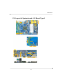
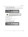
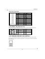
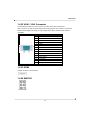
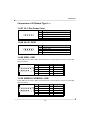
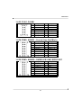
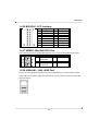
K3780E Mainboard K3780E AMD 780E + AMD SB710 K3780E-S / K3780E-D (Type1) K3780E-S Single Core CPU AMD Sempron 210U (1.5GHz) K3780E-D Dual Core CPU AMD Athlon™ Neo X2 L325 (1.5GHz) K3780E-S2 / K3780E-D2 (Type2) K3780E-S2 Single Core CPU AMD Sempron 210U (1.5GHz) K3780E-D2 Dual Core CPU AMD Athlon™ Neo X2 L325 (1.5GHz) User's Manual Ver. 1.0 MB Dimension 170mm x 148mm Operating System ® Windows XP/ Vista/ Win7 Release Date 091229 I Mainboard Things You Have To Know 0 The images and pictures in this manual are for reference only and may vary from the product you received depending on specific hardware models, third party components and software versions. 0 This mainboard contains very delicate IC chips. Always use a grounded wrist strap when working with the system. 0 Do not touch any IC chip, lead, connector or other components. 0 Always unplug the AC power when you install or remove any device on the mainboard or when configuring pins and switches. Symbols Attention- Important Follow the procedures Troubleshooting Tips Refer to other II Mainboard Index CHAPTER 1 GETTING STARTED........................................................................................... 1 1.1 INTRODUCTION ................................................................................................................ 1 1.2 SPECIFICATION ................................................................................................................ 2 1.2.1 CPU .................................................................................................................................. 2 1.2.2 Chipset.............................................................................................................................. 2 1.2.3 Memory ............................................................................................................................. 2 ® 1.2.4 Audio - Realtek ALC 662 ................................................................................................. 2 ® 1.2.5 LAN - Realtek RTL8111C................................................................................................ 3 1.2.6 Slot.................................................................................................................................... 3 1.2.7 Mini-IDE Connector........................................................................................................... 3 1.2.8 I/O Connectors .................................................................................................................. 3 1.2.9 Universal Serial Bus.......................................................................................................... 4 1.2.10 SATA II............................................................................................................................ 4 1.2.11 BIOS ............................................................................................................................... 4 1.2.12 Hardware Monitor............................................................................................................ 4 1.2.13 Power Supply .................................................................................................................. 4 1.3 CONFIGURATION .............................................................................................................. 5 1.3.1 Layout of System board + I/O Board Type 1 ..................................................................... 5 1.3.2 Layout of System board + I/O Board Type 2 ..................................................................... 6 1.4 HARDWARE INSTALLATION ................................................................................................ 7 Jumpers ..................................................................................................................................... 7 Jumpers of System Board --- ..................................................................................................... 7 1.4.1 FPSWLED: Front Panel Headers...................................................................................... 7 1.4.2 JP1: Clear CMOS Jumper................................................................................................. 8 1.4.3 JU1: SPI Program Enable ................................................................................................. 8 Jumpers of I/O Board Type 1 --- ................................................................................................ 9 1.4.4 JP1: CF Card Master/ Slave Jumper................................................................................. 9 1.4.5 JP2: LVDS VDD POWER ................................................................................................. 9 1.4.6 CN1 - 6: RS-232 Voltage Setting ...................................................................................... 9 Jumpers of I/O Board Type 2 --- .............................................................................................. 10 1.4.7 JP1001: CF Card Master/ Slave Jumper......................................................................... 10 1.4.8 JP2001: LVDS VDD POWER ......................................................................................... 10 1.4.9 CN1/ CN2: RS-232 Voltage Setting ................................................................................ 10 Connectors............................................................................................................................... 11 Connectors of System Board ---............................................................................................... 11 1.4.10 J1 - J4: SATA ................................................................................................................ 11 1.4.11 FAN1: FAN Header ....................................................................................................... 11 1.4.12 PWR1: ATX Power Connector ...................................................................................... 12 1.4.13 DDRII1/ DDRII2: Memory Installation............................................................................ 13 Connectors of I/O Board Type 1 ---.......................................................................................... 14 1.4.14 J3/ J4: PGIO ................................................................................................................. 14 1.4.15 J5: 4 Pin Power Conn. .................................................................................................. 14 1.4.16 USB1/ USB2: USB ........................................................................................................ 14 III Mainboard 1.4.17 COM 1/ 2 & COM4~7: COM Port .................................................................................. 15 1.4.18 CON6: LVDS................................................................................................................. 15 1.4.19 U16: Print Port .............................................................................................................. 16 1.4.20 KBMS1: Mini-DIN PS/2 Port.......................................................................................... 16 1.4.21 USBLAN1/USBLAN2: LAN +USB Port ......................................................................... 16 1.4.22 VGA1: VGA Connector ................................................................................................. 17 1.4.23 HDMI............................................................................................................................. 17 1.4.24 SNDCN1 ....................................................................................................................... 17 1.4.25 MINI_PCI1: Mini PCI Slot.............................................................................................. 18 1.4.26 CON5: CF Card Connector ........................................................................................... 18 Connectors of I/O Board Type 2 ---.......................................................................................... 19 1.4.27 J2: 4 Pin Power Conn. .................................................................................................. 19 1.4.28 J4/ J5: PGIO ................................................................................................................. 19 1.4.29 USB1: USB ................................................................................................................... 19 1.4.30 USB2001/ USB2002: USB ............................................................................................ 19 1.4.31 COM 1/ 2: COM Port..................................................................................................... 20 1.4.32 CON1001: LVDS........................................................................................................... 20 1.4.33 C1001: D-SUB .............................................................................................................. 21 1.4.34 CON2: AUDIO1 - Line In/ Line Out/ Mic In.................................................................... 21 1.4.35 CON3: AUDIO2 - SURR/ LFE/ CNE/ SPDIF OUT ........................................................ 21 1.4.36 BIOSCN1: LPC Interface .............................................................................................. 22 1.4.37 KBMS1: Mini-DIN PS/2 Port.......................................................................................... 22 1.4.38 USBLAN1: LAN +USB Port........................................................................................... 22 1.4.39 HDMI1001..................................................................................................................... 23 1.4.40 DVI1001 ........................................................................................................................ 23 1.4.41 CON2005: CF Card Connector ..................................................................................... 23 CHAPTER 2 BIOS SETUP ..................................................................................................... 24 2.1 MAIN MENU ................................................................................................................... 24 2.1.1 Standard CMOS Features............................................................................................... 25 2.1.2 Advanced BIOS Features ............................................................................................... 26 2.1.3 Advanced Chipset Features............................................................................................ 27 2.1.4 Integrated Peripherals..................................................................................................... 28 2.1.5 Power Management Setup.............................................................................................. 29 2.1.6 PnP/PCI Configurations .................................................................................................. 30 2.1.7 PC Health Status............................................................................................................. 31 2.1.8 Load Fail-Safe Defaults................................................................................................... 32 2.1.9 Load Optimized Defaults................................................................................................. 33 2.1.10 Set Supervisor Password.............................................................................................. 34 2.1.11 Set User Password ....................................................................................................... 35 2.1.12 Save & Exit Setup ......................................................................................................... 36 2.1.13 Exit Without Saving ....................................................................................................... 37 CHAPTER 3 SOFTWARE SETUP ......................................................................................... 38 3.1 SOFTWARE INSTALLATION .............................................................................................. 38 IV K3780E Mainboard Chapter 1 Getting Started 1.1 Introduction Thanks for choosing K3780E Mainboard. It is based on AMD 780E Northbridge chipset and AMD SB710 Southbridge chipset. In addition, it also supports integrated AMD 780E Graphics Engine for onboard graphics feature. It supports CPU as below: K3780E-S / K3780E-D (Type1) K3780E-S Single Core CPU AMD Sempron 210U (1.5GHz) K3780E-D Dual Core CPU AMD Athlon™ Neo X2 L325 (1.5GHz) K3780E-S2 / K3780E-D2 (Type2) K3780E-S2 Single Core CPU AMD Sempron 210U (1.5GHz) K3780E-D2 Dual Core CPU AMD Athlon™ Neo X2 L325 (1.5GHz) The K3780E provides 1 x Single channel SO-DIMM DDR2 800MHz by Single Core CPU up to 2GB; 2 x Dual channel SO-DIMM DDR2 800MHz by Dual Core CPU up to 4GB SO-DIMM. This mainboard provides one MINI-IDE connector for MINI-IDE hard drives, supporting Ultra ATA 100/66/33MHz. and support 4 SATA II (300MB/s). In addition, PCI-E x16 Slot, Mini PCI & CF II (optional) slot for use is also allowed. The K3780E provides LVDS, HDMI, VGA (D-Sub) or DVI, 8 or 4 USB 2.0/ 1.1 and 6 or 2 RS232 ports for use. There are maximal 8 USB2.0/ 1.1 ports which can be set up on this mainboard. This mainboard also comes with one onboard 10/100/1000 Mbps Ethernet LAN chips (RTL8111C). On the back panel of your case that you can directly plug into Internet cables. ® The Realtek ALC 662 AC’97 Codec supports high quality performance. 1 Mainboard 1.2 Specification 1.2.1 CPU K3780E-S / K3780E-D (Type1) K3780E-S Single Core CPU AMD Sempron 210U (1.5GHz) K3780E-D Dual Core CPU AMD Athlon™ Neo X2 L325 (1.5GHz) K3780E-S2 / K3780E-D2 (Type2) K3780E-S2 Single Core CPU AMD Sempron 210U (1.5GHz) K3780E-D2 Dual Core CPU AMD Athlon™ Neo X2 L325 (1.5GHz) 1.2.2 Chipset Northbridge Chipset - AMD 780E Southbridge Chipset - AMD SB710 Super I/O Controller - W83627UHG IO RS-232 Controller - W83627UHG AC’97 Audio Codec - Realtek ALC 662 LAN Controller - PCI-E Realtek RTL8111C ® ® 1.2.3 Memory 1 or 2 DDR II SO-DIMM socket 1 x Single channel SO-DIMM DDR2 800MHz by Single Core CPU up to 2GB 2 x Dual channel SO-DIMM DDR2 800MHz by Dual Core CPU up to 4GB 1.2.4 Audio - Realtek® ALC 662 Compliant with AC’97 2.3 specification Support SPDIF output (cable by optional) Support 3D stereo enhancement 2 Mainboard 1.2.5 LAN - Realtek® RTL8111C ® PCI-E Realtek Giga LAN Ethernet LAN RJ45 Connector with link/act and speed LED integrated K3780E I/O Board Type I: 2 x LAN K3780E I/O Board Type II: 1 x LAN 1.2.6 Slot K3780E I/O Board Type I 1 x PCI-E x16 Slot 1 x Mini-PCI Slot 1.2.7 Mini-IDE Connector One Mini-IDE Connector for two Mini-IDE 44pin hard disk drives CF card type I/II Ultra ATA 33/66/100 MHz High capacity hard disk drives 1.2.8 I/O Connectors One Mini-DIN PS/2 connector K3780E I/O Board Type I 1 x LVDS 1 x D-Sub 1 x HDMI 6 x COM header (6 ports by optional cable) Realtek 6 Channel HD Audio K3780E I/O Board Type II 1 x LVDS 1 x DVI or D-Sub (D-Sub by optional cable) 1 x HDMI 2 x COM header (2 ports by optional cable) Realtek 6 Channel HD Audio; Audio output header (by optional cable) 3 Mainboard 1.2.9 Universal Serial Bus K3780E I/O Board Type I: 8 x USB 2.0 2 x USB 2.0/1.1 header (4 ports by optional cable) K3780E I/O Board Type II: 4 x USB 2.0 1 x USB 2.0/1.1 header (2 ports by optional cable) 1.2.10 SATA II 4 x SATA II (300MB/s) SATA RAID 0, 1, 10 1.2.11 BIOS Phoenix-Award™ BIOS 1.2.12 Hardware Monitor Monitor CPU temperature and FAN speed Monitor system voltages 1.2.13 Power Supply ATX 24 pin power 1 x 5V/ 12V 4 pin power connector (K3780E I/O Board Type I) 4 Mainboard 1.3 Configuration 1.3.1 Layout of System board + I/O Board Type 1 5 Mainboard 1.3.2 Layout of System board + I/O Board Type 2 6 Mainboard 1.4 Hardware Installation This section will assist you in quickly installing your system hardware. Wear a wrist ground strap before handling components. Electrostatic discharge may damage the system's components. Jumpers Jumpers of System Board --1.4.1 FPSWLED: Front Panel Headers Pin 1 Assignment HDD LED (+) LED Hard Drive LED (HD_LED) 3 HDD LED (-) 5 Reset Control (+) Reset Switch Reset Control (-) (RST_SW) 7 9 N/A LED Pin 2 Assignment Power LED (+) 4 Power LED (-) 6 8 Power Switch (+) Power-on Switch Power Switch (-) (PWR_SW) 10 N/C Power LED (ACPI_LED) HD_LED (Hard Drive LED ) If your case front panel has a hard drive LED cable, attach it to this header. The LED will flicker when there is hard disk drive activity. ACPI_LED (2 pin Power LED) This header can be attached to the power LED cord from the case front panel onto this header, then the power LED will illuminate while the system is powered on. RST_SW (Reset Switch) This header can be attached to a momentary SPST switch (reset button) cable on your case front panel. The switch is normally left open. When the switch closed, it will cause the mainboard to reset and run the POST (Power-On Self Test). PWR_SW (Power-on Switch) This header can be attached to a power switch cable on your case front panel. You can turn your system on or off by pressing the button attached to this power switch cable. 7 Mainboard 1.4.2 JP1: Clear CMOS Jumper The "Clear CMOS" function is used when you are unable boot your system and need to reset the BIOS settings (CMOS settings) back to the manufacturer's original settings. This is also a way to reset the system password if you have forgotten it. JP3 Assignment Pin 1-2 Closed Normal (Default) Pin 2-3 Closed Clear CMOS Data Note: "Closed" means putting a jumper cap onto two adjacent header pins. The following steps explain how to reset your CMOS configurations when you forgot a system password. 1. Turn off your system and disconnect the AC power cable. 2. Set JP3 header to OFF (2-3 Closed). 3. Wait several seconds. 4. Set JP3 header to ON (1-2 closed). 5. Connect the AC power cable and turn on your system. 6. Reset your new password. 1.4.3 JU1: SPI Program Enable This Jumper is to select the SPI Program device. JP2 Assignment Pin 1-2 Closed Normal (Default) Pin 2-3 Closed EXT. PROGRAMMING 8 Mainboard Jumpers of I/O Board Type 1 --1.4.4 JP1: CF Card Master/ Slave Jumper This Jumper is to select the CF works on Secondary Channel master device or Slave device. JP2 Assignment Pin 1-2 Closed Slave Pin 2-3 Closed Master (Default) 1.4.5 JP2: LVDS VDD POWER It’s for LVDS VDD power setting. JP3 Assignment Pin 1-2 Closed VCC5V Pin 2-3 Closed VCC3P3V (Default) 1.4.6 CN1 - 6: RS-232 Voltage Setting Pin 1 3 5 Assignment RS232 RS232 RS232 Pin 2 4 6 9 Assignment VCC5V RI (Default) VCC12V Mainboard Jumpers of I/O Board Type 2 --1.4.7 JP1001: CF Card Master/ Slave Jumper This Jumper is to select the CF works on Secondary Channel master device or Slave device. JP2 Assignment Pin 1-2 Closed Slave Pin 2-3 Closed Master (Default) 1.4.8 JP2001: LVDS VDD POWER It’s for LVDS VDD power setting. JP3 Assignment Pin 1-2 Closed VCC5V Pin 2-3 Closed VCC3P3V (Default) 1.4.9 CN1/ CN2: RS-232 Voltage Setting Pin 1 3 5 Assignment RS232 RS232 RS232 10 Pin 2 4 6 Assignment VCC5V RI (Default) VCC12V Mainboard Connectors Connectors of System Board --1.4.10 J1 - J4: SATA Pin 1 2 3 4 5 6 7 Assignment GND SATA_TX+ SATA_TXGND SATA_RX+ SATA_RXGND 1.4.11 FAN1: FAN Header There is one fan header available for cooling fan. This cooling fan plays an important role in maintaining ambient temperatures in your system. Pin 1 2 3 Assignment GND +12V SENSER 11 Mainboard 1.4.12 PWR1: ATX Power Connector This mainboard provides one ATX connector. You must attach it before the system is powered on. This power connector supports several power management functions such as the instant power-on function. The connector pins are described below. Pin 13 14 15 16 17 Assignment 3.3V -12V COM PS-ON COM Pin 1 2 3 4 5 Assignment 3.3V 3.3V COM +5V COM 18 COM 6 +5V 19 COM 7 COM 20 -5V 8 PWR-OK 21 +5V 9 5VSB 22 +5V 10 12V 23 +5V 11 12V 24 COM 12 3.3V 12 Mainboard 1.4.13 DDRII1/ DDRII2: Memory Installation It provides DDR SO-DIMM socket which allows you to install 200-pin SO-DIMM. Memory Installation Steps: 1. Match the notch on the bottom of the DIMM module with the corresponding pattern in the DIMM slot. This will ensure that the module will be inserted with the proper orientation. Now the chips or pins at the bottom of the DIMM module are still visible. 2. Lower the DIMM module into the DIMM Slot until the chips or pins at the bottom of the DIMM module are hidden. 3. Press the DIMM module backward firmly using both thumbs until the module snaps into place. Do not use excessive force. 4. Repeat steps 1, 2 & 3 for the remaining DIMM modules. * The pictures above are for reference only. Your actual installation may vary slightly from the pictures.。 13 Mainboard Connectors of I/O Board Type 1 --1.4.14 J3/ J4: PGIO Pin 1 2 3 4 Assignment FPGA_TDI FPGA_TMS INITB GND 1.4.15 J5: 4 Pin Power Conn. Pin 1 2 3 4 Assignment FPGA_TDI FPGA_TMS INITB GND 1.4.16 USB1/ USB2: USB These USB ports are used to attach with USB devices, such as keyboard, mouse and other USB supported devices. Pin 1 3 5 7 9 Assignment +5V STB USBUSB+ GND N/C 14 Pin 2 4 6 8 10 Assignment +5V STB USBUSB+ GND N/A Mainboard 1.4.17 COM 1/ 2 & COM4~7: COM Port This mainboard provides four COM pin headers for you to connect additional serial connectors on your case back panel. Attach cables of serial connectors onto these headers, then you can use the serial connectors connecting with a mic, modem or other peripheral device. Pin 1 3 5 7 9 Assignment DCD SOUT GND RTS +5V/RINGW/ +12V Pin 2 4 6 8 10 Assignment SIN DTR DSR CTS N/C 1.4.18 CON6: LVDS Pin 2 4 6 8 10 Assignment 12V GND 3.3V/5V GND/I2C_CLK Assignment 12V GND 3.3V/5V GND/ I2C_DATA BCKLITE_ON Pin 1 3 5 7 9 12 LVDS_GND 11 LVDS_GND 14 CHB_TX0+ 13 CHA_TX0+ 16 CHB_TX0- 15 CHA_TX0- 18 LVDS_GND 17 LVDS_GND 20 CHB_TX1+ 19 CHA_TX1+ 22 CHB_TX1- 21 CHA_TX1- 24 LVDS_GND 23 LVDS_GND 26 CHB_TX2+ 25 CHA_TX2+ 28 CHB_TX2- 27 CHA_TX2- 30 LVDS_GND 29 LVDS_GND 32 CHB_TXC+ 31 CHA_TXC+ 34 CHB_TXC- 33 CHA_TXC- 36 LVDS_GND 35 LVDS_GND 38 CHB_TX3+ 37 CHA_TX3+ 40 CHB_TX3- 39 CHA_TX3- 15 BRIGHTNESS Mainboard 1.4.19 U16: Print Port Pin 1 3 5 7 9 11 13 15 17 19 21 23 25 Assignment RSTBRPDR0 RPDR1 RPDR2 RPDR3 RPDR4 RPDR5 RPDR6 RPDR7 ACKBUSY PE SLCT Pin 2 4 6 8 10 12 14 16 18 20 22 24 26 Assignment RAFDERRRIVIT-PKSLINGND GND GND GND GND GND GND GND GND 1.4.20 KBMS1: Mini-DIN PS/2 Port This mainboard provides a standard Mini-DIN PS/2 port to connect PS/2 keyboard and mouse. Pin 1 3 5 Assignment Keyboard/ Mouse data GND Keyboard/ Mouse clock Pin 2 4 6 Assignment N/C 5V GND 1.4.21 USBLAN1/USBLAN2: LAN +USB Port ® There is one PCI-E Realtek Giga Ethernet LAN port available for you to attach Internet cables. These USB ports are used to attach with USB devices, such as keyboard, mouse and other USB supported devices. 16 Mainboard 1.4.22 VGA1: VGA Connector The mainboard provides one VGA connector (= D-Sub connector) on back panel. VGA connector (= D-Sub connector) delivers the analogy signals, and is able to connect with traditional CRT display, flat display, or other display device which with the D-Sub interface compatible. Pin 1 2 3 4 5 6 7 8 9 10 Assignment RED GREEN BLUE N/A GND GND GND GND NVGA03 GND 11 N/A 12 DDC_DATA 13 5VHSYNC 14 5VVSYNC 15 DDC_CLK 1.4.23 HDMI A HDMI connector is the serial port. 1.4.24 SNDCN1 17 Mainboard 1.4.25 MINI_PCI1: Mini PCI Slot Mini PCI (Peripheral Component Interconnect) is a 32-bit, 33MHz bus standard for integrated peripherals of smaller products. The mainboard provides one Mini PCI slot available to install expansion cards such as network card, SCSI card, etc. 2 1 1.4.26 CON5: CF Card Connector The mainboard provides one CF card connector (CompactFlash I/II Card). 18 Mainboard Connectors of I/O Board Type 2 --1.4.27 J2: 4 Pin Power Conn. Pin 1 2 3 4 Assignment FPGA_TDI FPGA_TMS INITB GND Pin 1 2 3 4 Assignment FPGA_TDI FPGA_TMS INITB GND 1.4.28 J4/ J5: PGIO 1.4.29 USB1: USB These USB ports are used to attach with USB devices, such as keyboard, mouse and other USB supported devices. Pin 1 3 5 7 9 Assignment +5V STB USBUSB+ GND N/C Pin 2 4 6 8 10 Assignment +5V STB USBUSB+ GND N/A 1.4.30 USB2001/ USB2002: USB These USB ports are used to attach with USB devices, such as keyboard, mouse and other USB supported devices. Pin 1 3 5 7 9 Assignment +5V STB USBUSB+ GND N/C 19 Pin 2 4 6 8 10 Assignment +5V STB USBUSB+ GND N/A Mainboard 1.4.31 COM 1/ 2: COM Port This mainboard provides four COM pin headers for you to connect additional serial connectors on your case back panel. Attach cables of serial connectors onto these headers, then you can use the serial connectors connecting with a mic, modem or other peripheral device. Pin 1 3 5 7 9 Assignment DCD SOUT GND RTS +5V/RINGW/ +12V Pin 2 4 6 8 10 Assignment SIN DTR DSR CTS N/C 1.4.32 CON1001: LVDS Pin 2 4 6 8 10 Assignment 12V GND 3.3V/5V GND/I2C_CLK Assignment 12V GND 3.3V/5V GND/ I2C_DATA BCKLITE_ON Pin 1 3 5 7 9 12 LVDS_GND 11 LVDS_GND 14 CHB_TX0+ 13 CHA_TX0+ 16 CHB_TX0- 15 CHA_TX0- 18 LVDS_GND 17 LVDS_GND 20 CHB_TX1+ 19 CHA_TX1+ 22 CHB_TX1- 21 CHA_TX1- 24 LVDS_GND 23 LVDS_GND 26 CHB_TX2+ 25 CHA_TX2+ 28 CHB_TX2- 27 CHA_TX2- 30 LVDS_GND 29 LVDS_GND 32 CHB_TXC+ 31 CHA_TXC+ 34 CHB_TXC- 33 CHA_TXC- 36 LVDS_GND 35 LVDS_GND 38 CHB_TX3+ 37 CHA_TX3+ 40 CHB_TX3- 39 CHA_TX3- 20 BRIGHTNESS Mainboard 1.4.33 C1001: D-SUB Pin 1 3 5 7 9 11 13 Assignment N/A N/A HSYNC VHYNC VGA_R VGA_G VGA_B Pin 2 4 6 8 10 12 14 Assignment N/A N/A DDC_CLK DDC_DATA N/A N/A N/A 1.4.34 CON2: AUDIO1 - Line In/ Line Out/ Mic In Pin 1 3 5 7 9 11 13 15 Assignment LINE1_L LINE1_R GND FRONT_L FRONT_R GND MIC_L MIC_R Pin 2 4 6 8 10 12 14 16 Assignment LINE1_JD GND GND FRONT_JD GND GND MIC_JD GND 1.4.35 CON3: AUDIO2 - SURR/ LFE/ CNE/ SPDIF OUT Pin 1 3 5 7 9 11 13 15 Assignment GND SURR_L SURR_R GND LFE CEN GND VCC5V 21 Pin 2 4 6 8 10 12 14 16 Assignment GND SURR_JD GND GND LFE_JD GND GND SPIDF_OUT Mainboard 1.4.36 BIOSCN1: LPC Interface Pin 1 3 5 7 9 11 13 15 Assignment LAD0 LAD1 LAD2 LAD03 VCC3P3V GND VCC5V VCC12V Pin 2 4 6 8 10 12 14 16 Assignment LDRQ SERIRQ LPCCLK LPCRST LFRAME 48MHZ VCC5V VCC12V 1.4.37 KBMS1: Mini-DIN PS/2 Port This mainboard provides a standard Mini-DIN PS/2 port to connect PS/2 keyboard and mouse. Pin 1 3 5 Assignment Keyboard/ Mouse data GND Keyboard/ Mouse clock Pin 2 4 6 Assignment N/C 5V GND 1.4.38 USBLAN1: LAN +USB Port ® There is one PCI-E Realtek Giga Ethernet LAN port available for you to attach Internet cables. These USB ports are used to attach with USB devices, such as keyboard, mouse and other USB supported devices. 22 Mainboard 1.4.39 HDMI1001 A HDMI connector is the serial port. 1.4.40 DVI1001 A DVI connector is the serial port. 1.4.41 CON2005: CF Card Connector The mainboard provides one CF card connector (CompactFlash I/II Card). 23 K3780E Mainboard Chapter 2 BIOS Setup 2.1 Main Menu The Award BIOS (Basic Input/Output System) installed in your computer system’s. The BIOS provides for a standard device such as disk drives, serial ports and parallel ports. It also adds password protection as well as special support for detailed fine-tuning of the chipset controlling the entire system. The Award BIOS provides a Setup utility program for specifying the system configurations and settings. The BIOS ROM of the system stores the Setup utility. When you turn on the computer, the Award BIOS is immediately activated. Pressing the <Del> key immediately allows you to enter the Setup utility. If you a little bit late press the <Del> key, POST (Power On Self Test) will continue with its test routines, thus preventing you from invoking the Setup. If you still wish to enter Setup, restart the system by pressing the “Reset” button or simultaneously pressing the <Ctrl>, <Alt> and <Delete> keys. You can also restart by turning the system Off and back On again. The following message will appear on the screen: Press <DEL> to Enter Setup In general, you press the arrow keys to highlight items, <Enter> to select, the <PgUp> and <PgDn> keys to change entries, <F1> for help and <Esc> to quit. When you enter the Setup utility, 24 Mainboard the Main Menu screen will appear on the screen. The Main Menu allows you to select from various setup functions and exit choices. 2.1.1 Standard CMOS Features Include all the adjustable items in standard compatible BIOS. 25 Mainboard 2.1.2 Advanced BIOS Features Include all the adjustable items of Award special enhanced features. 26 Mainboard 2.1.3 Advanced Chipset Features Include all the adjustable items of chipset special features. 27 Mainboard 2.1.4 Integrated Peripherals Include all onboard peripherals. 28 Mainboard 2.1.5 Power Management Setup Include all the adjustable items of Green function features. 29 Mainboard 2.1.6 PnP/PCI Configurations Include all configurations of PCI and PnP resources. 30 Mainboard 2.1.7 PC Health Status It is for monitoring the system status such as temperature, voltage, and fan speeds. 31 Mainboard 2.1.8 Load Fail-Safe Defaults It can load Fail-Safe defaults except standard CMOS setup. 32 Mainboard 2.1.9 Load Optimized Defaults It can load the preset system parameter values to set the system in its best performance configurations. 33 Mainboard 2.1.10 Set Supervisor Password Set change or disable password. It allows you to limit access to the system and/or BIOS setup. 34 Mainboard 2.1.11 Set User Password Set change or disable password. It allows you to limit access to the system and/or BIOS setup. 35 Mainboard 2.1.12 Save & Exit Setup Save CMOS value settings to CMOS and exit setup. Typing “Y”, you will quit the setup utility and save all the changes into the CMOS memory. Typing “N”, you will return to Setup utility. 36 Mainboard 2.1.13 Exit Without Saving Abandon all CMOS value changes and exit setup. Typing “Y” will quit the Setup utility without saving the modifications. Typing “N” will return you to Setup utility. 37 Mainboard Chapter 3 Software Setup 3.1 Software Installation Place the Driver CD into the CD-ROM drive and the Installation Utility will auto-run. You can also launch the Driver CD Installation Utility manually by executing the program located on the Driver CD. (For more details, please refer to the Readme.txt files that in each folder of the Driver.) Driver for XP/ Vista/ Vista 64/ Win7/ Win7 64 Driver for XP 64 ◎The screen and images are only for general reference. The version of the screens you received with your software may vary slightly. 38 Mainboard When you insert the driver CD into the CD-ROM, you'll see the screen as the picture below. There are several driver buttons displayed in the "Driver Menu" screen, and you can click on the drivers to install. Chipset Driver - It provides the driver of VGA. LAN Driver - It provides the driver of Network. HDMI Driver - It provides the driver of HDMI. Audio Driver - It provides the driver of Audio CODEC. Click on the "User Manual" button, you can choose the manual to read. If you click the "Browse CD" button, you can browse all the files in the Driver CD. Attention Before you read manuals, you must install the driver of Adobe Acrobat Reader 6 to browse PDF files.。 39