1
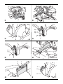
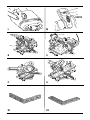
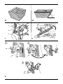
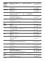
www.
.eu
DW712
DW712N
English (original instructions)
8
Copyright DEWALT
2
19
1
18
17
16
2
15
13
14
11
3
12
10
9
8
7
4
5
6
A1
1
26
25
24
23
27
28
29
31
30
32
A2
2
35
36
A4
A5
14 13
18
37
3
30
11
A6
30
B
17
40
2
40
40
C
E1
42 44
E2
43
45
42 43 45
2
E3
3
47
46
45
48 49
26
45 43 16
E4
E5
5
4
F1
50
F2
53
47
53
51
3
F3
6
52
53
F4
54 55
4
56
G
4
H
57
47
51
11
I1
I2
3
52
59
58
10
28
I3
I4
3
29
58
9
60
I5
J1
76
8
61
27
62
63
J2
K
5
65
64
1
19
DW712
L
M
13
20
6
N
O
P
Q
R1
R2
A
S1
S2
67
15
31
67
66
67
12
T
U
2
1
20
3
V
7
EN GL I S H
MITRE SAW DW712, DW712N
Congratulations!
Vibration total values (triax vector sum) determined according to EN 61029:
You have chosen a DEWALT tool. Years of experience, thorough
product development and innovation make DEWALT one of the most
reliable partners for professional power tool users.
Vibration emission value ah
ah =
Uncertainty K =
Technical Data
The vibration emission level given in this information sheet has been
measured in accordance with a standardised test given in EN 61029
and may be used to compare one tool with another. It may be used for
a preliminary assessment of exposure.
Voltage
(UK & Ireland only)
Type
Power output
Current input (230V)
Current input (115V)
Blade diameter
Blade bore
Max. blade thickness
Blade speed
Max. crosscut capacity at 90/90°
Max. mitre cut capacity at 45˚
Max. depth of cut 90˚
Max. depth of bevel cross-cut 45˚
Mitre (max. positions)
V
V
W
A
A
mm
mm
mm
min-1
mm
mm
mm
mm
DW712
DW712 DW712N DW712N
QS/CH
LX
QS/GB
LX
230
_
230
_
230/115
115 230/115 115
5
5
3
3
1600
1600
1600
1600
8
8
8
8
16
16
16
16
216
216
216
216
30
30
30
30
1.8
1.8
1.8
1.8
3500–4600 3500–4600 5400
5400
300 x 70 300 x 70 300 x 70 300 x 70
212
212
212
212
70
70
70
70
50
50
50
50
m/s²
m/s²
2.1
1.5
2.1
1.5
2.1
1.5
2.1
1.5
WARNING: The declared vibration emission level
represents the main applications of the tool. However if
the tool is used for different applications, with different
accessories or poorly maintained, the vibration emission
may differ. This may significantly increase the exposure level
over the total working period.
An estimation of the level of exposure to vibration should
also take into account the times when the tool is switched
off or when it is running but not actually doing the job. This
may significantly reduce the exposure level over the total
working period.
Identify additional safety measures to protect the operator
from the effects of vibration such as: maintain the tool and
the accessories, keep the hands warm, organisation of
work patterns.
left
right
50˚
60˚
50˚
60˚
50˚
60˚
50˚
60˚
FFuses
Europe
U.K. & Ireland
U.K. & Ireland
left
right
48˚
2˚
48˚
2˚
48˚
2˚
48˚
2˚
NOTE: This device is intended for the connection to a power supply
system with maximum permissible system impedance Zmax of 0.28 Ω
at the interface point (power service box) of user’s supply.
Bevel (max. positions)
0° mitre
Resulting width at
max. height 70 mm
Resulting height at
max. width 300 mm
45° mitre left
Resulting width at
max. height 70 mm
Resulting height at
max. width 212 mm
45° mitre right
Resulting width at
max. height 70 mm
Resulting height at
max. width 212 mm
45° bevel left
Resulting width at
max. height 50 mm
Resulting height at
max. width 300 mm
31.62° mitre, 33.85° bevel
Resulting height at
max. width 254 mm
Blade stopping time
Dust collection efficiency
Weight
mm
s
mg/m
kg
65
< 10
< 2.0
21
65
< 10
< 2.0
21
65
< 10
< 2.0
21
65
< 10
< 2.0
21
LPA
KPA
LWA
KWA
dB(A)
dB(A)
dB(A)
dB(A)
91
3.0
104
2.9
91
3.0
104
2.9
91
3.0
104
2.9
91
3.0
104
2.9
mm
300
300
300
300
mm
70
70
70
70
mm
212
212
212
212
mm
70
70
70
70
mm
212
212
212
212
mm
70
70
70
70
mm
300
300
300
300
mm
50
50
50
50
230 V tools
230 V tools
115 V tools
10 Amperes, mains
13 Amperes, in plugs
16 Amperes, mains
The user has to ensure that this device is connected only to a power
system which fulfils the requirement above. If necessary, the user can
ask the public power supply company for the system impedance at the
interface point.
Definitions: Safety Guidelines
The definitions below describe the level of severity for each signal word.
Please read the manual and pay attention to these symbols.
DANGER: Indicates an imminently hazardous situation
which, if not avoided, will result in death or serious injury.
WARNING: Indicates a potentially hazardous situation
which, if not avoided, could result in death or serious
injury.
CAUTION: Indicates a potentially hazardous situation
which, if not avoided, may result in minor or moderate
injury.
NOTICE: Indicates a practice not related to personal
injury which, if not avoided, may result in property
damage.
Denotes risk of electric shock.
Denotes risk of fire.
EC-Declaration of Conformity
DW712, DW712N
8
(sound pressure)
(sound pressure uncertainty)
(sound power)
(sound power uncertainty)
DEWALT declares that these products described under technical data
are in compliance with:
2006/42/EC, EN 61029-1, EN 61029-2-9.
These products also comply with Directive 2004/108/EC and 2011/65/
EU. For more information, please contact DEWALT at the following
address or refer to the back of the manual.
ENGLI SH
The undersigned is responsible for compilation of the technical file and
makes this declaration on behalf of DEWALT.
12. Secure work.
Where possible use clamps or a vice to hold the work. It is safer
than using your hand and it frees both hands to operate the tool.
13. Do not overreach.
Keep proper footing and balance at all times.
14. Maintain tools with care.
Horst Grossmann
Vice President Engineering and Product Development
DEWALT, Richard-Klinger-Straße 11,
D-65510, Idstein, Germany
01.01.2012
Safety Instructions
WARNING! When using electric tools basic safety
precautions should always be followed to reduce
the risk of fire, electric shock and personal injury
including the following.
Read all these instructions before attempting to operate this product
and save these instructions.
SAVE THIS MANUAL FOR FUTURE REFERENCE
General Safety Rules
1. Keep work area clear.
Cluttered areas and benches invite injuries.
2. Consider work area environment.
Do not expose the tool to rain. Do not use the tool in damp or wet
conditions. Keep the work area well lit (250–300 Lux). Do not use
the tool where there is a risk of causing fire or explosion, e.g., in the
presence of flammable liquids and gases.
3. Guard against electric shock.
Avoid body contact with earthed surfaces (e.g., pipes, radiators,
cookers and refrigerators). When using the tool under extreme
conditions (e.g., high humidity, when metal swarf is being
produced, etc.), electric safety can be improved by inserting an
isolating transformer or a (FI) earth-leakage circuit-breaker.
4. Keep other persons away.
Do not let persons, especially children, not involved in the work,
touch the tool or the extension cord and keep them away from the
work area.
5. Store idle tools.
When not in use, tools must be stored in a dry place and locked up
securely, out of reach of children.
6. Do not force the tool.
It will do the job better and safer at the rate to which it was
intended.
7. Use the right tool.
Do not force small tools to do the job of a heavy duty tool. Do
not use tools for purposes not intended; for example do not use
circular saws to cut tree limbs or logs.
8. Dress properly.
Do not wear loose clothing or jewellery, as these can be caught in
moving parts. Non-skid footwear is recommended when working
outdoors. Wear protective hair covering to contain long hair.
9. Use protective equipment.
Always use safety glasses. Use a face or dust mask if working
operations create dust or flying particles. If these particles might
be considerably hot, also wear a heat-resistant apron. Wear ear
protection at all times. Wear a safety helmet at all times.
10. Connect dust extraction equipment.
If devices are provided for the connection of dust extraction and
collecting equipment, ensure these are connected and properly
used.
11. Do not abuse the cord.
Never yank the cord to disconnect it from the socket. Keep the
cord away from heat, oil and sharp edges. Never carry the tool by
its cord.
Keep cutting tools sharp and clean for better and safer
performance. Follow instructions for lubricating and changing
accessories. Inspect tools periodically and if damaged have
them repaired by an authorized service facility. Keep handles and
switches dry, clean and free from oil and grease.
15. Disconnect tools.
When not in use, before servicing and when changing accessories
such as blades, bits and cutters, disconnect tools from the power
supply.
16. Remove adjusting keys and wrenches.
Form the habit of checking to see that adjusting keys and
wrenches are removed from the tool before operating the tool.
17. Avoid unintentional starting.
Do not carry the tool with a finger on the switch. Be sure that the
tool is in the “off” position before plugging in.
18. Use outdoor extension leads.
Before use, inspect the extension cable and replace if damaged.
When the tool is used outdoors, use only extension cords intended
for outdoor use and marked accordingly.
19. Stay alert.
Watch what you are doing. Use common sense. Do not operate the
tool when you are tired or under the influence of drugs or alcohol.
20. Check for damaged parts.
Before use, carefully check the tool and mains cable to determine
that it will operate properly and perform its intended function.
Check for alignment of moving parts, binding of moving parts,
breakage of parts, mounting and any other conditions that may
affect its operation. A guard or other part that is damaged should
be properly repaired or replaced by an authorized service centre
unless otherwise indicated in this instruction manual. Have
defective switches replaced by an authorized service centre.
Do not use the tool if the switch does not turn it on and off.
Never attempt any repairs yourself.
WARNING! The use of any accessory or attachment or
performance of any operation with this tool other than
those recommended in this instruction manual may present
a risk of personal injury.
21. Have your tool repaired by a qualified person.
This electric tool complies relevant safety rules. Repairs should
only be carried out by qualified persons using original spare parts;
otherwise this may result in considerable danger to the user.
Additional Safety Rules for Mitre Saws
• The machine is provided with a special configured power supply
cord which can only be replaced by the manufacturer or its
authorised service agent.
• Do not use the saw to cut other materials than those
recommended by the manufacturer.
• Do not operate the machine without guards in position, or if guards
are not in good working order or are not properly maintained.
• Ensure that the arm is securely fixed when performing bevel cuts.
• Keep the floor area around the machine level, well-maintained and
free of loose materials, e.g., chips and cut-offs.
• Use correctly sharpened saw blades. Ensure the speed marked on
the saw blade is at least equal to the speed marked on the rating
plate of the saw.
• Make sure all locking knobs and clamp handles are tight before
starting any operation.
• Never place either hand in the blade area when the saw is
connected to the electrical power source.
9
EN GL I S H
• Never attempt to stop a machine in motion rapidly by jamming a
tool or other means against the blade; serious accidents can occur.
• Before using any accessory consult the instruction manual.
The improper use of an accessory can cause damage.
• Use a holder or wear gloves when handling a saw blade or rough
material.
• Ensure that the saw blade is mounted correctly before use.
• Make sure that the blade rotates in the correct direction.
• Do not use blades of larger or smaller diameter than
recommended. For the proper blade rating refer to the technical
data. Use only the blades specified in this manual, complying with
EN 847-1.
• Without additional support the machine is designed to accept the
maximum workpiece size of:
– Height 70 mm by width 300 mm by length 500 mm
– Longer workpieces need to be supported by suitable additional
table, e.g. DE7080. Always clamp the workpiece safely to the
saw table.
• In case of an accident or machine failure, immediately turn the
machine off and disconnect machine from the power source.
• Report the failure and mark the machine in suitable form to prevent
other people from using the defective machine.
• Do not use HIGH SPEED STEEL blades.
• When the saw blade is blocked due to abnormal feed force during
cutting, turn the machine off and disconnect it from power supply.
Remove the workpiece and ensure that the saw blade runs free.
Turn the machine on and start new cutting operation with reduced
feed force.
• Do not use deformed or damaged saw blades.
• Never cut light alloy, especially magnesium.
• Do not use any abrasive or diamond discs.
• Select the correct saw blade for the material to be cut.
• Before each cut ensure that the machine is stable.
• Whenever the situation allows, mount the machine to a bench
using bolts with a diameter of 8 mm and 80 mm in length.
• Consider applying specially designed noise-reduction blades.
• When fitted with a laser do not replace the laser with a different
type. Repairs shall only be carried out by the laser manufacturer or
an authorized agent.
Residual Risks
• Never use your saw without the kerf plate.
The following risks are inherent to the use of saws:
• Raise the blade from the kerf in the workpiece prior to releasing the
switch.
• Do not wedge anything against the fan to hold the motor shaft.
• The blade guard on your saw will automatically raise when the arm
is brought down; it will lower over the blade when head lock up
release lever (17) is pushed.
• Never raise the blade guard manually unless the saw is switched
off. The guard can be raised by hand when installing or removing
saw blades or for inspection of the saw.
• Check periodically that the motor air slots are clean and free of
chips.
• Replace the kerf plate when worn. Refer to service parts list
included.
• Disconnect the machine from the mains before carrying out any
maintenance work or when changing the blade.
• Never perform any cleaning or maintenance work when the
machine is still running and the head is not in the rest position.
– injuries caused by touching the rotating parts
In spite of the application of the relevant safety regulations and the
implementation of safety devices, certain residual risks cannot be
avoided. These are:
– Impairment of hearing.
– Risk of accidents caused by the uncovered parts of the rotating
saw blade.
– Risk of injury when changing the blade.
– Risk of squeezing fingers when opening the guards.
– Health hazards caused by breathing dust developed when sawing
wood, especially oak, beech and MDF.
The following factors increase the risk of breathing problems:
– No dust extractor connected when sawing wood.
– Insufficient dust extraction caused by uncleaned exhaust filters.
Markings on Tool
The following pictograms are shown on the tool:
• When possible, always mount the machine to a bench.
Read instruction manual before use.
• The front section of the guard is louvered for visibility while
cutting. Although the louvers dramatically reduce flying debris,
they are openings in the guard and safety glasses should be
worn at all times when viewing through the louvers.
Wear ear protection.
• Connect the saw to a dust collection device when sawing wood.
Always consider factors which influence exposure of dust such as:
Wear eye protection.
-– type of material to be machined (chip board produces more
dust than wood);
-– sharpness of the saw blade;
Carrying point
-– correct adjustment of the saw blade,
-– dust extractor with air velocity not less than 20 m/s.
Ensure that the local extraction as well as hoods, baffles and
chutes are properly adjusted.
Keep hands away from blade.
• Please be aware of the following factors influencing exposure
to noise:
Read the instructions Performing
a Sliding Cut.
-– use saw blades designed to reduce the emitted noise;
-– use only well sharpened saw blades;
• Machine maintenance shall be conducted periodically;
Read the instructions Overriding the Bevel Stops.
• Provide adequate general or localized lighting;
• Ensure the operator is adequately trained in the use, adjustment
and operation of the machine;
• Ensure that any spacers and spindle rings are suitable for the
purpose as stated in this manual.
• Refrain from removing any cut-offs or other parts of the workpiece
from the cutting area while the machine is running and the saw
head is not in the rest position.
• Never cut workpieces shorter than 200 mm.
10
DATE CODE POSITION (FIG. A2)
The Date Code (32), which also includes the year of manufacture, is
printed into the housing.
Example:
2012 XX XX
Year of Manufacture
ENGLI SH
Package Contents
The package contains:
1 Assembled mitre saw
This unit is designed for use with a nominal blade diameter 216 mm
carbide tip blade.
1 Blade spanner
DO NOT use under wet conditions or in presence of flammable liquids
or gases.
1 Saw blade
These miter saws are professional power tools.
1 Material clamp
DO NOT let children come into contact with the tool. Supervision is
required when inexperienced operators use this tool.
1 Instruction manual
1 Exploded drawing
• Check for damage to the tool, parts or accessories which may
have occurred during transport.
• Take the time to thoroughly read and understand this manual prior
to operation.
Description (fig. A1–A6)
WARNING: Never modify the power tool or any part of it.
Damage or personal injury could result.
A1
1 On/off switch
2 Moveable lower guard
3 Fence left-hand side
4 Mitre lever
5 Mitre latch
6 Mitre scale
7 Fixed fence
8 Fence right-hand side
9 Bevel position adjustment stop
10 Bevel scale
WARNING! Do not use the machine for purposes other
than intended.
• This product is not intended for use by persons (including children)
suffering from diminished physical, sensory or mental abilities; lack
of experience, knowledge or skills unless they are supervised by
a person responsible for their safety. Children should never be left
alone with this product.
Electrical Safety
The electric motor has been designed for one voltage only. Always
check that the power supply corresponds to the voltage on the rating
plate.
Your tool is double insulated in accordance with EN 61029;
therefore no earth wire is required.
WARNING: 115 V units have to be operated via a fail-safe
isolating transformer with an earth screen between the
primary and secondary winding.
In case of cord replacement the tool must only be repaired by an
authorized service agent or by qualified electrician.
Mains Plug Replacement
(U.K. & Ireland only)
If a new mains plug needs to be fitted:
11 Bevel clamp handle
• Safely dispose of the old plug.
12 Grooving stop
• Connect the brown lead to the live terminal in the plug.
13 Rail lock knob
• Connect the blue lead to the neutral terminal.
14 Head lock down pin
15 Grooving depth adjustment knob
16 Spindle lock button
17 Head lock up release lever
18 Operating handle
19 Speed control dial (DW712)
A2
23 Upper guard
24 Dust spout
25 Rails
26 Blade spanner
27 Bevel stop override knob
WARNING: No connection is to be made to the earth
terminal.
Follow the fitting instructions supplied with good quality plugs.
Recommended fuse: 13 A.
Fitting a Mains Plug to 115 V Units
(U.K. and Ireland Only)
• The plug fitted should be comply with BS EN 60309 (BS4343),
16 Amps, earthing contact position 4h.
WARNING: Always ensure that the cable clamp is correctly
and securely fitted to the sheath of the cable.
Using an Extension Cable
29 Upper fence left-hand side clamping knob
If an extension cable is required, use an approved 3–core extension
cable suitable for the power input of this tool (see Technical Data).The
minimum conductor size is 1.5 mm2; the maximum length is 30 m.
30 Hand indentation
When using a cable reel, always unwind the cable completely.
28 Vertical position adjustment stop
31 Kerf plate
32 Date code
OPTIONAL ACCESSORIES
A4
35 Legstand
A5
36 Dust extraction kit
A6
37 Carrying strap
Installation
UNPACKING (FIG. B)
• Remove the saw from the packing material carefully.
• Release the rail lock knob (13), and push the saw head back to
lock it in the rear position.
• Press down the operating handle (18) and pull out the lock down
pin (14), as shown.
• Gently release the downward pressure and allow the head to rise to
its full height.
BENCH MOUNTING (FIG. C)
INTENDED USE
Your DEWALT DW712 Mitre Saw has been designed for professional
cutting wood, wood products and plastics. It performs the sawing
operations of cross-cutting, bevelling and mitring easily, accurately and
safely.
• Holes (40) are provided in all four feet to facilitate bench mounting.
Two different sized holes are provided to accommodate different
sizes of bolts. Use either hole; it is not necessary to use both. Bolts
with a diameter of 8 mm and 80 mm in length are suggested.
11
EN GL I S H
Always mount your saw firmly to prevent movement. To enhance
the portability, the tool can be mounted to a piece of 12.5 mm or
thicker plywood which can then be clamped to your work support
or moved to other job sites and reclamped.
• When mounting your saw to a piece of plywood, make sure that
the mounting screws do not protrude from the bottom of the wood.
The plywood must sit flush on the work support. When clamping
the saw to any work surface, clamp only on the clamping bosses
where the mounting screw holes are located. Clamping at any
other point will interfere with the proper operation of the saw.
• To prevent binding and inaccuracy, be sure the mounting surface is
not warped or otherwise uneven. If the saw rocks on the surface,
place a thin piece of material under one saw foot until the saw is
firm on the mounting surface.
ASSEMBLY
WARNING: To reduce the risk of injury, turn unit off
and disconnect machine from power source before
installing and removing accessories, before adjusting
or changing set-ups or when making repairs. Be sure
the trigger switch is in the OFF position. An accidental startup can cause injury.
MOUNTING THE SAW BLADE (FIG. E1–E5)
• Never depress the spindle lock button while the blade is
under power or coasting.
• Do not cut light alloy and ferrous metal (containing iron or
steel) or masonry or fibre cement product with this mitre
saw.
• Depress the head lock up release lever (17) to release
the lower guard (2), then raise the lower guard as far as
possible.
1. With the lower guard held in the raised position by the guard
bracket screw (43), depress the spindle lock button (16) with one
hand, then use the supplied blade spanner (26) in the other hand to
loosen the left-hand threaded blade locking screw (45) by turning
clockwise.
WARNING! To use the spindle lock, press the button as
shown and rotate the spindle by hand until you feel the lock
engage.
Continue to hold the lock button in to keep the spindle from
turning.
2. Remove the blade locking screw (45) and the outside arbor
collar 46).
3. Install the saw blade (47) onto the shoulder (48) provided on the
inside arbor collar (49), making sure that the teeth at the bottom
edge of the blade are pointing toward the back of the saw (away
from the operator).
4. Replace the outer arbor collar (46).
5. Tighten the blade locking screw (45) carefully by turning counterclockwise while holding the spindle lock engaged with your other
hand.
WARNING! Be aware the saw blade shall be replaced in
the described way only. Only use saw blades as specified
under Technical Data: Cat. no.: DT4320 is suggested.
Adjustment
WARNING: To reduce the risk of injury, turn unit off
and disconnect machine from power source before
installing and removing accessories, before adjusting
or changing set-ups or when making repairs. Be sure
the trigger switch is in the OFF position. An accidental startup can cause injury.
Your mitre saw was accurately adjusted at the factory. If readjustment
due to shipping and handling or any other reason is required, follow the
steps below to adjust your saw. Once made, these adjustments should
remain accurate.
CHECKING AND ADJUSTING THE BLADE TO THE FENCE (FIG. F1–F4)
• Release the mitre lever (4) and depress the mitre latch (5) to release
the mitre arm (50).
12
• Swing the mitre arm until the latch locates it at the 0° mitre position.
Do not tighten the lever.
• Pull down the head until the blade just enters the saw kerf (51).
• Place a square (52) against the left side (3) of the fence and blade
(47) (fig. F3).
WARNING: Do not touch the tips of the blade teeth with
the square.
• If adjustment is required, proceed as follows:
• Loosen the screws (53) and move the scale/mitre arm assembly left
or right until the blade is at 90° to the fence as measured with the
square.
• Retighten the screws (53). Pay no attention to the reading of the
mitre pointer at this point.
ADJUSTING THE MITRE POINTER (FIG. F1, F2 & G)
• Release the mitre lever (4) and depress the mitre latch (5) to release
the mitre arm (50).
• Move the mitre arm to set the mitre pointer (54) to the zero
position, as shown in fig. G.
• With the mitre lever loose, allow the mitre latch to snap into place
as you rotate the mitre arm past zero.
• Observe the pointer (54) and mitre scale (6). If the pointer does not
indicate exactly zero, loosen the screw (55), move the pointer to
read 0° and tighten the screw.
MITRE LOCK/DETENT ROD ADJUSTMENT (FIG. H)
If the base of the saw can be moved while the mitre lever (4) is locked,
the mitre lock/detent rod (56) must be adjusted.
• Unlock the mitre lever (4).
• Fully tighten the mitre lock/detent rod (56) using a screwdriver (57).
Then loosen the rod a quarter of a turn.
• Check that the table does not move when the lever (4) is locked at
a random (not preset) angle.
CHECKING AND ADJUSTING THE BLADE TO THE TABLE (FIG. I1–I4)
• Loosen the bevel clamp handle (11).
• Press the saw head to the right to ensure it is fully vertical and
tighten the bevel clamp handle.
• Pull down the head until the blade just enters the saw kerf (51).
• Place a set square (52) on the table and up against the blade (47)
(fig. I2).
WARNING: Do not touch the tips of the blade teeth with
the square.
• If adjustment is required, proceed as follows:
• Loosen the bevel clamp handle (11) and turn the vertical position
adjustment stop screw (28) in or out until the blade is at 90° to the
table as measured with the square.
• If the bevel pointer (58) does not indicate zero on the bevel scale
(10), loosen the screw (59) that secures the pointer and move the
pointer as necessary.
ADJUSTING THE FENCE (FIG. J1, J2)
The upper part of the left side of the fence can be adjusted to the left to
provide clearance, allowing the saw to bevel to a full 48° left. To adjust
the fence (3):
• Loosen the plastic knob (29) and slide the fence to the left.
• Make a dry run with the saw switched off and check for clearance.
Adjust the fence to be as close to the blade as practical to provide
maximum workpiece support, without interfering with the up and
down movement of the arm.
• Tighten the knob securely.
WARNING: The guide groove (60) can become clogged
with sawdust. Use a stick or some low pressure air to clear
the guide groove.
The moveable part of the right side of the fence can be adjusted to
provide maximum support of the workpiece near the blade, while
allowing the saw to bevel to a full 45° left. The sliding distance is limited
by stops in both directions.
ENGLI SH
To adjust the fence (8):
• Loosen the wing nut (76) to release the fence (8).
• Slide the fence to the left.
• Make a dry run with the saw switched off and check for clearance.
Adjust the fence to be as close to the blade as practical to provide
maximum workpiece support, without interfering with the up and
down movement of the arm.
• Tighten the wing nut (76) to secure the fence in place.
OVERRIDING THE BEVEL STOPS (FIG. K)
• Although this saw will cut wood and many nonferrous materials,
these operating instructions refer to the cutting of wood only. The
same guide-lines apply to the other materials. Do not cut ferrous
(iron and steel) materials, fibre cement or masonry with this saw!
• Make sure to use the kerf plate. Do not operate the machine if the
kerf slot is wider than 10 mm.
Switching On and Off (fig. M)
A hole (65) is provided in the trigger for insertion of a padlock to lock the
tool.
The bevel stops facilitate the setting of the saw blade in the vertical
position and the 45° bevel position. By overriding the bevel stops, bevel
angles can be achieved from 2° right to 48° left.
• To run the tool, press the on/off switch (1).
• To override the bevel stops, first release the saw head and push
it slightly to the left, then pull out the override knob (27) and turn
it into the override position (62). The override knob automatically
clicks in place.
Setting the Variable Speed (fig. M)
• Set the required bevel angle and secure the head in this position.
• To discontinue the override, turn the override knob (27) back into
the bevel stop position (61).
CHECKING AND ADJUSTING THE BEVEL ANGLE (FIG. A1, A2 & I5)
• Make sure the override knob (27) is located in the bevel stop
position.
• Loosen the left side fence clamping knob (29) and slide the upper
part of the left side fence to the left as far as it will go.
• Loosen the bevel clamp handle (11) and move the saw head to the
left. This is the 45° bevel position.
• If adjustment is required, proceed as follows:
• Turn the stop screw (9) in or out as necessary until the pointer (58)
indicates 45°.
RAIL GUIDE ADJUSTMENT (FIG. L)
• Regularly check the rails for clearance.
• To reduce clearance, gradually rotate the set screw (64) clockwise
while sliding the saw head back and forth.
OPERATION
Instructions for Use
WARNING: Always observe the safety instructions and
applicable regulations.
WARNING: To reduce the risk of serious personal
injury, turn tool off and disconnect tool from power
source before making any adjustments or removing/
installing attachments or accessories. An accidental
start-up can cause injury.
The attention of UK users is drawn to the “woodworking machines
regulations 1974” and any subsequent amendments.
Ensure the machine is placed to satisfy your ergonomic conditions in
terms of table height and stability. The machine site shall be chosen so
that the operator has a good overview and enough free surrounding
space around the machine that allows handling of the workpiece
without any restrictions.
To reduce effects of vibration make sure the environment temperature
is not too cold, machine and accessory is well maintained and the
workpiece size is suitable for this machine.
Prior to Operation
• Install the appropriate saw blade. Do not use excessively worn
blades. The maximum rotation speed of the tool must not exceed
that of the saw blade.
• To stop the tool, release the switch.
DW712
The speed control dial (19) can be used for advance setting of the
required range of speed.
• Turn the dial button (19) to the desired range, which is indicated
by a number.
• Use high speeds for sawing soft materials such as wood. Use low
speeds for sawing metal.
Clamping the Workpiece (fig. V)
WARNING: A workpiece that is clamped, balanced
and secure before a cut may become unbalanced after
a cut is completed. An unbalanced load may tip the
saw or anything the saw is attached to, such as a table
or workbench. When making a cut that may become
unbalanced, properly support the workpiece and ensure the
saw is firmly bolted to a stable surface. Personal injury may
occur.
WARNING: The clamp foot must remain clamped above
the base of the saw whenever the clamp is used. Always
clamp the workpiece to the base of the saw – not to any
other part of the work area. Ensure the clamp foot is not
clamped on the edge of the base of the saw.
CAUTION: Always use a workpiece clamp to maintain
control and reduce the risk of personal injury and workpiece
damage.
Use the material clamp (20) provided with your saw. The left or right
fence will slide from side to side to aid in clamping. Other aids such as
spring clamps, bar clamps or C-clamps may be appropriate for certain
sizes and shapes of material.
TO INSTALL CLAMP
1. Insert it into the hole behind the fence. The clamp should be facing
toward the back of the mitre saw. The groove on the clamp rod
should be fully inserted into the base. Ensure this groove is fully
inserted into the base of the mitre saw. If the groove is visible, the
clamp will not be secure.
2. Rotate the clamp 180° toward the front of the mitre saw.
3. Loosen the knob to adjust the clamp up or down, then use the fine
adjust knob to firmly clamp the workpiece.
NOTE: Place the clamp on the opposite side of the base when
beveling. ALWAYS MAKE DRY RUNS (UNPOWERED) BEFORE
FINISH CUTS TO CHECK THE PATH OF THE BLADE. ENSURE THE
CLAMP DOES NOT INTERFERE WITH THE ACTION OF THE SAW OR
GUARDS.
Basic Saw Cuts
VERTICAL STRAIGHT CROSS CUT (FIG. A1, A2 & N)
• Do not attempt to cut excessively small pieces.
• Release the mitre lever (4) and depress the mitre latch (5).
• Allow the blade to cut freely. Do not force.
• Engage the mitre latch at the 0° position and tighten the mitre lever.
• Allow the motor to reach full speed before cutting.
• Place the wood to be cut against the fence (3 & 7).
• Make sure all locking knobs and clamp handles are tight.
• Take hold of the operating handle (18) and depress the head lock
up release lever (17) to release the head. Press the trigger switch
(1) to start the motor.
• Secure the workpiece.
13
EN GL I S H
• Depress the head to allow the blade to cut through the timber and
enter the plastic kerf plate (31).
• Do not cross your hands.
• After completing the cut, release the switch and wait for the saw
blade to come to a complete standstill before returning the head to
its upper rest position.
• As you move the saw arm left and right, follow it and stand slightly
to the side of the saw blade.
PERFORMING A SLIDING CUT (FIG. O)
The guide rail allows cutting larger workpieces from 50 x 100 mm up to
500 x 1000 mm using an out-down-back sliding motion.
• Release the rail lock knob (13).
• Keep both feet firmly on the floor and maintain proper balance.
• Sight through the guard louvres when following a pencil line.
CUTTING PICTURE FRAMES, SHADOW BOXES & OTHER FOUR SIDED PROJECTS
(FIG. R1 & R2)
TRIM MOULDING AND OTHER FRAMES
• Lower the saw blade into the workpiece and push the head back
to complete the cut.
Try a few simple projects using scrap wood until you develop a “feel”
for your saw. Your saw is the perfect tool for mitring corners like the one
shown in fig. R1. The joint shown has been made using either bevel
adjustment.
• Proceed as described above.
- Using bevel adjustment
• Pull the saw head towards you and switch the tool on.
WARNING:
• Do not perform sliding cuts on workpieces smaller than
50 x 100 mm.
• Remember to lock the saw head in the rear position when
the sliding cuts are finished.
VERTICAL MITRE CROSS-CUT (FIG. A1, P)
• Release the mitre lever (4) and depress the mitre latch (5). Move the
arm left or right to the required angle.
• The mitre latch will automatically locate at 10°, 15°, 22.5°, 31.62°
and 45° both left and right, and at 50° left and 60° right. If any
intermediate angle is required hold the head firmly and lock by
tightening the mitre lever.
The bevel for the two boards is adjusted to 45° each, producing a
90° corner. The mitre arm is locked in the zero position. The wood is
positioned with the broad flat side against the table and the narrow
edge against the fence.
- Using mitre adjustment
The same cut can be made by mitring right and left with the broad
surface against the fence. The two sketches (fig. R1 & R2) are for four
side objects only. As the number of sides changes, so do the mitre and
bevel angles. The chart below gives the proper angles for a variety of
shapes, assuming that all sides are of equal length. For a shape that is
not shown in the chart, divide 180° by the number of sides to determine
the mitre or bevel angle.
No. of sides
4
5
6
7
8
9
10
• Always ensure that the mitre lever is locked tightly before cutting.
• Proceed as for a vertical straight cross-cut.
WARNING: When mitring the end of a piece of wood with
a small off-cut, position the wood to ensure that the offcut is to the side of the blade with the greater angle to the
fence; i.e. left mitre, off-cut to the right - right mitre, off-cut
to the left.
Angle mitre or bevel
45°
36°
30°
25.7°
22.5°
20°
18°
BEVEL CUTS (FIG. A1, A2 & Q)
COMPOUND MITRE (FIG. S1 & S2)
Bevel angles can be set from 48° left to 2° right and can be cut with the
mitre arm set between zero and a maximum of 45° mitre position right
or left.
A compound mitre is a cut made using a mitre angle (fig. R2) and a
bevel angle (fig. R1) at the same time. This is the type of cut used to
make frames or boxes with slanting sides like the one shown in fig. S1.
• Loosen the left side fence clamping knob (29) and slide the upper
part of the left side fence (3) to the left as far as it will go. Loosen
the bevel clamp handle (11) and set the bevel as desired.
WARNING: If the cutting angle varies from cut to cut,
check that the bevel clamp knob and the mitre lock knob
are securely tightened. These knobs must be tightened
after making any changes in bevel or mitre.
• Tighten the bevel clamp handle (11) firmly.
5
• Place your hands no closer than 150 mm from the blade.
• Hold the workpiece tightly to the table and the fence when cutting.
Keep your hands in position until the switch has been released and
the blade has completely stopped.
• Always make dry runs (without power) before finish cuts so that
you can check the path of the blade.
14
80
30
35
40
45
65
50
55
60
40
45
35
40
6 SIDED BOX
30
70
35
30
65
80
85
30
25
50
25
65
45
20
55
35
50
15
15
30
40
15
25
35
10
20
40
60
20
75
85
55
60
25
45
• Never place your hands near the cutting area.
25
35
80
Proper positioning of your body and hands when operating the mitre
saw will make cutting easier, more accurate and safer.
20
SQUARE BOX
40
SET THIS MITER ANGLE ON SAW
Body and Hand Position
15
30
8 SIDED BOX
10
15
20
15
5
10
20
25
10
5
5
10
5
5
0
5
10
15
20
25
30
35
SET THIS BEVEL ANGLE ON SAW
40
45
ANGLE OF SIDE OF BOX (ANGLE"A")
WARNING: Ensure that the material does not creep while
cutting; clamp it securely in place. Always let the blade
come to a full stop before raising the arm. If small fibres of
wood still split out at the rear of the workpiece, stick a piece
of masking tape on the wood where the cut will be made.
Saw through the tape and carefully remove tape when
finished.
10
75
0
70
45
85
The smoothness of any cut depends on a number of variables, e.g. the
material being cut. When smoothest cuts are desired for moulding and
other precision work, a sharp (60 tooth carbide) blade and a slower,
even cutting rate will produce the desired results.
75
Quality of Cut
• The chart shown below will assist you in selecting the proper bevel
and mitre settings for common compound mitre cuts. To use the
chart, select the desired angle “A” (fig. S2) of your project and
locate that angle on the appropriate arc in the chart. From that
point follow the chart straight down to find the correct bevel angle
and straight across to find the correct mitre angle.
70
• Proceed as for a vertical straight cross-cut.
ENGLI SH
• Set your saw to the prescribed angles and make a few trial cuts.
• Flip the grooving stop (12) towards the front of the saw.
• Practice fitting the cut pieces together.
• Adjust the grooving depth adjustment knob (15) to set the depth of
the groove cut. It might be necessary to release the lock nut (66)
first.
• Example: To make a 4 sided box with 25° exterior angles (angle
“A”) (fig. S2), use the upper right arc. Find 25° on the arc scale.
Follow the horizontal intersecting line to either side to get the mitre
angle setting on the saw (23°).
Likewise follow the vertical intersecting line to the top or bottom to
get the bevel angle setting on the saw (40°). Always try cuts on a
few scrap pieces of wood to verify the settings on the saw.
Cutting Base Mouldings
The cutting of base moulding is performed at a 45° bevel angle.
• Always make a dry run without power before making any cuts.
• All cuts are made with the back of the moulding laying flat on the
saw.
INSIDE CORNER
Left side
• Position the moulding with top of the moulding against the fence.
• Save the left side of the cut.
Right side
• Position the moulding with the bottom of the moulding against the
fence.
• Save the left side of the cut.
OUTSIDE CORNER
Left side
• Position the moulding with the bottom of the moulding against the
fence.
• Save the right side of the cut.
Right side
• Position the moulding with top of the moulding against the fence.
• Save the right side of the cut.
Cutting Crown Mouldings
The cutting of crown moulding is performed in a compound mitre.
In order to achieve extreme accuracy, your saw has pre-set angle
positions at 31.62° mitre and 33.85° bevel. These settings are for
standard crown mouldings with 52° angles at the top and 38° angles
at the bottom.
• Make test cuts using scrap material before doing the final cuts.
• All cuts are made in a left bevel and with the back of the moulding
against the base.
INSIDE CORNER
Left side
• Top of the moulding against the fence.
• Mitre right.
• Save the left side of the cut.
Right side
• Bottom of the moulding against the fence.
• Mitre left.
• Save the left side of the cut.
OUTSIDE CORNER
• Place a piece of scrap material of approx. 5 cm between fence and
workpiece in order to perform a straight groove cut.
DUST EXTRACTION (FIG. A2 & A5)
This machine is provided with a dust extraction point (24) for connection
of a dust extraction kit (36) (available as an option).
WARNING! Whenever possible, connect a dust extraction
device designed in accordance with the relevant regulations
regarding dust emission.
Connect a dust collection device designed in accordance with the
relevant regulations. The air velocity of externally connected systems
shall be 20 m/s +/- 2 m/s. Velocity to be measured in the connection
tube at the point of connection, with the tool connected, but not
running.
CUTTING SMALL PIECES (FIG. J1)
The upper part of the left side of the fence (3) can be adjusted to
provide maximum support when cutting small pieces.
• Put the saw blade into vertical position.
• Loosen the plastic knob (29) at least 3 full turns.
• Adjust the fence as close to the blade as possible.
• Tighten the knob securely.
SUPPORT FOR LONG PIECES (FIG. A4)
• Always support long pieces.
• For best results, use the legstand (35) to extend the table width of
your saw (available from your dealer as an option). Support long
workpieces using any convenient means such as saw-horses or
similar devices to keep the ends from dropping.
TRANSPORTING (FIG. A6, B)
WARNING: Never use the guards to lift or transport the
saw.
In order to conveniently carry the tool, a carrying strap can be attached
to the base. The carrying strap (see fig. A6) is available as an option.
• To transport the saw, lower the head and depress the lock down
pin (14).
• Lock the rail lock knob with the saw head in the front position, lock
the mitre arm in the right mitre angle, slide the fence (3) completely
inward and lock the bevel lever (11) with the saw head in the
vertical position to make the tool as compact as possible.
• Always use the hand indentations (30) shown in fig. B to transport
the saw.
MAINTENANCE
Your DEWALT power tool has been designed to operate over a long
period of time with a minimum of maintenance. Continuous satisfactory
operation depends upon proper tool care and regular cleaning.
WARNING: To reduce the risk of injury, turn unit off
and disconnect machine from power source before
installing and removing accessories, before adjusting
or changing set-ups or when making repairs. Be sure
the trigger switch is in the OFF position. An accidental startup can cause injury.
Left side
• Bottom of the moulding against the fence.
• Mitre left.
• Save the left side of the cut.
Right side
• Top of the moulding against the fence.
• Mitre right.
• Save the right side of the cut.
GROOVING (FIG. T)
Lubrication
This machine requires no additional lubrication. The bearings of the
motor are pre-lubricated and watertight.
• Avoid using oil or grease as this can cause clogging with
sawdust and chips and create problems.
• Clean the parts subject to accumulation of sawdust and chips
periodically with a dry brush.
Your saw is equipped with a grooving stop (12) and grooving depth
adjustment knob (15) to allow for groove cutting.
15
EN GL I S H
Protecting the Environment
Separate collection. This product must not be disposed of with
normal household waste.
Cleaning
Before use, carefully check the upper blade guard, movable lower
blade guard as well as the dust extraction tube to determine that it will
operate properly. Ensure that chips, dust or workpiece particle cannot
lead to blockage of one of the functions.
Should you find one day that your DEWALT product needs replacement,
or if it is of no further use to you, do not dispose of it with household
waste. Make this product available for separate collection.
In case of workpiece fragments jammed between saw blade and
guards disconnect the machine from the power supply and follow the
instructions given in section Mounting the Saw Blade. Remove the
jammed parts and reassemble the saw blade.
Separate collection of used products and packaging allows
materials to be recycled and used again. Re-use of
recycled materials helps prevent environmental pollution
and reduces the demand for raw materials.
WARNING: Blow dirt and dust out of the main housing
with dry air as often as dirt is seen collecting in and around
the air vents. Wear approved eye protection and approved
dust mask when performing this procedure.
WARNING: Never use solvents or other harsh chemicals
for cleaning the non-metallic parts of the tool. These
chemicals may weaken the materials used in these parts.
Use a cloth dampened only with water and mild soap.
Never let any liquid get inside the tool; never immerse any
part of the tool into a liquid.
WARNING: To reduce the risk of injury, regularly clean
the table top.
Local regulations may provide for separate collection of electrical
products from the household, at municipal waste sites or by the retailer
when you purchase a new product.
DEWALT provides a facility for the collection and recycling of DEWALT
products once they have reached the end of their working life. To take
advantage of this service please return your product to any authorised
repair agent who will collect them on our behalf.
You can check the location of your nearest authorised repair agent by
contacting your local DEWALT office at the address indicated in this
manual. Alternatively, a list of authorised DEWALT repair agents and
full details of our after-sales service and contacts are available on the
Internet at: www.2helpU.com.
GUARANTEE
WARNING: To reduce the risk of injury, regularly clean
the dust collection system.
CLEANING AND MAINTAINING THE KERF PLATE (FIG. U)
Regularly clean the area below the kerf plate.If the kerf plate is worn it
must be replaced.
• Remove the screws (67) holding the kerf plate (31).
• Remove the kerf plate and clean the area below.
• Re-install the parts of the kerf plate and the screws.
DEWALT is confident of the quality of its products and offers an
outstanding guarantee for professional users of the product. This
guarantee statement is in addition to and in no way prejudices
your contractual rights as a professional user or your statutory
rights as a private non-professional user. The guarantee is valid
within the territories of the Member States of the European Union
and the European Free Trade Area.
• 30 DAY NO RISK SATISFACTION GUARANTEE •
• Tighten the screws hand-tight.
• To adjust the kerf plate, proceed as follows:
• Pull down the head until the blade just enters the saw kerf.
• Adjust each part of the kerf plate to fit closely to the teeth of the
blade.
If you are not completely satisfied with the performance of your
DEWALT tool, simply return it within 30 days, complete with all
original components, as purchased, to the point of purchase, for
a full refund or exchange. The product must have been subject to
fair wear and tear and proof of purchase must be produced.
• ONE YEAR FREE SERVICE CONTRACT •
• Tighten the screws.
Optional Accessories
WARNING: Since accessories, other than those offered
by DEWALT, have not been tested with this product, use
of such accessories with this tool could be hazardous.
To reduce the risk of injury, only DEWALT, recommended
accessories should be used with this product.
SAW BLADES
ALWAYS use 216 mm saw blades with 30 mm arbour holes. Blade
speed rating must be at least 5500 RPM. Never use a smaller or
greater blade diameter. It will not be guarded properly.
APPLICATION
BLADE DESCRIPTIONS
DIAMETER
TEETH
Construction Saw Blades (for all purpose cutting)
General Purpose
216 mm
Woodworking Saw Blades (provide smooth, clean cuts)
Fine crosscuts
216 mm
Consult your dealer for further information on the appropriate
accessories.
16
48
60
If you need maintenance or service for your DEWALT tool, in
the 12 months following purchase, you are entitled to one
service free of charge. It will be undertaken free of charge at an
authorised DEWALT repair agent. Proof of purchase must be
produced. Includes labour. Excludes accessories and spare parts
unless failed under warranty.
• ONE YEAR FULL WARRANTY •
If your DEWALT product becomes defective due to faulty
materials or workmanship within 12 months from the date of
purchase, DEWALT guarantees to replace all defective parts free
of charge or – at our discretion – replace the unit free of charge
provided that:
•
•
•
•
•
The product has not been misused;
The product has been subject to fair wear and tear;
Repairs have not been attempted by unauthorised persons;
Proof of purchase is produced;
The product is returned complete with all original
components.
If you wish to make a claim, contact your seller or check the
location of your nearest authorised DEWALT repair agent in the
DEWALT catalogue or contact your DEWALT office at the address
indicated in this manual. A list of authorised DEWALT repair
agents and full details of our after-sales service is available on the
Internet at: www.2helpU.com.
17
Belgique et
Luxembourg
België en
Luxemburg
Danmark
Deutschland
Ελλάς
España
France
Schweiz
Suisse
Svizzera
Ireland
Italia
Nederlands
Norge
Österreich
Portugal
Suomi
Sverige
Türkiye
United
Kingdom
Middle East
Africa
N162378
Black & Decker - DEWALT
Nieuwlandlaan 7, IZ Aarschot B156
B-3200 Aarschot
Dutch Tel: 32 70 220 063
French Tel: 32 70 220 062
DEWALT
Sluseholmen 2-4
2450 København SV
DEWALT
Richard Klinger Str. 11
65510 Idstein
Black & Decker (Ελλάς) Α.Ε.
Τηλ:
Στράβωνος 7 & Βουλιαγμένης 159
Service:
Γλυφάδα 16674, Αθήνα
Φαξ:
DEWALT
Parque de Negocios “Mas Blau”
Edificio Muntadas, c/Bergadá, 1, Of. A6
08820 El Prat de Llobregat (Barcelona)
DEWALT
5, allée des hêtres
BP 30084, 69579 Limonest Cedex
DEWALT
In der Luberzen 40
8902 Urdorf
DEWALT
Calpe House Rock Hill
Black Rock, Co. Dublin
DEWALT
c/o Energypark Building 03 sud, Via Monza 7/A,
20871 Vimercate (MB), IT
Black & Decker - DEWALT
Joulehof 12
4600 AB Bergen Op Zoom
DEWALT
Postboks 4613, Nydalen
0405 Oslo
DEWALT
Werkzeug Vertriebsges m.b.H
Oberlaaerstrasse 248
A-1230 Wien
DEWALT
Centro de Escritórios de Sintra Avenida Almirante
Gago Coutinho, 132/134, Edifício 142710-418 Sintra
2710-418 Lisboa
DEWALT
Tekniikantie 12
02150 Espoo, Finland
DEWALT
Box 94
431 22 Mölndal
KALE Hırdavat ve Makina A.Ş.
Defterdar Mah. Savaklar Cad. No:15
Edirnekapı / Eyüp / İSTANBUL 34050 TÜRKİYE
DEWALT
Tel:
210 Bath Road; Slough, Berks SL1 3YD Fax:
DEWALT
P.O. Box - 17164,
Jebel Ali (South Zone), Dubai, UAE
30 210 8981-616
30 210 8981-616
30 210 8983-570
Fax: 32 70 225 585
Fax: 32 70 222 441
www.dewalt.be
Tlf:
70201511
Fax: 70224910
www.dewalt.dk
Tel:
06126-21-1
Fax: 06126-21-2770
www.dewalt.de
www.dewalt.gr
Tel:
934 797 400
Fax: 934 797 419
www.dewalt.es
Tel:
04 72 20 39 20
Fax: 04 72 20 39 00
www.dewalt.fr
Tel:
01 - 730 67 47
Fax: 01 - 730 70 67
www.dewalt.ch
Tel:
00353-2781800
Fax: 00353-2781811
www.dewalt.ie
Tel:
800-014353
Fax: 39 039 9590 317
www.dewalt.it
Tel:
31 164 283 063
Fax: 31 164 283 200
www.dewalt.nl
Tel:
45 25 13 00
Fax: 45 25 08 00
www.dewalt.no
Tel:
01 - 66116 - 0
Fax: 01 - 66116 - 14
www.dewalt.at
Tel:
214 66 75 00
Fax: 214 66 75 75
www.dewalt.pt
01753-56 70 55
01753-57 21 12
Puh: 010 400 430
Faksi: 0800 411 340
www.dewalt.fi
Tel:
031 68 61 00
Fax: 031 68 60 08
www.dewalt.se
Tel:
0212 533 52 55
Faks: 0212 533 10 05
www.dewalt.com.tr
www.dewalt.co.uk
Tel:
971 4 8863030
Fax: 971 4 8863333
www.dewalt.ae
04/12