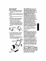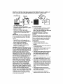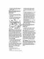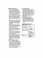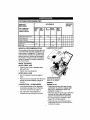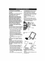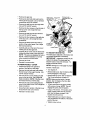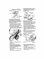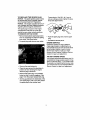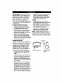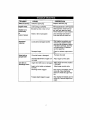
1
5.0 Horsepower
21 Inch Single Stage
Auger Propelled
SNOW THROWER
Electric Start
MODEL NO.
536.885211
Caution:
Read and follow all Safety
Rules and Operating
Instructions before first use
of this product,
SEARS, ROEBUCK
F001019M
04/27/99
AND CO., Hoffman Estates, IL 60179 U.S.A.
I
B
!
!
Table of Contents
Warranty
Safety Rules
Contents of Shipping Carton
Assembly
Operation
Maintenance
2
2
2-4
4
5
6-10
11
Service and Adjustments
Storage
Troubleshooting
Snow Repair Parts
Engine Repair Parts
Spanish(EspaSol)
Parts Ordering/Service
12-15
16
17
18-24
25-29
30-46
Back Cover
kvAv/_,1
--| Ir.,_ _ | ik"J _ir.,_l i_ivllq_| I
LIMITED
TWO-YEAR
WARRANTY
ON CRAFTSMAN
SNOW
THROWER
For two years from the date of purchase, when this Craftsman Snow Thrower is maintained, lubricated, and tuned up according to the operating and maintenance instructions in
the owner's manual, Sears will repair, free of charge, any defect in material or workmanship. If this Craftsman Snow Thrower is used for commercial or rental purposes, this warranty applies for only 90 days from the date of purchase.
This warranty does not cover the following:
Items which become worn during normal use, such as spark plugs, drive belts and
shear pins.
Repairs necessary because of operator abuse or negligence, including bent crankshafts and the failure to maintain the equipment according to the instructions contained in the owner's manual,
WARRANTY SERVICE IS AVAILABLE BY RETURNING THE CRAFTSMAN SNOW
THROWER TO THE NEAREST SEARS SERVICE CENTER/DEPARTMENT
IN THE
UNITED STATES. THIS WARRANTY APPLIES ONLY WHILE THIS PRODUCT IS IN
USE IN THE UNITED STATES.
This warranty gives you specific legal rights, and you may also have other dghts which
may vary from state to state.
Sears, Roebuck and Co., D817WA, Hoffman Estates, IL 60179
Look for this symbol to point out Important safety precautions.
ATTENTION!!! Become alertllt Your safety is involved.
CAUTION: Always turn key to OFF
position and remove key to prevent
accidental starting when setting-up,
transporting, adjusting or making repairs.
IMPORTANT: Safety standards require
operator presence controls to minimize the
risk of injury. Your snow thrower is
equipped with such controls. Do not attempt
to defeat the function of the operator
)resence control under any circumstances.
_
California
Proposition 65
WARNING:
The
engine exhaust from this product
contains chemicals known to the
State of California to cause cancer
birth defects or other reproductive
harm.
It means--
BEFORE USE
• Read the owner's manual carefully. Be
thoroughly familiar with the controls and
the proper use of the snow thrower. Know
how to stop the snow thrower and
disengage the controls quickly.
• Do not operate the snow thrower without
wearing adequate outer garments. Wear
footwear that wilt improve footing on
slippery surfaces.
• Keep the area of operation clear of all
persons, particularly small children and
pets.
• Thoroughly inspect the area where the
snow thrower is to be used and remove
all foreign objects.
• Use extension cords and receptacles as
specified by the manufacturer for all snow
throwers with electric drive motors or with
factory-installed or optional starting
motors.
• Useonlyattachments
andaccessories
approved
by the manufacturer of the
I
ing an adjustment or repair to protect your_
eyes from foreign objects that may be
snow thrower (such as electric starter kits,
thrown from the snow thrower.
etc.).
• Do not put hands or feet near or under
• Never operate the snow thrower without
rotating parts. Keep clear of the discharge
good visibility or light. Always be sure of
opening at all times.
your footing, and keep a firm hold on the
• Exercise extreme caution to avoid slipping
handles. Walk; never run.
or falling, especially when operating in
• This snow thrower is for use on sidereverse or backing up.
walks, driveways, and other ground level
•
Do not clear snow across the face of
surfaces. CAUTION: should be exemised
slopes. Excercise caultion when changing
while using on steep sloping surfaces. DO
direction on slopes. Do not attempt to
NOT USE SNOW THROWER ON
SURFACES ABOVE GROUND LEVEL
clear steep slopes.
• Never operate the snow thrower without
such as roofs of residences, garages,
porches or other such structures or
proper guards, plates, or other safety
buildings.
protective devices in place.
• Check all bolts at frequent intervals for
• Never operate the snow thrower near
proper tightness to be sure the snow
glass enclosures, automobiles, window
thrower is in safe working condition.
wells, drop-offs, and the like without
• Disengage clutch before starting the
proper adjustment of the snow discharge
engine.
angle. Keep children and pets away.
• Let engine and snow thrower adjust to
• Never operate the snow thrower at high
outdoor temperatures before starting to
transport speeds on slippery surfaces.
clear snow.
Look behind and use care when backing.
FUEL SAFETY
• Never direct discharge at bystanders or
• Handle fuel with care; it is highly flamallow anyone in front of the snow thrower
mable.
• Do not run the engine indoors, except
• Use an approved container.
when starting the engine and for trans• Check fuel supply before each use,
porting the snow thrower in or out of the
allowing space for expansion as the heat
building. Open the outside doors; exhaust
of the engine and/or sun can cause fuel to
fumes are dangerous, containing CARexpand.
BON MONOXIDE, an ODORLESS and
• Fill fuel tank outdoors with extreme care.
DEADLY GAS.
Never fill fuel tank indoors. Replace fuel
• Take all possible precautions when
tank cap securely and wipe up spilled
leaving the snow thrower unattended.
fuel.
Disengage the auger/impeller, stop
• Never remove the fuel tank cap or add
engine, and remove key.
fuel to a running or hot engine.
• Do not overload the machine capacity by
• Never store fuel or snow thrower with fuel
attempting to clear snow at too fast a rate.
in the tank inside a building where fumes
SAFE STORAGE
may reach an open flame.
• Always refer to the owner's manual
OPERATING SAFETY
instructions for important details if the
snow thrower is to be stored for an
• Never allow children or young teenagers
to operate the snow thrower. Keep them
extended period.
away while it is operating. Never allow
• Disengage power to the auger/impeller
adults to operate the snow thrower
when snow thrower is transported or not
without proper instruction.
in use.
• Do not operate this machine if you are
• Never store the snow thrower with fuel in
taking drugs or other medication which
the fuel tank inside a building where
can cause drowsiness or affect your
ignition sources are present such as water
ability to operate this machine.
and space heaters, clothes dryers, and
• Do not use this machine if you are
the like. Allow the engine to cool before
mentally or physically unable to operate
storing in any enclosure.
this machine safely.
• Always wear safety glasses or eye
shields during operation or while perform-
REPAIPJADJUSTMENTS
SAFETY
• After striking a foreign object, stop the
engine (motor). Turn key to OFF position
and remove key to prevent accidental
starting. Thoroughly inspect the
snowthrower for any damage, and repair
the damage before restarting and
operating it.
• If snow thrower should start to vibrate
abnormally, stop engine (motor) and
check immediately for the cause. Vibration is generally a warning of trouble.
• Stop the engine (motor) whenever you
leave the operating position. Also, turn
key to OFF position and remove key
before unclogging the auger/impeller
housing or discharge chute, and when
making any repairs, adjustments, or
inspections. Remove wire from spark plug
to prevent accidental starting.
• When cleaning, repairing, or inspecting,
make certain the auger/_mpeller and all
moving parts have stopped.Turn key to
OFF position and remove key to prevent
accidental starting.
• Never attempt to make any adjustments
while the engine is running except when
specifically recommended by the manufacturer.
• Maintain or replace safety and instruction
labels, as necessary.
• Run the snow thrower a few minutes after
throwing snow to prevent freeze-up of the
auger/impeller.
Z_ WARNING:
This unit is equipped with
an internal combustion engine and should
not be used on or near any unimproved forest-covered, brush-covered or grass-covered land unless the engine's exhaust system is equipped with a spark arrester meeting applicable local or state laws (if any). if a
spark arrester is used, it should be maintained in effective working order by the operator.
In the state of California the spark arrester is
required by law (Section 4442 of the California Public Resources Code). Other states
may have similar laws. Federal laws apply
on federal lands. A spark arrester/muffier is
available through your nearest Sears Authorized Service Center (See ENGINE REPAIR
PARTS section in this manual).
Contents of Parts Bag
1 - Owner's Manual (not shown)
1 - Parts Bag (not shown)
1 - 3.2 ounce container
Craftsman 2-cycle oil
1 - Electric Starter Cord
lOft.
CAUTION: Always wear safety
glasses or eye shields while assembling
snow thrower.
TOOLS REQUIRED
Chute Control Rod
FOR ASSEMBLY
\
1 - Knife to cut carton
The figure to the right shows the snow
thrower completely assembled.
References to the right or left hand side
of the snow thrower are from the viewpoint
of the operator's position behind the unit.
TO REMOVE
SNOW THROWER
FROM CARTON
• Locate and remove container of Craftsman 2-cycte oil.
• Remove the inserts positioned around the
unit and the packing material.
• Cut down two comers nearest the
handles and lay the panel down flat.
• Remove and discard bottom packaging.
• Pug snow thrower out of the carton.
TO ASSEMBLE
THROWER
THE SNOW
CHECKLIST
Before you operate your new snow thrower,
to ensure that you receive the best performance and satisfaction from this quality
product, please review the following
checklist:
• Remove wrap on upper handle and along
the side of both handles. Discard wrap.
J"
• Unfold upper handle to remove
packaging on the control panel and
discard.
All assembly instructions have been
completed.
,/
The discharge chute rotates freely.
,I
No remaining loose parts in carton.
• Loosen the tee knobs on each side of the
upper handle. See figure on this page.
• Raise the upper handle to the operating
position.
NOTE: Make sure the cables are not
caught between the upper and lower
handle.
• Check to be sure the clutch cable is not
caught in the handle. Tighten the tee
knobs.
While learning how to use your snow
thrower, pay extra attention to the following
important items:
,/,/
Make sure gas tank is filled with
40:1 ratio mixture of gasoline and oil.
./,/
Become familiar with all controls-their
location and function. Operate controls
before starting engine.
KNOW
YOUR
SNOW
THROWER
READ THIS OWNER'S MANUAL AND SAFETY RULES BEFORE OPERATING YOUR
SNOW THROWER, Compare the illustrations with your SNOW THROWER to familiarize
yourself with the location of various controls and adjustments. Save this manual for future
reference.
ElectricStart
Ignition Off
ignitionOn
.....
Oil/Fuel Mixture
Primer Button
Spark Plug
Aug
Chute ControlRod
Lower Handle
\
Chute
Starter
Button
REAR
Switch BOX
Auger Assembly
_enition Switch
Y
Auger Control Bar - Starts and stops the
auger which propels the snow thrower.
Choke Control - Used to start a cold engine
Chute Control Rod - Changes the direction of snow discharge,
Chute Deflector - Changes the distance
the snow is thrown.
Primer Button - Injects fuel directly into the
carburetor manifold for fast starts in cold
weather.
Discharge Chute - Changes the direction
the snow is thrown.
Ignition Switch Key - Must be inserted
and turned to the ON position to start the
engine.
Recoil Starter Handle - Starts the engine
manually.
Electric Starter Button - Used to start the
engine using the 120V electric starter.
Spark Plug Access Panel - Aides in spark
plug removal.
HOWTO USEYOUR
SNOWTHROWER
TOSTOPYOURSNOWTHROWER
• To stop the auger, release the auger
control bar.
NOTE: If the auger continues to creep, refer
(To Adjust Auger Control Cable paragraph on
page 12).
• To stop the engine, turn key to the OFF
position.
TO CONTROL
SNOW DISCHARGE
• Turn the chute control rod to set the
direction of the snow throwing.
• Loosen the wing knob on the chute
deflector and move the deflector to set
the distance. Move the deflector (UP) for
more distance, (DOWN) for less distance.
Then tighten the wing knob (See figure
below).
Knob
TO USE AUGER
PROPEL
/_
CAUTION: Read owner's manual
before operating machine. Never direct
discharge toward bystanders. Release the
auger control bar and stop the engine
before unclogging discharge chute or auger
housing and before leaving the machine.
BEFORE STARTING
ENGINE
WARNING:
Experience indicates that
alcohol blended fuels (called gasohol or
those using ethanol or methanol) can
attract moisture which leads to separation
and formation of acids dunng storage.
Acidic gas can damage the fuel system of
an engine while in storage. To avoid engine
problems, the fuel system should be
emptied before storage for 30 days or
longer. Start engine and let it run until fuel
lines and carburetor are empty. Use
carburetor bowl drain to empty residual
gasoline from float chamber (See figure in
Storage section, page 16). Use fresh fuel
next season. (See Storage Instructions on
page 16 for additional information).
Never use engine or carburetor cleaner
products in the fuel tank or permanent
damage may occur.
ACTION
• Squeeze the auger control bar down
against the upper handle to allow the
auger to turn.
• To propel forward, raise the handle to
allow the rubber auger blades to contact
the ground (See figure below).
Normal
Operating
Position
/
FILL GAS
NOTICE: ENGINES WHICH ARE CERTIFIED TO COMPLY WITH CALIFORNIA
AND US EPA EMISSION REGULATIONS
FOR ULGE ENGINES: Are certified to
operate on regular unleaded gasoline.
Include the following emisssion control
system(s): EM, TWC (if so equipped).
Include any user adjustable features therefore no other adustments are needed.
I
The two cycle engine used on this snow
thrower requires a mixture of gasoline and
oil for lubrication of the bearings and other
moving parts. The correct fuel mixture ratio
is 40:1 (3.2 oz. oil per gallon of gas - see
Fuel Mixture Chart). Gasoline and oil must
be preomixed in a clean gasoline container.
Always use fresh, clean, unleaded gasoline,
FUEL MIX CHART (Mixture 40:1)
U.S.
IMPERIAL
S.I. (METRIC)
OAS
O'L
/OAS
0"I OASZ
O'L
I
1Ga 3.2oz]1Ga.
Rubber Auger
Blades
GASOLINE
3.7oz.
4Lters
AND OIL MIXTURE
Mix gasoline and oil as follows:
100MLI
DO NOT FILL THE FUEL TANK WITH GASOLINE
SHAKE THE GASOLINE
CONTAINER
THAT DOES NOT HAVE OIL MIXED IN IT.
BEFORE EACH FILLING OF THE FUEL TANK.
011
(1/2 cup or 3.2 o7.)
Shake Can
1 U.S.
gallon fuel
mix
41 U.S. gallon container
_-
•
Pour 1 U.S. quart of fresh, clean,
unleaded automotive gasoline to a gallon
gasoline container.
• Add 3.2 oz of clean, high quality,
Craftsman two-cycle oil into the gasoline
container (One 3.2 ounces of oil provided).
IMPORTANT: Do not use outboard motor
oil or automobile oils, such as SAE 30 oil,
or multi-viscosity oils, such as 10W-30 or
10W-40.
• Reinstall the cap on the gasoline container and shake container vigorously so
the oil mixes with the gasoline
• Add an additional 3 U.S. quarts of
gasoline to the gallon container and
shake the container again.
WARNING: Gasoline is flammable and caution must be used when handling or storing
it. Do not fill fuel tank while snow thrower is
running, hot, or when snow thrower is in an
enclosed area. Keep away from open
flame, electrical spark, and do not smoke
while filling the fuel tank. Never fill fuel tank
completely; but fill the tank to within 1/4-1/2
inch from the top to provide space for expansion of fuel. Always fill fuel tank outdoors and use a funnel or spout to prevent
spilling. Make sure to wipe up any spilled
fuel before starting the engine. Store gasoline in a clean, approved container, and
keep the cap in place on the container.
Keep gasoline in a cool, well ventilated
place; never in the house. Never buy more
than a 30 day supply of gasoline to ensure
volatility. Gasoline is intended to be used as
a fuel for internal combustion engines;
therefore, do not use gasoline for any other
purpose. Since many children like the smell
of gasoline, keep it out of their reach because the fumes are dangerous to inhale,
as well as being explosive.
TO STOP
ENGINE
• To stop the engine, turn the key to OFF
and remove key, Keep key in a safe
place. The engine will not start without the
key, See figure on next page.
TO START ENGINE (ELECTRIC
START)
The snow thrower engine is equipped with a
120 volt AC electric starter and recoil starter.
Before starting the engine, be certain that
you have read the following information:
COLD START
• Insert the key and turn ON.
• Move the choke control to the FULL
position.
• Connect the power cord to the switch box
on the snow thrower.
• Plug the other end of the power cord into
a three hole, grounded 120 volt AC
receptacle.
• Push the primer button while covering the
vent holes as follows: (Remove finger
from primer button between primes).
Do not prime if temperature is above
50°F.
Two times if temperature is 50" F to 15°F.
Four times if temperature is below 15°F.
• Push down on the starter button until the
engine starts. Do not crank for more than
20 seconds at a time. This electric starter
is not thermally protected. Allow starter to
cool off for 10 minutes before starting
again or electric starter damaged can
Occur.
• Disconnect the power cord from the
receptacle first and then from the switch
box on the snow thrower.
• When the engine starts, release the
starter button and move choke lever to
vent holes as follows: (Remove finger
from primer button between primes).
"1/2choke"
position.
When
engine runs
smoothly, move choke lever to "No
Choke" Position.
NOTE: Allow the engine to warm up for
several minutes before blowing snow in
temperatures below 0°F.
WARM START
Do not prime if temperature is above
50 ° F.
Two times if temperature is 50 ° F to 15°F.
Four times if temperature is below 15°F.
• Pull the starter handle with a smooth
• Be sure the choke is in the OFF position and putt the starter handle unlil the
engine starts.
• Do not prime a warm engine. If the engine fails to start, follow the Cold Engine Start instructions on page 8,
Recoil
Primer
,_ Button
St rter
_ ...
vent Hope
\
r_---i/}
_
\
,_s
I
I _
/
"!i_
"_'_
leVerto
1/2choke"
poeition,
W.en
Ii
o(po ._Box
/
_' I
/
t
_=_
i i
Button
This starter is equipped to
operate on 120 volt AC household current.
Follow all instructions carefully as set forth
in the "To Slart Engine" section. When
connecting 120 volt AC power cord, always
connect the cord to the switch box on the
engine first, then plug the other end into the
household receptacle. When disconnecting
the 120 volt AC power cord, always unplug
from the household receptacle first.
TO STOP
ENGINE
• To stop the engine, turn the key to OFF
and remove key. Keep key in a safe
place. The engine will not start without
the key. See figure above.
TO START
ENGINE
(RECOIL
START)
Before starting the engine, be certain that
you have read arid understood all the
instructions on the preceding pages.
COLD START
• Insert the key and turn ON.
• Move the choke control to the FULL
position.
•
engine runs smoothly, move choke lever
toNoChoke
Position.
_
\ III;
NOTE: Allow the engine to warm up for
(;_L__._]
I_:Starter several minutes before blowing snow in
Elec_rt/er
CAUTION:
• Affer three pulls, repeat the priming and
pulling steps again.
• As engine starts warms up move choke
°%11;
' ,:!ii_i!!iii_i!iiiii==iiiiiii=,!i_/
Choke C_ntrol
/_
,!
Key,/_r"
o
o
i Jii_i_ iiiii_i
"_
r
rapid movement. Do not allow the starter
rope to snap back. Rewind smoothly
while holding the starter handle. If the
engine fires but does not start, pull the
starter handle until the engine starts.
Push the primer button while covering the
temperatures below 0°F.
WARM START
.
Do not prime a warm engine. If the englne fails to start, foBow the Cold En
gine Start instructions on this page.
Z_ CAUTI .ON: Never run engine indoors
or in enclosed, poorly ventilated areas.
Engine exhaust contains carbon monoxide,
an odorless and a deadly gas. Always stand
behind snow thrower(operator's position)
when starting engine. Do not put hands,
feet, hair or loose clothing in or near the
discharge chute deflector or auger housing
while the engine is running. The temperature of the muffler and neaby areas may
exceed 150 _ F.; avoid these areas also.
Z_ WARNING:
Objects such as gravel,
rocks or other debris, if struck by the auger,
may be thrown with sufficient force to cause
personal injury or property damage.
We recommend standard safety glasses or
Wide Vision Safety Mask for over your
glasses.
SNOW
THROWING
TIPS
WET
• This snow thrower will propel itself
forward when the handle is raised
enough to cause the auger blades to
contact the ground. The auger should
stop when auger control bar is released.
If it does not, refer to Adjust Auger
Control Cable paragraph on page 12.
PACKED
• For most efficient snow throwing, turn the
discharge chute deflector to throw snow
downwind, and slightly overlap each
swath. In light snow take up to a full cut
and in heavy snow take less than a full
cut.
SNOW
BANKS
AND DRIFTS
• In snow of greater depth than the unit,
use the jabbing technique described
above. Turn the discharge chute away
from the snow bank. More time will be
• The distance snow will be discharged can
be adjusted by moving the discharge
chute deflector. Raise the deflector for
more distance or lower the deflector for
less distance.
required to remove snow of this type than
level snow.
PRODUCT
SPECIFICATIONS
HORSE POWER:
5HP
• In windy conditions, lower the chute
deflector to direct discharged snow close
to the ground where it is less likely to
blow into unwanted areas.
DISPLACEMENT:
• Keep the area to be cleared free of
stones, toys and other foreign objects for
safety and to prevent damage to the
snow thrower.
GASOLINE
8.46 cu. in.
CAPACITY:
1.62 quart
(unleaded)
FUEL/OIL MIX RATIO: 40:1
• Do not use the auger propelling feature
when clearing gravel or crushed rock
driveways. Move the handle down to
raise the auger slightly.
• The allowable forward speed of the snow
thrower is dependent on the depth and
weight of the snow. Experience will
establish the most effective method of
using the snow thrower under different
conditions.
DRY AND AVERAGE
SNOW
• Move slowly into snow of this condition.
The greater the depth, the slower you
should go. When it appears that the wet,
packed snow is causing the auger to slow
down and the chute to clog, back off and
begin a series of short jabs into the snow.
These short back and forth, 4 to 6 inch,
jabbing motions will "belch" the snow
from the chute.
SPARK PLUG:
SNOW
• Snow up to eight inch depth can be
removed rapidly and easily by walking at
a moderate rate. For snow or drifts of a
greater depth you may find it desirable to
slow your pace to allow the discharge
chute to dispose of the snow as rapidly
as the auger receives the snow.
• Plan to have the snow discharged in the
direction the wind is blowing.
10
(3.2 oz. of aircooled engine 2
cycle oil specified
for 40:1 per 1 gal. of
gas)
Champion RCJ8Y
(Gap .030) or
Equivalent
CUSTOMER
RESPONSIBILITIES
SCHEDULE
SERVICE
RECORDS
Fill in dates as
you complete
regular service
Before
Each
Use
After
first 12
Hours
As
Needed
Before
Storage
SERVICE
DATES
Begin
r Each
Season
Tighten All Screws & Nuts
Check Spark Plug
Check Drive Belts
v,'
Lubricate Chute Control Flange
Check Fuel
p,/
v"
Drain Fuel
GENERAL
LUBRICATION
RECOMMENDATIONS
SNOW
AFTER
CHART
4,
The warranty on this snow thrower does not
cover items that have been subjected to operator abuse or negligence. To receive full
value from the warranty, the operator must
maintain the snow thrower as instructed in
this manual. The above chart is provided to
assist the operator in properly maintaining
the snow thrower.
THROWER
FIRST
USE
• Check for any loose or damaged parts
after each use.
• Tighten any loose fasteners.
AFTER
EACH
USE
• Run the machine to clear the auger of
SCOW.
Lubricate chute controlflange.
Coat flange with a clinging type
grease such as Lubdplate.
• Remove all snow and slush from the snow
thrower to prevent freezing of auger or
controls.
LUBRICATION
ENGINE
- AS REQUIRED
SPARK
• Lubricate the flange on the discharge
chute before storage. See To Remove
Top Cover instructions on page 12.
• See Lubrication Chart diagram for
lubrication points and type of lubricant.
PLUG
• Clean the spark plug and reset the gap
periodically. To service or replace spark
plug, see To Replace the Spark Plug
paragraph on page 15.
• Make sure that the spark plug is tightened
securely into the engine and the spark
plug wire is attached to the spark plug.
• If a torque wrench is available, torque
plug to 18 to 23 foot pounds.
• Clean the area around the spark plug
base before removal to prevent dirt from
entering the engine.
11
CARBURETOR
ADJUSTMENT
Thecarburetor
onthissnowthrower
isnot
adjustable.
IMPORTANT:
Ifyouthinkthecarburetor
is
notoperating
properly,
contact
your
nearest
Searsservice
center.
the cableadjustment bracket and move to
the next hole away from the top of the
bracket. See last figure on this page.
• Pull cable slack through cable adjustment
bracket and insert in the control bar. See
last figure on this page.
• Replace boot over cable adjustment
bracket.
Z_ CAUTION: Never tamper with the
engine governor which is factory set for
proper engine speed. Over speeding the
engine may increase the danger of
personal injury and will void the engine
warranty. If you think the engine governor
high speed needs adjusting, contact your
nearest Sears service center who has the
proper equipment and experience to
make any unnecessary adjustments.
TO ADJUST
THE CHUTE
• Insert "Z" hook in the auger control bar.
• Start the snow thrower and check that the
auger does not continue to turn when the
auger control bar is released.
Notchin
Flange
CRANK
Adjustments
,.,e.
ASSEMBLY
ment Bracket
If you cannot rotate the chute crank fully to the
left and to the right, you need to adjust the
chute crank. See first figure on this page.
Worm
• Remove the top cover. See To Remove
Top Cover instructions on this page.
• Loosen both 1/2" nuts on the crank
adjusting bracket using 1/2" wrenches.
Auger Control
Bar
• Swivel the crank adjusting bracket to
allow about 1/8" clearance between the
notch in the flange and the outer diameter
of the worm.
• Once this clearance is set, tighten the
nuts.
TO ADJUST
THE AUGER
Hook
CONTROL
CABLE
The auger control cable is set at the factory for
proper operation. If you need to adjust the
cable, because the control bar does not propedy engage or disengage the auger, do the
following:
Cable,-_
• Remove "Z" hook from the auger control
bar. See second figure on this page.
• Slide the boot toward the loose end of the
cable. See last figure on this page.
Cable Adjust- ,_tj
ment Brlcket_
/_Z"
_ ....Hook
_=_'/Cm_acbnl_Ad_UkSt
i
_:::Bracket
• Push the cable down through the hole in
the top of the cable adjustment bracket to
provide slack in the cable. See last figure
on this page.
TO REMOVE
TOP COVER
• Follow these steps from operator's
position.
• Remove the T-knob and fasteners on the
discharge chute.
• Remove the "Z" hook from the top hole in
t2
• Remove the gas cap.
• Remove the two bolts and nuts from the
Screws to be
removed from Top
Bolts to be
T(
removed from
front lip of the top cover. Use a flat head
screwdriver and a 3/8" wrench.
• Remove the bolt from the front right side.
Use a 5/16" and 3/8" wrench.
• Remove the four screws on the left side of
the top cover. Use a large flat head
screwdriver.
• Remove the bolt from the front left side.
Use a 5/16" and 3/8" wrench,
Cover
Chute
Shield
• Remove the four screws on the right side
of the top cover. Use a large flat head
screwdriver.
•
Remove the three screws from the top
portion of the control panel. Use a large
fiat head screwdriver.
• Carefully pull up on the rear of top cover
making sure to clear gas tank,
• Carefully lift top cover over the three bolts
holding the lower chute to the chute ring.
NOTE: This area was designed to have a
tight fit, it will be necessary to rock top
cover carefully over these bolts.
Fasteners
Lower Chute
TO ADJUST
BELT
to be
removed
from Belt
Cover
The brake pad is adjusted at the factory and
no periodic adjustment is necessary.
IMPORTANT:
Adjustment should only be
made to the brake if the brake pad has
become loose or has been removed. To
adjust proceed as follows:
• Remove top cover.
• Reinstall in reverse order.
TO REMOVE
removed from
Belt Cover
BRAKE PAD
COVER
NOTE:
• Follow these steps from operator's
position. See figureon this page.
• Remove the four bolts and nuts holding
the belt cover to the auger housing. Use
a 5/16" and 3/8" wrench.
See figure on next page for proper
location of brake pad.
• Turn engine off.
• Remove belt cover, See To Remove Belt
Cover paragraph on this page.
• Remove the top cover. See To Remove
Top Cover instructions on page 12.
• Remove the two screws holding the belt
cover to the top cover. Use a large flat
head screwdriver. NOTE: If the top cover
is already removed, omit this step.
NOTE: Make sure the belt is in proper
position. See To Replace the Drive Belt
paragraph on page 14.
• Tie the control bail to the upper handle
with a piece of stdng. NOTE: This will
engage the pulley and belt system.
• Remove the one screw holding the belt
cover to the bottom cover. Use a large flat
head screwdriver.
• Grasp the bottom portion of the belt cover
and pun down and out to remove.
• Reinstall in reverse order.
• Using a 7/16 wrench, 7/16 socket, and a
rachet loosen screw and nut on brake
pad. See first figure on page 14 for
location of screw and nut,
Adjust brake pad up or down to have a
1/8" gap between the bottom of the brake
pad and the belt.
Tighten screw and nut.
13
I
Screw and nut to Idler Pulley
be loosened
Pulley
Brake Pad
• Move belt guide into position. The belt
guide should be 3/32" from belt when belt
is engaged as shown in next figure.
• Reinstall belt cover.
TO REPLACE
THE DRIVE BELT
The drive belt on this unit is of special
construction and must be replaced with the
same type belt available at your nearest
Craftsman Service Center.
TO REPLACE
THE
AUGER
• Remove the belt cover, see To Remove
Belt Cover paragraph on page 13 and the
drive belt. See the Drive Belt Replacement paragraph on page 14.
• Remove the belt cover. See to Remove
the Belt Cover paragraph on page 13.
• Remove the auger pulley, see figure
below from the auger shaft (threads are
left hand; turn clockwise to remove). Place
a piece of wood (2x4) on the center
paddle area to secure auger to keep from
tuming.
• Move belt guide away from belt. See next
figure. Belt may come out without
loosening belt guide. Carefully press idler
pulley down to release brake pressure on
belt.
• Remove the bearing assembly from the
left frame of snow thrower by removing
the two nuts. See figure below.
_,_
_r
Guide
Brake
Roller
Housing
•
o
Spacer ,_
Belt
/
LeftFrame
• Remove belt from between brake pad
and roller.
• Remove old belt.
Auger Pulley
• Slide the auger assembly out of the
bearing assembly on the right side of the
snow thrower.
• Replace with new belt by carefully
pressing down on the idler pulley end
placing the belt between the brake pad
and roller with belt ribs down.
• Tip the auger assembly enough to allow it
to slide out of the auger housing•
• Release belt pulley.
• Attach new belt to the engine pulley and
auger pulley.
• Install the new auger assembly in reverse
order of removal.
• Make sure the belt is seated properly.
14
TO REPLACE
THE SPARK PLUG
NOTICE: This spark ignition system meets
all requirements of the Canadian Interference-Causing Equipment Regulations.
NOTICE: This engine complies with all cur-. '
rent Australian and New Zealand limitaions
regarding electromagnetic interference.
Torque plug to 18 to 20 ft. lb. If you do
not use a torque wrench, tighten the plug
firmly (See figure below).
,030
The spark plug is housed in the engine
compartment under the top cover and
cannot be seen under normal conditions.
TO REMOVE BOTTOM COVER
• Remove black plastic spark plug access
cover by squeezing the sides and pulling
cover away. See figure below.
• Push the spark plug wire onto the spark
plug.
• Reinstall the access panel.
• The spark plug and wire are now visible.
ENGINE
SERVICE
Unless the operator is fully qualified to
make engine repairs or adjustments, we
recommend that such work should be done
by technicians trained to work on snow
thrower type engines. Take your snow
thrower to your nearest Craftsman Service
Center for repair and adjustment.
ADJUST
ENGINE
SPEED
Your engine speed has been factory set. Do
not attempt to change engine speed or it may
result in personal injury, if you be[ieve that
the engine is running too fast or too slow, take
your snow throwerto your nearest Craftsman
Service Center for repair and adjustment.
• Remove the spark plug wire.
• Clean the area around the plug base to
prevent dirt from entering the engine
when the plug is removed.
• Remove the spark plug. If it is cracked,
fouled or dirty, it must be replaced. See
page 10 for the proper replacement plug.
• Set the gap between the electrodes of the
new spark plug at .030 inch. Next, install
the spark plug in the cylinder head.
15
WARNING:
Never store your snow
thrower indoors or in an enclosed, poorly
ventilated area. If gasoline remains in the
tank, fumes may reach an open flame,
spark or pilot light from a furnace, water
heater, clothes dryer, cigarette, etc.
To prevent engine damage (if snow thrower
is not used for more than 30 days) follow
the steps below.
SNOW
THROWER
STORAGE
• Thoroughly clean the snow thrower.
• Lubricate all the lubrication points. See
the Maintenance section, page 11.
• Be sure that all nuts, bolts and screws are
securely fastened. Inspect all visible
moving parts for damage, breakage and
wear. Replace if necessary.
• Touch up aU rusted or chipped paint
surfaces; sand lightly before painting.
• Cover the bare metal parts of the blower
housing and auger with rust preventative,
such as a spray lubricant.
ENGINE
on stabilizer container. Then run engine
at least 10 minutes after stabilizer is
added to allow mixture to reach carburetor. Store snow thrower in a safe place.
See Warning under STORAGE.
OTHER
• If possib|e, store your snow thrower
indoors with the gas removed and cover it
to give protection from dust and dirt,
• tf the machine must be slored outdoors,
block up the snow thrower to be sure the
entire machine is off the ground.
• Cover the snow thrower with a suitable
protective cover that does not retain
moisture. Do not use plastic or vinyl.
NOTE: A yearly checkup or tune-up at a
Craftsman Service Center is a good way of
ensuring that your snow thrower wit1provide
maximum performance for the next season.
STORAGE
Carburetor
Gasoline must be removed or treated to
prevent gum deposits from forming in the
tank, filter, hose, and carburetor during
storage. Also during storage, aJoohol
blended gasoline that uses ethanol or
methanol (sometimes called gasohol)
attracts water. It acts on the gasoline to
form acids which damage the engine.
• Remove bottom cover. See first step in
To Replace Spark Plug paragraph on
page 15.
• To remove gasoline, run the engine until
the tank is empty and the engine stops.
Then drain remaining gasoline from
carburetor by pressing upward on bowl
drain located on the bottom of carburetor.
See next figure.
Right side view of
engtne
• If you do not want to remove gasoline, a
fuel stabilizer (such as Craftsman fuel
stabilizer No. 33500) may be added to
any gasoline left in the tank to minimize
gum deposits and acids. If the tank is
almost empty, mix stabilizer with fresh
gasoline in a separate container and add
some to the tank. A_ways follow instructions on stabilizer container. Instructions
16
TROUBLE
Difficult starting
Engine stalls
CAUSE
CORRECTION
Defective spark plug
Replace defective plug
Unit running on CHOKE
Move choke lever to OFF positor
Blocked fuel line or low on fuel
Clean fuel line; check fuel supply; add fresh gasoline (gasoline/oil mixture if 2-cycle engine)
or
Loss of power
Water or dirt in fuel system
Use carburetor bowl drain to
flush and refill with fresh fuel
Excessive
vibration
Loose pads; damaged impeller
Stop engine immediately and
remove key. Tighten all bolts
and make all necessary repairs.
If vibration continues, have the
unit serviced by a Craftsman
service repairman
Damaged auger
Repair or replace auger assembly
Engine runs
erractically
Units fails to
propel itself
Unit fails to
discharge snow
Drive belt loose or damaged
Replace drive belt
Incorrect adjustment of auger control cable
Adjust auger control cable
Auger drive belt loose or damaged
Adjust auger drive belt; replace
if damaged
Adjust auger control cable
Auger control cable not adjusted
correctly
Discharge chute clogged
Foreign object lodged in auger
17
Stop engine immediately and remove key. Clean discharge
chute and inside of auger housing
Stop engine immediately and remove key. Remove object from
auger.