1
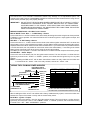
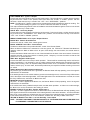
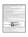
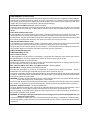
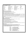
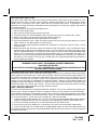
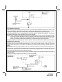
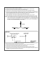
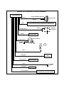
Model PRO 9171FT
Installation Manual
3 Channel Remote Car Starter
Installation Instructions
For installation in vehicles with 12 volt negative ground circuits,
gasoline engines, with automatic transmission only!
KIT CONTENTS
(1)
(2)
(2)
(1)
Remote Start Control Module
3 Button RF Keychain Transmitters
Wiring Harnesses
Parts Bag Containing
(2) Fuses
(2) Fuse Holders
(1) Control Switch
(1) Programming Switch
(1) Ring Terminal
(4) 1/2" Long Screws
(1) Pin Switch
(1) Accessory 2 Pin Connector
(1) 2 Pin Door Lock Harness
(1) Remote Start Warning Label
(1) Literature Package
The PRO-9171FT is for Automatic Transmission vehicles only! Although it is a sophisticated system, with
multiple built-in safety features, it must not be installed into vehicles with manual transmissions. Doing this can
cause serious personal injury and property damage.
IMPORTANT ! DO NOT PLUG THE SIX PIN MAIN POWER HARNESS OR THE 12 PIN INPUT / OUTPUT
HARNESS INTO THE REMOTE START CONTROL MODULE UNTIL ALL CONNECTIONS
HAVE BEEN MADE TO THE VEHICLE. AFTER SELECTING YOUR TARGET WIRES AS
DEFINED BELOW DISCONNECT THE NEGATIVE BATTERY CABLE FROM THE BATTERY
PRIOR TO MAKING ANY CONNECTIONS!
WIRING CONNECTIONS: 6 Pin Main Power Harness
RED w/ WHITE Tracer Wire : + 12 VDC Battery 1 Source
Connect this wire to a +12 VDC constant source found at the vehicles ignition switch using the 30 A fuse provided.
The Battery 1 source provides +12 volts to the PRO-9171FT module for Ignition 1 output, Ignition 2 output, and
the circuits logic.
RED Wire : + 12 VDC Battery 2 Source
Connect this wire to a + 12 VDC constant source found at the vehicles ignition switch but NOT the same wire
as the battery 1 source. Most vehicles have multiple +12 VDC battery feeds found at the vehicles ignition switch.
Separate feed wires must be used for the red and red w/white wires. If your vehicle does not provide at least two
+12 VDC feed wires, then it is possible to connect both wires to the vehicle battery. If connecting to the vehicle
battery always fuse these wires at the source using the 30 A fuses provided.
The Battery 2 source provides + 12 volts to the PRO-9171FT module for Starter output and Accessory output.
YELLOW Wire : Starter Output
Connect this wire to the starter wire from the ignition switch harness. This wire will show +12 Volts when the
ignition key is turned to the “ START or CRANK “ position, and 0 Volts when the ignition key is in any other
position.
NOTE: If installing the PRO-9171FT with an alarm that utilizes a starter cut relay, make sure the Yellow wire
is connected to the “ starter “ side of the relay contacts, and not the “ switch “ side.
WIRING THE 6 PIN MAIN POWER HARNESS
RED w/WHITE TRACE
WIRE FROM PRO 9171FT
RED WIRE
FROM PRO 9171FT
VIOLET WIRE
FROM PRO 9171FT
LT. BLUE WIRE
FROM PRO 9171FT
IGNITION SWITCH KEY POSITION
SPLICE(TYP.)
OFF
ACCESSORY
ON / RUN
START
BATT 1
BATT 2
ACC
IGN 1
IGN 2
SEE"WIRINGTHE12PINCONNECTOR"LT.BLUEWIREIFREQUIRED.
LT. GREEN WIRE
FROM PRO 9171FT
YELLOW WIRE
FROM PRO 9171FT
IGN 3
*START
*
+12 VDC IN KEY POSITION INDICATED
MAY BE +12 VDC IN KEY POSITION INDICATED
THIS CIRCUIT IS NOT ALWAYS REQUIRED FOR INSTALLATION
When installing the PRO- 9171FT into vehicles with a factory installed security system, connect the Yellow wire
between the output of the starter cut relay and the neutral safety switch.
BLUE Wire : Ignition 1 Output
Connect this wire to the ignition 1 wire from the ignition switch harness. This wire will show +12 Volts when the
ignition key is turned to the “ RUN or ON “ and the “ START or CRANK “ positions, and 0 Volts when the key
is turned to the “ OFF “ and “ ACCESSORY “ positions.
LIGHT GREEN Wire : Ignition 2 Output
Connect this wire to the ignition 2 wire from the ignition switch. This wire will show +12 Volts when the ignition
key is turned to the “ RUN or ON “ position, and in some cases, the “ START or CRANK “ position. This wire
will show 0 Volts when the key is turned to the “ OFF “ and “ ACCESSORY “ positions.
NOTE: The PRO-9171FT ignition 2 output can be programmed to remain ON while the starter is cranking. The
factory default setting for ignition 2 is to show 0 volts while the starter is cranking.
This output should be programmed at time of installation and should simulate the ignition 2 source in the vehicle
when the ignition key is used to start.
VIOLET Wire : Accessory Output
Connect this wire to the accessory wire from the ignition switch. This wire will show +12 Volts when the ignition
key is turned to the “ ACCESSORY “ and “ RUN or ON “ positions, and 0 Volts when the key is turned to the
“ OFF “ and “ START or CRANK “ positions.
WIRING CONNECTIONS: 12 Pin Input / Output Harness
BLACK Wire: Chassis Ground Source
Connect this wire to a solid, clean chassis ground source.
BLACK w/WHITE Tracer Wire: Control Switch
The Black w/ White tracer wire provides ON-OFF control of the Remote Starter.
When the Black w/ White wire is switched to a full time ground, the PRO-9171FT Remote Start Module is
operative. When the Black w/ White wire is at open circuit through the control switch, the remote starter is
disabled.
Connect the Black w/ White tracer wire to one of the terminals from the back of the control switch. Connect the
remaining terminal on the control switch to chassis ground. Always try to mount the switch so that the ON
position is in an upward direction.
GREY Wire: Negative Inhibit Input 1
Connect the GREY wire to the hood pin switch provided . This wire will be routed through the fire wall into the
engine compartment. It is necessary to use an existing grommet when passing wires through the fire wall to
prevent short circuiting. This is an important safety feature of PRO- 9171FT, and failure to use this feature can
result in serious injury. In some cases, the bracket provided may be required to facilitate mounting of the hood
pin switch.
GREY w/ BLACK Tracer Wire: Negative Inhibit Input 2
Any time the grey w/ black tracer wire is grounded, the Remote Starter will stop operating, even if the signal is
received from the transmitter.
If the brake light switch in the vehicle switches ground to the brake light circuit, connect the Grey w/ Black trace
wire to the output of the brake light switch. If the brake light switch in the vehicle switches +12 Volts, do not use
the Grey w/ Black wire; see Brown w/ Black tracer wire.
BROWN Wire: Positive Inhibit Input 1
Any time + 12 Volts is applied to the Brown wire, the Remote Starter will stop operating, even if the signal is
received from the transmitter.
If the vehicle has a factory installed hood pin switch, and that switch provides + 12 Volts to an under hood light,
the Brown wire can be connected to the existing pin switch.
BROWN w/ BLACK Tracer Wire: Positive Inhibit Input 2
Any time + 12 Volts is applied to the Brown w/ Black tracer wire, the Remote Starter will stop operating, even
if the signal is received from the transmitter. If the brake light switch in the vehicle switches + 12 Volts to the brake
light circuit, connect the Brown w/ Black trace wire to the output of the brake light switch. If the brake light switch
in the vehicle switches ground, do not use the Brown w/ Black wire; see Grey w/ Black tracer wire.
YELLOW w/ BLACK Tracer Wire: + 12 Volt Alarm By - Pass Output
NOTE: YOU MUST DISCONNECT THE IGNITION INPUT OF THE ALARM FROM ANY OTHER WIRE THAT
IT IS PRESENTLY CONNECTED TO IN THE VEHICLE.
3
This wire provides a 500 mA + 12 Volt transistorized output when the ignition key is turned to the “ON” position, and 0
Volts when the ignition key is “OFF” and when the vehicle is running under the control of the remote starter.
This wire should be connected to the ignition input of the alarm system.
The Yellow w/ Black wire output will allow you to remote start the vehicle while leaving the alarm armed.
(2) WHITE Wires: Parking Light Flasher
These wires are the COMMON and NORMALLY OPEN contacts of the on-board parking lamp relay.
If the vehicle's parking lights are a +12 volt switched system, connect (1) of the White wires to a fused (15A max.) +12
volt battery source, and connect the second White wire to the vehicle's parking light wire.
If the vehicle's parking lights are a chassis ground switched system, connect (1) of the White wires to a chassis ground
source, and connect the second White wire to the vehicle's parking light wire.
LIGHT BLUE Wire: Ignition 3 / Shock Disable Output
This is a 500 mA transistorized ground output, and an external relay will be required in all cases that this output is needed.
NOTE: This Light Blue wire is energized 3 seconds before the PRO- 9171FT starts the engine. This wire remains
energized for 4 seconds after engine shut down.
The Light Blue output serves the following functions.
A. Shock Sensor Override: If the alarm is connected to a shock sensor, then the vibration caused by remote starting
the vehicle may trigger the alarm. If this is the case, connect the Light blue wire to terminal 86 of an external relay. Connect
terminal 85 of the relay to a fused + 12 Volt battery source. Cut the trigger wire from the shock sensor, and connect one
side of the cut wire to terminal 30 of the relay. Connect the other side of the cut wire to terminal 87a of the relay. Just
before the remote starter is activated, the relay contacts will open, and the shock sensor will not trigger the alarm. Four
seconds after the remote start unit shut down the shock sensor will be operational.
B. Ignition 3 Output: Some newer vehicles use a third ignition wire, which is necessary to keep the engine running. If
this is the case, connect the Light Blue wire to terminal 86 of an external relay. Connect terminals 85 and 30 together
to a + 12 Volt battery source that is fused for a minimum 25 A rating. Connect terminal 87 of the external relay to the third
ignition wire in the vehicle.
C. G.M. VATS Key Override: If the vehicle has the General Motors VATS system installed, you will need to by-pass the
starter cut portion of the VATS system. To do this;
1. Measure the resistance of the ignition key, and get a resistor which value is within 5% of the key value.
2. Locate the pair of VATS wires in the vehicle, usually a pair of thin gauge wires running from the ignition switch to
the VAT 1 Control Unit.
VATS WIRE #2
MATCHING RESISTOR
87
VATS WIRE #1 (CUT)
TOWARDS IGNITION SWITCH
87a
86
VATS WIRE #1 (CUT)
TOWARDS VATS MODULE
30
85
TO FUSED +12 VDC
BATTERY SOURCE
LIGHT BLUE IGN. 3 WIRE FROM REMOTE START MODULE
NOTE: These wires are typically White w/ Black tracer and Violet w/ Yellow tracer, however in late model Cadillacs, they
are run through an Orange sleeve, and are either both Black, both Yellow, or both White wires.
Consult the factory service manual for additional information.
3. Connect the Light Blue wire from the Remote Starter to terminal 86 of an external relay. Connect terminal 85 of the
relay to a fused + 12 Volt battery source.
4. Cut (1) of the VATS wires, and connect the ignition switch side of the cut wire to terminal 87a of the relay. Connect
the other side of the cut wire to terminal 30 of the relay.
5. Connect the resistor from terminal 87 of the relay to the second VATS wire.
4
DARK GREEN Wire: Tach Sensor Input
This wire will continually monitor the tach rate while the engine is running under power supplied by the Remote Starter.
This wire will be routed through the fire wall into the engine compartment. It is necessary to use an existing grommet
when passing wires through the fire wall to prevent short circuiting. Connect this wire to the existing tach wire, or the
negative side of the ignition coil in the vehicle. (See RF Program Settings).
Red and Green 2 Pin White Connector : Door Lock Outputs
These wires will provide either a pulsed ground output to the factory door lock control relay, or a pulsed +12 volt output
to the factory door lock control relay. In either case, the maximum current draw through these outputs must not exceed
300 mA.
3 Wire Ground Switched door locks
In this application, the red wire provides a ground pulse or the pulsed ground lock output. Connect the red wire to the
wire that provides a low current ground signal from the factory door switch to the factory door lock control relay.
In this application, the green wire provides a pulse ground unlock output. Connect the green wire to the wire that provides
a low current ground signal from the factory door switch to the factory door unlock control relay.
3 Wire Positive Switched Door Locks
In this application, the red wire provides a pulsed +12 volt unlock output. Connect the red wire to the wire that provides
a low current positive signal from the factory door switch to the factory door unlock control relay.
The green wire provides a positive pulsed +12 volt lock output. Connect the green wire to the wire that provides a low
current positive signal from the factory door switch to the factory door lock control relay.
4 Wire Polarity Reversal and
5 Wire Alternating 12 Volt
Door Lock Control Circuits
In these applications, the AS 9159 Door Lock Interface ( or equivalent 30 A automotive relays) must be used. Refer to
the AUDIOVOX Door Lock Wiring Supplement for proper connection to these types of circuits.
2 Pin Blue Connector : Programming Switch
Route the grey and black wires in the 2 pin connector from the programming switch to the control module and plug it
into the mating blue connector on the side of the module.
Blue and Green w/Black Trace Wires - 2 Pin White Connector : Accessory Outputs
Dark Blue Wire : Delayed 300 mA Pulsed Output/Channel 2
The dark blue wire pulses to ground via an independent RF channel from the keychain transmitter. This is a
transistorized, low current output, and should only be used to drive an external relay coil.
This output is activated by the same transmitter button that is used to activate the remote start function (factory default
is button 2). Press and hold button 2 to activate this trunk release output, or press and release button 2 two times within
2 seconds to activate the remote starter.
WARNING: Connecting the dark blue wire to the high current switched output of the trunk release circuits and some
remote start trigger inputs, will damage the control module.
Connect the dark blue wire to terminal 86 of the AS-9256 relay (or equivalent 30 A automotive relay), connect terminal
85 to a fused +12 volt source and wire the remaining relay contacts to perform the selected function of channel 2.
Dark Green w/Black Trace Wire : Latching Output/Channel 3
The green w/black trace wire latches to ground via an independent RF channel from the keychain transmitter. This is
a transistorized, low current (300 mA) output, and should only be used to drive an external relay coil.
This wire provides an immediate ground signal, and stays at ground for up to 8 seconds as long as the button(s) on
the keychain transmitter remain pressed.
WARNING ! Connecting the dark green w/black trace wire to any high current switched output (300 mA max.) will
damage the control module.
Connect the dark green w/black trace wire to terminal 86 of the AS-9256 relay (or equivalent 30 A automotive relay),
connect terminal 85 to a fused +12 volt source and wire the remaining relay contacts to perform the selected function
of channel 3.
5
1. RF Programmable Features:
Feature Selection
First
Second
Third
Fourth
Fifth
Sixth
Seventh
Eighth
1 Flash
1 Second Door Locks
10 Minute Run Time
Park Lights Steady On
(No Function)
(No Function)
Ignition 2 Off During Crank
Diagnostics Off
(No Function)
2 Flashes
3.5 Second Door Locks
15 Minute Run Time
Park Lights Flash
Tach Operation
(No Function)
Ignition 2 On During Crank
Diagnostics On
(No Function)
Default
1 Second
10 Minute
Steady
Tach
-----------Off During Crank
Off
-------------
To program these selectable features:
1.
2.
3.
4.
5.
6.
Start with the programming switch in the OFF position.
Turn the ignition key to the ON position.
Flip the program switch ON - OFF - ON - OFF - ON - then OFF.
Immediately turn the ignition key OFF, then back to ON.
Flip the program switch ON - OFF - ON - then OFF.
Use button 1 on the transmitter to advance to the feature that you want to change. EXAMPLE - If you need to change
programmable feature number 3, press and release button 1 on the transmitter 3 times in succession. The parking
lights will flash 3 times confirming that selected feature 3 can now be programmed.
7. Use button 2 on the transmitter to change the selection of the programmable feature. If you are not sure what the
setting for any feature is, press button 2 one time, the parking lights will flash once or twice indicating the features
setting.
Note: Once you enter the feature programming mode, do not allow more that 15 seconds to pass between steps, or
the programming will be terminated.
2. Programming Tach Rate:
The PRO- 9171FT Remote Car Starter will learn the tach rate of the vehicle. To learn tach;
1. Start with the programming switch in the OFF position.
2. Turn the ignition key to the ON position.
3. Flip the program switch ON - OFF - ON - OFF - ON - then OFF.
4. Immediately turn the ignition key OFF.
5. Flip the program switch ON, then start the vehicle using the ignition key.
6. When the unit senses the tach signal, the parking lights will begin to flash.
7. Flip the program switch OFF. The parking lights will turn on for 3 seconds to indicate that the tach signal is stored
and the unit is now out of the program mode.
3. Diagnostics:
1. Be sure that programmable feature number 7 is set to the "Diagnostics On" mode.
2. First flip the program switch on, then turn the ignition key to the ON position.
3. The lights will flash, and number of flashes will indicate the reason for shutdown on the last remote start
attempt. The indications are as follows.
1 Flash
2 Flashes
10 or 15 Minute Run Timer Expired
Low or No Tach Signal (RPM)
3 Flashes
4 Flashes
Positive Shutdown Wire Activated
Control Switch Moved to Off Position
5 Flashes
6 Flashes
R.F. Shutdown Signal Received
High RPM Signal Received
7 Flashes
Negative Shutdown Wire Activated
6
NEUTRAL START SAFETY TEST:
The intent of the neutral start switch is to prevent the vehicle from starting while the gear selector is in any
position other than Park, or Neutral. When installing a Remote Start Device, it is imperative that the Yellow
Starter wire be connected to the ignition switch side of the Neutral Start Switch. Consideration for the
placement of a starter inhibit relay is important as well, and should be connected to the ignition switch side of
the Yellow Start Wire.
To test the integrity of the Neutral Start Safety Circuit:
1. Set the vehicle parking brake.
2. Block the drive wheels to prevent vehicle movement.
3. Temporarily disconnect the Brown/Black positive shut down wire from the vehicle's brake switch.
4. Sitting in the vehicle, start the engine using the vehicle's ignition key.
5. Step on the brake pedal and shift the gear selector into reverse.
6. Allow the transmission to shift. When you feel the engine pull, do not move the gear selector just turn the
ignition switch off. DO NOT attempt to remove the key.
7. Keeping the brake pedal depressed, activate the RF transmitter in an attempt to start the vehicle. The car
should not start.
8. Repeat the above test this time move the gear selector to the drive position. If the unit attempts to start,
failing this test, recheck your Yellow Wire's connection. This wire must be connected to the ignition switch
side of the Neutral Start Switch. If the vehicle you are working on does not have an Electrical Neutral Safety
Switch, it will be necessary to reconfigure the Remote Starts Wiring to accommodate this vehicle. The
information concerning the Mechanical Neutral Safety Switch provided below will help you to determine if
the vehicle you are working on has this type of safety switch and will provide alternate wiring methods to
accommodate this situation.
CAUTION!
REMEMBER TO RECONNECT THE BROWN/BLACK WIRE TEMPORARILY
DISCONNECTED IN STEP 3
DO NOT RELEASE THIS VEHICLE TO THE CONSUMER UNTIL YOU CONFIRM THE OPERATION OF THE
NEUTRAL SAFETY START FEATURE.
MECHANICAL NEUTRAL SAFETY SWITCH CONSIDERATIONS:
Mechanical neutral safety switch configurations differ slightly in that they do not offer the same level of safety
when installing a remote start device. Often when the ignition switch is turned off while the gear selector is in
any position other than park or neutral, the mechanical function will not allow the key to be turned to the start
position or be removed from the ignition cylinder. This configuration prevents mechanical operation while the
vehicle is in gear but offers no consideration for electrical operation. Because of this potential problem, this
installation requires the additional connection of a safety wire from the remote start device to the vehicle Park/
Neutral ECM Input or the vehicle key in sensor. This connection will prevent remote start operation if the key
is left in the ignition switch regardless of the gear selectors position.
PARK / NEUTRAL ECM INPUT:
The Park / Neutral ECM input is the preferred method of installation. This not only maintains the integrity of the
factory circuit, it is also the easiest to install, providing the vehicle you are working on has this ECM input.
The installation required for this application (shown below), indicates the slight reconfiguration of the control
switch wiring and the addition of a 4000 series diode. Shown is a typical GM Park/Neutral ECM input circuit.
To connect the Audiovox remote start unit to the GM Park / Neutral ECM input:
1. Locate the Orange / Black reference wire in the" C2" connector found at the ECM in GM B Body vehicles or,
locate the equivalent reference wire in the vehicle you are installing the Audiovox Remote Start Unit in.
2. Connect the Cathode, (Striped) end, of a 4000 series diode to this reference wire.
3. Connect the Anode, (Non Striped) end, of the diode to one side of the Remote Start enable switch.
4. Connect the other side of the enable switch to the Black/White enable input wire of the Remote Start unit.
The reference diagram below shows a typical GM B Body ECM reference wire and how it is to be connected to
the Remote Start Unit.
7
128-5404
Sht. 7 of 12
KEY IN SENSOR CIRCUITS:
If the vehicle you are working on does not have or you cannot locate the ECM reference wire, there are two
alternatives available. Although not preferred, the vehicle Key In Sensor may be reconfigured to allow a margin
of safety and will prevent the vehicle with a Mechanical Neutral Start Switch from starting in gear.
AUDIOVOX ADVISES THAT YOU MAINTAIN THE FACTORY CIRCUIT WHENEVER POSSIBLE. The following
two circuits may be used only if the above circuit is not available.
NOTE: When completing an installation using either of the following key in sensor circuits, if the operator inserts
the ignition key while the vehicle is running under the control of the Remote Start, the vehicle will shut
down. This must be explained to the operator as it is in contrast to the normal operation of a vehicle
utilizing an electrical neutral start switch and is inconsistent with the operators manual.
Additional information concerning Key In Sensor methods 1 & 2 are listed below and should be reviewed before
considering either alternative.
Method 1 will allow the safety required for the remote start unit and prevent the vehicle from starting while in
any gear other than Park or Neutral while the key is in the ignition cylinder however, if the key is left in the
ignition switch and the door is left opened, the added relay will be energized causing a 150mA drain on the
battery.
Method 2 will allow the safety required for the remote start unit and prevent the vehicle from starting while in
any gear other than Park or Neutral while the key is in the ignition cylinder however, the original factory key in
chime module will not alert the owner that the key has been left in the ignition switch. In addition, this may also
effect other warning tones such as the light on reminder.
These situations should be carefully considered before altering the vehicle's wiring and must be fully explained
to the consumer.
These circuits may be used only if the above circuit is not available.
METHOD 1
8
128-5404
Sht. 8 of 12
To connect to the key in sensor as shown in method 1:
A. Locate the control wire that connects the drivers door pin switch to the key in sensor switch.
B. Cut this wire and connect the ignition cylinder side to chassis ground.
C. Locate the key in sensor switch wire that connects the chime module to the ignition cylinder .
D. Cut this wire and connect the ignition cylinder side to terminal 30 of a P&B VF45F11 or equivalent relay.
E. Connect the cathode (striped) side of a 4002 series diode to this same wire, and connect the (non striped)
side to the negative shut down safety wire (Gray / Black) of the Audiovox Remote Start Unit.
F. Connect terminal 86 of the relay to a fused +12 volt constant battery source.
G. Connect terminal 87 of the relay to the Chime Module side of the previously cut wire in step D.
H. Connect terminal 85 of the relay to the Drivers Door side of the pin switch wire previously cut in step B.
NOTE: A second 4002 series diode may be required to maintain the integrity of the hood open, shut down
circuit. If this is the case, it must be installed as shown in the diagram above. The anode (Non Striped)
side must be connected to the Gray/Black wire of the Remote Start Unit. The cathode (Striped) side
must be connected to the hood pin switch. If the hood pin switch is also used for an alarm trigger input,
be certain to use a dual diode assembly as shown below .
METHOD 2
To connect to the key in sensor circuit as shown for method 2:
A. Locate the control wire that connects the drivers door pin switch to the key in sensor switch.
B. Cut this wire and connect the ignition cylinder side to chassis ground.
C. Locate the key in sensor switch wire that connects the chime module to the ignition cylinder .
D. Cut this wire and connect the ignition cylinder side to the Remote Start Negative Safety Shut down Wire
Gray/Black, using a 4002 series diode as shown above.
9
NOTE: A second 4002 series diode may be required to maintain the integrity of the hood open, shut down
circuit. If this is the case, it must be installed as shown in the diagram above. The anode (Non Striped)
side must be connected to the Gray/Black wire of the Remote Start Unit. The cathode (Striped) side
must be connected to the hood pin switch. If the hood pin switch is also used for an alarm trigger input,
be certain to use a dual diode assembly as shown in the diagram above.
AFTER THE CONNECTION OF THE NEUTRAL START SAFETY WIRE AS INDICATED IN ANY OF THE
PREVIOUS ALTERNATE CONFIGURATIONS, THIS CIRCUIT MUST BE TESTED FOR OPERATION.
Retest by following the steps outlined in the NEUTRAL START SAFETY TEST shown in this manual.
COMPLETING THE INSTALLATION:
1. Select a desired mounting location for the program switch and the control switch. The switches may be
mounted in or below the dash by drilling a 1/4" dia. hole. Be sure to check behind the dash for adequate
clearance for the body of the switch, and to confirm that the drill will not damage any existing components
as it passes through the dash. Always try to mount these switches so that when the switch is moved to
the upward position it is on (closed to ground). Always place the red switch handle cover, (provided), on the
control switch so it will be easy for your customer to distinguish the control switch from the program switch.
2. Mount the control module behind the dash using cable ties or sheet metal screws.
3. Securely tape and tie all wiring up and away from all hot or moving objects that may come in contact with
under the dash area.
CAUTION: Particularly avoid the area around the steering shaft and steering column, as wires can wrap around
these mechanisms and impede the vehicles ability to be properly controlled.
4. Apply the Caution label included in the kit to an area in the engine compartment that is clearly visible when
the hood is opened. Make sure the surface is clean before applying the label.
5. Replace all panels that were removed during installation, and re-test the system.
6. Explain all activated features of the remote starter to the customer.
10
WIRING THE 12 PIN INPUT / OUTPUT HARNESS
12 PIN CONNECTOR
EXISTING PARKING LAMP WIRE
WHITE
PARKING LAMP
SPLICE
WHITE
TO +12 VOLT BATTERY FOR POSITIVE SWITCHED PARKING LIGHTS
TO CHASSIS GROUND FOR NEGATIVE SWITCHED PARKING LIGHTS
SPLICE
BROWN w/BLACK
BROWN
BLACK w/WHITE
EXISTING
BRAKE SWITCH
POSITIVE INHIBIT 1
CONTROL SWITCH
CHASSIS
GROUND
HOOD
PINSWITCH
GREY
IGNITION3
OR
SHOCKBY-PASS
LIGHT BLUE
GREY w/BLACK
NEGATIVE INHIBIT 2
BLACK
DARKGREEN
TO CHASSIS
GROUND
TACH
YELLOW w/BLACK
TO ALARM'S IGNITION INPUT(YELLOW WIRE OF AUDIOVOX ALARMS)
11
© 1998 Audiovox Corporation, Hauppauge, NY 11788
128-5404