1
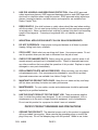
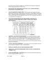
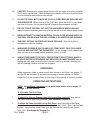
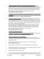
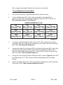
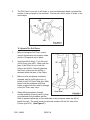
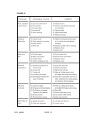
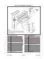
DRILL PRESS
10” BENCH/12 SPEED
ASSEMBLY AND
OPERATING INFORMATION
3491 Mission Oaks Blvd., Camarillo, CA 93011
Visit our Web site at http://www.harborfreight.com
Copyright © 2001 by Harbor Freight Tools. All rights reserved. No portion of this
manual or any artwork contained herein may be reproduced in any shape or form
without the express written consent of Harbor Freight Tools.
For technical questions please call 1-800-444-3353
SPECIFICATIONS
ITEM
DESCRIPTION
Net Weight
132 Lbs.
Overall Height
33 - 1/4”
Column Length (Head to Base)
18 - 1/4”
Table Size
7 - 7/16” x 7 - 3/4”
Speeds (12)
250, 340, 390, 510, 600, 650, 990, 1550,
1620, 1900, 2620, 3100
Swing Diameter
10”
Motor Electrical Specifications
120V/60hz 1/2hp motor-1700rpm single phase
Load Amps: 3.5 No Load Amps: 1.6
Spindle Stroke
2 - 3/8”
Spindle Taper
MT-2
Column Diameter
2.355”
Chuck Size
7/64” - 5/8” (3 - 16MM)
SAVE THIS MANUAL
You will need the manual for the safety warnings and precautions, assembly
instructions, operating and maintenance procedures, parts list and diagram. Keep
your invoice with this manual. Write the invoice number on the inside of the front
cover. Keep the manual and invoice in a safe and dry place for future reference.
GENERAL SAFETY WARNINGS AND PRECAUTIONS
1.
KEEP WORK AREA CLEAN AND DRY. Cluttered, damp or wet work areas invite
injuries.
2.
KEEP CHILDREN AWAY FROM WORK AREA. Do not allow children to handle this
product.
3.
STORE IDLE EQUIPMENT. When not in use, tools and equipment should be stored
in a dry location to inhibit rust. Always lock up tools and equipment and keep out of
reach of children.
4.
DO NOT USE THIS PRODUCT IF UNDER THE INFLUENCE OF ALCOHOL OR
DRUGS. Read warning labels on prescriptions to determine if your judgment or
reflexes are impaired while taking drugs. If there is any doubt, do not attempt to use
this product.
SKU 44836
PAGE 2
5.
USE EYE, HEARING, AND BREATHING PROTECTION. Wear ANSI approved
safety impact eye glasses, ANSI approved hearing protection, and ANSI approved
dust mask or respirator when using this product. ANSI approved safety impact eye
glasses, hearing protection, and dust masks and respirators are available from
Harbor Freight Tools.
6.
DRESS SAFELY. Non-skid footwear or safety shoes should be used when working
with this product. Do not wear loose clothing or jewelry as they can become caught
in moving parts. Wear a protective hair covering to prevent long hair from becoming
caught in moving parts. If wearing a long-sleeve shirt, roll sleeves up above
elbows.
7.
INDUSTRIAL APPLICATIONS MUST FOLLOW OSHA REQUIREMENTS.
8.
DO NOT OVERREACH. Keep proper footing and balance at all times to prevent
tripping, falling, back injury, etcetera.
9.
STAY ALERT. Watch what you are doing at all times. Use common sense. Do not
use this product when you are tired or distracted from the job at hand.
10.
CHECK FOR DAMAGED PARTS. Before using this product, carefully check it will
operate properly and perform its intended function. Check for damaged parts and
any other conditions that may affect the operation of this product. Replace or repair
damaged or worn parts immediately.
11.
REPLACEMENT PARTS AND ACCESSORIES. When servicing, use only identical replacement parts. Only use accessories intended for use with this product.
Approved accessories are available from Harbor Freight Tools.
12.
MAINTAIN THIS PRODUCT WITH CARE. Keep this tool clean and dry, and keep
drill bits clean and sharp for better and safer performance.
13.
MAINTENANCE: For your safety, service and maintenance should be performed
regularly by a qualified technician.
14.
USE THE RIGHT PRODUCT FOR THE RIGHT JOB. There are certain applications for which this product was designed. Do not use small equipment, tools or
attachments to do the work of larger industrial equipment, tools or attachments.
Do not use this product for a purpose for which it was not intended.
PECIFIC PRODUCT WARNINGS AND PRECAUTIONS
1.
GROUND THIS PRODUCT. The electrical power cord for this product is equipped
with a grounded 3-prong plug. Never remove the grounding prong or modify the
plug in any way. Do not use adapter plugs with this product. When in use, make
SKU 44836
PAGE 3
sure this product is always plugged into a grounded 3-hole electrical receptacle
with an appropriate breaker switch in-line.
2.
MAKE SURE THE POWER SWITCH IS IN THE “OFF” POSITION BEFORE
PLUGGING IN THE POWER CORD.
3.
DO NOT ABUSE THE POWER CORD. Do not use the cord to pull the 3-prong
plug from a power outlet. Keep cord away from heat, oil, sharp edges, and moving
parts. Replace damaged cord immediately. Route the power cord safely. Protect it
from being damaged by other equipment in the shop. Do not route the cord where it
can be walked on or tripped over.
4.
IF YOU USE AN EXTENSION CORD, MAKE SURE TO USE ONLY UL
APPROVED CORDS HAVING THE CORRECT GAUGE AND LENGTH.
(SEE FIGURE A.)
FIGURE A
5.
MAINTAIN A SAFE WORK ENVIRONMENT. Do not use this product in or near
damp or wet areas. Do not expose this product to rain. Keep work area well lit.
Use this product in a well ventilated area. Do not operate this product in the presence of flammable liquids, gases, or dust. To avoid accidental electric shock, do
not let your body come in contact with grounded surfaces such as pipes, radiators,
ranges and refrigerators.
6.
DO NOT FORCE THE EQUIPMENT. This product will do the work better and safer
at the speed and capacity for which it was designed.
7.
KEEP ALL GUARDS IN PLACE AND IN WORKING ORDER.
8.
REMOVE ALL ADJUSTING WRENCHES FROM THE DRILL PRESS BEFORE
TURNING IT ON.
9.
AVOID UNINTENTIONAL STARTING. Make sure you are prepared to begin work
before turning the START switch on.
SKU 44836
PAGE 4
10.
CAUTION: Some woods contain preservatives such as copper chromium arsenate
(CCA) which can be toxic. When drilling these materials extra care should be taken
to avoid inhalation and minimize skin contact.
11.
ALLOW THE DRILL BIT TO SPIN UP TO FULL SPEED BEFORE DRILLING INTO
THE WORKPIECE. When turning off the Drill Press, allow the drill bit to spin down
and stop on its own. Do not press the drill bit against the workpiece to stop it.
12.
DO NOT FORCE THE DRILL BIT INTO THE WORKPIECE WHEN DRILLING.
Apply moderate downward pressure, allowing the drill bit to cut without being forced.
13.
NEVER ATTEMPT TO REMOVE MATERIAL STUCK IN THE MOVING PARTS OF
THE DRILL PRESS WHILE THE DRILL PRESS IS PLUGGED IN AND RUNNING.
14.
THE DRILL BIT WILL BECOME HOT WHILE DRILLING. Allow the drill bit to
completely cool before touching.
15.
WHENEVER POSSIBLE, USE CLAMPS OR OTHER SAFE, PRACTICAL WAYS
TO HOLD AND SUPPORT THE WORKPIECE. Do not attempt to drill material that
does not have a flat surface, unless a suitable support is used.
16.
ALWAYS DISCONNECT THE DRILL PRESS FROM ITS ELECTRICAL SUPPLY
SOURCE BEFORE PERFORMING ANY SERVICES OR MAINTENANCE such as
leaving the work area, moving the tool from one location to another, changing the
drill bit, cleaning sawdust from the unit, etcetera.
UNPACKING
When unpacking, check to make sure all parts shown on the Parts Lists (pages 13
through 16) are included. If any parts are missing or broken, please call Harbor
Freight Tools at the number shown on the cover of this manual as soon as possible.
OPERATING INSTRUCTIONS
NOTE: For additional references to the parts listed below, refer to pages 13
through 16 of this manual.
To Assemble The Drill Press:
1.
To attach the Column Support (part #3A) to the Base (part #4A), use the four
Hex Head Screws (part #5A) provided. (See Assembly Diagram A.)
2.
To attach the Table (part #9A) to the Drill Press, insert the collar of the Table
(located on the underneath) into the Table Support (part #10A). Then, lock the Table
in place, using the Hex Head Screw (part 8A) and the Hex Head Socket Screw
(part 17A). (See Assembly Diagram A.)
SKU 44836
PAGE 5
3.
To attach the Head Assembly (part #1B) to the Column (part #1A), loosen
the Hex Screws (part #13B) to ensure the Screws do not protrude internally in the
Column (part #1A), as this would prevent the Head Assembly from sliding downward
fully onto the Column. With assistance raise the Head Assembly and slide it fully
onto the Column, aligning the Head Assembly with the Base (part #4A). Lock the
Head Assembly in place by tightening the Hex Screws (part #13B).
(See Assembly Diagrams A and B.)
4.
To attach the Knobs (part #16B) and Rods (part #17B) onto the Hub Assembly
(part #18B), screw the three Knobs onto the three Rods. Then, screw the three
Rods into the Hub Assembly. (See Assembly Diagram B.)
5.
To attach the Chuck (part #8C), attach the Table Crank (part #6A) to the Table
Support (part #10A). Raise the Table (part #9A) up the Column (part #1A) to within
6” of the Tube Quill (part #10C). Open the jaws of the Chuck (part #8C), using the
Key Chuck (part #9C). Place a piece of scrap wood on the Table to protect the nose
of the Chuck. Insert the Spindle Shaft (part #7C)-which includes Drill Chuck Arbor
(part 30C), firmly into the end of the Chuck.
Insert the other end of the Spindle Shaft into the Tube Quill, and turn the Spindle
Shaft until the prong on the Spindle Shaft aligns with the slot in the Tube Quill.
Lower the Spindle Shaft, and press the nose of the Chuck firmly down onto the
scrap wood on the Table until the Chuck is securely seated.
(See Assembly Diagrams A and C.)
To Attach The Remaining Handle:
1.
1.
To attach the Knob (part #1C) to the Pulley Guard (part #5C), use the Pan Head
Screw (part #2C) provided. (See Assembly Diagram C.)
To Mount The Drill Press On A Workbench:
When in use, the Drill Press should be securely mounted to a flat, level, sturdy
workbench capable of supporting the weight of the Drill Press, accessories, and the
material being drilled.
2.
The Base (part #4A) of the Drill Press features four 1/2” mounting holes.
(See Assembly Diagram A.)
3.
With assistance, set the Drill Press in the desired position on the workbench.
4.
Using the mounting holes on the Base (part #4A) as a template, mark the 1/2” holes
to be drilled through the top of the workbench.
5.
With assistance, set the Drill Press aside.
6.
Use a 1/2” drill bit to drill the four holes through the workbench. Reposition the Drill
Press on the workbench and secure the Drill Press to the workbench, using four 1/2”
SKU 44836
PAGE 6
REV 04/04
Bolts of appropriate length, Washers and Locknuts (not provided).
To Install/Reposition The Drive Belts:
1.
The Drill Press features 12 speed selections from which to choose.
2.
The two V-Belts (parts #21C, 26C), when positioned on the three Pulleys
(parts #3C, 28C, 19C), will determine the speed at which the Drill Press will run.
(See Assembly Diagram C and Figure B.)
SPINDLE SPEED IN R. R. M.
FIGURE B
3.
To install or reposition the two V-Belts (parts #21C, 26C), release the two Motor
Adjusting Knobs (part #12B) which are located on both sides of the Head Assembly
(part #1B). (See Assembly Diagram B.)
4.
Lubricate the Idler Pivot Shaft (part #29C) and Center Pulley (part #28C) with a light
grease, and install the Pivot Shaft in the hole located between the Motor Pulley
(part #3C) and Spindle Pulley (part #19C). Then, insert the Center Pulley onto the
Idler Pivot Shaft. (See Assembly Diagram C.)
5.
Consult the Chart inside the Pulley Guard (part #5C) or refer to Figure B, and install
the V-Belts (parts #21C, 26C) in the positions corresponding to the drill speed
desired.
6.
Secure the V-Belts (parts #21C, 26C) in position by locking the two Motor Adjusting
Knobs (part #12B). (See Assembly Diagrams B and C.)
SKU 44836
PAGE 7
REV 12/06
To Obtain The Proper Cutting Speeds:
1.
Factors which determine the best speed to use in the Drill Press are:
A. The kind of material being drilled.
B. The size of the hole.
C. The quality of cut desired.
2.
Generally, in soft material the speed should be higher than for hard materials. The
following guide indicates the proper Drill Press speed (RPM) for a given drill bit size
and the material being drilled. (See Figure C.)
FIGURE C
SKU 44836
PAGE 8
To Adjust The Table:
1.
The Table (part #9A) may be adjusted in 4 directions.
2.
To raise or lower the Table, release the Table Clamp (part #11A), and turn the
Crank (part #6A) clockwise to raise the Table and counterclockwise to lower the
Table. When the desired height of the Table has been reached, secure the Table in
place by locking the Table Clamp.
(See Assembly Diagram A and Figure D.)
3.
To move the Table to the right or left, release the Table Clamp (part #11A) and
move the Table left or right to the desired position. Once the desired position
has been set, secure the Table in place by locking the Table Clamp. (See Figure D.)
To Adjust The Spindle Depth:
1.
Located on the Hub Pinion (part #18B) is a Depth Lock Screw (part #14B) and a
Depth Stop Ring w/Scale (part #15B), with depth settings in both inches and metric
units. (See Assembly Diagram B and Figure E.)
2.
To set a drilling depth, insert and secure a drill bit in the Chuck (part #8C).
3.
Lower the drill bit (with the power OFF) until it contacts the material to be drilled, and
hold in that position.
4.
Loosen the Depth Lock Screw (part 14B), and turn the Depth Stop Ring w/Scale
(part #15B) so that the measurement for the depth of hole desired is in line the
Stop Pin (part #19B). Lock the Depth Stop Ring w/Scale in position, using the
Depth Lock Screw (part 14B). (See Figure E.)
SKU 44836
PAGE 9
5.
The Drill Press is now set to drill holes to your pre-determined depth, provided the
surface of the workpiece is flat and level. You may also drill a series of holes to the
same depth.
To Operate The Drill Press:
1.
Before starting the Drill Press, make
sure all adjustments are properly made
and all of the guards are in place.
2.
Insert the drill bit about 1” into the jaws
of the Chuck (part #8C). Make sure the
jaws of the Chuck do not touch the
flutes of the drill bit. Before tightening
the Chuck, make sure the drill bit is
centered within the jaws of the Chuck.
3.
Make sure the workpiece is securely
clamped, held in a drill press vise, or
bolted to the Drill Press Table (part #9A).
Never hold the workpiece with bare
hands as personal injury and/or damage
to the Drill Press may occur.
4.
When drilling completely through
wooden material, place a piece of scrap
wood between the workpiece and the
Table to prevent splintering on the underside of the workpiece when the drill bit
breaks through. The scrap wood should make contact with the left side of the
Column (part #1A) (See Figure F.)
SKU 44836
PAGE 10
5.
Set the depth of drill bit travel so that the drill bit cannot come into contact with
the Table (part #9A), or align the Table so that the hole in its center is in line with the
drill bit.
6.
The Drill Press is now ready to operate.
CLEANING, INSPECTION, AND MAINTENANCE
1.
Caution: Always disconnect the Drill Press from its electrical power supply source
before performing any cleaning, inspection, or maintenance.
2.
Do not introduce water into the electric motor through the motor vents.
3.
Do not use solvents to wipe off the Drill Press, as damage may result.
4.
With a brush or soft cloth, remove all the metal shavings/sawdust from the Drill
Press.
5.
If necessary, wipe with a damp cloth. You may use a mild detergent.
6.
Once clean, lubricate all moving parts, including the Column (part #1A) with a light
oil.
7.
When storing, keep the Drill Press covered with a cloth cover.
8.
Before each use, inspect the general condition of the Drill Press. Inspect the switch,
power plug and cord assembly, and extension cord (if used) for damage.
9.
Check for loose screws, misalignment, binding of moving parts, broken, cracked, or
improper mounting of drill bit, broken parts and any other condition that may affect
its safe operation.
10.
Check the V-Belts (parts #21C, 26C) for wear, and replace if frayed or damaged in
any way.
11.
Blow out any dust that may have accumulated in the motor fan.
12.
If abnormal noise or vibration occurs, turn off the Drill Press immediately.
13.
If a problem is apparent refer to Figure G, and if necessary have the problem
corrected by a qualified technician before further use.
Do not use damaged equipment.. (See Figure G on Page 12.)
SKU 44836
PAGE 11
FIGURE G
SKU 44836
PAGE 12
PLEASE READ THE FOLLOWING CAREFULLY
THE MANUFACTURER AND/OR DISTRIBUTOR HAS PROVIDED THE PARTS DIAGRAM IN THIS MANUAL AS A REFERENCE TOOL ONLY. NEITHER THE MANUFACTURER NOR DISTRIBUTOR MAKES ANY REPRESENTATION OR WARRANTY OF
ANY KIND TO THE BUYER THAT HE OR SHE IS QUALIFIED TO MAKE ANY REPAIRS TO THE PRODUCT OR THAT HE OR SHE IS QUALIFIED TO REPLACE ANY
PARTS OF THE PRODUCT. IN FACT, THE MANUFACTURER AND/OR DISTRIBUTOR EXPRESSLY STATES THAT ALL REPAIRS AND PARTS REPLACEMENTS
SHOULD BE UNDERTAKEN BY CERTIFIED AND LICENSED TECHNICIANS AND NOT
BY THE BUYER. THE BUYER ASSUMES ALL RISK AND LIABILITY ARISING OUT OF
HIS OR HER REPAIRS TO THE ORIGINAL PRODUCT OR REPLACEMENT PARTS
THERETO, OR ARISING OUT OF HIS OR HER INSTALLATION OF REPLACEMENT
PARTS THERETO.
PARTS LIST/ASSEMBLY DIAGRAM A
PART #
DESCRIPTION
1A
Column
2A
Rack
3A
Column Support
4A
Base
5A
Hex Head Screw
M8 x 1.25-20
6A
Crank
7A
Shaft - Gear
8A
Hex Head Screw M12 x 1.75-22
9A
Table
10A
Support with Scale
11A
Clamp, Table
12A
Clamp - Table
13A
Helical Gear
14A
Worm Gear
15A
Collar - Rack
16A
Hex Head Screw M6 x 1.0-10
17A
Hex Head Socket Screw M6 x 1.0-10
SKU 44836
PAGE 13
NOTE:
Some parts are listed and shown
for illustration purposes only, and
are not available individually as
replacement parts.
PARTS LIST B
PART #
DESCRIPTION
1B
Head w/Pointer & Trim
2B
Motor
3B
Hex Nut M8
4B
Washer 8
5B
Cord - Motor
6B
Hex Nut M10
7B
Lockwasher 10
8B
Bracket - Motor
9B
Hex Head Screw M8 x 1.25-20
10B
Support - Motor Bracket
11B
Roll Pin 6 x 16
12B
Knob - Motor Adjusting
13B
Hex Screw Socket Set M8 x 1.25-8
14B
Lock - Depth Screw
15B
Ring - Depth Stop w/Scale
16B
Knob
17B
Rod
18B
Hub - Pinion
19B
Pin - Stop
20B
Connector - Wire
21B
Lockwasher Ext. 5mm
22B
Pan Head Screw M5 x 0.8-8
23B
Pan Head Screw M5 x 0.8-12
24B
Switch - Locking
25B
Key - Switch
26B
Self Tapping Pan Head Screw M4 x 16-8
27B
Cover - Switch Plate
28B
Box - Switch
29B
Special Set Screw M8 x 1.25-18
30B
Seat - Spring
31B
Hex Nut M12 x 1.5-8
32B
Cap - Spring
33B
Spring - Torsion
34B
Retainer - Spring
35B
Cord - Power
36B
Hex “L” Wrench 3mm
37B
Hex “L” Wrench 4mm
Owner’s Manual (Not Shown)
SKU 44836
PAGE 14
SKU 44836
PAGE 15
ASSEMBLY DIAGRAM B
NOTE:
Some parts are listed
and shown for illustration purposes only, and
are not available
individually as replacement parts.
PARTS LIST/ASSEMBLY DIAGRAM C
30C
NOTE:
Some parts are listed and shown for illustration
purposes only, and are not available individually
as replacement parts.
PART #
DESCRIPTION
PART #
DESCRIPTION
1C
Knob
16C
Bearing - Ball 17mm
2C
Pan Head Screw M5 x 0.8-12
17C
Spacer
3C
Pulley - Motor
18C
Insert - Pulley (includes Key)
4C
Screw - Hex Socket Set
19C
Pulley - Spindle
5C
Guard - Pulley w/Labels
20C
Nut - Pulley
6C
Bearing - Ball 12mm
21C
Belt - “V” M19
7C
Shaft - Spindle
22C
Clamp - Cord
8C
Chuck
23C
Pan Head Screw M5 x 0.8-10
9C
Key Chuck
24C
Washer - Foam
10C
Tube Quill
25C
Lockwasher 6
11C
Gasket Quill
26C
Belt - “V” M18
12C
Ring - Retaining
27C
Bearing - Ball 60201
13C
Screw - Wash. Hd. M6 x 1.0-12
28C
Pulley - Center
14C
Bushing - Rubber
29C
Pivot - Idler
15C
Ring - Retaining
30C
Drill Chuck Arbor
SKU 44836
PAGE 16
REV 04/04