1
INSTALLATION
1531-DBC
02
12
2013
B3
422 02
INSTRUCTIONS
DBC 422 and DBC 425
Catarina
csten
Arne
Miler
Sten
INSTALLATION INSTRUCTIONS
Copyright
© Copyright Aastra Technologies Limited, 2013. All rights reserved.
Disclaimer
No part of this document may be reproduced in any form without the
written permission of the copyright owner.
The contents of this document are subject to revision without notice due
to continued progress in methodology, design and manufacturing.
Aastra shall have no liability for any error or damage of any kind resulting
from the use of this document.
1531-DBC 422 02 Uen B3 2013-12-02
2
DBC 422 AND DBC 425
1
General
These installation instructions are valid for the IP phones DBC 422, also
called Dialog 4422 and for DBC 425, also called Dialog 4425.
These telephones use the H.323 protocol.
1.1
Scope
These IP phones can be connected to a number of Aastra’s PBXes or
equivalent.
Connected to MX-ONE TSW (ASB 501 04)
These IP phones are connected via a LAN to the IP device board
IPLU/ELU32. The board together with the system software works as a
gatekeeper, providing address translation, bandwidth management,
admission control and call control.
A limited number of IP terminals can be registered towards each
IPLU/ELU32 board. For capacity see the installation planning for IP
EXTENSION.
Figure 1: Connection of the IP phone towards MX-ONE TSW (ASB 501
04)
3
1531-DBC 422 02 Uen B3 2013-12-02
GENERAL
A password for each IP extension can be initiated in the exchange. The
password is used to check that the user is allowed to log on with the
entered extension number.
ASB 501 04 has support for automatic gatekeeper discovery, which
means that the IP address to the gatekeeper (IPLU/ELU32 board) is
retrieved automatically in the IP phone.
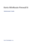
Connected to MX-ONE TSE
The figure below shows a typical setup for the MX-ONE Telephony
Server.
Figure 2: Typical MX-ONE Telephony Server setup
Connected to BusinessPhone
These IP phones can be used together with BusinessPhone version 7 or
later.
Connected to MD Evolution
These IP phones can be used together with MD Evolution version 8 or
later
1531-DBC 422 02 Uen B3 2013-12-02
4
DBC 422 AND DBC 425
1.2
Environmental requirements
The products covered in these installation instructions comply with the
prerequisites stipulated for placing appliances in office and exchange
room environments.
2
Aids
Wall mounting requires additional screws and spacers, 7.50 Wall
mounting of the IP phone on page 88
3
Preparations
Check that an Ethernet cable is available and verify that it is possible to
connect to the LAN.
4
Power equipment
The IP phone can either be powered from a 24 V AC/AC adapter or from
a power hub. If it is powered from an adapter the following alternatives
exist:
•
RES 141 312/1 for the EU market except for the UK (230 V)
•
RES 141 314/1 for the UK market (230 V)
•
RES 141 318/1 for the 110 V markets
For other markets the AC/AC adapter is locally sourced. The phone can
also be powered with 24-48 Volts DC.
Power consumption: 2.6 W (only the phone) and 4 W with the AC/AC
adapter included. An extra key panel requires 0.03 W.
As an alternative the IP phone can be powered via the LAN from a power
hub. The phone supports the standard IEEE 802.3AF for power over
LAN.
5
1531-DBC 422 02 Uen B3 2013-12-02
EARTHING/GROUNDING
These phones comply with the power class signature. The phone reports
power class 1 which means less than 4 W required.
5
Earthing/grounding
No special earthing or grounding is needed.
The IP phone needs a shielded Ethernet cable for the network connection.
1531-DBC 422 02 Uen B3 2013-12-02
6
DBC 422 AND DBC 425
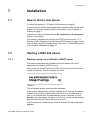
6
Cabling
The maximum line length between an IP phone and the LAN is 100
metres (328 feet) according to IEEE 802.3. Category 5 cables are
recommended.
The following Ethernet category 5 cable can be ordered from Aastra:
•
TSR 901 0452/3000
The figure shows where all the cables are to be connected in the bottom
of the phone.
Figure 3: Connection of the phone
7
1531-DBC 422 02 Uen B3 2013-12-02
INSTALLATION
7
Installation
7.1
How to start a new phone
To select the protocol, 7.6 Select H.323 protocol on page 21.
Connect one end of the network cable to the network outlet and the other
end to the connector marked LINE on the bottom of the IP phone. 6
Cabling on page 7.
If there is no LAN connection the text No connection to the network is
shown in the display.
This section is divided into one part if a DHCP server is used, 7.3.1
Starting a DBC 425 phone in a LAN with a DHCP server on page 14 and
into one part if fixed IP addresses are to be used 7.3.2 Manually setting
of the fixed IP addresses on page 18.
7.2
Starting a DBC 422 phone
7.2.1
Starting a phone in a LAN with a DHCP server
This section describes the procedure when the phone will use IP
addresses provided by a DHCP server.
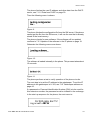
After power up of the IP phone the LED at the mute key will be lit for a
couple of seconds. Then the display will show:
Figure 4:
The x indicates a timer counting down seconds.
If the system administrator wants to change the IP settings, the administrator mode must be entered before the timer x is counted down to
zero. If no procedure for the administrator mode is entered, or if the
Speaker -key is pressed, the phone will use the current stored settings
and continue with the menu LAN access control.
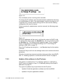
If the procedure for administrator mode is entered, the following menu
appears:
1531-DBC 422 02 Uen B3 2013-12-02
8
DBC 422 AND DBC 425
Figure 5:
Verify that the DHCP parameter is set to Yes, otherwise press the
Speaker key and change the value to Yes.
Normally the phone gets the IP address to the SW server automatically
from DHCP option 43 or from DNS SRV records. Step down in the
Network menu list and check that the parameter for Auto SW Server is
set to Yes.
A number of more IP settings can be done. For a complete survey of all
menus in the Network settings, see 7.34.4 Change IP settings in DBC
422 on page 70.
Use the C -key to leave the settings menu and continue the boot
sequence.
If LAN access control according to IEEE802.1x is enabled in the LAN,
the following menu appears:
Figure 6:
Enter the LAN access control user identity and press the Speaker key.
Figure 7:
Enter the LAN access control password and press the Speaker key.
If the authentication is successful the normal boot sequence continues:
Figure 8:
9
1531-DBC 422 02 Uen B3 2013-12-02
INSTALLATION
The phone fetches the own IP address and other data from the DHCP
server, see 7.11.2 Data from DHCP on page 30.
Then the following menu is shown:
Figure 9:
The phone fetches the configuration file from the SW server. If the phone
cannot get the file from the SW-server, it will use the one that is already
stored in the local memory.
The phone checks for new software. If the software will be updated
continue to 7.3.3 Update of the software in the IP phone on page 19.
Otherwise the following menus are shown:
Figure 10:
The software is loaded internally in the phone. This process takes about
15 seconds.
Figure 11:
The phone performs a test to verify operation of the phone circuits.
The next step is to set the IP address to the gatekeeper. To set the IP
address to the gatekeeper in H.323, see 7.14 Gatekeeper address on
page 46.
If a password or Personal Identification Number (PIN) is to be used for
this extension number, the password must be initiated in the exchange.
In the start up sequence for the phone, the next menu is:
1531-DBC 422 02 Uen B3 2013-12-02
10
DBC 422 AND DBC 425
Figure 12:
If the emergency call function is disabled the display shows:
Figure 13:
The next step is to register the phone towards the gatekeeper. The IP
extension must already be initiated in the system. The directory number
used at the previous log on is shown. If the number is to be changed,
enter the new extension number. Press the Speaker key to log on.
If the gatekeeper requires that a password or PIN must be used, the
following menu is displayed:
Figure 14:
Enter the password or PIN and press the Speaker key.
Figure 15:
Now the phone is ready for making and receiving calls.
The description of how to use the phone, see the directions for use for
each platform.
7.2.2
Manually setting of the fixed IP addresses
If a DHCP server is not used in the LAN, fixed IP addresses must be
used. The fixed IP addresses must be entered in the phone manually.
After power up of the IP phone, the display will show a special pattern
and the headset LED will be lit for a couple of seconds. Then the display
will show:
11
1531-DBC 422 02 Uen B3 2013-12-02
INSTALLATION
Figure 16:
The x indicates a timer counting down seconds.
To change the IP settings, enter the administrator mode before the timer
x is counted down to zero. If the administrator mode is not entered, or C
is pressed, the currently stored settings will be used and the Getting
configuration file menu is shown.
If the procedure for administrator mode is entered, the following menu
appears:
Figure 17:
If fixed IP addresses will be used, verify that the value for DHCP is No.
To change this value, press the Speaker key, the + key and then press
the Speaker key. The Network menu appears again. For a complete
survey of all menus in the Network settings, see 7.34.4 Change IP
settings in DBC 422 on page 70.
Enter the IP settings by using the +, - and Speaker keys for the entries
in the list.
Press the C key to exit from the settings menu and to continue the boot
procedure.
After this, the start up sequence is similar to the one when using DHCP,
see 7.2.1 Starting a phone in a LAN with a DHCP server on page 8.
7.2.3
Update of the software in the IP phone
This section is reached from 7.2.1 Starting a phone in a LAN with a
DHCP server on page 8 or from 7.2.2 Manually setting of the fixed IP
addresses on page 11.
Two types of updates may be performed on the IP phone:
•
Update of both the application software and the bootROM.
•
Update of only the application software.
1531-DBC 422 02 Uen B3 2013-12-02
12
DBC 422 AND DBC 425
Note: It is not possible to only update the boot software. If the boot software will be updated, the application has to be updated as well.
The following menu appears if a new bootrom shall be loaded:
Figure 18:
Press the Speaker key to update the software.
The x indicates a timer counting down seconds. If the C key is not
pressed during this time, the update is selected automatically.
If the C key is pressed, the phone will use the current version of the software.
When the Speaker key is pressed, the following menus are shown:
Figure 19:
When the bootrom firmware is loaded, the phone restarts and after a
while the following menu is shown:
Figure 20:
The application firmware is fetched from the SW server and loaded into
the IP phone and then the following menu is displayed:
Figure 21:
It is important that the power to the phone is not disconnected while this
text is shown in the display. This process takes a couple of minutes. If
13
1531-DBC 422 02 Uen B3 2013-12-02
INSTALLATION
there is a power failure during this phase, the phone has to load the software again.
The next menu shows Selftest OK.
The next step is to set the gatekeeper’s IP address and register the
extension towards the gatekeeper. This is described in 7.2.1 Starting a
phone in a LAN with a DHCP server on page 8.
7.3
Starting a DBC 425 phone
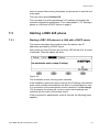
7.3.1
Starting a DBC 425 phone in a LAN with a DHCP server
This section describes the procedure when the phone uses IP
addresses provided by a DHCP server.
After power up of the IP phone the mute key LED will be lit for a couple
of seconds. Then the display will show:
Figure 22:
The x indicates a timer counting down seconds.
If the installation personnel want to change the IP settings, the administrator mode must be entered before the timer x is counted down to zero.
If no procedure for the administrator mode is entered, or if No change
(F4) is pressed, the phone will use the current stored settings and
continue with the menu LAN access control.
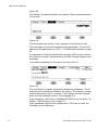
If the procedure for administrator mode is entered, the following menu
appears:
1531-DBC 422 02 Uen B3 2013-12-02
14
DBC 422 AND DBC 425
Figure 23:
Verify that the DHCP parameter is set to Yes, otherwise press the Select
(F4) key and change the value to Yes.
Normally the phone gets the IP address to the SW server automatically
from DHCP option 43 or from DNS SRV records. Step down in the
Network menu list and check that the parameter for Automatic SW
Server is set to Yes.
A number of more IP settings can be done. For a complete survey of all
menus in the Network settings, 7.34.5 Change IP settings in DBC 425
on page 73.
Use the home key to leave the settings menu and continue the boot
sequence.
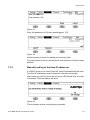
If LAN access control according to IEEE802.1x is enabled in the LAN,
the following menu appears
Figure 24:
Enter the LAN access control user identity and press the log on soft key.
15
1531-DBC 422 02 Uen B3 2013-12-02
INSTALLATION
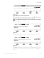
Figure 25:
Enter the LAN access password and press the Log on key.
If the authentication is successful the normal boot sequence continues.
The following menu appears:
Figure 26:
The phone fetches the own IP address and other data from the DHCP
server, 7.11.2 Data from DHCP on page 30.
Then the following menu is shown:
Figure 27:
The phone tries to fetch the configuration file from the SW server. If the
phone cannot get the file from the SW-server, it will use the one that is
already stored in the local memory.
The phone checks for new software. If the software will be updated
continue to section 7.3.3 Update of the software in the IP phone on page
19.
Otherwise the following menus are shown:
1531-DBC 422 02 Uen B3 2013-12-02
16
DBC 422 AND DBC 425
Figure 28:
The software is loaded internally in the phone. This process takes about
15 seconds.
Figure 29:
The phone performs a test to verify operation of the phone circuits.
The next step is to set the IP address to the gatekeeper. To set the IP
address to the gatekeeper in H.323, 7.14 Gatekeeper address on page
46.
If a password or Personal Identification Number (PIN) is to be used for
this extension number, the password or the PIN must be initiated in the
exchange.
In the startup sequence for the phone, the next menu is:
Figure 30:
The next step is to register the phone towards the gatekeeper. The IP
extension must already be initiated in the system. The directory number
used at the previous log on is shown. If the number must be changed,
enter the new extension number. Press Log on (F4).
If the emergency call function is disabled the SOS text is not shown. To
enable, 7.38 Emergency call on page 76.
If the gatekeeper requires that a password or PIN must be used, the
following menu is displayed:
17
1531-DBC 422 02 Uen B3 2013-12-02
INSTALLATION
Figure 31:
Enter the password or PIN and press Log on (F4).
Figure 32:
Now the phone is ready for making and receiving calls.
For a description of how to use the phone, see directions for use for each
platform.
7.3.2
Manually setting of the fixed IP addresses
If a DHCP server is not used in the LAN, fixed IP addresses will be used.
The fixed IP addresses must be entered in the phone manually.
After power up of the IP phone the mute key LED will be lit for a couple
of seconds. Then the display will show:
Figure 33:
The x indicates a timer counting down seconds.
1531-DBC 422 02 Uen B3 2013-12-02
18
DBC 422 AND DBC 425
To change the IP settings, enter the administrator mode before the timer
x is counted down to zero. If the administrator mode is not entered, or
No change (F4) is pressed, the currently stored settings will be used and
the Getting configuration file menu is shown.
If the procedure for administrator mode is entered, the following menu
appears:
Figure 34:
If fixed IP addresses will be used, verify that the value for DHCP is No.
For a complete survey of all menus in the Network settings, 7.34.5
Change IP settings in DBC 425 on page 73.
Enter the necessary IP settings.
Press Exit (F1) to continue the boot procedure.
After this, the start up sequence is similar to the one when using DHCP,
see 7.3.1 Starting a DBC 425 phone in a LAN with a DHCP server on
page 14.
7.3.3
Update of the software in the IP phone
This section is reached from the section, 7.3.1 Starting a DBC 425 phone
in a LAN with a DHCP server on page 14 or from the section 7.3.2 Manually setting of the fixed IP addresses on page 18.
Two types of updates may be performed on the IP phone:
•
Update of both the application software and the bootROM.
•
Update of only the application software.
Note: It is not possible to only update the boot software. If the boot software will be updated, the application has to be updated as well.
The following menu appears if a new bootrom shall be loaded:
19
1531-DBC 422 02 Uen B3 2013-12-02
INSTALLATION
Figure 35:
Press (Yes) (F3) to update the software.
The x indicates a timer counting down seconds. If the No (F4) key is not
pressed during this time, Yes is selected automatically.
If No (F4) is pressed, the phone will use the current version of the software.
When Yes (F3) is pressed, the following menus are shown:
Figure 36:
When the bootrom firmware is loaded, the phone restarts and after a
while the following menu is shown:
Figure 37:
The Application firmware is fetched from the SW server and loaded into
the IP phone. This may take about one minute and the following menu is
displayed:
1531-DBC 422 02 Uen B3 2013-12-02
20
DBC 422 AND DBC 425
Figure 38:
It is important that the power to the phone is not disconnected while this
text is shown in the display. This process takes a couple of minutes. If
there is a power failure during this phase, the phone has to load the software again.
The next menu shows Selftest OK.
The next step is to set the gatekeeper’s IP address and register the
extension towards the gatekeeper. This is described in section 7.3.1
Starting a DBC 425 phone in a LAN with a DHCP server on page 14.
7.4
Delivery method
The IP phone is delivered in a box together with two foot consoles, one
handset, one handset cord, designation labels, designation covers and
an assembly instruction.
Extra key panels are delivered separately.
The phone is delivered with the software version that was valid when the
phone was produced. The configuration file must be adapted for each
site and has to be loaded into the phone, 7.7 SW loading on page 22.
7.5
Connection of the handset
The handset cord is connected with one end (short uncoiled) to the
handset and the other end (long uncoiled) to the connector on the
bottom of the IP phone marked HANDSET.
7.6
Select H.323 protocol
The phone is delivered with the H.323 protocol enabled.
21
1531-DBC 422 02 Uen B3 2013-12-02
INSTALLATION
7.7
SW loading
The software to be loaded into the phone is to be stored on a web server
with HTTP protocol. This web server is called SW server in the menus
and in this document. The following files are stored on the SW server:
d42x02-applic_R1A.dat
(CAA 158 0043) The application firmware for the DBC 42x 02
phones. R1A in the file name is an example.
d42x02-boot_R1A.dat
(CAA 158 0044) The boot ROM firmware. This software is used to
be able to load the application into the IP phone. R1A in the file
name is an example.
d42x02-config.txt
(CAA 158 0042) The configuration file. This file contains information about the version of the software to be used and other configuration data. Normally the configuration file has to be adapted for
each installation, see the description for CONFIGURATION FILE
FOR DBC 42X.
d42x02-lang_R1A.txt
(CAA 158 0045) The language file containing all the languages that
are supported. R1A in the file name is an example. See the description for LANGUAGE FILE FOR DBC42X 02.
When the IP phone is powered up, the phone fetches the configuration
file from the SW- server. If the software version defined in the configuration file is different than the software version in the phone, the phone
fetches the application software file and/or the boot ROM software file
from the SW server. The new software is automatically stored into the
flash memory in the phone.
It is possible to load both newer and previous software versions with this
method.
To check the software version in the phone, see 7.25 Software version
on page 63
7.8
Several configuration files
A certain group of IP phones can often have different characteristics
compared to the other groups of extensions concerning which codec to
use, domain names, emergency number data etc. The following
methods exist to get different configuration files for the groups of
phones:
•
Use the DNS (Domain Name Service) domain name received from
DHCP, 7.11.2 Data from DHCP on page 30.
1531-DBC 422 02 Uen B3 2013-12-02
22
DBC 422 AND DBC 425
•
Use the telephony domain name received in the vendor specific
field in the DHCP messages, 7.11.2 Data from DHCP on page 30.
•
Subnet method, 7.8.3 Subnet method on page 23
•
Set the IP address of the SW server manually in the phone. In this
case there must be one SW server per configuration file.
For all the methods, the corresponding directory names have to be
created in the software server and the corresponding configuration files
have to be stored under these directories.
7.8.1
DNS domain name
The DNS domain name, provided in option 15 in DHCP, is used to create
the URI (universal resource identifier) to fetch the configuration file from
the software server.
Example: /dns_domain_name/dbc42x02/d42x02-config.txt, see 7.9.3
Directory structure on page 25.
7.8.2
Telephony domain name
If the DNS domain name cannot be used, it is possible to create telephony domain names and these are sent as a tag in option 43 in DHCP.
If the IP phone finds this tag, it will create the URI containing this domain
name and fetch the configuration file from the software server. Example:
/telephony_domain_name/dbc42x02/d42x02-config.txt, see 7.9.3 Directory structure on page 25.
7.8.3
Subnet method
The URI consists of the network address together with the subnet mask
length. The network address consists of the IP address of the phone with
a logical AND operation of the subnet mask.
Example: The phone has the IP address 130.100.26.144 and the subnet
mask is 255.255.255.192. The AND operation gives the URI
/130.100.26.128-26/dbc42x02/d42x02-config.txt. The component -26 is
the length of the subnet mask (number of ones in the binary value of the
subnet mask), see 7.9.3 Directory structure on page 25.
7.8.4
Priority between the different methods
The priority is:
23
•
The telephony domain tag in option 43
•
The DNS domain in option 15
1531-DBC 422 02 Uen B3 2013-12-02
INSTALLATION
7.9
•
Subnet method
•
The default configuration file is fetched. This file is stored under
/dbc42x02/dbc42x02-config.txt.
Software Server (SW server)
A software server with the HTTP protocol is used for storing the firmware
for the IP phone.
The IP address to the software server can be provided by one of the
following methods:
•
Manually in the Network menu or via the administrator web interface.
•
DHCP, 7.11.2 Data from DHCP on page 30. This method has
priority over the DNS SRV method.
•
DNS SRV resource records, 7.10 DNS SRV resource records on
page 27.
In a MX-ONE environment, the host for the Telephony Server and the IP
phone software server cannot be the same.
7.9.1
Installation
Installation of the HTTP server should be done according to the manufacturer’s documentation. Both PC and Unix versions are supported.
7.9.2
HTTP servers
As the SW server, the following http servers have been tested with the
IP phone:
•
Microsoft® NT4.
•
Microsoft® Windows® 2000 and 2003 server. When using
Windows® server the file type .dat must be enabled: In IIS
Manager , go to DefaultWEB Site , select Properties , edit HTTP
header , set Associated extension: .dat and set Content type
(MIME): application /octet-stream
•
Apache 1.3.3 on Microsoft® Windows® or on Redhat® Linux 5.2.
•
Apache Tomcat. When the IP Phone Configuration File task in
MX-ONE Manager TS shall be used the Tomcat server is mandatory. For more information, see the description for CONFIGURATION FILE FOR DBC 42X
1531-DBC 422 02 Uen B3 2013-12-02
24
DBC 422 AND DBC 425
The files according to section, see 7.7 SW loading on page 22, must be
stored on the server. The file names must be according to what is
described below, 7.9.3 Directory structure on page 25.
Note: When storing the files on the software server, make sure that the
files are transferred in binary mode, otherwise extra bytes can be
modified by the transfer tool and the size be changed. In this case
the telephone will not load the file.
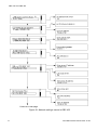
7.9.3
Directory structure
The directory structure under the http root directory must be created, see
figure 39 Directory structure using domain names on page 26. When
several different configuration files must be used for different groups of
phones where each group is a member of a specific domain, the structure with different domain names are used. In this case the configuration
files have the same name although they have different contents to define
characteristics for the different groups of phones.
The domain name is described above, see 7.8 Several configuration
files on page 22.
It is only the configuration file, and not the application and boot, that
needs to be stored under each domain directory name.
If the phones do not find any configuration file in a domain directory, the
file in the directory web-server root/dbc42x02 is used.
The application, boot and language files are stored in the dbc42x02
directory.
25
1531-DBC 422 02 Uen B3 2013-12-02
INSTALLATION
text in bold = directory name
plain text = file name
root
dbc44x01
dbc43x01
dbc42x02
d42x02-applic_r1a.dat
d42x02-config.txt
d42x02-lang_r1a.txt
d42x02-boot_r1a.dat
dby412
ringtones
certificates
8021X
H323
domain1
cacert.pem
dbc42x02
dbc43x01
d42x02-config.txt
d43x01-config.txt
dbc44x01
d44x01-config.txt
domain2
dbc42x02
dbc43x01
d42x02-config.txt
d43x01-config.txt
dbc44x01
d44x01-config.txt
Figure 39:Directory structure using domain names
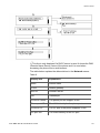
If the subnet method is used, 7.8.3 Subnet method on page 23, the directory structure will be as in the example below. In this example the phones
belonging to the first group have the network address 130.100.26.128
with the subnet mask 255.255.255.192. The second group has the
network address 130.100.27.0 with the subnet mask 255.255.255.0.
1531-DBC 422 02 Uen B3 2013-12-02
26
DBC 422 AND DBC 425
text in bold = directory name
plain text = file name
root
dbc44x01
dbc43x01
dbc42x02
d42x02-applic_r1a.dat
d42x02-config.txt
d42x02-lang_r1a.txt
d42x02-boot_r1a.dat
dby412
ringtones
certificates
130.100.26.128-26
dbc42x02
dbc43x01
8021X
H323
cacert.pem
d42x02-config.txt
d43x01-config.txt
dbc44x01
d44x01-config.txt
130.100.27.0-24
dbc42x02
dbc43x01
d42x02-config.txt
d43x01-config.txt
dbc44x01
d44x01-config.txt
Figure 40:Directory structure using the subnet method
7.10
DNS SRV resource records
To get necessary IP addresses into the phone, one option is to use the
DNS (Domain Name Server) SRV (service) resource records. The
following data can be retrieved in this way:
•
27
The IP address to the software server. To get this option, set the
data in following way: In Network settings, chose Automatic SW
server = YES but do not initiate this data in option 43 in DHCP. In
1531-DBC 422 02 Uen B3 2013-12-02
INSTALLATION
this case the phone will get the SW server IP address from DNS
SRV.
•
The IP address to the IP Phone Administrator server.
•
The IP address to the SIP proxy server
The DNS SRV handling does only work when DHCP is used and when
the DHCP server points out the DNS server and when a domain name
is received in DHCP option 15. This service is described in the RFC
2782.
With this method the phone sends a request to the DNS server to get a
particular service. This is an advantage compared to using option 43 in
the DHCP messages, which all the devices on the LAN receive. If a
device does not handle option 43 in a correct way, this can cause problems for this device.
In the answer from the DNS server the phone can get a list with hosts.
7.10.1
Enter data in DNS SRV resource records
The IP address to the software server
In the DNS SRV resource records, the following data has to be set to find
the IP address to the SW-server:
Service
_aas442x_cfg._tcp (applications up to and including R7K)
_aasdbc_cfg._tcp (applications from R7M and later)
Protocol
_tcp
Prio
The priority of the target host. The phone will try to contact the
target host with the lowest-numbered priority. Target hosts with the
same priority should be tried in pseudo random order. The range is
0-65535.
Weight
A load balancing mechanism. When selecting a target host among
those that have the same priority, the chance of trying this one first
is proportional to its weight. The range is 1-65535. Domain administrators shall use Weight = 0 when there is not any load balancing
to do.
Port
80 (fixed value)
Host
The DNS name of the Software server
1531-DBC 422 02 Uen B3 2013-12-02
28
DBC 422 AND DBC 425
The IP address to the IP Phone Administrator server
In the DNS SRV resource records, the following data has to be set to find
the IP address to the IP Phone Administrator server:
Service
_aas442x_smgt._tcp (applications up to and including R7K)
_aasdbc_sgmt._tcp (applications from R7M and later)
Protocol
_tcp
Prio
The priority of the target host. The phone will try to contact the
target host with the lowest-numbered priority. Target hosts with the
same priority should be tried in pseudo random order. The range is
0-65535.
Weight
A load balancing mechanism. When selecting a target host among
those that have the same priority, the chance of trying this one first
is proportional to its weight. The range is 1-65535. Domain administrators shall use Weight = 0 when there is not any load balancing
to do.
Port
8080
Host
The DNS name of the IP Phone Administrator server
7.10.2
Verification of entered data
The data entered into a DNS SRV resource record can be verified in a
PC by:
29
•
Open a DOS prompt window
•
Enter the command nslookup. The response will show the current
DNS server
•
Enter set type=srv
•
Enter the wanted service. Example: _aasdbc_cfg._tcp. domain
name where the domain name is the one the phone receives from
DHCP.
•
The response will contain the DNS SRV resource record data,
including the host name to the requested service
1531-DBC 422 02 Uen B3 2013-12-02
INSTALLATION
7.11
DHCP server
7.11.1
Installation
Installation of the DHCP (Dynamic Host Configuration Protocol) server
should be done according to the documentation of the manufacturer.
Both PC and Unix versions are supported.
The following DHCP servers have been tested with the IP telephone:
7.11.2
•
Microsoft® Windows® NT4.
•
Microsoft® Windows® 2000 and 2003 server.
•
Redhat® Linux.
Data from DHCP
The telephone has support for DHCP by which the following IP configuration data can be provided:
•
Own IP address, subnet mask and default gateway, received in the
DHCP standard fields (1 and 3).
•
The domain name for the LAN segment (DNS domain name) in
code 15. The domain name is used in the automatic gatekeeper
discovery routine, see section 7.15 Automatic Gatekeeper
Discovery on page 47. It can also be used when several configuration files are used, see section 7.8 Several configuration files on
page 22.
•
The vendor specific field 43 can be used to get the following data:
•
–
IP address of the software server, see section 7.9 Software
Server (SW server) on page 24.
–
IP address and port number of the http proxy server. If the
software is to be loaded from a SW server outside the firewall
the proxy settings are needed.
–
The telephony domain name. This can be used in the automatic gatekeeper discovery routine, see section 7.15 Automatic Gatekeeper Discovery on page 47. It can also be used
when several configuration files are used, see section 7.8
Several configuration files on page 22.
–
A list with VLAN identities. These are used when the telephone will automatically be assigned to a VLAN, see section
7.20 Virtual LAN (VLAN) on page 51.
DNS identity (web address) for the telephone.
1531-DBC 422 02 Uen B3 2013-12-02
30
DBC 422 AND DBC 425
For the complete usage of the domain name, see section 7.17 Domain
name on page 49.
7.11.3
DHCP Settings for Option 43 and 60
DHCP option 60 (vendor class identifier) and option 43 (vendor specific
information field) are used by the telephone to get the specific configuration data from the DHCP server. The flow is as follows:
Figure 41:
The procedure to initiate the data for option 43 and 60 in the DHCP
server is as follows:
7.11.3.1
1)
define vendor class (option 60)
2)
set predefines options (option 43)
3)
set scope options (option 43)
Vendor Class Identifier
Vendor class identifier (option 60) option is used to secure that option 43
data for the specific vendor is sent from the DHCP server to the client.
The telephone sends the vendor class identifier to the DHCP server,
which returns vendor specific information for the requested vendor class
in option 43 to the telephone.
When vendor class identifier shall be used to get the option 43 data for
the Aastra IP-Phone, it is necessary to initiate the vendor class Aastra
IP-Phone in the DHCP server and in some cases also the vendor class
31
1531-DBC 422 02 Uen B3 2013-12-02
INSTALLATION
Ericsson IP-Phone, see section 7.11.3.2 Vendor Specific Information
Field on page 32.
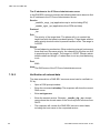
7.11.3.2
Vendor Specific Information Field
The vendor specific information field (option 43) is coded as shown in the
figure below.
Figure 42:Vendor Specific Information structure
Within this vendor field, a substructure is used with the different tags:
Tag 01 (T1 in the figure): SW server’s IP address in ASCII text format.
Tag 02 (T2 in the figure): Proxy server’s IP address also in ASCII text
format.
Tag 03 (T3 in the figure): Proxy port, also this in ASCII text format.
Tag 04 (T4 in the figure): Telephony domain name in ASCII text format.
Tag 05 (T5 in the figure): VLAN identity 1 for the telephone, in ASCII text
format.
Tag 06 (T6 in the figure): VLAN identity 2 for the telephone, in ASCII text
format.
1531-DBC 422 02 Uen B3 2013-12-02
32
DBC 422 AND DBC 425
Tag 07 (T7 in the figure): VLAN identity 3 for the telephone, in ASCII text
format.
Note: The VLAN identity for the telephone defined here in option 43
must not be equal to the VLAN identity for the PC defined in the
configuration file.
For more details about VLAN identity, see section 7.20 Virtual LAN
(VLAN) on page 51.
The different tags are optional, but if tag 02 is used tag 03 is mandatory.
The following applies for the ID string:
•
At new installation the string Aastra IP-Phone shall be entered in
DHCP option 43.
•
At upgrading (to application R7K or later and boot R3S or later) of
a site where the string Ericsson IP-Phone is used in DHCP option
43 and:
–
if vendor class (option 60) is used, it is mandatory to initiate
the new vendor class for Aastra IP-Phone.
–
if vendor class (option 60) is not used, the string Ericsson
IP-Phone can be kept in the DHCP server. The telephones
can handle both strings (but it is not allowed to have both
strings in the same option 43 structure).
The recommendation is to enter vendor classes in the DHCP server, one
vendor class for Aastra IP-Phone and another for Ericsson IP-Phone (in
case of new installation it is sufficient with only the first one). The vendor
specific information tags shall be equal within the two vendor classes.
See also section 7.11.3.1 Vendor Class Identifier on page 31.
7.11.4
Microsoft® Windows® 2003
Example of settings in Microsoft® Windows® 2003 server.
33
1531-DBC 422 02 Uen B3 2013-12-02
INSTALLATION
7.11.4.1
Define Vendor Class
Figure 43:Define Vendor Classes
Select Define Vendor Classes to get the menu where the vendor classes
are entered.
1531-DBC 422 02 Uen B3 2013-12-02
34
DBC 422 AND DBC 425
Figure 44: DHCP Vendor Classes
If the vendor class Aastra IP-Phone does not exist, press Add to create
the new vendor class. In the next menu the ID string Aastra IP-Phone
has to be entered:
35
1531-DBC 422 02 Uen B3 2013-12-02
INSTALLATION
Figure 45:Add Vendor Class
It is possible to move the cursor between the Binary and the ASCII area
to make it easier to enter the ID data.
When the data has been entered, press OK.
Close the window and proceed to set predefined options.
In some scenarios, the vendor class Ericsson IP-Phone has also to be
initiated, see section 7.11.3.2 Vendor Specific Information Field on page
32.
The Standard vendor class shall be avoided. It is sent out to all devices
that ask for option 43 data and if the device does not interpret the data
correct, it can cause problem.
7.11.4.2
Set Predefined Options
Figure 46:Set Predefined Options
Select Set Predefined Options to get the menu to enter option 43 data.
1531-DBC 422 02 Uen B3 2013-12-02
36
DBC 422 AND DBC 425
Figure 47: Predefined Options and Values
Select Aastra IP-Phone in the drop down list in the Option class field and
press the Add button.
The next menu is shown below:
Figure 48: Option Type
This is the default view and data has to be entered manually:
Name: Enter Vendor specific info
Data type: Select Binary in the drop down list
Code: Enter 43
Description: Can be left empty
37
1531-DBC 422 02 Uen B3 2013-12-02
INSTALLATION
The filled in dialog will look like:
Figure 49: Filled in Option Type Dialog
Press OK and the window with Predefined Options and values will occur
again. Press OK again and the menu will be closed.
7.11.4.3
Set Scope Options
Figure 50: Configure Options
1531-DBC 422 02 Uen B3 2013-12-02
38
DBC 422 AND DBC 425
Select Configure Options.
Figure 51:Scope Options
Select Advanced tab and scroll in the Vendor class field until Aastra
IP-Phone is selected. Press OK.
Next menu is where the ID strings and the tags are set, according to the
figure in section 7.11.3.2 Vendor Specific Information Field on page 32.
39
1531-DBC 422 02 Uen B3 2013-12-02
INSTALLATION
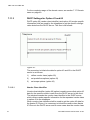
Figure 52:Windows® 2003 server DHCP settings
It is possible to move the cursor between the Binary and the ASCII area
to make it easier to enter the option 43 data.
This example shows that the total length of the vendor specific information is 0x1F, the length of the ID string is 0x0F and the string is Aastra
IP-Phone, The next byte 01 is the tag for the SW server's IP address,
0x0D is the length and then follows the IP address (10.105.88.100). If
more tags than tag 01 for the SW-server is needed, add the additional
tags according to the figure in section 7.11.3.2 Vendor Specific Information Field on page 32.
The picture below shows an example how option 43 can look like when
two vendor classes are initiated.
1531-DBC 422 02 Uen B3 2013-12-02
40
DBC 422 AND DBC 425
Figure 53:Two Initiated Vendor Classes
7.11.5
Linux DHCP settings
Example of settings in the Linux server:
subnet 192.168.6.192 netmask 255.255.255.192 {
option routers 192.168.6.254;
# class "Aastra IP-Phone" {
# match option vendor-class-identifier;
#}
# class "Ericsson IP-Phone" {
# match option vendor-class-identifier;
#}
if substring (option vendor-class-identifier, 0, 15)
= "Aastra IP-Phone"
{
option vendor-encapsulated-options "\x0fAastra
IP-Phone\x01\x0b192.168.0.1\x04\x16aastradomain.aast
ra.se\x05\x03452";
41
1531-DBC 422 02 Uen B3 2013-12-02
INSTALLATION
} else if substring (option vendor-class-identifier,
0, 17) = "Ericsson IP-Phone" {
option vendor-encapsulated-options
"\x11Ericsson IP-Phone
\x01\x0b192.168.0.1\x04\x16aastradomain.aastra.se\x0
5\x03452";
}
#
# DHCP settings continued
Example when using Vendor Class and the IP address for the sw-server
is 192.168.0.1, the telephony domain is aastradomain.aastra.se and the
VLAN identity is 452.
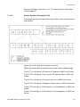
7.12
Diffserv
Diffserv is a model for handling of priority, based on the type of service
(TOS) field in the IP packet heading. For the definition of Diffserv 54 Diffserv octet on page 42
Figure 54:Diffserv octet
The default value for voice packets is Expedited Forwarding (EF) which
is 101110 (bit 0-5).
The default value for the signalling packets is for Traffic class = Class B
and Drop precedence = Medium drop precedence (010100 bit 0-5).
It is possible to change the values for Diffserv in the phone via the configuration file, see the description for CONFIGURATION FILE FOR DBC
42X.
1531-DBC 422 02 Uen B3 2013-12-02
42
DBC 422 AND DBC 425
7.13
IP Phone Administrator Tool
The tool IP Phone Administrator is used to monitor the DBC 42x 02 IP
phones in the network. This is useful in the following cases:
•
to find the IP address to the IP phones and especially to the phones
without a display.
•
to get an overview of all registered and not registered phones
•
to see the firmware version in both registered and not registered IP
phones
An alternative to IP Phone Administrator is to use the SNMP client in the
telephone, see section 7.13.2 SNMP agent on page 45.
The IP Phone Administrator is used in either of two ways depending on
the telephony system:
Table 1
MX-ONE TSE
Use the IP Phone Administrator
task, which is part of Manager
Telephony System. (No separate
installation is needed.)
MX-ONE TSW
and other platforms
Use the stand alone application
(product number CXC 109
0050), see section 7.13.1
Installation of the IP Phone
Administrator server on page 45.
Each phone is sending http messages to the IP Phone Administrator
server with data and events. The sent data are e.g. the MAC address,
the IP address, the hardware and firmware version and the extension
number. The events that can be sent are: the phone has started, the
phone is registered or not registered toward the PBX.
The IP Phone Administrator tool collects all the http messages from the
phones and has a Web GUI to present the data for the system administrator
It is possible to enable / disable the sending of these http messages from
the phone with a parameter in the configuration file, see the description
for CONFIGURATION FILE FOR DBC 42X.
The phones gets the IP address to the IP Phone Administrator server by
DNS SRV resource records or via the configuration file, see the description for CONFIGURATION FILE FOR DBC 42X.
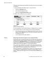
Below is an example of a printout from IP Phone Administrator:
43
1531-DBC 422 02 Uen B3 2013-12-02
INSTALLATION
Figure 55:IP Phone Administrator
A log in window will pop up when starting the tool. The user name and
the password is set by the system administrator at installation of IP
Phone Administrator.
The following columns exist in the GUI:
IP Address
Clicking on the IP address means that the web interface in the
phone is opened.
User
The name of the user that is registered or was registered before the
phone was logged off. This name is normally received in the phone
from the PBX, but can also be the name in the Contacts for the
actual extension number.
Extension
Extension number for the user that is registered towards the PBX,
or that was registered before the phone was logged off.
Status
An icon in different color is shown:
•
Red icon: the phone is not registered towards the PBX.
•
Green icon: the phone is registered.
1531-DBC 422 02 Uen B3 2013-12-02
44
DBC 422 AND DBC 425
•
Grey icon means: no log on attempt towards the PBX has
been done
•
Yellow icon with an exclamation mark: the phone has tried to
register but has got reject back from the gatekeeper.
•
Yellow icon: the phone has not reported anything to the IP
Phone Administrator since 48 hours.
MAC Address
The MAC address can also be found on the label under the phone.
Model
Type of phone.
HW rev
Hardware revision of the phone
Boot rev
Revision of the bootROM firmware in the phone.
Applic rev
Revision of the application firmware in the phone.
Last report
The time stamp when the phone sent a http message to the IP
Phone Administrator. Even if the status in the phone is not
changed, the phone sends an update once every 6:th hours.
Uptime
The time since last restart of the phone. The abbreviation d means
days.
Remove old entries
Removes entries for phones that has not sent any report during the
last 48 hours.
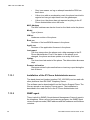
7.13.1
Installation of the IP Phone Administrator server
The stand alone tool (product number CXC 109 0050) can be used with
other platforms than MX-ONE Telephony Server.
The software can be downloaded from the Service Support Plaza. The
files are stored on an Apache Tomcat server. The installation is
described in the read me file for the IP Phone Administrator tool.
7.13.2
SNMP agent
There is a built in SNMP (Simple Network Management Protocol) agent in
the telephone. When using a port scanning program, the SNMP agent
returns the phone model, MAC-address and the hardware and firmware
revisions.
45
1531-DBC 422 02 Uen B3 2013-12-02
INSTALLATION
The SNMP agent is by default disabled, but can be enabled via the
configuration file. In this case it is mandatory to set the community string
in the configuration file, see description of configuration file for DBC42x.
The MIB (Management Information Base) OID (Object IDentifier) must
be 1.3.6.1.2.1.1.1.0.
For a more detailed description of the SNMP agent, see installation
instructions for DBC420.
7.14
Gatekeeper address
The IP address of the gatekeeper can be defined either in the configuration file or in the Settings - Network menu. To change these settings
from the menu, administrator mode must be used. The IP address of the
gatekeeper can be set by any of the following methods:
1
Automatic gatekeeper discovery. This is the method to get the IP
address automatically, 7.15 Automatic Gatekeeper Discovery on
page 47. The gatekeeper and the LAN (enabled for multicast) must
support this method. Verify that in the Network menu, Gatekeeper
Discovery is set to Yes or Default Yes.
2
In the configuration file. Primary gatekeeper can be defined, see
the description for CONFIGURATION FILE FOR DBC 42X. Verify
in the Network menu, that the parameter value is Gatekeeper
Discovery (Auto(No)).
3
In the configuration file. Secondary gatekeeper can be defined,
which will be used when the primary fails, see the description for
CONFIGURATION FILE FOR DBC 42X. Verify that in the Network
menu, that the parameter value is Gatekeeper Discovery
(Auto(No)).
4
Manually entered. Verify that in the Network menu, Gatekeeper
Discovery is set to No. Enter the administrator mode. Select the
Gatekeeper menu to enter the IP address.
5
Backup gatekeeper: the IP address of the backup gatekeeper is
defined in the configuration file, 7.37 Backup gatekeeper for branch
offices on page 75.
The table below shows which method that will be used depending on the
settings in the menus and in the configuration file. The digits refer to the
list above.
1531-DBC 422 02 Uen B3 2013-12-02
46
DBC 422 AND DBC 425
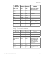
Table 2
Backup
GK Yes
Backup
GK No
Settings in the
configuration file
GateKeeper discovery
(Yes)
1,5
1
Any value
GateKeeper discovery
(No)
4,5
4
Any value
GateKeeper discovery
Auto (Yes)
1,5
1
GK discovery =
Yes
GateKeeper discovery
Auto (No)
2,3,5
2,3
GK discovery = No.
Primary and
secondary choice
available
GateKeeper discovery
Auto (No)
4,5
4
GK discovery = No.
Primary and
secondary choice
not available
Settings in menus
7.15
Automatic Gatekeeper Discovery
Only certain gatekeepers (PBXes) have support for Automatic gatekeeper discovery, for example MX-ONE TSW.
Automatic gatekeeper discovery is a method to find a gatekeeper (PBX)
to register to. When this method is used, the IP phone sends a multi-cast
message (Gatekeeper Discovery Request) and waits for a confirmation.
Several confirmation messages can be received.
The phone can send the domain name to inform the gatekeeper which
domain the phone belongs to. The domain name can be received from
DHCP 7.11.2 Data from DHCP on page 30 or from the configuration file.
The domain name provided by DHCP has priority over the domain name
defined in the configuration file.
The identity of the gatekeeper to which the phone is to be registered can
be defined in the configuration file. See data identifier GatekeeperID in
the description for CONFIGURATION FILE FOR DBC 42X.
The use, or not, of automatic gatekeeper discovery can be defined in the
configuration file and in the settings menu. By default the phone uses the
value defined in the configuration file.
47
1531-DBC 422 02 Uen B3 2013-12-02
INSTALLATION
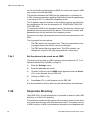
7.16
HLR Redundancy
HLR redundancy is a function in the MX-ONE TSE system. If the Line
Interface Module (LIM), where the data for the extension (Home Location Register) is stored, becomes unreachable, a temporary HLR will be
created in another LIM and the IP extension can register towards this
LIM.
The functionality of HLR Redundancy is different dependent on which
mode the phone is used in.
7.16.1
HLR Redundancy in H.323
The information in this part is valid for H.323.
7.16.1.1
Prerequisites
The HLR redundancy feature will only work when:
7.16.1.2
•
Automatic gatekeeper discovery (with multicast) is not used
•
The gatekeeper address is not set manually
•
Backup gatekeeper is not used (in branch office scenarios)
•
In the configuration file of the phone, both primary and secondary
gatekeeper (GK) address must be defined.
Change-over to Temporary HLR
The phone will use the primary GK address towards the entry GK in
MX-ONE, and receive a list of the GKs to be used. Alternatively the entry
GK could accept the registration directly. If a list is received, the phone
will try to register according to the list.
When the server (LIM) with the ordinary HLR becomes inaccessible,
there are two different cases:
•
The phone was registered in the LIM of the ordinary HLR. The
terminal will not receive any reply to the keep-alive check and will
then try re-registration to the secondary GK, according to the
configuration file. A temporary HLR will be created in the LIM where
the registration can be accepted.
•
The phone was registered in another LIM than in the ordinary HLR
LIM. This will happen if load distribution was used when trying to
register to the primary GK. A temporary HLR will be created in that
other LIM (where the phone was registered).
1531-DBC 422 02 Uen B3 2013-12-02
48
DBC 422 AND DBC 425
7.16.1.3
Change-back to Ordinary HLR
If the LIM of the ordinary HLR becomes available again, the periodic
keep-alive check request will be rejected by the GK (in the LIM of the
temporary HLR). The terminal will request a registration to the primary
GK, that is, in the LIM of the ordinary HLR.
The phone will then re-register according to the configuration file, that is,
to primary and secondary GK, in that order.
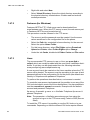
7.17
Domain name
The domain name is used:
7.18
•
In the function Automatic gatekeeper discovery to find a PBX to
register to, 7.15 Automatic Gatekeeper Discovery on page 47.
•
When several configuration files will be used, 7.8 Several configuration files on page 22. This domain name cannot be defined as a
parameter value in the configuration file.
•
In the registration request message when the gatekeeper is
MX-ONE TSW or MX-ONE TSE.
Selection of transport address (port
numbers)
The tables below show the port numbers used for signalling and media
in the phone. It is the receiving port numbers in the phone that are
shown.
Table 3 UDP ports used by the phone
Type of
signalling
49
Minimum
Maximum
DHCP client
68
68
SNMP
161
161
RAS/GRQ
1718
1718
RAS
1719
1719
Comment
Multicast
1531-DBC 422 02 Uen B3 2013-12-02
INSTALLATION
Type of
signalling
Minimum
Maximum
Comment
WAP (Push)
2948
2948
URQ in secure
mode
3727
3727
OMD
5000
5001
VoIP Recording
7300
7300
RTP
16986
17012
RTCP
16987
17013
RTP port + 1
WAP (Reply)
49152
49152
Receive from internal
WAP server (PBX)
WAP (Reply)
49153
49153
Receive from external
WAP server
Receive from internal
WAP server (PBX)
For speech
Table 4 TCP ports used by the phone
Type of
signalling
Minimum
Maximum
SSH
22
23
Secure Shell
Web Server Port
80
80
Web server in the phone
H.225 secure
port
1300
1300
Incoming call to the
phone, default value.
Can be 1722 if the
phone receives this
value in RCF.
H.245
1390
1396
H.225
1720
1720
1531-DBC 422 02 Uen B3 2013-12-02
Comment
Incoming call to the
phone
50
DBC 422 AND DBC 425
Type of
signalling
Minimum
Maximum
Comment
H.225 unsecure
port
1722
1722
Incoming call to the
phone: is 1722 if the
phone receives this
value in RCF.
The default number is
1300.
RAS over TCP
3727
3727
TLS signaling.
Web Browser
Port
8080
8080
When using the WAP
browser in the phone to
access external web
pages
Port number for Operator Media Device (OMD): the port number is set
in MX-ONE (OPSAI command). The same port number shall be set in
the configuration file for the telephone and in the configuration of the
Integrated Attendant Workstation, NOW (if applicable).
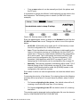
7.19
Built-in Ethernet switch
These phones have a built-in Ethernet switch with two available ports.
One port is used to connect the LAN and the other can be used by a PC.
The phone has support for the IEEE standards 802.1D (except spanning
tree) and for 802.1p&Q.
The frames sent from and to the phone (voice and signalling) are
handled with higher priority within the switch compared to the frames
sent from and to the PC.
7.20
Virtual LAN (VLAN)
The built in Ethernet switch can handle virtual LAN identities and priorities for the LAN port, for the phone port and for the PC port.
The following possibilities to assign VLAN identities exist:
51
•
From DHCP in option 43 (only the phone port, but not the PC port).
A list of maximum three VLAN identities can be handled, see figure
41.
•
From the configuration file (both the phone- and the PC port).
1531-DBC 422 02 Uen B3 2013-12-02
INSTALLATION
•
From a menu where it can be manually set (both the phone- and
the PC port).
It is possible to change the different VLAN options from the menu in the
boot sequence. The following menu is shown (for DBC 425 as an
example):
Figure 56: Start up menu in DBC 425
Enter the administrator mode, go down in the Network list until the line
VLAN for Phone Port occurs. Change the value to one of the options
below:
•
No VLAN. VLAN shall not be used, but if a VLAN identity is read
from the configuration file, VLAN will be used.
•
Auto. This is the default value when the phone is delivered from the
factory. If the phone receives a VLAN identity list from DHCP (in
option 43) or if there is a VLAN identity defined in the configuration
file it will be used. The VLAN identity received from DHCP has
priority over the configuration file. For more information, 7.20.1
Automatic VLAN detection with DHCP on page 53 and 7.20.2
Assigning the VLAN identity via the configuration file on page 53.
•
Manually. The manually entered VLAN identity will be used, 7.20.3
Manual setting of the VLAN identity on page 54. If the manually
entered VLAN identity shall be used, the [L2QOS] header in the
configuration file has to be omitted.
Even when VLAN is not used this parameter can have the default value
Auto.
Concerning the priority of the frames: For outgoing frames the following
priorities will be set at level 2 for each frame by default, when VLAN is
used:
•
For frames originating in the phone the default value will be 6,
meaning voice traffic with less than 10 ms latency.
•
For frames originating in the PC the default value is 0, meaning
best effort.
The priorities can be changed via the configuration file, see the description for CONFIGURATION FILE FOR DBC 42X.
1531-DBC 422 02 Uen B3 2013-12-02
52
DBC 422 AND DBC 425
7.20.1
Automatic VLAN detection with DHCP
Prerequisites on the LAN
When the phone is connected to a layer 2 switch, the switch will add the
IEEEE 802.1Q header, to untagged frames with the default VLAN identity and forward the frames. The first layer 3 switch must be initiated for
DHCP relay and having an ingress port with an IP address on each of
the offered VLANs. The address to the DHCP server must be set in the
layer 3 switch.
When the layer 3 switch has received a DHCP discover message, it will
forward this packet to the DHCP server adding the IP address of its
ingress port corresponding to the VLAN. It is this address information
that informs the DHCP server to which IP subnet that this phone is to be
assigned to.
Description of when a VLAN identity list is received from the native
LAN
At installation (and hardware reboot) the phone asks for a temporary IP
address from DHCP by initiating the DHCP negotiation with untagged
messages (native LAN). The relay agent adds the address of its ingress
port corresponding to the native LAN. DHCP provides the temporary IP
address together with the VLAN identity list. The phone releases the
temporary IP address.
Then the phone uses the first VLAN identity in the list and sends a new
tagged request to the DHCP server. The relay agent adds the address
of the ingress port corresponding to the selected VLAN. If there is any
available IP address, the DHCP server provides this address to the
phone. If there is no available IP address for this VLAN, the phone takes
the next VLAN id in the list and asks for an IP address.
If there is no IP address available in any VLAN in the list, the phone will
ask for an IP address in the native LAN.
Reboot
It is possible to specify in the configuration file whether the telephone
should retain the previously used VLAN identity after reboot, or whether
it should start a new automatic VLAN detection procedure. See description for Configuration file for DBC42x.
To change the VLAN identity:
See description for Configuration file for DBC42x.
7.20.2
Assigning the VLAN identity via the configuration file
The description of the parameters, see the description for CONFIGURATION FILE FOR DBC 42X.
The configuration file is read from the native LAN
53
1531-DBC 422 02 Uen B3 2013-12-02
INSTALLATION
At installation (and hardware reboot) the phone asks for an IP address
from DHCP by initiating the DHCP negotiation with untagged messages
(native LAN). DHCP provides the IP address but no VLAN identity list.
The phone reads the configuration file, but in this case when no VLAN
identity list is received from DHCP, a software reboot is done automatically in the phone to get the IP address valid for the tagged VLAN
defined in the configuration file.
The configuration file is read from the VLAN
At installation (and hardware reboot) and the configuration file is available in the VLAN but not in the native LAN, the VLAN identity must be
set manually in the boot menu.
7.20.3
Manual setting of the VLAN identity
Set the VLAN identity from the menu in the boot sequence. To use the
manual entered VLAN identity all the time, disable the VLAN settings in
the configuration file.
7.21
Security
There are two security features:
•
LAN access control, see 7.22 LAN access control (according to
IEEE802.1x) on page 58.
•
VoIP signalling with TLS and media encryption with SRTP. This is
described in this section.
The TLS and SRTP support can be enabled/disabled from the configuration file, see the description for CONFIGURATION FILE FOR DBC
42X section SECURITY.
In addition there is a security policy in the telephony system which also
affects the behavior of the IP phones. For MX-ONE Telephony Server,
see the description for SECURITY.
The security policy is checked at the registration time. Once the phone
is registered, all kinds of calls can be established from a security
perspective.
When a secure IP to IP call is established, with TLS and SRTP, a secure
icon (a padlock) is shown in the display. For all gateway calls the secure
icon is not shown because the other party can have an un-secure
connection. When there is a secure IP to IP call and IP voice recording
is active the secure icon is not shown.
1531-DBC 422 02 Uen B3 2013-12-02
54
DBC 422 AND DBC 425
7.21.1
Protection of VoIP signalling
The signalling between the DBC 42x 02 IP phones and the gatekeeper
is protected by means of TLS (Transport Layer Security) according to
RFC 2246.
The TLS protection affects the registration and the call handling. Multicast traffic (automatic gatekeeper discovery) is not protected.
The TLS server (gatekeeper) makes use of a digital certificate to authenticate itself towards the terminal. The terminal authenticate themselves
by means of the password (ordinary password to register towards the
gatekeeper) sent in the RAS/RRQ message.
TCP port 3727 is used for RAS over TCP.
TCP port 1300 is used for Secure Call Setup. For more information 7.18
Selection of transport address (port numbers) on page 49.
The cipher suite TLS_RSA_WITH_AES_128_CBC_SHA defined in
RFC 3268 is used.
TLS is not supported on top of UDP. In order to support TLS protection
of the RAS messages these are sent over a TCP connection, opened by
the IP phone, after a TLS connection has been set up.
The TLS support can be enabled/disabled from the configuration file,
see the description for CONFIGURATION FILE FOR DBC 42X.
7.21.1.1
Certificates
The digital certificates are in X.509 version 3 format with the file extension .pem. For more detailed information about creating the certificate,
see operational directions for Certificate Management in the CPI library.
In order for the phone to be able to authenticate the server, the phone
has a certificate repository with a number of root certificates or trusted
certificates (see the table below). These are included in the IP phone
firmware in the factory.
It is also possible to add another root certificates beside these by reading
in the file with the certificate from the software server. The file must be
stored under the folder /certificates/H323, see section 7.9.3 Directory
structure on page 25. The path to the certificate file is specified in the
configuration file.
Table 5 X.509 root certificates to support TLS server authentication
Certificate Authority
Comment
Baltimore
Entrust
55
md5WithRSAEncryption
1531-DBC 422 02 Uen B3 2013-12-02
INSTALLATION
Certificate Authority
Comment
Entrust
sha1WithRSAEncryption
Equifax CA-1
md5WithRSAEncryption
Equifax CA-2
sha1WithRSAEncryption
Equifax
sha1WithRSAEncryption
Equifax Secure Global
eBusiness CA-1
GTE Cyber Trust
QuoVadis Root CA2
SecureSign Root CA1
SecureSign Root CA2
SecureSign Root CA3
Tawnte Premium Server
CA
Tawnte Server CA
ValiCert Class 1
ValiCert Class 2
ValiCert Class 3
VeriSign Class 3
VeriSign Class 3 - G2
VeriSign Class 4 - G2
VeriSign Class 3 - G3
VeriSign Class 4 - G3
VeriSign Test Root CA
md2WithRSAEncryption
VeriSign Test Root CA
sha1WithRSAEncryption
1531-DBC 422 02 Uen B3 2013-12-02
56
DBC 422 AND DBC 425
7.21.1.2
Registration towards the gatekeeper
At log on the phone promts the user to enter the extension number and
the password or PIN. If the user do not have a password or PIN, the
phone tries to log on to the insecure UDP port1719.
In case the IP phone tries to log on securely but the establishment of the
TCP connection fails, this is interpreted as the gatekeeper does not
support secure mode. The phone shall back off to RAS over UDP. The
possibility to back off to UDP is managed via a parameter in the configuration file, see the description for CONFIGURATION FILE FOR DBC
42X.
During the TLS negotiation, the server will authenticate itself by using a
digital certificate, see 7.21.1.1 Certificates on page 55.
In the configuration file there is an option whether the client shall validate
the server certificate or not. If the option is enabled but the server does
not have a certificate that is signed by one of the Certificate Authorities
supported in the phone or if the certificate has expired, it will result in a
failed authentication.
There are two options in the configuration file for the password:
7.21.1.3
•
Do not store the password in the phone: The user needs to re-enter
the password each time the phone registers towards the gatekeeper, that is, after power failure, network failure, update of firmware. This option is not available for the DBC 420 phone, which do
not have the log on option from the key pad.
•
Store the password in the phone in the same way as when not
using TLS, that is the user only needs to re-enter the password
after the phone is manually logged off or when the phone has been
logged off after the extension number is used by another IP
terminal.
Call Setup and Call Control
When the IP phone that is registered securely, sets up a call using H.225
Q.931 messages, it sends the requests to TCP port 1300 instead of TCP
1722.
In order to negotiate the capability of the call, an H.245 negotiation takes
place on a new TCP connection between the terminal and the gatekeeper. The TCP port to be used is negotiated during the H.225
signaling. The TCP connection can be initiated by either part. This TCP
connection is protected by means of TLS as well.
This implies that during a call there can be three TCP connections
existing between the terminal and the gatekeeper.
57
1531-DBC 422 02 Uen B3 2013-12-02
INSTALLATION
7.21.2
UDP Filtering
All the UDP ports that are not used, can be blocked for security reasons.
For a description of all UDP and TCP ports, see 7.18 Selection of transport address (port numbers) on page 49.
The default value is that the UDP filtering is enabled, but can be disabled
with a parameter in the configuration file, see description of Configuration File for DBC 42x.
7.21.3
TCP filtering
All the TCP ports that are not used, can be blocked for security reasons.
For a description of all UDP and TCP ports, see 7.18 Selection of transport address (port numbers) on page 49.
The default value is that the TCP filtering is enabled, but can be disabled
with a parameter in the configuration file, see description of Configuration File for DBC 42x.
7.21.4
SRTP
Secure RTP, SRTP (RFC 3711), is supported by DBC 42x 02 phones.
The supported encryption algorithm is AES 128 (Advanced Encryption
Standard) in counter mode for SRTP and SRTCP. HMAC_SHA1_80 is
supported for SRTCP.
Media encryption is negotiated using H.245 i. e. both the capability as
well as the keys. (The key negotiation phase is based on H.235.8).
The following codecs have SRTP support: G.711 Α-law, G.711 µ-law,
G.723.1, G.729a and G.729ab.
Beside the possibility to enable/disable TLS and SRTP via the phone
configuration file, SRTP can be temporary disabled for a certain phone
via a SSH command.
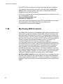
7.22
LAN access control (according to
IEEE802.1x)
The IEEE802.1x standard is used for port access control authentication.
The LAN must support IEEE802.1x signalling and there must be a
RADIUS server handling the authentication, according to EAP-MD5. The
system administrator, or the end-user, enters the user identity and the
password into the phone and if the authentication is successful, the
phone gets access to the LAN and continues with the ordinary boot
sequence.
1531-DBC 422 02 Uen B3 2013-12-02
58
DBC 422 AND DBC 425
Figure 57:Components in LAN access control
Before the authentication the phone cannot get access to the LAN or
even get the IP address from the DHCP server. The authentication has
to be performed periodically within 5 minutes (maximum).
If the LAN does not support IEEE802.1x, the phone will start in the ordinary way.
If a PC shall be connected to the PC port in the phone, the phone
supports that the PC and the phone are authenticated independent of
each other.
Note: The LAN switch must support that two devices are authenticated
independent of each other on the same LAN port.
7.22.1
Configuration of LAN access control
The default value is that the phone shall automatically detect if
IEEE802.1x is enabled in the LAN. In the boot menu, it is possible to
change the following values:
•
Auto. The phone will initiate IEEE802.1x signalling in the boot
sequence and if IEEE802.1x is enabled in the LAN, the phone
enables this function.
•
No. The phone disables the IEEE802.1x function. If IEEE802.1x is
enabled in the LAN and the parameter value is set to No, the phone
cannot access DHCP and the configuration file cannot be read.
The parameter values set in the boot menu is valid until the configuration
file is read by the phone. If the values in the boot menu shall be valid
even after the configuration file is read, the corresponding parameters in
the configuration file shall be disabled.
In the configuration file the following parameters exist:
59
1531-DBC 422 02 Uen B3 2013-12-02
INSTALLATION
•
LAN access control (Auto / No)
•
LAN access control user identity and password shall be stored in
the phone or not.
•
LAN access control user identity and password shall be valid for the
phone or for the end user. In the first case the phone shall not log
off from the LAN when register with a different extension number
towards the PBX. In the second case, the phone shall log off from
the LAN when entering a different extension number.
•
LAN access control user identity and password, which can be used
when all the phones shall have the same user identity and password.
For more details, see the description for CONFIGURATION FILE FOR
DBC 42X section 802.1X.
7.22.2
Examples of configuration
One typical case with basic level of security can be that all phones have
the same user identity and password. The configuration of all the phones
must be done via a switch where IEEE802.1x is disabled. Using the
default values the following configuration will be needed:
•
Automatic IEEE802.1x detection (default).
•
Define the user identity and the password in the configuration file.
•
The user identity and password are stored in the phone (default).
•
The user identity is valid for the phone, which means that the
end-user can change extension number towards the PBX, without
having to enter a new LAN access user identity and password
(default value).
•
Start the phone via the IEEE802.1x disabled switch. The phone will
read and store the user identity and password from the configuration file.
•
Set out the phone to the end-user and start it via the IEEE802.1x
enabled switch.
Another typical case with a higher level of security is that each phone
has individual user identity and password:
•
Automatic IEEE802.1 detection (default).
•
The user identity and password are stored in the phone (default).
•
The system administrator or end-user have to enter the LAN
access control user identity and password when starting the phone
only the first time.
1531-DBC 422 02 Uen B3 2013-12-02
60
DBC 422 AND DBC 425
•
7.22.3
The user identity is valid for the phone, which means that the
end-user can change extension number towards the PBX, without
having to enter a new LAN access user identity and password
(default value).
Authentication to the LAN
The authentication process starts in the boot sequence with that the
phone prompts the user to enter the user identity and password, 7.1 How
to start a new phone on page 8.
At restart of the phone, and when the user identity and password are
stored in the phone, the ordinary restart procedure is done which means
that the user does not have to do anything.
7.23
Access the phone from a PC
For maintenance of the terminal, the system administrator can from a PC
access the phone in one of the following ways:
•
Web interface. This interface is recommended.
•
SSH (Secure Shell). This interface is similar to a Telnet interface,
but the connection is secure.
In the maintenance PC, a SSH client must be used. There are a
number of free-ware clients, the must popular is PuTTY for PCs
with Windows®.
The default encryption keys are used and not possible to change.
For a description of these interfaces, see maintenance instructions for IP
TELEPHONE DBC 42X. See also 7.24.1 Password for maintenance on
page 62.
The end-user can also access the phone via the web interface. This
interface is described in the directions for use for each platform. See also
7.24.2 Web interface password for the end user on page 62.
7.24
Passwords
There are different passwords used in the phone:
•
61
to register the phone to the gatekeeper, see 7.2.1 Starting a phone
in a LAN with a DHCP server on page 8 and 7.3.1 Starting a DBC
425 phone in a LAN with a DHCP server on page 14. The recom-
1531-DBC 422 02 Uen B3 2013-12-02
INSTALLATION
mendation is to use such a password or PIN to avoid that one
end-user can log in with another end-user’s directory number.
7.24.1
•
for maintenance via SSH or the web interface, to be used by the
network administrator or other maintenance personnel, 7.24.1
Password for maintenance on page 62
•
for the end user when handling of data in the phone, via the web
interface, see 7.24.2 Web interface password for the end user on
page 62.
•
LAN access control authentication, see 7.22 LAN access control
(according to IEEE802.1x) on page 58.
Password for maintenance
A network administrator can log on from a PC to an IP phone via SSH.
It is also possible to access the phone from a web browser via the web
interface. It is the same password for both SSH and web browser
access. The default password is Telephone. This password can be
changed by using the following procedure:
•
Log in to one IP phone via SSH.
VxWorks login: admin
Password: Telephone
For more information about the functions when using Telnet, see
the maintenance instructions for IP TELEPHONE DBC 42X.
7.24.2
•
Enter the command encryptPasswd "new wanted password"
(quotation mark must be used). The password must be at least
eight (and maximum 40) characters. Letters A - Z, a - z and digits
can be used.
•
Write the generated encrypted password with the data identifier
AdminPassword in the configuration file, see the description for
CONFIGURATION FILE FOR DBC 42X. Store the updated configuration file on the SW server
•
Next time the IP phones read the updated configuration file the new
password is valid.
Web interface password for the end user
The end user can use the web-browser in a PC to access the web interface in the IP phone. The purpose is to set data in the phone like entries
in the Phone Contacts, the call list etc.
This password is the same as the password or PIN to register the phone
to the PBX. If there is no password or PIN initiated in the PBX, it is
1531-DBC 422 02 Uen B3 2013-12-02
62
DBC 422 AND DBC 425
possible to use the default password is Welcome to log in to the web
interface. But in this case a parameter must be changed in the configuration file to enable the default password option.
7.25
Software version
It is possible to check the software versions in the phone by pressing the
keys C (clear key), * and 4 simultaneously for at least one second.
The program revisions are shown in the display. To check that all pixels
are working, press the C-key. To get to the original mode again press the
# key.
Figure 58: Display of software versions in DBC 425
In the example above the version of the boot is R3A, the application R1A
and the language file R3A.
If there is a fault in the configuration file an error message is shown in
the display, see maintenance instructions for IP TELEPHONE DBC 42X.
7.26
Keys for DBC 422
7.26.1
Function-keys
In the Settings menus, the function-keys have the following functions:
Clear key
Cancel. Leave the current menu without changing anything.
Exit. Leave the current menu and go up one level in the menu hierarchy.
Speaker key
63
1531-DBC 422 02 Uen B3 2013-12-02
INSTALLATION
Select the current menu.
Save the entered data.
Volume keys
+ key is used to go down one row in a listancel.
- key is used to go up one row in a list and also to erase the latest
entered character.
The figure below shows an overview of what the keys are used to.
Figure 59:Hidden Key Functions
The functions assigned to the programmable function keys are possible
to move and remove, see 7.34.3 Allocation of function keys on page 70.
7.27
Keys for DBC 425
The functions assigned to the programmable function keys are possible
to move and remove, 7.34.3 Allocation of function keys on page 70.
7.27.1
Soft-keys
In the Settings menus, the soft-keys have the following functions:
Cancel (F1)
Leave the current menu without changing anything. Cancel is used
in menus where it is possible to change data.
1531-DBC 422 02 Uen B3 2013-12-02
64
DBC 422 AND DBC 425
Exit (F1)
Leave the current menu and go up one level in the menu hierarchy.
Exit is used in menus where it is not possible to change data.
Erase (F3)
Erase the latest entered character.
Select (F4)
Select the current menu.
Save (F4)
Save the entered data.
Down (F3)
Scroll down or to the right in the menu.
Up (F2)
Scroll up or to the left in the menu.
7.27.2
Navigation keys
The navigation keys are used to navigate in the menu bar on the top
display row:
<
one position to the left.
>
one position to the right.
Home
the home key to get to the idle menu from all other menus.
7.28
Restart and reboot of the phone
If it is necessary to restart or reboot the phone manually, press the keys
C (clear key), mute and # simultaneously for one or two seconds.
It is also possible to restart the phone and to reset all network settings
from the administrator web interface, see maintenance instructions for IP
TELEPHONE DBC 42X.
After a power failure or a reboot, the phone will log on automatically with
the stored directory number.
65
1531-DBC 422 02 Uen B3 2013-12-02
INSTALLATION
7.29
Factory default
To set the phone to factory default, the following procedure must be
used:
•
Enter administrator mode, 7.30 Administrator mode on page 66.
•
Press the keys C,*,9 for a second.
The following data will be set:
7.30
•
Use DHCP
•
Auto detection of protocol, which means that the telephone will use
the protocol H.323 that is defined in the configuration file
•
The phone shall retrieve the IP address to the software server automatically (from DHCP or DNS SRV resource records)
•
Automatic VLAN detection
•
Automatic detection of LAN access control according to
IEEE802.1x
•
User identity and password for LAN access control according to
IEEE802.1x
•
The password is erased
•
The contact list is erased
•
All the numbers associated to function keys are erased
•
All the function keys are placed on the default positions
•
Tone ringer character is set to the default value
•
Increased hearing level is set to standard
Administrator mode
The administrator mode is used when IP settings is to be changed.
Normally it is the maintenance personnel that handles the IP settings
and not the end user.
To enter the administrator mode, use the navigation key to get the
settings menu and then press the keys C (clear key), * and 5 simultaneously for one or two seconds. One ringing signal is heard to indicate that
this mode is entered. The administrator mode is valid until exiting from
the Settings menu.
1531-DBC 422 02 Uen B3 2013-12-02
66
DBC 422 AND DBC 425
7.31
Quality of Service (QoS)
It is possible to view the quality of service statistics of the connection for
the last 10 calls via the web interface. The statistics shows for example
the delay, jitter and number of lost packets. See maintenance instructions for IP TELEPHONE DBC 42X.
7.32
Language handling
The language file will be stored on the SW server and is fetched from the
server to the phone at start up of the phone. The end user may choose
a language other than English using the language menu in Settings
mode.
It is possible for the system administrator to change text strings e.g. for
Absence reasons. See the description for LANGUAGE FILE FOR DBC
42X 02.
7.33
Setting Time and Date
Time and date can be set using the following alternatives:
•
WAP messages. For PBX's supporting WAP, the time in the IP
phone is updated automatically as soon as the phone is registered
towards the PBX.
•
SNTP (Simple Network Time Protocol). The time in the phone can
be set via SNTP, as described below. This method must also be
used if security is enabled (with validation of the server certificate)
in the phones and in the system.
If the SNTP server is enabled and defined in the configuration file, the
phone will take the time from the SNTP server.
7.33.1
Simple Network Time Protocol
When SNTP is available in the LAN, the time and date in the phone are
updated automatically when the phone is started and is verified periodically. If SNTP is used, the IP address and the Time zone will be set in
the configuration file, see Configuration File for DBC 44X and DBC 43X.
If the LAN does not have SNTP or NTP available, a server with SNTP
software has to be initiated.
67
1531-DBC 422 02 Uen B3 2013-12-02
INSTALLATION
7.34
To change the configuration of the phone
7.34.1
Methods to change the configuration
It is possible to change the configuration in the phone by:
7.34.2
•
The menus, see directions for use for each platform.
•
The web interface, see directions for use for each platform.
•
The configuration file. The configuration file is read by the phone
when it is rebooted, either by an order from the PBX or manually or
via the web interface, see 7.28 Restart and reboot of the phone on
page 65.
The phones can fetch the configuration file from the SW-server
every 24:the hour and this option is enabled via a parameter in the
configuration file.
Log on / Log off options
The following options exist:
•
Log off allowed. The end-user is allowed to log on and log off the
phone. This is the default and most common option. It is possible
to force all the telephones to log off at a certain time each 24 hour
period, but only when the log off option is defined via the configuration file, see 7.34.2.1 Set the log off restriction option in the configuration file on page 69.
•
Default number used. The phone is always logged on with a
default number. The log off soft-key is not shown and the end-user
cannot log on or off. This option can be used for phones in conference rooms, receptions etc. The default number must have an
associated password to avoid logging off by mistake from an other
terminal. If the terminal is logged on when option 2 is set, the
current number will be the default number. If the phone is logged
off, after exiting the Settings menu, the system administrator will
be prompted to enter the number to be used as the default number.
•
Permit individual log on. The phone is always logged on, with a
default number, as in option above but the end-user can log on with
his/her individual number and get the personal categories. This
option can be used in a free seating environment. When the
end-user logs off the individual number, the phone registers automatically with the default number. The same if the end-user logs on
with the individual number from an other terminal. If the end-user
forgets to log off, the phone will log off the individual number and
will log on with the default number during the night.
1531-DBC 422 02 Uen B3 2013-12-02
68
DBC 422 AND DBC 425
The log on procedures are described in the directions for use for respective system.
To change between the different log on / log off options:
•
Select the Settings menu.
•
Enter the administrator mode.
•
Select the Log Off Restrictions menu.
For DBC 425, the following menu is shown:
Figure 60:
Select the wanted option.
It is also possible to use the web interface to change the log on options.
If the default number is to be changed, there are two possibilities:
7.34.2.1
•
Enter the administrator mode in idle mode and the log off menu will
appear. Press Log off and log on with the new default number and
the password or PIN.
•
Use the administrator web interface.
Set the log off restriction option in the configuration file
If all the phones in a domain will have one of the last two options above
(Default number used or Permitted individual log on), it is possible to set
the parameter LogOffRestriction in the configuration file. If the parameter in the configuration file is used the phones will get the directory
number that is currently logged on, as the default number.
If the option Log off allowed is used and if all the telephones shall be
forced to be logged off at a certain time, it is possible to enable a parameter LogOffTime in the configuration file to set the time.
When the parameter LogOffRestriction is used in the configuration file, it
is not possible to change the log off restriction options locally in each
phone. These options are grey in the menu above and the Select key is
missing.
69
1531-DBC 422 02 Uen B3 2013-12-02
INSTALLATION
If the phone is not automatically logged on after the configuration file is
read, there are the following possibilities to enter the default directory
number and or the password:
7.34.3
•
Enter the administrator mode and the Log on with menu will
appear after a while. Log on with the default number and the password.
•
Use the administrator web interface.
Allocation of function keys
Most of the functions allocated to the function keys can be moved or
removed, but the Line key(s) are fixed. If the default allocation is to be
changed, the system administrator has to modify the configuration file,
see description for CONFIGURATION FILE FOR DBC 42X.
To enable storing the Dial-by-function key (TNS) numbers in the PBX,
7.42 Dial-by-function keys on page 78.
In the case when the numbers associated with TNS keys are stored in
the PBX, special attention is needed to avoid problems that keys are
moved upwards or downwards when function keys are added or erased.
For more details, see description for CONFIGURATION FILE FOR DBC
42X section FUNCTION KEYS.
When the DBC 422 phone is used with MX-ONE TSW or TSE there are
no spare function keys available, if the default configuration is used. To
make it possible to initiate TNS or MNS numbers the function on at least
one of the function keys must first be removed, see description for
CONFIGURATION FILE FOR DBC 42X.
7.34.4
Change IP settings in DBC 422
It is possible to use the menus in the phone or the web interface to
change the IP settings. When using the menus, select the Settings
menu by using the Settings key, enter the administrator mode, press +
until the Network menu appears. Select Network and the list with
network settings is shown. Below is an overview of all the Network
menus:
1531-DBC 422 02 Uen B3 2013-12-02
70
DBC 422 AND DBC 425
Figure 61: Network settings menus in DBC 422
71
1531-DBC 422 02 Uen B3 2013-12-02
INSTALLATION
Figure 62: Network settings menus in DBC 422
1) This line is only displayed if a DHCP server is used. It shows the DNS
(Domain Name Server) name of the phone and it is used when
accessing the phone from a web browser.
The table below explains the abbreviations in the Network menus:
Table 6
Display text
Explanation
Mask
Subnet mask
D GW
Default gateway
SW srv
Software server
GK
Gatekeeper
VLAN for Phone
The phone port will support VLAN
Phone port VID
The VLAN identity for the phone port
VLAN for PC
The PC port in the phone supports VLAN
PC port VID
The VLAN identity for the PC port
1531-DBC 422 02 Uen B3 2013-12-02
72
DBC 422 AND DBC 425
7.34.5
Change IP settings in DBC 425
To change the IP settings it is possible to use the menus in the phone or
the web interface. When using the menus, select the Settings menu by
using the navigation key, enter the administrator mode, press Down (F3)
until the Network menu appears. Select Network and the list with
network settings is shown. Below is an overview of all the Network
menus:
IP address from DHCP server: Yes
Network
LAN access control (Auto)
DHCP (Yes)
IP Address (192.168.3.18)
Subnet Mask (255.255.255.255)
Enter IP address: 192.
Enter subnet mask: 255.255.255.0
Enter default gateway: 192.168.3.1
Network
Default Gateway (192.168.3.1)
Automatic SW server: (Yes)
SW server (192.168.3.40)
Proxy Server: (No)
Automatic SW server: Yes
Enter server IP address: 192.168.3.40
Use proxy server: No
Protocol: Auto(H323)
Network
Protocol: (Auto(H323))
Gatekeeper Discovery (Auto(No))
Gatekeeper (192.168.3.10)
VLAN for Phone Port: (Auto)
Use Gatekeeper Discovery: Auto(No)
Enter IP address: 192.168.3.10
2)
Network
Phone Port VID (22)
VLAN for PC port: (No)
2)
2)
Use VLAN ID for Phone: Yes(Auto)
Enter VLAN ID (1-4095) for Phone: 22
Use VLAN ID for PC: No
Figure 63: Network setting menus in H.323
2) Changes can only be done in the boot sequence.
73
1531-DBC 422 02 Uen B3 2013-12-02
INSTALLATION
7.35
Absence services
(Only DBC 425). The phone has menu support for activation and deactivation of:
•
Absence reason (message diversion)
•
Follow me
•
External follow me
•
Profile for personal number
When the user selects an absence service the phone sends the procedure (*n#) to the PBX.
The absence services are defined in the configuration file, see the
description for CONFIGURATION FILE FOR DBC 42X. If one absence
service is not defined in the configuration file, the corresponding menu is
not possible to access.
The absence reasons must be synchronized with the absence reasons
defined in the PBX and in the support system application (for example,
CMG or D.N.A).
7.36
Update of the IP phone software
This section describes the procedure when a new version of the software is to be loaded in the IP phones. The phone will fetch the new
version of the software from the SW server, when the phone receives a
specific command from the gatekeeper or when the phone is restarted.
The procedure is:
•
In the product Revision Information (PRI) document for the new
version of the application, it is defined if there are new parameters
in the configuration file. The PRI is accessible in the same way as
a Service Advice:
–
If there are no new parameters in the configuration file:
Update the existing configuration file with the new firmware
versions.
–
If there are new parameters in the configuration file: Adapt the
new configuration file with the existing site dependant parameter values.
Store the configuration file on the software server, 7.9.3 Directory
structure on page 25.
•
Store the new bootROM and application software on the SW
server, 7.9.3 Directory structure on page 25.
1531-DBC 422 02 Uen B3 2013-12-02
74
DBC 422 AND DBC 425
•
Perform the update of the phones according to the method for the
current system. For MX-ONE see operational directions for IP
EXTENSION.
•
For the phones that are registered in the gatekeeper the following
applies:
•
7.37
–
The phones will download the configuration file from the software server every 24th hour to check for new software. This
option must be enabled with a parameter in the configuration
file, see description of of Configuration file for DBC42x.
–
by a command from the gatekeeper, the telephone can be
ordered to load the new software.
For the phones that are not registered in the gatekeeper the
following is valid: The gatekeeper does not know the IP address to
these phones. For DBC 42x 01 phones the phones have to be
restarted manually. For DBC 42x 02 phones:
–
the phones will once every 24:th hour fetch the configuration
file from the SW-server to check if new firmware shall be
loaded.
–
the IP Phone Administrator tool can be used to get a list of
these phones, 7.13 IP Phone Administrator Tool on page 43.
From this tool it is possible to open the Web server interface
to the phone, select Network, press the key Apply all
settings. The phone will reboot and update the software.
•
To start the update process manually from an IP phone, press the
keys C (clear key), mute and # simultaneously for a second to
restart the phone. The update process may take about one minute.
•
Alternatively, if the phones are power fed from a power hub, it is
possible to update the phone by power off/on the phones centrally.
•
Verify that the right version of the software has been loaded by
using a print command in the gatekeeper or 7.25 Software version
on page 63.
Backup gatekeeper for branch offices
In a branch office scenario where the IP phones in the branch office are
connected to the PBX in the main office, it must be possible to make calls
even if the connection to the main office is lost. The solution for this is to
use a backup gatekeeper locally in the branch office. When the connection to the main office is lost the IP phones in the branch office automatically register to the backup gatekeeper. When the connection to the
75
1531-DBC 422 02 Uen B3 2013-12-02
INSTALLATION
main office works again, the IP phones un-register from the backup gatekeeper and register to the PBX in the main office.
The procedure to get this working in the IP phones is:
7.38
•
Define in the configuration file, used by the phones in the branch
office, the type and the IP address of the backup gatekeeper, see
the description for CONFIGURATION FILE FOR DBC 42X.
•
The frequency of the keep alive check from the phone towards the
gatekeeper must be considered. The recommended value is one
minute, which means that maximum one minute and 9 seconds (the
check is performed 3 times with 3 seconds pause) after the connection to the main office is lost, the phones in the branch office will try
to register towards the backup gatekeeper. The drawback of setting
the time too short is that the network will be loaded with such a
messages. See the data identifier RRQTtl in the description for
CONFIGURATION FILE FOR DBC 42X.
•
The frequency of the routine for discovering when the main office
connection is working again is also defined by the data identifier
RRQTtl , see the description for CONFIGURATION FILE FOR
DBC 42X. When the main office connection is working, the phone
will be registered to the main office gatekeeper.
Emergency call
There are two cases of emergency calls:
•
from an IP phone which is not logged on. See below.
•
from an IP phone which is logged on. The call is handled as an ordinary call using the IP extension interface. The sent A-number is the
extension number of the logged on user.
For MX-ONE see operational directions for EMERGENCY CALLS, SOS
CALLS.
An IP phone which is not logged on
The emergency number as well as the IP address and other data for the
server which will be used for the call are defined in the configuration file,
see the description for CONFIGURATION FILE FOR DBC 42X.
In the configuration file it is also possible to define the A-number to be
sent. This should be the A-number associated with the geographical
area where the phone is located.
A group of phones that will send different geographical A-numbers
compared to another group of phones, must use different configuration
files, 7.8 Several configuration files on page 22.
1531-DBC 422 02 Uen B3 2013-12-02
76
DBC 422 AND DBC 425
When the emergency call function is enabled in the configuration file, the
emergency number is shown in the log on menu. When the user lifts the
handset the dial tone is heard although the phone is not logged on.
When the user dials the emergency number, the phone uses the IP trunk
interface to establish the call. The Setup is sent directly without any
admission check.
The A-number defined in the configuration file is sent. The number sent
to the public exchange must be within the direct-in-dialling number
series, otherwise the public exchange will replace this number.
After the emergency call is terminated the phone returns to the not
logged on state. The emergency centre can call back to the terminal
although it is logged off.
It is possible to define a first and a second choice for the emergency call
server in case of that the first choice fails.
Note: As soon as the emergency number is defined in the configuration
file, the log on menu in the phones indicates that it is possible to
dial the emergency number. But it is very important that the emergency number is set up in the PBX and tested before it is enabled
in the IP phones.
Note: Verify that it is possible for the alarm centre to call back to the
number that is sent as the A-number. One possibility is that the
number is answered by the PBX operator.
7.39
Monitoring key (MNS key)
It is possible to monitor other extensions from programmable function
keys on the IP phone. This function is also called MNS (Multiple represented directory number with dial-by-function key) and is often used in
Boss-Secretary applications.
The Monitoring keys are initiated in the PBX. The only changes that can
be done by the end-user is the changing of the type of ring signal for the
Monitoring key. The only parameter that can be changed in the configuration file is the delay time before the ring signal is generated for the
Monitoring keys, see the description for CONFIGURATION FILE FOR
DBC 42X.
7.40
Call Park Pool
For a detailed description of the Call Park Pool feature in an MX-ONE
environment, see operational directions for Call Park Pool.
No configuration in the phone is needed for this feature.
77
1531-DBC 422 02 Uen B3 2013-12-02
INSTALLATION
7.41
Automatic Answer
With this feature the call is answered automatically in handsfree mode.
This feature is set by the system administrator. The following options are
available:
•
With delay, which means that one ring signal is heard before the
call is answered
•
No delay, the call is answered immediately
To set this feature, go to the Settings menu, enter administrator mode
and then the Auto answer menu.
7.42
Dial-by-function keys
The numbers assigned to the Dial-by-function keys can be stored in the
PBX (if the software version of the exchange has this function). This
makes it possible for the end-user to bring the numbers when logging on
to different phones. To enable this storing of the numbers in the PBX, the
parameter EnablePBXStoring must be set in the configuration file, see
the description for CONFIGURATION FILE FOR DBC 42X.
Note: When the PBX is upgraded from a software version that cannot
store the Dial-by-function key data to a software that has this
function, the data of the keys will be lost the first time the phone
is logged on.
7.43
Missed Call
One of the options in the call list is Missed calls. In the case when a user
has several telephones using a feature like parallel ringing or multiple
terminals service, a call is marked as a missed call although the call is
answered on another telephone.
It is possible to set a timer, meaning the time in seconds in ringing state
before an incoming call is regarded as a missed call. The timer is set in
the configuration file.
7.44
Operator Media Device (OMD)
The phone can be used in a PBX operator solution based on IP. In this
solution CMG’s NOW or D.N.A’s Operator Work Station (OWS) is used
1531-DBC 422 02 Uen B3 2013-12-02
78
DBC 422 AND DBC 425
for the call handling and the phone (OMD) is used for the speech. OMD
can only be used with MX-ONE.
The interface between the OMD and the gatekeeper is not based on
H.323, it uses a proprietary signalling. Depending on that the gatekeeper
is not using H.323, it is called the telephony server.
The IP address and port number to the telephony server are defined in
the configuration file, see the description for CONFIGURATION FILE
FOR DBC 42X.
To register the OMD to the telephony server, the directory number and
password must be entered from the phone. The directory number and
password must first be defined in the telephony server.
The phone can play call progress tones but these are generated in the
PBX.
The ring signal has two options:
7.44.1
•
The PBX sends low ring signal level. The phone generates a low
ring signal where the volume cannot be changed.
•
The PBX sends high ring signal level: The PBX operator can
change the volume of the ring signal with the volume keys.
Set the phone to be used as an OMD
The phone can be used in a PBX operator solution based on IP, 7.44
Operator Media Device (OMD) on page 78.
1)
Enter the Settings menu.
2)
Enter the administrator mode.
3)
Go down in the list until the OMD menu appears and press Select
(F4), or the Speaker key for DBC 422.
4)
Change to OMD = Yes.
5)
Press Save (F4), or the Speaker key for DBC 422.
It is also possible to set this data from the administrator web interface.
7.45
Corporate Directory
(Only DBC 425). From the telephone it is possible to search in the CMG
directory or in the D.N.A directory.
The telephone sends an http request with the search criteria to the directory server and receives a list with the search result. The answer can be
in XML format or in WML format and are decoded by the telephone with
79
1531-DBC 422 02 Uen B3 2013-12-02
INSTALLATION
an XML parser or a WAP browser. The user can select the telephone
number in the search result and initiate a call via the gatekeeper.
The corporate directory tab CorpDirectory is only visible if the IP
address to the corporate directory server is enabled in the configuration
file of the telephone.
When using the WAP interface and if another directory server shall be
used for Corporate Directory, the XML (html) pages must look similar to
the pages received from CMG or D.N.A.
To be able to access the directory function some parameters in the
configuration file of the telephone have to be set, see description for
Configuration File for DBC 42X section WAP. In the same section there
is also a description of how to convert the number stored in the corporate
directory to use it to initiate a call in the PBX. For example if +46 8
56867609 is received from corporate directory, the country code must be
removed and a route access code added.
As an alternative to use the WAP browser in the terminal to access the
corporate directory, it is possible to use an XML interface. One reason
for using the XML interface is that the WAP browser has some limitations
when it comes to special characters in some languages. One other
reason can be that the GUI is improved in the XML interface.
The XML interface can only be used with the directories in CMG and in
D.N.A.
7.45.1
CMG Directory
See Corporate Directory for IP Phone - Installation and Configuration
Guide in the CMG documentation.
7.45.2
D.N.A. Directory
The IP phone can access the D.N.A. directory through the D.N.A. Mobile
Executive (DME).
In D.N.A. Mobile Executive the user agent = DBC42501 has to be
defined.
7.46
WAP portal
(Only DBC 425). From the tab Web it is possible to access Internet
pages adapted for mobile devices and view the content on the phone
display. The WAP browser in the phone supports WML, HTML, XHTML
basic and XHTML mobile profile.
1531-DBC 422 02 Uen B3 2013-12-02
80
DBC 422 AND DBC 425
To make it easy to access such pages, a WAP portal with links to the
wanted internet pages can be created. The portal (home page) must be
adapted for each customer site.
The address of the WAP portal is defined in the configuration file see the
description for CONFIGURATION FILE FOR DBC 42X section WAP.
This is an example of how a customer’s WAP portal could look:
Figure 64:
This menu would be shown for a couple of seconds and then the
following menu would appear:
Figure 65:
Information about creating WML pages can be found at:
www.w3schools.com/wap/
7.47
Central Storage of the Local Phone Contacts
When an end-user registers on different phones it is possible to bring the
Phone Contacts to the phone used at present, by storing the Contacts
on a FTP server. Secure FTP (SFTP) can also be used, see section
7.47.4 Secure FTP (SFTP) on page 84.
This is also mandatory when using My Dialog 4000 Contacts, see
section 7.48 My Dialog 4000 Contacts on page 85.
Note: DBC 422 can have local contacts but these can only be managed
via the web interface.
81
1531-DBC 422 02 Uen B3 2013-12-02
INSTALLATION
The Phone Contacts are stored on an FTP server that can be defined in
the configuration file.
The stored file will be loaded from the FTP server when the phone is
registered to the gatekeeper.
The name of the file consists of the extension number to the user with
the file type .txt example: 67609.txt
A user identity (user account) has to be created on the FTP server. This
user identity and the password are defined in the configuration file for the
phone. The default user identity is Telephone and the default password
is also Telephone.
Note: Make sure that the user identity has access rights to read and
write the Phone Contacts files on the FTP server.
At registration, the Phone Contacts in the phone will be replaced by the
Phone Contacts loaded from the FTP server. After the Phone Contacts
has been edited in the display menu and the user has pressed exit, or
when the Phone Contacts has been changed in the web interface, the
entire Phone Contacts will be stored on the server.
The function can be switched on/off via the configuration file, see the
description for CONFIGURATION FILE FOR DBC 42X.
The phone has been tested with the FTP servers below.
7.47.1
Windows® IIS
When using Windows® IIS as the FTP server, right-click on My
Computer , select Manage to get to Computer Management . First the
user identity and password has to be created:
•
Expand Local Users and Groups
•
Right-click on Users and add a new user. Enter the same user
identity and password as defined in the phone configuration file.
•
Disable user must change password at next log on. Enable
password never expires.
•
Click on Create and the close
Then the directories have to be created:
•
Expand Services and Applications
•
Expand Internet Information Services
•
Create a directory where to store the files for user specific data.
This directory must be the home directory for the user created
above.
•
Select Default FTP site
1531-DBC 422 02 Uen B3 2013-12-02
82
DBC 422 AND DBC 425
7.47.2
•
Right-click and select New
•
Select Virtual Directory. Name the virtual directory according to
the physical directory created above. Enable read and write as
access permission.
Fastream (for Windows)
Fastream NETFile FTP / Web server can be downloaded from
www.fastream.com. When this FTP server is used, the web server part
in Fastream NETFile must be switched off.
This procedure must be followed in the FTP server:
7.47.3
•
The account and the password must be created. Use the same
values as defined in the configuration file for the phone.
•
Select the Path tab, create/add a home directory for the account.
Select the option Home Folder.
•
For this home directory, select File Rights options Download,
Upload and Delete, select Folder Rights option Change.
•
Under the tab Cache, disable both Folder Cache and File cache.
Linux
The recommended FTP servers to use on Linux are pure-ftpd or
vsftpd, which are usually bundled with the used Linux installation distribution. If not they can be downloaded from the following web sites:
www.pureftpd.org www.vsftpd.beasts.org
A user account has to be created on the Linux machine where the FTP
server will be hosted. The account must be according to the user id and
password defined in the configuration file for the phone (the default user
identity is Telephone with password Telephone.
To perform the operations described below, root access is needed.
To create the user account and password it is possible to use any of the
GUI tools included in most of the Linux distributions. It is also possible to
use the useradd and passwd commands. Example with the default
account and password Telephone:
ftp-server: # useradd -g users -m -s /bin/false Telephone ftp-server: #
passwd Telephone
Note: The parameter -s /bin/false prevents anyone from using the
account to log on to the FTP server using Telnet or SSH (Secure
Shell).
To install the FTP server it is possible to use the GUI tools or to use
commands. Depending on that the different GUI tools require different
83
1531-DBC 422 02 Uen B3 2013-12-02
INSTALLATION
actions, they will not be described here. Please refer to the documentation for the used Linux distribution.
There are two ways that the FTP server can be used either as a stand
alone server or as a part of a super server. To keep this section brief
there is only a description of how to set up the FTP server as a part of
the xinetd super server.
7.47.3.1
Pure-ftpd
This FTP server is set up by use the command line option. Open the file
/etc/xinetd.conf in an editor and add the following:
service ftp { socket_type = stream protocol = tcp wait = no user = root
server = /usr/sbin/pure-ftpd server-args = -A -E -H -i -u 500 -c 1000}
The explanation of the arguments can be found in the documentation for
the FTP server.
As an alternative this can be set in the file /etc/xinetd.d/pure-ftpd instead.
Restart the super server with the command:
ftp-server: # killall -USR2 xinetd
7.47.3.2
vsftpd
This FTP server is set up by using a configuration file. The options listed
below are a subset of all available options.
Open the file /etc/vsftpd.conf and edit the following options:
write_enable=YES ls_recurse_enable=YES local_enable=YES
chroot_local_user=YES anonymous_enable=NO
connect_from_port_20=YES pam_service_name=vsftpd
All the remaining settings can be disabled by creating a comment (#
character).
Then open the file /etc/xinetd.conf in an editor and add:
service ftp { socket_type = stream protocol = tcp wait = no user = root
server = /usr/sbin/vsftpd log_on_failure += USERID }
As an alternative this can be put in the file /etc/xinetd.d/vsftpd instead.
Restart the super server with the command:
ftp-server: # killall -USR2 xinetd
7.47.4
Secure FTP (SFTP)
The user name and password to log on to the SFTP (or FTP) server is
set in the configuration file of the telephone. The default user name is
Telephone.
1531-DBC 422 02 Uen B3 2013-12-02
84
DBC 422 AND DBC 425
In a SFTP server running on Linux the following must be considered:
The .txt files with contacts are stored under the folder: /home/Telephone, when using the default user name. These folders must be
enabled for read and write access.
In the Linux environment the following parameters have to be set in the
file: /etc/ssh/sshd_config
PasswordAuthentication yes
AllowUsers Telephone
If the user name and password to the SFTP server shall be something
else than default, the configuration file of the phone and
/etc/ssh/sshd_config must be updated.
7.48
My Dialog 4000 Contacts
My Dialog 4000 Contacts is an application that makes it possible for the
end-user to merge the contents in Microsoft® Outlook Contacts to the
existing Phone Contacts in the IP phone. This application updates the
Phone Contacts on the FTP server, and after that the phone is updated
with the new Contacts in a file from the FTP server. This means that the
Phone Contacts must be stored centrally on the FTP server, 7.47
Central Storage of the Local Phone Contacts on page 81.
It is important how the end-user stores the external phone numbers in
Microsoft® Outlook Contacts. If the external destination code starts with
0 and the area code also starts with 0, the phone cannot distinguish
those numbers. If an external number in Outlook is stored with the
external access code, it will not work. The recommendation is to store
the complete external numbers in Outlook, such as +country code, area
code, phone number. Example: 46 is the country code, 08 is the area
code and 7190000 is the phone number, store +4687190000.
My Dialog 4000 Contacts program shall be stored on a web server and
the end-user shall get a link to a web page from which this application
can be downloaded to his/her PC. Java run time library 5.0 or higher is
needed on the end-used PC (can be downloaded from the Sun® home
page).
85
1531-DBC 422 02 Uen B3 2013-12-02
INSTALLATION
Figure 66:Components in My Dialog 4000 Contacts
For a description of how to use the application My Dialog 4000
Contacts, see the directions for use for each platform.
7.48.1
Installation of My Dialog 4000 Contacts
Deliverable
This application is delivered as a zip-file containing:
•
A folder My Dialog 4000 Contacts containing the program files to
install and a read me file.
•
A sample web page, dialog4000webstart.htm, containing the
code to include on a company web page for the user to download
the application.
•
An example of a company web page index.html
Installation of the program files:
•
Unzip the zip file to a temporary location
•
Copy the folder My Dialog 4000 Contacts to a location on a web
server that the end-users can access.
The end-user starts the downloading of My Dialog 4000 Contacts from a
web page (this file is called index.htm). This web page has a link to
dialog4000webstart.htm and shall also contain information and
instructions to the end-user. The included web page is an example,
which can be changed to a layout according to the customer’s need.
The dialog4000webstart.htm file contains sample code to enable
download of the dialog4000.jnlp file. In dialog4000webstart.htm the
reference to the appropriate URL where the application is stored, has to
be set.
When using an IIS server as the web server, the file type .properties
must be enabled in a similar way as described above, 7.9.2 HTTP
servers on page 24.
1531-DBC 422 02 Uen B3 2013-12-02
86
DBC 422 AND DBC 425
For more details bout the installation, see the read me file included in the
zip file.
Configuration
The file dialog4000.jnlp contains the configuration parameters. The file
can be updated with any text editor. The parameters are described in the
read me file.
7.49
IP Voice Recording
It is possible to record voice calls to a central recording equipment. The
phones that shall have recording are monitored via the CSTA interface
and this means that an Application Link or an Open Application Server
(OAS) must be used to provide the CTI interface to the recording system.
The call events and the IP address to the phones to be monitored are
sent over the CSTA interface.
For more information about the recording solution for MX-ONE Telephony Server see Description for Voice Recording and the Interface
Description for VoIP Recording Interface.
The signalling between the recording system and the IP phones is based
on SIP, although the phone is using H.323. The recording system sends
an INVITE message to the phone to inform about the IP address to
where the voice packets shall be sent. A SIP ACK message orders the
phone to start forwarding the received and transmitted RTP streams to
the logger.
There are the following options:
1.
Total recording: all calls to the monitored calls are recorded
2.
Record on demand: the user can start and stop the recording by
pressing the recording key.
Note: It is only possible to record IP phones. No other types of phones
shall be monitored.
The voice stream is sent un-encrypted to the recording equipment, if the
original call is without encryption. If the call is encrypted, the telephone
forwards an encrypted voice stream to the recorder. In this case the
encryption keys are sent via the CSTA interface to the recording equipment.
There are a number of parameters in the configuration file for voice
recording, see Configuration File for DBC 42x.
The shortcut key for recording on the phone is initiated from the PBX.
Total recording
87
1531-DBC 422 02 Uen B3 2013-12-02
INSTALLATION
The recording key is lit as soon as the telephone forwards the RTP
stream to the recording system.
Record on demand
The LED on the recording key on the phone is lit when the end-user has
ordered the call to be recorded by pressing the key and the phone has
got a confirmation from the recording system.
The URL that the telephone sends to the recording system, when the
user presses the recording key, can be defined in the configuration file.
7.50
Wall mounting of the IP phone
The phone can be wall mounted, useful for instance in conference rooms
or in public areas. Use the wall mounting kit SXK 106 2049/1, which
consists of the spacer SXA 112 4753/1 and two screws.
Figure 67:
•
Use a screwdriver to remove the handset hook.
•
Turn the hook upside down and put it back.
1531-DBC 422 02 Uen B3 2013-12-02
88
DBC 422 AND DBC 425
Figure 68:
•
Use a screwdriver to remove the two (A and B) plastic covers
•
Drill two wall holes and mount the spacer SXA 112 4753/1 on the
wall. These holes must be 15 mm more to the left than the centre
of the phone, otherwise it will land up 15 mm to the right, after the
mounting.
Figure 69:
•
89
Fasten supplied screws to the spacer.
1531-DBC 422 02 Uen B3 2013-12-02
INSTALLATION
Figure 70:
•
Hook the phone on the spacer screws
Measures for a locally manufactured spacer
Figure 71:
7.51
Post installation measures
Check that it is possible to log on the phone to the system.
Verify that internal and external calls can be established from and to the
phone.
1531-DBC 422 02 Uen B3 2013-12-02
90
DBC 422 AND DBC 425
8
Installation of extra key panel
DBY 419 01
DBC 422 can have maximum one extra key panel.
DBC 425 can have maximum four extra key panels.
The keys can be used as Dial-by-function keys and Monitoring keys. It is
also possible to assign functions (call back, free on second etc.) on these
keys but it is not recommended because when a user logs on to a phone
without the extra key panel, this function will not be available.
8.1
Installation of extra key panel DBY 419 01
Make necessary arrangements to avoid electrostatic discharges.
91
•
Disconnect the power from the phone.
•
Remove the feet.
1531-DBC 422 02 Uen B3 2013-12-02
INSTALLATION OF EXTRA KEY PANEL DBY 419 01
Figure 72:Attaching the DBY 419 01 key panel unit to the phone
Mount the proper quantity of feet in recommended positions, 73 Feet
positions with 1 to 4 pcs DBY 419 01 connected (rear view) on page 93.
1531-DBC 422 02 Uen B3 2013-12-02
92
DBC 422 AND DBC 425
Figure 73:Feet positions with 1 to 4 pcs DBY 419 01 connected (rear
view)
8.2
Post installation measures after mounting of
the key panel unit
Connect the power to the phone and connect the phone to the LAN.
Program one function key per key panel. Establish a call using the key
on each DBY 419 01.
93
1531-DBC 422 02 Uen B3 2013-12-02
INSTALLATION OF OPTION UNIT DBY 420 01
9
Installation of option unit DBY
420 01
Make necessary arrangements to avoid electrostatic discharges:
•
Log off the terminal and disconnect the power from the phone set.
•
Mount the pin connector to the option unit, 74 Mounting of pin
connector on page 94. Avoid if possible to touch the contacts.
•
Connect the option unit to the phone, 75 Mounting of Option unit to
the phone on page 95 and also 76 Press down the Option unit to
secure good contact. on page 95
•
Secure the option unit with the three screws (Screwdriver for Torx
No. T8).
•
Connect the power to the phone and when the phone has started,
log on the terminal.
Figure 74:Mounting of pin connector
1531-DBC 422 02 Uen B3 2013-12-02
94
DBC 422 AND DBC 425
Figure 75:Mounting of Option unit to the phone
Figure 76:Press down the Option unit to secure good contact.
9.1
Extra bell/ Busy signal
For pin outlets of the external functions, 77 External cable connection on
page 96
95
1531-DBC 422 02 Uen B3 2013-12-02
INSTALLATION OF OPTION UNIT DBY 420 01
Figure 77:External cable connection
There are three alternatives using this function. The function is selected
by the menu: Settings - Option Unit.
Extra bell:
The extra bell (or lamp) is activated in parallel with the ring signal.
It is possible to define via the configuration file if the bell or lamp
shall be activated when a call is received on a MNS key.
Busy signal:
The busy signal is activated in off-hook mode. The function can be
used to control a Do-not-disturb lamp at the door.
Combined Extra bell and Busy signal:
Activated in parallel with the ring signals and steady active in
off-hook mode. This indication can be used for lamp indication in
e.g. office landscapes.
A free on second call does not activate the extra bell function.
When the function is active, the circuit is closed via an opto relay, which
is used to separate the external device electrically from the phone.
Maximum load on the external device is: 1 A resistive or 0.3 A capacitive
or 0.3 A inductive load at maximum 24 V AC or 48 V DC. An external
over-voltage protection is recommended.
9.2
Post installation measures after mounting
the option unit
Connect the power to the phone and when the phone has started, log on
to the gatekeeper. Check that a call can be established and check that
the installed extra equipment works.
1531-DBC 422 02 Uen B3 2013-12-02
96