1
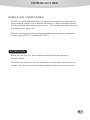
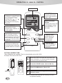
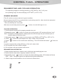
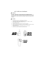
OPERATION MANUAL
READ THIS MANUAL CAREFULLY FOR INSTRUCTIONS ON CORRECT
INSTALLATION AND USAGE, AND READ ALL SAFEGUARDS.
~
‘
SECCION
EN ESPANOL
SECTION EN FRANÇAIS
Foreword
Congratulations on purchasing the MovinCool portable air conditioner. This manual explains
how to install and operate the MovinCool PC7 portable air conditioning unit. Please
read this operation manual thoroughly to familiarize yourself with the features of the unit and
to ensure years of reliable operation. You may also find it useful to keep this operation
manual on hand for reference.
Components and/or procedures are subject to change without prior notice.
Attention:
F
O
R
E
w
O
R
D
*
C
O
N
T
E
N
T
S
(1)
(2)
(3)
(4)
The unit is not intended for use by young children without supervision.
The plug should be accessible after installing the unit.
The unit should be installed in accordance with national wiring regulations/codes.
If the power cord is damaged, it must be replaced by the manufacturer or
a qualified service contractor. Contact your reseller for more information.
Contents
Instructions
Unit description and function
Operation of remote control
Use of control panel
Water drainage methods
Maintenance/service
Storage methods
Safety cautions
Troubleshooting
Installation
Window kit installation
1
2
4
5
6
9
10
11
12
13
14
INTRODUCTION
MOBILE AIR CONDITIONER
The PC7 is a small appliance,which can adjust the temperature and humidity in
a room making it easy to use in different occasions. It also has multiple modes,
including cooling, dehumidifying and fan only. This unit was designed to be used
in a family house, office, etc.
Other air conditioning solutions are recommended when the indoor temperature
0
0
0
0
is either below 65 F(17 C) or above 95 F(35 C) .
ATTENTION
Before you use your PC7 air conditioner, please read entire instruction
manual carefully.
This instruction manual is used for information only and does not form part of a
contract. We reserve the right to make technical changes without prior notice.
1
UNIT DESCRIPTION AND FUNCTION
FRONT
control panel
up/down air swinging fins
air oulet
left/right air swinging fins
handle
water tank
cable (power
caster
cord and plug)
BACK
evaporator air inlet grill
hot air outlet grill
condenser air inlet grill
2
UNIT DESCRIPTION AND FUNCTION
TIMER Button
SWING Button
Press this button to set the
timer for switch-on,switchoff or to stop the timer.
MODE
+
TIME
-
TIMER
FAN SPEED Button
Pressing this button
will activate/deactivate
auto-swing feature for
front louvers
FAN SPEED
COOL
HEAT
0
TIME Button
This button sets
the present time
and TIMER .
TEMP Button
Sets the room
temperature
SWING
F
MODE
ON
C
SET FAULT
POWER
MODE
HIGH MED LOW
0
DRY
FAN
TEMP
MODE Button
Pressing this button will
cycle through cooling,
drying, or fan-only mode
Pressing this button
will cycle through high,
middle, or low fan speed.
FAN SPEE
SWING
OFF
P
WATER FULL
POWER
Indication
light
WATER
FULL
indication
light
ON/OFF Button
Press this button will turn
the unit ON or OFF
Fan speed indicator
MODE
0peration mode
indicator
FAN SPEED
COOL
HIGH MED LOW
0
DRY
FAN
HEAT
0
SET FAULT
Displays preset temperature and failure codes
*When SET is displayed,the displayed digits
indicate the preset temperature
*When FAULT is displayed.the displayed digits
indicate the code of failures.
SWING
F
Louver indicator
ON
C
OFF
Timer Display
The displayed digits
indicate the remaining
time of on/off operation
3
OPERATION OF REMOTE CONTROL
Display screen
Temperature setting button
This button is used to set the
room temperature,Each
pressing of the"
" or "
"
button, will increase or
decreased the set temp by
0
10C or 1 F.
*
HEAT
o
F
ON/OFF Button
Pressing this button
will turn the machine
ON or OFF.
COOL DRY FAN
*
AM
PM
ON
OFF
H
FAN SPEED Button
Pressing this button
chooses high, medium, or
low fan speed.
ON/OFF
*
MODE selection
Button
Pressing this button will
cycle through cooling,
dehumidification, or
fan mode
*
TIMER button
Used to program unit timer.
When used together with the
"HOUR" button, the time setting
can be madewithin the range
of 1-12 hours, with the interval
of one hour.
FAN SP
EED
TIMER
Time Setting button
This button is used to set
the current time or the time
for timed switch-on or switchoff.
HOUR
MODE
HOLD
SWING
MIN
SWING button
Allows the louver
grills to oscillate
back and forth
automatically
HOLD button
Press this button to
lock or unlock the
keyboard.
SETTING CURRENT TIME
When batteries are inserted, Time is automatically set to AM 12:00
Example: Set time to AM 10:30
Press the CLK button.
CLK
ACL
HEAT
PM
Remove the back cover push the clock botton with
the tip of a ball pen, etc. The time indicator will flicker
and can be set to the present time.
2
Press the HOUR button. (Set to AM 10 )
3
Press the MIN button. (Set to 30)
4
Press the CLK botton again, then reattach
the back cover.
o
F
COOL DRY FAN
AM
1
ON
OFF
H
ON/OFF
*
*
FAN SPE
ED
TIM ER
Remove the
back cover
HOU R
MOD E
HOLD
SWI NG
MIN
NOTE Current time must be set correctly for timer
to operate correctly.
4
CONTROL PANEL OPERATION
DEHUMIDIFYING AND COOLING OPERATION
0
0
The operating ranges for cooling operation is 650F-860F(or 18 C-31 C) and
0
0
the operating range for dehumidifying is 650F-860F (or 18 C-31 C).
POWER SOURCE
*The AC socket must secured and in good condition
*Do not connect the PC7 to an outlet which is also being used for other electrical equipment.
*Fully insert plug into A/C outlet,
* The unit will beep for 2 seconds.
After two seconds has passed, press"
" button, the unit will begin to run.
COOLING OPERATION
1. Ensure that the drain tank is properly seated in the unit.
2.Repeatedly press "
" button to choose the cooling mode, LCD window will show "cool".
Note: During the cooling operation, always place the duct through an open window open to
exhaust warm air from the room.
0
0
3. Repeatedly press "
" button to set a proper room TEMP.at 650F-860F(or 18 FC-31 C).
4. Press "
" button to cycle between fan, high, middle, and low speed.
5. Press "
" button to turn on/off louver autoswing, The LCD window will show "
" when on.
MODE
+
-
NOTE:
In order to improve the cooling efficiency of the unit, ensure that:
a) Do not place the unit in direct sunlight
b) Do not place unit near another heat source.
DEHUMIDIFYING OPERATION
1. Keep windows and doors closed to aid in effectively dehumidifying the room.
2. Ensure that the drain tank is properly seated in the unit
3. Repeatedly press "
" button to choose the dehumidifying mode, LCD window will show
"DRY". Note: Fan speed cannot be adjusted during dehumidification.
4. When using as a dehumidifier, do not use the air exhaust duct.
MODE
5
USE OF CONTROL PANEL
TIME SET FUNCTION
To set start time, while the machine is turned off (but power supplied), press"
" button, the
ON ", press the TIME button to set the start time. The setting range
LCD window will show "
is 1-12 hours.
To set stop time, while the unit is operating locate and press "
" button,the LCD window
will show "
OFF ", press the TIME button again to set the stop time. The setting range
is 1-12 hours.
AUTO SWING FUNCTION
1.Auto swing function
Press"
" button, LCD window will show "
2.Press once again"
"button, the symbol "
louvers will stop swinging automatically.
-
Attention:
Press " + " and "
window will show "
disappear.
" and the louvers will swing automatically.
" in the LCD window will disappear, and the
" buttons together for more than two seconds to lockout the keys. LCD
" , press the two buttons together again to unlock the keys, " " will
WATER DRAINAGE METHODS
WATER DRAINAGE
When in cooling or dehumidifying mode, the condensate water will drain
into the tank. When the tank gets full, the WATER FULL indicator will flash.
As shown in the Fig. 1, 2 and 3 below, remove the condensate tank,
empty condensate tank and replace in original position
fig. 1
6
WATER DRAINAGE METHODS
fig. 2
fig. 3
CAUTION
1. When in cooling or dehumidifying mode, do not take out the condensate tank,or
the buzzer will sound, the compressor will stop, and the mode will change to FAN.
2. If you wish to empty the condensate water before the tank is full, first stop the
unit and wait 3 minutes before removing the condensate tank to prevent water
from spilling onto the floor.
3. There is a plastic tube with a plug located in the condensate tank area. Do not
remove the plug while the unit is operating.
7
MAINTENANCE/SERVICE
MAINTENANCE METHODS
*Unplug the unit before cleaning to prevent accidents caused by electric shock.
*
*Do not use chemical solvent ( like benzene, alcohol glazer) to clean the
surface of the unit. The surface of the PC7 will be scratched,damaged,and
plastic casing can become deformed.
AIR FILTER
If the air filter is dirty the unit's air flow volume may be affected. It is recommended
to clean filter once every two weeks.
Removing the air filter
1. Pull the air filter cover out, then up to remove the air filter cover from the unit.
2. Remove foam filter from the air filter cover.
grip
Clean
0
Wash the air filter by immersing it gently into warm (approximately 104 F) water
with a neutral detergent, rinse the filter of detergent and dry thoroughly in a
shaded area.
Mounting
1. Attach the filter to the filter cover using the attachment hooks on the inside
surface of the cover.
2. Place tabs at the bottom of the filter cover into mating holes in the case, push
filter back into its orginal position.
8
MAINTENANCE/SERVICE
CLEANING SURFACE
Clean the surface of the unit with a damp cloth, then dry using a duster or
similar type of lint-free cloth.
WATER TANK
1. Slowly pull condensate tank away from unit
2. Empty water, clean dirt with neutral detergent, wash and dry
3. Place condensate tank in original position
9
STORAGE METHODS
END OF SEASON OPERATIONS
1. Remove condensate drain tank from unit
2. Locate plastic tube as shown in Fig. 4. Remove plug and operate the unit in fan mode
for half a day or until tube is dry.
3. Turn unit off and disconnect the power cord from wall outlet
4. Secure power cord to unit.
5. Wrap the machine with the plastic bag and keep dry.
fig. 4
plastic duct
plug
fig. 5
10
SAFETY CAUTIONS
OCCASION
* Do not use the unit in a very narrow room with obstacles so as to avoid damaging
the unit when being moved
* Avoid using unit in direct sunlight to avoid panel surface color changing
* Do not use the unit in or near water.
* Do not use near gas appliances, fires, or near of flammable liquids.
POWER SOURCES
* Do not use with a damaged or improper A/C socket.
* When unplugging the unit, hold the power plug securely and pull it out carefully.
OTHERS
* Keep the unit 3 feet away from TV sets or radios to avoid the risk of electromagnetic
interference.
* Do not cover the air outlet to avoid overheating. Maintain 20" clearance from openings
SERIOUS CAUTION
*Do not tip over or incline the PC7, If the unit does tip over please unplug at once
and call your nearest reseller for further directions.
* Do not spray with insecticide or other chemicals as the plastic case may
be damaged.
11
TROUBLESHOOTING
Before seeking repair or service, please firstly check the following.
Trouble
Check
Air conditioner does
not operate at all
Action
Is there a power failure?
Is plug fully seated?
Is power fuse or switch off?
Is drain tank indicator is lit?
Is the water tank positioned correctly?
Is the SET TIME correct?
Cooling performance Is air inlet or outlet blocked?
Is there any other heat source in room?
insufficient?
Are air filters dirty?
Is SET TEMP. to high?
Is indoor fan speed set at low?
Excessive noise and
vibration
The refrigerant is flowing inside.
Is unit installed at an angle?
Normal.
Push the plug into the wall socket.
Change the fuse or switch on.
Empty water from the water
tank.
Fully seat the water tank into
the right position.
Correct SET TIME
Remove obstruction
Move unit away from heat
source
Clean the air filters
Set new temperature
Increase fan speed.
Normal operation
Place unit on a horizontal
floor
Is the voltage of the power source normal? Call qualified electrician
Keep outlet duct as strait as
(115V)
The machine starts
and stops frequently Is the air exhaust duct strait or bent?
possible
CAUTION
Unplug unit and discontinue use in the following cases. Contact your local reseller as soon
as possible.
1. The fuse and circuit breaker trip often.
2. The power cord is hot or the sleeve of the cord broken.
Self diagnosis function
The PC7 is equiped with self-diagnostic codes to assist users in troubleshooting the unit.
Please see the following chart below
12
Check code
Diagonosis of malfuncion
FAULT E8
Overheating
FAULT E3
Faulty coils
FAULT E2
Room temperature faults
FAULT E4
Units faults
INSTALLATION
Selection of installation lacation
Put the mobile air conditioner in a flat location where the air outlets cannot
be obstructed, place the unit no less than 20" away from a wall or other
obstacles.
5
(2 0cm
0
inc
h)
830mm(327 inch)
)
ch
in
3
7.
(1
375
inc mm(1
h)
2.8
44
0m
m
5
inc0cm(
h) 20
50c
m(
20
inc
h)
The air exhaust duct mounting method
1) Fix the square end of the exhaust dust to the exhaust terminal of the unit
2) Put the other end(discharge) to the nearest window
Note: Exhaust length is between 24 in - 71in,
When connecting duct, keep the air exhaust horizonal. Do not enlarge or
connect another discharge duct.
hot
hot air
air terminal
ferminal
exhaust (hot) air
heated exhaust air
duct attachment
duct tachm
window
window
exhaust
exhaust
airair
opening
opening
13
INSTALLATION
Recommended exhaust mounting is shown below (If mounting in the wall,the
height of the hole should be 16in ~ 51in)
fig. 23
(51 inch)
(16 inch)
If the air exhaust requires bends, see diagrams below.
(20 inch)
(24 inch)
(20 inch)
14
INSTALLATION
See diagram below for incorrect exhaust mounting (Air exhaust bends too large)
Window Kit Installation
Your window kit has been designed to fit most standard "vertical" and "horizontal" windows
However, it may be necessary for you to modify some aspects of the window panels for
certain types of windows. Please refer to Fig. 24 & Fig. 24a for minimum and maximum
window openings.
CAUTION: WINDOW KIT DOES NOT PREVENT UNAUTHORIZED ACESSS
Fig.24a
Fig.24
Fig.24
Water Tank Safety Feature
This unit is equipped with a fail-safe switch which turns the unit off water in the event the water tank
overflows and/or is FULL with water. The unit will signal 8 BEEPS and the WATER FULL indicator
light will flash red continuously until the water tank is correctly positioned and/or emptied.
NOTE:
The fan motor will continue to operate under this condition. No cooling or dehumidifying
will occur until the tank is emptied and/or correctly installed (The compressor may cycle through
internal time delay).
15
INSTALLATION
Installation Accessories Fig. 25
Description
Flexible exhaust hose with adapters...........3/set
streches from 19 1/2" (50 cm) up to 78 3/4"(200cm)
Fig. 25
Window exhaust adapter (flat mouth )........1pc
Adjustable window slider kit......................2/set
from 26 5/8" (67.5 cm) up to
48 3/8" (123 cm)
Drain hose connector...............................1 pc
For continuous drain option (hose not included)
SPECIAL NOTE: Drain hose extension is
not included with this unit and can be purchased
through a local Hardware Store.
For the continous drainage:
1. Take off the plug of the drainage tube (see
illustration)
2. Extend the tube outside the unit as indicated.
Note: The drain hose cannot exceed the height
of the the drain hose opening or unit will overflow
Power roll wire clasp
Secure power cord to unit by using the two
located on the back of the panel
16
I
AFCI / LCDI Power Cord Manual
! WARNING
The AFCI / LCDI device is a non-serviceable part. Attempting to open the
device may expose the user to hazardous electric shock, and voids any warranties
and performance claims. Manufacturer’s liability is limited to the replacement of
the device.
! CAUTION
1.
2.
3.
4.
5.
6.
7.
Read manual for proper use and handling of this device.
Press “RESET” button before starting the A/C unit. Press “TEST” to check
function then “RESET” again. Start the A/C unit.
Do not immerse in water
This device must only be plugged on appropriate wall outlet.
In the event that this device trip, the cause of the malfunction should be corrected
before any further use.
Using the device beyond recommended voltage poses risk to users
Reset and Test button orientation may differ by model
“TEST” Button
“RESET” Button
“TEST” Button
“RESET” Button
RESET Button
TEST Button