1
ATARI HARD DISK
FILE SYSTEMS
REFERENCE GUIDE
Jean Louis-Guérin (DrCoolZic)
Version 1.2b September 2014
Table of Content
How to Read this Document ............................................................................................... 5
PART I – ATARI HARD DISK FILE SYSTEM PARTITIONING GUIDE............................... 7
Chapter 1. Partitioning Information ................................................................................. 8
1.1
1.2
1.3
Hardware Consideration .......................................................................................................... 8
Hard Disk File System Primer ................................................................................................. 8
Preparing a Drive ..................................................................................................................... 9
Chapter 2.
Types of Partition used on Atari ..................................................................10
2.1
TOS Partitions ....................................................................................................................... 10
2.2
DOS/FAT Partitions ............................................................................................................... 10
2.2.1 Type and Limit of DOS/FAT Partitions .............................................................................. 10
2.2.2 Small DOS/FAT Partitions ................................................................................................. 10
2.2.3 Large DOS/FAT Partitions ................................................................................................. 10
2.2.4 Huge DOS/FAT Partitions ................................................................................................. 11
2.3
TOS&DOS Partitions ............................................................................................................. 11
2.4
Notes on Creating and Installing Partitions ........................................................................... 11
2.4.1 Creating TOS Partitions ..................................................................................................... 11
2.4.2 Creating DOS partitions ..................................................................................................... 12
2.4.3 Creating TOS&DOS partitions ........................................................................................... 12
2.4.4 Creating Bootable Partitions .............................................................................................. 12
2.4.5 Installing Disk Partitions on the Atari Desktop ................................................................... 12
Chapter 3.
TOS/GEMDOS Limitations ............................................................................13
3.1
TOS and Long File Name (LFN)............................................................................................ 13
3.2
TOS Maximum Path Depth .................................................................................................... 14
3.3
TOS Maximum Number of Folders ........................................................................................ 14
3.4
TOS Maximum number of files .............................................................................................. 15
3.5
TOS Maximum number of partitions ...................................................................................... 15
3.6
Discussion of OS Pool (from Rainbow TOS release notes) .................................................. 15
3.7
TOS Version Specific Limitations .......................................................................................... 16
3.7.1 ROM TOS 1.0 - 520ST and 1040ST ................................................................................. 16
3.7.2 MEGA TOS 1.02 - 520ST, 1040ST, Mega 2/4 .................................................................. 17
3.7.3 Rainbow TOS 1.04 – 520ST, 1040ST, Mega 2/4 .............................................................. 17
3.7.4 STE TOS 1.06 - 1040STE and 520STE ............................................................................ 17
3.7.5 STE TOS 1.62 - 520STE, 1040STE .................................................................................. 17
3.7.6 Mega STE TOS 2.05 - Mega STE ..................................................................................... 17
3.7.7 TT TOS 3.01 - TT030 ........................................................................................................ 17
3.7.8 TT TOS 3.05 - TT030 ........................................................................................................ 17
3.7.9 Falcon TOS 4.X ................................................................................................................. 17
Chapter 4.
Atari Hard Disk Drivers Packages ................................................................18
4.1
Hardware Configurations Tested ........................................................................................... 18
4.2
Information on Removable Drive ........................................................................................... 18
4.2.1 Disk Change Support......................................................................................................... 18
4.2.2 Specification of the Maximum Logical Sector Size ............................................................ 18
4.2.3 Number of Partitions on a Card ......................................................................................... 18
4.3
Things to check before you start ........................................................................................... 18
4.3.1 Satan device ...................................................................................................................... 18
4.3.2 UltraSatan device .............................................................................................................. 18
4.4
HDDRIVER 9.02 Driver Package .......................................................................................... 19
4.4.1 Partitioning a drive ............................................................................................................. 19
4.4.2 Enabling and Disabling Auto boot ..................................................................................... 20
4.4.3 Configuring the HDDRIVER Hard Disk Driver ................................................................... 21
4.4.4 Accessing DOS Partitions ................................................................................................. 21
4.4.5 Accessing TOS & Windows Partitions ............................................................................... 21
4.4.6 Special Care to boot from device other than ACSI ID0 ..................................................... 21
4.5
PPDRIVER 1.0 Driver Package ............................................................................................. 22
4.5.1 Partitioning a drive ............................................................................................................. 22
4.5.2 Installing the Auto boot Driver ........................................................................................... 23
4.5.3 Removable Medium Drive Support .................................................................................... 23
© Jean Louis-Guérin – V1.2a – September 2014
Page 2 / 69
4.5.4 Accessing DOS Partitions ................................................................................................. 23
4.5.5 Accessing TOS&DOS Partitions ........................................................................................ 23
4.5.6 Driver usage ...................................................................................................................... 23
4.6
ICD AdSCSI Pro 6.5.5 Driver Package ................................................................................. 24
4.6.1 Partitioning a drive ............................................................................................................. 24
4.6.2 Enabling and Disabling Auto boot ..................................................................................... 26
4.6.3 Configuring the AdSCSI Hard Disk Driver ......................................................................... 27
4.6.4 Removable Medium Drive Support .................................................................................... 27
4.6.5 Accessing DOS Partitions with ICD ................................................................................... 27
4.6.6 Accessing TOS&DOS Partitions ........................................................................................ 27
4.7
CBHD 5.0.2 Driver Package .................................................................................................. 28
4.7.1 Partitioning a drive ............................................................................................................. 28
4.7.2 Enabling Auto boot ............................................................................................................ 28
4.7.3 Configuring the CBHD Hard Disk Driver............................................................................ 29
4.7.4 Removable Medium Drive Support .................................................................................... 29
4.7.5 Accessing DOS Partitions ................................................................................................. 29
4.7.6 Accessing TOS&DOS Partitions ........................................................................................ 29
4.8
SCSITools 6.5.2, and AHDI Driver Packages ....................................................................... 29
4.9
Which Hard Disk Driver Should I use .................................................................................... 30
4.9.1 Hard Disk Driver Summary Table ...................................................................................... 30
Chapter 5.
PC Utilities .....................................................................................................31
5.1
Accessing Multiple Partitions from SD Cards ........................................................................ 31
5.1.1 32 bits Windows - Hitachi Microfilter .................................................................................. 31
5.1.2 64 bits Windows – Diskmod from Karyonix ....................................................................... 31
5.1.3 64 bits Windows – Access through virtual 32 bits machine............................................... 31
5.2
Creating DOS Partitions on a PC .......................................................................................... 32
5.3
Working with Disk Images ..................................................................................................... 33
5.4
Partition Table Editor ............................................................................................................. 34
5.5
PC File Transfer Tools ........................................................................................................... 34
Chapter 6.
Atari Utilities ..................................................................................................35
6.1
BigDOS .................................................................................................................................. 35
6.1.1 Features ............................................................................................................................. 35
6.1.2 Installing BigDOS............................................................................................................... 35
6.1.3 BigDOS Sundries ............................................................................................................... 35
6.2
FOLDRXXX Utility.................................................................................................................. 36
6.3
TOS14FIX Utility .................................................................................................................... 36
6.4
POOLFIX3 Utility ................................................................................................................... 36
6.5
CACHEXXX Utility ................................................................................................................. 36
6.6
STE_FIX Utility ...................................................................................................................... 36
Chapter 7. File System Problems and Solutions ...........................................................37
PART II – ATARI HARD DISK FILE SYSTEMS TECHNICAL INFORMATION ...................38
Chapter 8. Hard Disk Presentation .................................................................................39
8.1
Hard Disk Primer ................................................................................................................... 39
8.1.1 CHS Format ....................................................................................................................... 39
8.1.2 LBA Format........................................................................................................................ 39
8.1.3 Conversion between CHS and LBA .................................................................................. 39
8.2
Hard Disk Preparation Steps ................................................................................................. 40
8.3
TOS Partition Size ................................................................................................................. 41
8.4
DOS/FAT Partition Type and Size ......................................................................................... 41
8.5
TOS&DOS Partition Size ....................................................................................................... 41
Chapter 9.
Information about TOS Partitions ................................................................42
9.1
TOS Hard Disk Layout ........................................................................................................... 42
9.2
TOS Root Sector ................................................................................................................... 42
9.3
TOS Standard Partition ......................................................................................................... 43
9.3.1 Regular Partition (GEM) Limits .......................................................................................... 43
9.3.2 Big Partition (BGM) Limits ................................................................................................. 43
9.3.3 Example of layout with TOS standard partitions ............................................................... 44
9.4
TOS Extended Partition ......................................................................................................... 44
© Jean Louis-Guérin – V1.2a – September 2014
Page 3 / 69
9.4.1 TOS Extended Root Sector ............................................................................................... 44
9.4.2 Example of layout with TOS extended partitions ............................................................... 45
9.5
TOS Partition Structures ........................................................................................................ 46
9.5.1 TOS Boot sector ................................................................................................................ 46
9.5.2 TOS File Allocation Table .................................................................................................. 47
9.5.3 TOS Root Directory ........................................................................................................... 47
9.5.4 Size and Position of the TOS Partition Structures ............................................................. 49
9.5.5 Computing Boot Sector values from User Inputs .............................................................. 49
9.6
TOS Boot Sequence .............................................................................................................. 50
Chapter 10.
Information about DOS/FAT Partitions ....................................................51
10.1 DOS/FAT File System Information ........................................................................................ 51
10.2 DOS/FAT Hard Disk Layout .................................................................................................. 51
10.3 DOS/FAT Master Boot Record (MBR)................................................................................... 51
10.4 DOS/FAT Primary Partition ................................................................................................... 52
10.4.1 Example of layout with DOS/FAT standard partitions ....................................................... 53
10.5 DOS/FAT Extended Partition ................................................................................................. 53
10.5.1 Extended Master Boot Record (EMBR)............................................................................. 53
10.5.2 Example of layout with DOS/FAT extended partitions ...................................................... 55
10.6 DOS/FAT Partition Structures ............................................................................................... 55
10.6.1 DOS/FAT Boot sector ........................................................................................................ 55
10.6.2 FS Information Sector ........................................................................................................ 57
10.6.3 DOS/FAT File Allocation Table .......................................................................................... 57
10.6.4 DOS/FAT Directory Table .................................................................................................. 58
10.6.5 Position of the Structures in a DOS Partition .................................................................... 60
10.6.6 DOS/FAT Long file names ................................................................................................. 60
10.7 DOS/Windows Boot Sequence.............................................................................................. 62
Chapter 11.
Information about TOS&DOS Partitions...................................................63
11.1 TOS&DOS Hard Disk Layout ................................................................................................ 63
11.2 TOS&DOS MBR / EMBR ....................................................................................................... 64
11.2.1 PPDRIVER 1.0 MBR / EMBR ............................................................................................ 64
11.2.2 HDDRIVER 9.02 MBR / EMBR ......................................................................................... 65
11.3 TOS&DOS Partition Structure ............................................................................................... 67
11.3.1 TOS&DOS Boot Sector ..................................................................................................... 67
11.3.2 TOS&DOS FAT, Directory Table, and Boot Sequence ..................................................... 68
References ..........................................................................................................................69
History .................................................................................................................................69
© Jean Louis-Guérin – V1.2a – September 2014
Page 4 / 69
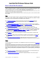
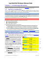
How to Read this Document
I have created this document as a reference manual that I use personally to find specific information
related to usage of Hard Disks. It provides technical information about the different File Systems used
on the Atari platform as well as a practical short guide for using and partitioning Hard Disks on Atari
(more specifically SD Cards connected to Satan / UltraSatan / CosmosEx devices).
Therefore most probably you do not want to read this document from front to back. This is why I have
organized it so you can quickly access information.
The first part contains practical information while the second part goes into more technical details
when needed.
Part I
The first part of the document focuses on practical information and procedures for partitioning Atari
Hard Disks. It also contains a basic presentation of the Atari and DOS File systems to better
understand the choices and limitations of the different types of partitions.
The Partitioning Information chapter provides basic information about partitioning disks and
minimum knowledge you should have about Atari file system. It is short and therefore it is a
recommended reading.
The Types of Partition used on Atari Chapter gives an overview of the different types of partition
used on Atari: TOS partitions, DOS/FAT partitions, and TOS&DOS partitions. It also provides some
Notes on Creating and Installing Partitions on Atari Desktop.
The TOS/GEMDOS Limitations chapter provides information about the limitations of
TOS/GEMDOS and is good to read if you run into mysterious problems using your hard disk.
The Atari Hard Disk Drivers Packages chapter contains simplified guides for usage of several hard
disk driver packages (HDDRIVER, PPDRIVER, AdSCSI, and CBHD) with Satan, UltraSatan, and
CosmosEx devices. Which Hard Disk Driver Should I use help you select a hard disk driver
package for Satan, UltraSatan, and CosmosEx devices.
The PC Utilities chapter review several programs, available on the PC platform, related to Hard
Disk usage.
The Atari Utilities chapter review several programs, available on the Atari platform, related to Hard
Disk usage and File System related bug fix. It also contains a short presentation of the BigDOS
program.
The File System Problems and Solutions chapter describes several commonly encountered
problems and their solutions. It is recommended reading when hard disks do not work as expected.
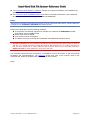
Part II
Technical details about TOS, DOS/FAT, and TOS&DOS file systems are presented in the second part
of this document.
The goal of the second part of this document is thus to provide in-depth technical information about
Atari hard disks partitioning (layout). For that matter I describe in detail the TOS File System as well as
the DOS/FAT File System as both of them are used on the Atari platform. The DOS/FAT File System
study is limited to what is useful in the context of the Atari platform. I also describe the TOS&DOS File
system used by PPDRIVER and HDDRIVER. Examples of File System partitioning are analyzed
deeply.
The Hard Disk Presentation chapter provides a high level presentation of hard disk partitioning as
well as practical partitions limits for the different type of file system.
The Information about TOS Partitions provides an in-depth presentation of the TOS file system.
© Jean Louis-Guérin – V1.2a – September 2014
Page 5 / 69
The Information about DOS/FAT Partitions provides an in-depth presentation of the DOS/FAT file
system.
The Information about TOS&DOS Partitions provides an in-depth presentation of the TOS&DOS
file system as created and used by PPDRIVER and HDDRIVER.
Notes:
Although the information presented here applies to generic ASCI/SCSI Hard Drives, specific details are
provided for the CosmosEx, UltraSatan and Satan Devices.
Note that the Satan Drive has the following limitations:
The maximum size officially supported is 1GB SD card. However the PPDRIVER hard disk
driver allows usage of 2GB SD Card.
SDHC cards are not handled,
Only one SD card can be plugged,
And Satan Drive only works with the PPDRIVER and HDDRIVER hard disk drivers.
A word of caution: All the procedures described in this document have been tested on Atari ST
and STE. To a certain extent they should also apply to Atari Mega ST(e) / TT / Falcon. However no
test has been performed on these platforms and therefore some of the described procedures
might not work on these platforms. Use at your own risk!
The information presented here is based on a compilation of many documents as well as personal
knowledge and experimentations. The reference section lists most of the sources used in this
document and, whenever possible, links to the originals are provided.
Enjoy!
© Jean Louis-Guérin – V1.2a – September 2014
Page 6 / 69
PART I – ATARI HARD DISK
FILE SYSTEM
PARTITIONING GUIDE
© Jean Louis-Guérin – V1.2a – September 2014
Page 7 / 69
Chapter 1. Partitioning Information
This section provides basic information about Atari & PC hard disk partitioning (layout). For technical
details on the TOS and FAT file systems please refer to the second part of this document.
1.1
Hardware Consideration
Atari ST / STE computers provide an external DMA bus connection through the Atari Computer
System Interface (ASCI) connector. This bus is very similar (simplified version) to the standard SCSI
bus and allows connection of different type of devices such as hard disks.
Atari Mega STe, TT, Falcon computers provide direct support for IDE and/or SCSI Hard disk buses.
The disk drives are connected to Atari ST ASCI bus through a Host Adapter. The host adapter acts
as an interface between the Atari DMA bus and the drive controller. For example a SCSI disk can be
connected to the ASCI bus through an ICD AdSCSI Plus host adapter, or an SD card can be
accessed through a CosmosEx Device that acts as a host adapter.
When several devices are connected to an ASCI bus you must assign a unique ID to each of them.
The maximum usable size of a hard disk is limited by several factors:
The size of the hard disk itself,
The Hard Disk Driver software,
The File System limitations, and
The Host Adapter capability.
We can differentiate two families of host adapters:
The host adapters that strictly implement the ASCI-AHDI command set (corresponding to the
SCSI group 0 command set). With this type of host adapter the maximum size of the drive is
limited to 1GB (2^11 sectors of 512 bytes). For examples: The ICD Link I, the Satan Drive.
The host adapters that implement the ICD extended command set (corresponding to the SCSI
group 1 command set). With this type of adapter the maximum size of the drive is lifted to 2TB
(2^32 sectors of 512 bytes). For examples: The ICD Link II, the CosmosEx device.
To access drives bigger than 1GB you need to have a host adapter and a hard disk driver that both
understand the ICD extended command set.
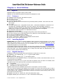
1.2
Hard Disk File System Primer
The Atari ST/STE platform uses natively the TOS file system as defined in the Atari AHDI 3.0
document. The PC platform uses a wide variety of file systems but in this document we will only look
at the DOS/FAT file system that can be used on an Atari platform.
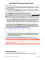
While both of these file systems look similar they
are different. Therefore we need to have a basic
comprehension of both file systems in order to
appreciate their limitations and incompatibilities.
Detailed technical information on TOS, DOS file
systems can be found in Part II of this document.
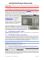
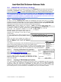
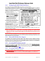
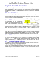
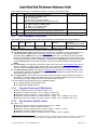
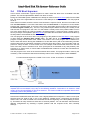
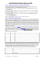
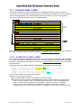
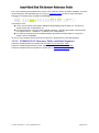
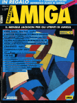
The picture on the right shows an example of
layout for a partitioned and initialized hard disk
with three primary partitions and an extended
partition that contains two primary partitions (see
9.4.2 for more details).
An already partitioned and initialized disk is
composed of:
The Reserved area: containing the Master
Boot Record (MBR), located at physical
sector 0, and followed by reserved sectors.
The MBR defines the number of partitions
and their positions on the disk.
The Partition area: containing from one to 4 partitions (primary or extended) with the actual data.
© Jean Louis-Guérin – V1.2a – September 2014
Page 8 / 69
There are two types of partitions:
The Primary partition contains several control structures and the actual file and directory data.
The Extended partition is a special kind of partition which is itself subdivided into one or several
primary (aka as secondary) partitions allowing a number of partitions superior to 4 on the disk.
A primary partition contains:
The Boot Sector located at the very beginning of the partition (logical sector 0). It contains an
important area called the BPB (BIOS Parameter Block) that gives basic file system information.
Frequently it also contains the boot loader code.
The FATs are maps of the Data, indicating which clusters are used by files and directories.
The Root Directory stores information about the files and directories.
The Data Region is where the actual file and directory data is stored.
Most of the problems of compatibility between the TOS and FAT file systems are located in the BPB
area of the Boot Sector. Following is a description of the critical parameters of the BPB:
Two important parameters in the BPB are the number of bytes per sector (BPS) and the number of
sectors per cluster (SPC). They are interpreted differently by TOS and DOS/FAT but together they
define the notion of Logical Sector1. On a TOS file system a Logical Sector = BPS and can range
from 1024 to 81922 Bytes and the SPC is always equal to 2. On a DOS/FAT file system a Logical
Sector = BPS * SPC. The BPS is always 512 bytes but the SPC can range from 2 to 128 resulting
to logical sector of 1024 to 65536 Bytes. Therefore we can see that the two file systems use a
different scheme to define logical sectors bigger than 512 bytes. For example a logical sector of
8192 bytes is achieved with a BPS = 8192 and a SPC = 2 on the TOS file system. The same 8192
bytes logical sector is achieved with a BPS = 512 and a SPC = 16 on the DOS file system.
Another important parameter in the BPB is the total number of sectors. On a TOS file system this
number is stored as a 16-bit quantity (NSECTS parameter). This results in a maximum size of
512MB (2^16 * 8192 bytes) for a TOS partition3. On DOS/FAT file system the number of sectors
can be stored as a 32-bit quantity (HSECTS parameter) allowing definition of partitions up to 2TB.
For technical details look at TOS Boot sector and DOS/FAT Boot sector
1.3
Preparing a Drive
A drive needs to be “prepared” before it can be used to store data. With modern drive, this is done in
two steps:
The first step is called partitioning:
Hard drives are divided into smaller logical drive units called partitions. In this way a single
hard drive can appear to be two or more drives to the OS. Besides simply keeping drive sizes
under the file system size limits, dividing a drive also allows partitions to be used for specific
purposes, keeping the drive organized.
The second step is called high-level formatting (also referred as formatting or initialization4):
This is the process of creating and initializing the basic disk's control structures: namely the
Boot Sector, the FATs, and the Root Directory as described in the previous section.
Note: On old hard disks you also had to format them (also referred as low level formatting)
before partitioning. Low level formatting allows the magnetic medium on the surfaces to be divided
into tracks containing numbered sectors that the controller can find. With “modern” SCSI / IDE
drives and with drives using SD cards this operation is not required anymore and therefore is not
described in this document.
1
Note that the term logical sector is used differently on Atari and PC platforms.
32768 for TOS4.0 on Falcon (but officially supported only 16384)
3
For TOS < 1.04 max partition size = 256MB (215 * 8192), and for TOS 4.x max partition size = 2GB (216 * 32768).
4
The term “Formatting” is used in PC environment while the term “Initialization” is often used in Atari environment.
2
© Jean Louis-Guérin – V1.2a – September 2014
Page 9 / 69
Chapter 2. Types of Partition used on Atari
Before we detail the partitioning procedures for several hard disk drivers, we need to understand the
basic types of partitions used on Atari and their limitations.
2.1
TOS Partitions
This is the “native” type of partition used an Atari as described in the Atari AHDI documentation. It is
supported by all the Atari hard disk drivers and in fact some of the old drivers only support this type of
partition. This is the type of partitions that you want to use on Atari unless you plan to use the media
(HD or SD card) to transfer data between Atari and PC computers.
Remember that the maximum size for a partition depends on: the hard disk size, the hard disk driver,
the host adapter capability, and the TOS version.
With recent hard disk driver and host adapters (that is supporting the ICD extended commands set)
the maximum size for a partition is:
Up to 256MB for TOS < 1.04
Up to 512MB for TOS ≥ 1.04
Up to 2GB for TOS ≥ 4.x (Falcon)
Contrary to widely spread belief, the boot partition (usually the first partition on disk) can be a big
partition (BGM) and therefore can use the maximum size supported by the TOS (For example 512MB
for 1.04 ≤ TOS < 4.x). The actual limitation to 32MB (GEM) for the boot partition does not come from
TOS/GEMDOS file system but from some hard disk driver. Only very old hard disk driver like SCSITools
and AHDI hard disk driver exhibit this limitation.
2.2
2.2.1
DOS/FAT Partitions
Type and Limit of DOS/FAT Partitions
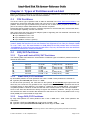
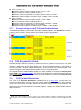
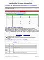
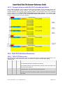
The following table summarizes the characteristics of different types of DOS/FAT partitions that are of
interest for Atari users:
Partition Type
01
04
05
06
0E
0F
0B
0C
2.2.2
Fdisk
PRI DOS
PRI DOS
EXT DOS
PRI DOS
PRI DOS
EXT DOS
PRI DOS
EXT DOS
Size
0-15 MB
16-32 MB
0-2 GB
32 MB-2 GB
32 MB-2 GB
0-2 GB
512 MB - 2 TB
512 MB - 2 TB
Fat Type
12 bits (FAT12)
16 bits (FAT16A)
n/a
16 bits (FAT16B)
16 bits (FAT16B)
n/a
32 bits (FAT32)
32 bits (FAT32)
Version
MS-DOS 2.0
MS-DOS 3.0
MS-DOS 3.3
MS-DOS 4.0
Windows 955
Windows 95
OSR2
OSR2
Small DOS/FAT Partitions
By Small DOS partition we mean partitions with a size < 32MB. These partitions are referred as:
Type $04 (aka FAT-16A) with a size of < 32MB
As we have seen previously, the TOS and FAT file systems do not handle large logical sector the
same way. As a result it is only possible to use a logical sectors size of 1024 for partitions that can be
accessed directly on both platforms. This results to a maximum size of 32MB (65536 * 512 bytes) for
compatible partitions. However we will see later that some solutions exist to overcome this limitation.
Some of the Atari hard disk drivers directly recognize the DOS/FAT partitions. This type of partition
can therefore be useful to transfer data between an Atari and a PC. But as the partition size is very
small (32MB) it is not well suited for large disks.
2.2.3
Large DOS/FAT Partitions
By large DOS partition we mean partitions with a size ≥ 32MB and < 2GB. These partitions are
referred as:
Type $06 or $0E (aka FAT-16B) with a size range of 32MB – 2GB
Type $05 or $0F (aka Extended FAT-16B) with a size range of 32MB – 2GB
5
Type 0x0E and 0x0F forces usage of LBA addressing instead of CHS addressing (recognized by Windows 95 and above).
© Jean Louis-Guérin – V1.2a – September 2014
Page 10 / 69
As we have seen due to the constraints imposed by the TOS file systems and the DOS file systems it
seems that it is only possible to access Small FAT16A (≤ 32 MB) DOS partitions with an Atari.
However the BigDOS freeware allow access to Large DOS partitions. BigDOS works with several
hard disk driver for example HDDRIVER and CBHD. But unfortunately it does not work with some
other drivers like the ICD AdSCSI or PPDRIVER hard disk driver. See BigDOS section for more
information.
We have seen most of the problems related to the file system (for example the fix value of SPC=2)
come from code inside GEMDOS. As BigDOS replaces GEMDOS at boot time it allows to remove
many of these limitations. More specifically it permits the support of SPC values of up to 64, and the
maximum number of sectors is specified as a 32-bit value (instead of the TOS 16-bit value). Therefore
BigDOS can deal with more than 65536 big logical sectors and this removes the 32MB limitation.
For example using BigDOS and HDDRIVER it is possible to create several 2GB partitions on an 8GB
SD Card and to successfully transfer data from Atari and PC platforms.
2.2.4
Huge DOS/FAT Partitions
By Huge DOS partition we mean partitions with a size ≥ 2GB. These partitions are referred as:
Type $0B (aka FAT32) with a size range of 512MB – 2TB
Type $0C (aka Extended FAT32) with a size range of 512MB – 2TB
It is not possible to directly access huge DOS/FAT partitions on Atari (even when using BigDOS) with
the Atari hard disk drivers discussed in this document.
You should know that there are some solutions to access Huge DOS partitions on an Atari (for
example by using Mint) but they are not covered in this document.
2.3
TOS&DOS Partitions
The PPDRIVER and HDDRIVER hard disk drivers described in this document use a hybrid type of
partition called TOS&DOS (or TOS&Windows) partitions. These partitions are processed by Windows
PC computers as DOS/FAT partitions and by Atari computers as TOS partitions. For each TOS&DOS
partition two boot sectors are written: one for the DOS file system and one for the TOS file system.
The maximum size of a TOS&DOS partitions follows the TOS file system limitation (for example
512MB for TOS ≥ 1.04). There is no standard for this type of partition and even though HDDRIVER
and PPDRIVER packages use similar technique the two drivers are in practice incompatible.
TOS&DOS partitions are accessible on both Atari and PC platforms, they can be made bootable on
Atari, and they can have a large size for example up to 512MB for TOS 1.04. Therefore they are well
suited for data transfer between Atari and PC computers using SD cards plugged for example into
CosmosEx device.
IMPORTANT WARNING: A TOS&DOS partition is not a regular TOS partition and therefore it should
only be accessed on the Atari with the matching hard disk driver. For example using the ICD
AdSCSI hard disk driver gives the impression to access TOS&DOS partitions correctly (it even
report correctly the size) but if you try to read beyond the first 32MB of the partition you will get
incorrect results and even worse if you try to write you will definitively corrupt the partition.
2.4
2.4.1
Notes on Creating and Installing Partitions
Creating TOS Partitions
As we will see later all the Atari Hard Disk driver packages provide a utility that to create TOS
partitions. It is interesting to note that whatever hard disk driver utility you use the resulting TOS
partitions follow the AHDI standard and therefore will be compatibles with all HD drivers. Therefore
you can use the partitioning tool from one package and use the resulting TOS partitioned drive with
any other Atari hard disk driver.
© Jean Louis-Guérin – V1.2a – September 2014
Page 11 / 69
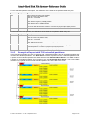
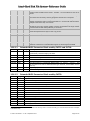
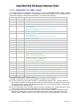
The following table shows the minimum logical sector size required for specific partition sizes:
Partition Size6
Up to 32MB
32MB – 64MB
64 MB – 128MB
128 MB – 256MB
256MB – 512MB
512MB – 2GB7
Logical Sector Size
512
1024
2048
4096
8192
32768
During partitioning you only need to specify the size of the partitions you want to create and the driver
will compute for you the optimum logical sector size. However it is possible in some cases to modify
this size during the “initialize” command. In that case you have to make sure that you specify a value
superior or equal to the minimum value presented in the table above.
2.4.2
Creating DOS partitions
Some hard disk drivers support creating DOS/FAT partitions. However it is usually easier and safer to
create the DOS partitions directly on a PC. This is covered in Creating FAT Partitions on a PC.
2.4.3
Creating TOS&DOS partitions
TOS&DOS partitions can only be created by PPDRIVER and HDDRIVER packages. Only use
TOS&DOS partitions with the matching driver (as they are not compatible) and never use them with
any other driver (see § 2.3 for important warning).
2.4.4
Creating Bootable Partitions
Most probably you also want to define at least one bootable partition on a drive so that the Atari can
be started from the hard disk without a diskette. The procedure to render a partition bootable is
described, for each reviewed hard disk driver, in the next chapter. For detailed information look at TOS
Boot Sequence in Part II of this document.
2.4.5
Installing Disk Partitions on the Atari Desktop
After a drive has been partitioned you need to add a drive icon on the Atari desktop for each of the
partitions. Without these drive icons, the partitions will not be accessible from the desktop.
The procedure is the following:
On the Atari desktop, click on the icon associated with the floppy disk A and choose Install Disk
Drive... from the Options drop-down menu.
Change the drive identifier letter to “C” for example and the Icon label name to whatever
name to you want to see on the Atari desktop for this partition.
Click on Install, then move the new icon to the position you want it on the Atari desktop.
Repeat this procedure for each of the partitions on the drive(s), incrementing the Drive
Identifier letter each time.
Make sure you use capital letter (for example C) for the drive identifier. Otherwise the system will
think you are specifying a cartridge and the hard drive partition will not be accessible.
Once you have added drive icons for all the partitions of all the hard disk drives, you can save
the desktop by selecting Save Desktop command from the Options menu. This will write the
DESKTOP.INF file on the boot drive. This file is used, when the computer is booted, to retrieve
the defined environment (including disk drive icons).
6
7
Partition size is given for TOS ≥ 1.04. Prior to this version the maximum partition size should be divided by 2
Only supported in TOS 4.0. Officially only sector size of 16384 is supported (maximum size 1GB)
© Jean Louis-Guérin – V1.2a – September 2014
Page 12 / 69
Chapter 3. TOS/GEMDOS Limitations
We have seen that the file system used to partition a hard disk introduces some limitation. On top of
that the TOS/GEMDOS OS adds more limitations which are different for different versions of TOS and
GEMDOS. The following sections present some of these limitations.
3.1
TOS and Long File Name (LFN)
On Atari the file names recognized by TOS/GEMDOS system are limited to 8+3 Characters. Before
transferring files from a PC to an Atari you have to make sure that all files and folders names are
following the 8+3 specification and contains only capital letters. A PC tool like Total Commander can
help you for that matter. If you do not follow these two constraints you may get unexpected
behaviors.
Of course this problem only applies to the DOS or TOS&DOS partitions that are accessible on a PC
as it is not possible to create such files on a TOS system. The long file names on FAT16 partitions are
stored using special invalid entries in the directory table that TOS do not understand, and therefore do
not handle correctly.
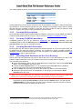
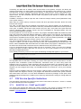
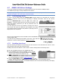
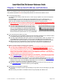
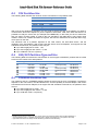
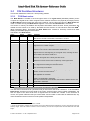
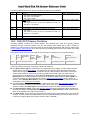
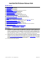
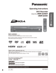
If a partition contains files with long file name watch out for the
following problems:
If you ask for the size of a folder (or drive) containing LFN, with
for example the desktop “File Info …” you will get a large and
erroneous number for the size of a tree. The number can get
so huge (resulting in an overflow) that invalid character will
show up in the size field (see picture - Taille is Size in French).
If a program tries to copy a directory that contains LFN it will
probably complains of not being able to access files with
strange name and terminates. This is the case for example if
you try to copy this kind of directory by dragging and dropping
it from the desktop. In this case the copy is done partially with
a very brief error message and the copy operation terminates prematurely.
If you delete a file with a long file name the directory structure will get corrupted (it will contains
invalid entries left over that won’t be understood even by Windows).
Note that BigDOS fix the problem of LFN for DOS/FAT or TOS&DOS partitions. You won’t be able to
see Long File Names on the Atari but they will be handled correctly if BigDOS has been loaded.
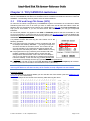
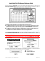
Technical details:
If you are interested by technical details you can read the rest of this section (see also DOS/FAT Long
file names for more information)
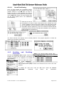
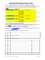
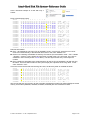
Here is an example of the content of the directory table with long file name:
Offset
0002A000
0002A010
0002A020
0002A030
0002A040
0002A050
0002A060
0002A070
0002A080
0002A090
0002A020
0002A0B0
0002A0C0
0002A0D0
0002A0E0
0002A0F0
0002A100
0002A110
0002A120
0002A130
0002A140
0
53
8D
44
FF
03
47
02
4F
01
53
54
8D
53
8D
42
FF
01
4F
4C
8D
00
1
48
3B
54
FF
52
00
41
00
54
00
48
3B
48
3B
41
FF
4C
00
4F
3B
00
2
4F
8D
00
FF
00
20
00
46
00
20
49
8D
4F
8D
00
FF
00
4C
4E
8D
00
3
52
3B
58
FF
59
00
4D
00
48
00
53
3B
52
3B
4D
FF
4F
00
47
3B
00
4
54
00
00
FF
00
4E
00
20
00
41
49
00
54
00
00
FF
00
44
46
00
00
5
20
00
54
FF
20
00
50
00
49
00
53
00
46
00
45
FF
4E
00
4F
00
00
6
20
A0
00
FF
00
41
00
41
00
4E
7E
A0
4C
A4
00
FF
00
45
7E
A8
00
7
20
8C
00
FF
4C
00
4C
00
53
00
31
8C
44
81
00
FF
47
00
31
81
00
© Jean Louis-Guérin – V1.2a – September 2014
8
54
8C
00
FF
00
4D
00
20
00
20
54
8C
20
8D
00
FF
00
52
20
8D
00
9
58
3B
FF
FF
4F
00
45
00
20
00
58
3B
20
3B
FF
FF
20
00
20
3B
00
A
54
02
FF
00
00
00
00
00
00
00
54
03
20
04
FF
00
00
00
20
05
00
B
20
00
0F
00
0F
00
0F
00
0F
00
20
00
10
00
0F
00
0F
00
10
00
00
C
00
0E
00
FF
00
45
00
56
00
45
00
0E
00
00
00
FF
00
20
00
00
00
D
0F
00
43
FF
43
00
43
00
43
00
92
00
72
00
68
FF
68
00
4E
00
00
E
9B
00
FF
FF
4E
2E
20
45
49
58
9D
00
A3
00
FF
FF
46
4E
A7
00
00
F
81
00
FF
FF
00
00
00
00
00
00
81
00
81
00
FF
FF
00
00
81
00
00
SHORT
TXT ..›•
•;•;.. ŒŒ;......
DT.X.T...ÿÿ..Cÿÿ
ÿÿÿÿÿÿÿÿÿÿ..ÿÿÿÿ
.R.Y. .L.O...CN.
G. .N.A.M...E...
.A.M.P.L.E...C .
O.F. .A. ...V.E.
.T.H.I.S. ...CI.
S. .A.N. ...E.X.
THISIS~1TXT .’••
•;•;.. ŒŒ;......
SHORTFLD
..r£•
•;•;..¤••;......
BA.M.E...ÿÿ..hÿÿ
ÿÿÿÿÿÿÿÿÿÿ..ÿÿÿÿ
.L.O.N.G. ...hF.
O.L.D.E.R... .N.
LONGFO~1
..N§•
•;•;..¨••;......
................
Page 13 / 69
Relevant information:
Entry 1 at 0x2A000 is a file entry (FA = 0x20 – Archive bit at 0x2A00B). As the file has a short
name it is entered directly in the DOS file name field. In this case “SHORT.TXT”
Entries 2 to 5 starting at 0x2A020 are dummy LFN entries (FA = 0x0F – RO +Hidden + System +
Volume at 0x2A02B). This is where the long name is coded using UTF-16 Format. The name is
scattered in each record (shown in blue above). The first byte of each entry is the sequence
number.
Entry 6 starting at 0x2A020 is the actual descriptor for the file (FA = 20) with the long file name.
The name field contains a short (and unique) 8.3 equivalent of the long name. In this case
“THISIS~1.TXT”.
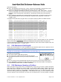
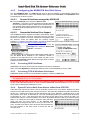
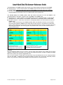
If we delete the first file with a long file name on an Atari the directory table is modified as follow:
Offset
0002A000
0002A010
0002A020
0002A030
0002A040
0002A050
0002A060
0002A070
0002A080
0002A090
0002A0A0
0002A0B0
0002A0C0
0002A0D0
0002A0E0
0002A0F0
0002A100
0002A110
0002A120
0002A130
0002A140
0
53
8D
44
FF
03
47
02
4F
01
53
E5
8D
53
8D
42
FF
01
4F
4C
8D
00
1
48
3B
54
FF
52
00
41
00
54
00
48
3B
48
3B
41
FF
4C
00
4F
3B
00
2
4F
8D
00
FF
00
20
00
46
00
20
49
8D
4F
8D
00
FF
00
4C
4E
8D
00
3
52
3B
58
FF
59
00
4D
00
48
00
53
3B
52
3B
4D
FF
4F
00
47
3B
00
4
54
00
00
FF
00
4E
00
20
00
41
49
00
54
00
00
FF
00
44
46
00
00
5
20
00
54
FF
20
00
50
00
49
00
53
00
46
00
45
FF
4E
00
4F
00
00
6
20
A0
00
FF
00
41
00
41
00
4E
7E
A0
4C
A4
00
FF
00
45
7E
A8
00
7
20
8C
00
FF
4C
00
4C
00
53
00
31
8C
44
81
00
FF
47
00
31
81
00
8
54
8C
00
FF
00
4D
00
20
00
20
54
8C
20
8D
00
FF
00
52
20
8D
00
9
58
3B
FF
FF
4F
00
45
00
20
00
58
3B
20
3B
FF
FF
20
00
20
3B
00
A
54
02
FF
00
00
00
00
00
00
00
54
03
20
04
FF
00
00
00
20
05
00
B
20
00
0F
00
0F
00
0F
00
0F
00
20
00
10
00
0F
00
0F
00
10
00
00
C
00
0E
00
FF
00
45
00
56
00
45
00
0E
00
00
00
FF
00
20
00
00
00
D
0F
00
43
FF
43
00
43
00
43
00
92
00
72
00
68
FF
68
00
4E
00
00
E
9B
00
FF
FF
4E
2E
20
45
49
58
9D
00
A3
00
FF
FF
46
4E
A7
00
00
F
81
00
FF
FF
00
00
00
00
00
00
81
00
81
00
FF
FF
00
00
81
00
00
SHORT
TXT ..›•
•;•;.. ŒŒ;......
DT.X.T...ÿÿ..Cÿÿ
ÿÿÿÿÿÿÿÿÿÿ..ÿÿÿÿ
.R.Y. .L.O...CN.
G. .N.A.M...E...
.A.M.P.L.E...C .
O.F. .A. ...V.E.
.T.H.I.S. ...CI.
S. .A.N. ...E.X.
åHISIS~1TXT .’••
•;•;.. ŒŒ;......
SHORTFLD
..r£•
•;•;..¤••;......
BA.M.E...ÿÿ..hÿÿ
ÿÿÿÿÿÿÿÿÿÿ..ÿÿÿÿ
.L.O.N.G. ...hF.
O.L.D.E.R... .N.
LONGFO~1
..N§•
•;•;..¨••;......
................
We can see that now only the 8.3 entry at 0x2A0A0 is mark as erased (0xE5) but the associated
dummy LFN entries (grayed above) starting at 0x2A020 are left untouched which is pretty bad!
It is also interesting to note that even with BigDOS loaded the same, bad, behavior happen that is the
dummy LFB are not erased. ??? TODO check
3.2
TOS Maximum Path Depth
All the TOS versions prior to 2.x have a limitation for the maximum depth level of a path that can be
manipulated from the desktop. This maximum level is equal to 8.
By depth level I mean the number of path elements located between separators. For example
C:\Folder1 is one level deep; C:\FOLDER1\Folder2 is two level deep, etc…
Therefore from the desktop:
You cannot create a folder above 8 levels
You cannot copy a folder tree that has more than 8 levels
Universal Item selector won’t let you create a new folder on level
above 8.
However:
You can access from the desktop folder and files at any level (of course if they already exist).
From a program it is possible to create and access correctly more than 8 levels. This seems to
indicate that the problem does not reside in GEMDOS.
3.3
TOS Maximum Number of Folders
Atari's TOS has a bug; known as the "40-folders limit". Every time you access a folder information
about that folder is loaded into a memory table. As the memory table’s size is small it runs out of
space after you've touched around 40 folders. After that the disk operating system might write
incorrectly sectors resulting in lost clusters, cross-linked clusters, etc. To make this worse, folder
"slots" are used up just by doing “Show Info…” and therefore it is easy to run out of folder slots. One
common symptom of this is that when you open up a new directory box, and you get data or program
© Jean Louis-Guérin – V1.2a – September 2014
Page 14 / 69
files that belong somewhere else. Or you get “0 files in 0 items” box, making you think everything has
just been erased.
If this happens, reboot immediately; if you write anything to that hard disk, you're going to
damage the directory structure. Your data is probably still out there and still okay. Upon restarting,
go immediately to the offending directory, and try again; if it works this time you were lucky.
Atari has released an "official" 40-folder bug fixer program, called FOLDRXXX. What you do is put this
program in your AUTO folder with the XXX replaced by how many folder slots you'd like to reserve.
For instance, for 100 folders, name the program "FOLDR100.PRG" in the AUTO folder. At boot-up,
FOLDRXXX adds more memory to the folder memory space.
Starting with TOS 1.04 or above Atari has rewritten the GEMDOS and this problem is partially solved:
Memory is used only by open folders and not anymore by touched folders (prior to 1.04 the memory
was not recycled). This means that you are
running out of folder memory less rapidly. But
you can still run out of folders (see the
Discussion of OS Pool for more details).
It seems that TOS 2.X and above definitely fix
the problem (but I have not tested it).
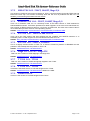
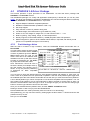
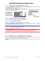
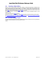
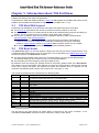
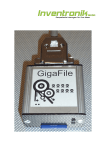
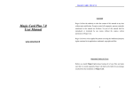
The TOS system does not handle gracefully
running out of folders. The picture shows the
messages displayed by the system when a
program tries to access too many folders.
Several programs/utilities fix the “40-folder bug”. We have already
mentioned the FOLDRXXX.PRG released by Atari but many other
utilities also fix this problem. In particular many Hard Disk driver
provide an option to increase the number of buffers allocated for
folder. The picture on the right shows the option (in general options)
to allocate additional folders with the HDDRIVER hard disk driver.
3.4
TOS Maximum number of files
Depending on the TOS version the maximum number of files and folders for FAT16 (AHDI) partitions
is limited to a maximum of about 32000.
3.5
TOS Maximum number of partitions
It is difficult to find information about this limit in the literature. However it seems that the maximum
number of Hard Disk partitions that can be “installed” (or I should say “mounted”) on a system is 14.
The standard Atari File Selector only goes from letter A to P (2 letters for the floppy disks, and 14
letters for the hard disks). This limitation is clearly indicated in the Atari AHDI 3.00 Release notes (in
the PUN section page 15) where the MAXUNITS parameter is defined as 16 (including floppy drive A:
and B:). It does not seem that new releases of TOS have changed this limit.
Note that this maximum limit is to share for all the connected drive. This also implies also that the
maximum number of partitions for one drive is 14.
With BigDOS the limit is uplifted to 29 (C – Z except U) + 1-6.
With Mint the limit is 23 partitions (C – Z except U).
3.6
Discussion of OS Pool (from Rainbow TOS release notes)
There are internal limits in GEMDOS which programmers and users must understand. In a broad
sense, you should know that these limits have to do with the maximum depth of your hierarchical file
structure (subdirectories), and the number of open files you can have at once. In most cases, users
will never come up against any of these limits.
The limits come into play when you have lots of files open at the same time, and they are deep in
different subdirectory trees. Also, programs which call the operating system function Malloc (memory
allocator) influence these limits: lots of Malloc calls means less space is available for keeping track of
open files and the subdirectories leading up to them.
© Jean Louis-Guérin – V1.2a – September 2014
Page 15 / 69
Technically, the limits are as follows: there are 80 blocks in the system's “OS pool” two blocks are
used per active folder. An “active” folder is one which is the root directory of the device it's on, or which
has open files, or which is somebody's current directory, or which has an “active” child (subdirectory).
Yes, this is a recursive definition. Remember that each process has a current directory on every
logical device, but also remember that one folder only takes up two blocks, no matter how many
reasons its “active.”
In addition, one block is used per open file, and 1/4 block is used per memory chunk (allocated or free)
in the system memory.
When files are closed, memory chunks are freed, and when processes terminate, blocks are treed
back into the OS pool.
The TOS 1.4 and above has the following improvement over previous ROMs: the old definition of
“active” was “seen” getting a list of the files in a directory caused all the folders there to take up blocks
in the pool. In addition, blocks were never freed in the pool. Also, once parts of the pool had been
used for managing Malloc memory chunks, they were unavailable for managing folders, and vice
versa. All these restrictions are lifted.
It is still possible to run out of OS pool, of course. The program FOLDR100.PRG was released by Atari
and is part of the HDX (hard disk utilities) distribution. It adds memory to the OS pool, and it still works,
adding memory to the new kind of pool, too. Placing this program in your AUTO folder causes 200
more blocks to be added to the OS pool, which is room for 100 more folders (remember, only active
folders take up room) or 800 more memory chunks, or any combination.
The name FOLDR100.PRG can be changed: the three digits in the name are interpreted as the
number of “folders” you want to add at two blocks each. So FOLDRO5O.PRG would add only 100
blocks, while FOLDR200.PRG would add 400. No matter where the program is started from, it looks
for itself in the \AUTO\ folder of the boot device to determine how many blocks to add.
It is to be stressed that this program usually will not be necessary. Only if you have an inordinate
number and depth of folders, open files, etc. will you run out of pool, because it is so much more
efficiently managed than before.
In the unlikely event that you do run out of pool, the following message will appear on your screen:
*** OUT OF INTERNAL MEMORY:
*** USE FOLDR100.PRG TO GET MORE
*** SYSTEM HALTED ***
This message appears in English regardless of the country you are in.
It is regrettable but true that there is nothing you can do at this point but hit the reset button or use the
keyboard reset combination (CTRL-ALT-DELETE). Remember what you were doing when this
happened: were you trying to create a directory that was 50 levels deep in the hierarchy? Were you
opening the tenth different file in the tenth different subdirectory? If you really want to be able to do
whatever you were stopped from doing, use FOLDR100.PRG (or increase the “100” if you're already
using it).
Note: the system call Malloc will never cause a panic: it will just return 0, meaning it couldn't satisfy the
request. When this happens, however, your program has stretched the limits of the system, because
that means there is not even 1/4 of one block available for the memory manager. At this point a welldesigned program will detect the condition (out of memory) and terminate, freeing up enough blocks to
be useful.
3.7
TOS Version Specific Limitations
The information presented here comes from the Towns' Little Guide to Revisions - Version 1.0 written
by John Townsend from Atari Corporation
3.7.1
ROM TOS 1.0 - 520ST and 1040ST
The original TOS shipped with 520ST and 1040ST computers. This version is relatively slow and has
a lot of problems with disk I/O. You should try to avoid using hard disks with this version.
Utilities: FOLDRXXX.PRG
© Jean Louis-Guérin – V1.2a – September 2014
Page 16 / 69
3.7.2
MEGA TOS 1.02 - 520ST, 1040ST, Mega 2/4
This version of TOS fixes some minor problems in TOS 1.0 and has support for the BLiTTER chip and
Real-Time Clock chip. This version is relatively slow and has a lot of problems with disk I/O. You
should try to avoid using hard disks with this version.
Utilities: FOLDRXXX.PRG
3.7.3
Rainbow TOS 1.04 – 520ST, 1040ST, Mega 2/4
TOS 1.04 or Rainbow TOS, as it is commonly known is the latest version of TOS released for
520/1040/MEGA owners. It has been provided as a dealer upgrade. It has much more robust Disk I/O,
Auto running of GEM programs at boot up, a fix for the 40 folder limit, and much more. Most of all is it
much faster than previous versions of the Operating System.
Utilities: TOS14FIX.PRG, POOLFIX3.PRG, CACHEXXX.PRG, FOLDRXXX.PRG
3.7.4
STE TOS 1.06 - 1040STE and 520STE
TOS 1.06 is the TOS version that was shipped with the 1040STE and 520STE machines. It is
essentially TOS 1.04 with support for the new hardware that the STe has.
Utilities: STE_FIX.PRG, POOLFIX3.PRG, CACHEXXX.PRG, FOLDRXXX.PRG
3.7.5
STE TOS 1.62 - 520STE, 1040STE
This is a slightly revised revision of TOS 1.6. It fixes the POOLFIX problem in GEMDOS and the
problem in the Desktop that was present in TOS 1.06.
Utilities: CACHEXXX.PRG, FOLDRXXX.PRG
3.7.6
Mega STE TOS 2.05 - Mega STE
TOS 2.05 is the version of TOS shipping in the Mega STe.
Utilities: CACHEXXX.PRG, FOLDRXXX.PRG
3.7.7
TT TOS 3.01 - TT030
TOS 3.01 is the version of TOS that originally shipped in the TT030.
Utilities: CACHEXXX.PRG, FOLDRXXX.PRG
3.7.8
TT TOS 3.05 - TT030
TOS 3.05 is the latest version of TOS that shipped in the TT030.
Utilities: CACHEXXX.PRG, FOLDRXXX.PRG, SERPTCH1.PRG
3.7.9
Falcon TOS 4.X
TOS 4.x is the version of TOS that shipped in the Falcon
© Jean Louis-Guérin – V1.2a – September 2014
Page 17 / 69
Chapter 4. Atari Hard Disk Drivers Packages
This chapter provides a quick guide of several Atari hard disk drivers usage. It is primarily written for
users of CosmosEX, UltraSatan, and Satan devices. If you want to use these drivers with other
hardware or need more advance options you should refer to the original documentation.
For each driver we provide detailed procedures to:
Partition and initialize a drive,
Install the hard disk driver, and
Eventually configure the installed hard disk driver.
4.1
Hardware Configurations Tested
Due to the fact that I have access to a limited set of hardware, and a limited time, I have performed the
tests with the following Atari Computers and Devices:
Atari 1040 ST with US TOS 1.04 and 4 MB of RAM
Atari 520 STE with French TOS 1.62 and 4 MB of RAM
Satan Device, UltraSatan Device, and CosmosEx Device
4.2
Information on Removable Drive
In order to support removable media a hard disk driver needs specific features described by AHDI.
4.2.1
Disk Change Support
When the removable media is changed, the driver must recognize this the next time the drive is
accessed and the drive must be logged again. If the new media has more partitions than the previous
one, these should be added after the currently logged partitions.
4.2.2
Specification of the Maximum Logical Sector Size
In most of the drivers you have to specify a maximum logical sector size. At boot time, the driver will
use this number to allocate internal read and write buffers. This is especially important when you need
to switch media on a removable drive (e.g. on an UltraSatan), and the media are partitioned differently.
For example, suppose that you boot up the system and the size of the biggest logical sector on all the
logical drives plugged in is 2048 bytes. Later, you need something from a removable media that has
partitions whose logical sectors are 4096 bytes big (call it removable media A). If the maximum logical
sector size has been set to 2048, you cannot access the partitions on removable media A whose
logical sectors are 4096 bytes big, because the driver buffers are not big enough for its logical sectors.
4.2.3
Number of Partitions on a Card
With drivers that support removable media, usually you can specify the number of drive letters to be
reserved for each unit. This number will only be used if the unit supports a removable media.
This is useful when you need to switch media on a removable drive (e.g. on an UltraSatan), and the
medias are partitioned differently. At boot time, the driver will use this number, or the number of logical
drives on a removable drive, whichever is bigger, and assign that number of drive letters to that
particular unit. For example, suppose that you boot with a media that has two partitions on it (call it
media A) in the drive. Later, you need something from another media that has four partitions on it (call
it media B). If the reserved number of drive letters for this removable drive has not been set to be
greater than two, you cannot access the last two partitions on media B, because only two drive letters
were reserved for this removable drive.
4.3
4.3.1
Things to check before you start
Satan device
Satan device has limited ICD command support and no HxSD card support. Therefore most driver will
only support 1GB media except PPDRIVER that correctly detects cards up to 2GB.
4.3.2
UltraSatan device
Due to incompatibilities with the SCSI standard in old UltraSatan firmware versions HDDRIVER and
PPDRIVER only supports UltraSatan firmware versions 1.13 or newer. It is therefore recommended
that UltraSatan users flash their device to the latest firmware.
© Jean Louis-Guérin – V1.2a – September 2014
Page 18 / 69
4.4
HDDRIVER 9.02 Driver Package
This section presents a quick procedure to follow to use HDDRIVER 9.02 hard disk driver package on
CosmosEx or UltraSatan device. The HDDRIVER package is a commercial application that you can
buy from Uwe Seimet HERE. For detail information please refer to the provided documentation.
Many improvements and bug fixes has been included in V9.x. For UltraSatan and CosmosEx users
on ST machine the most important feature added (actually added on version 8.40+) is the support for
multiple TOS & Windows partition on compatible media. The configuration of the driver is also much
easier as it automatically detect if the drive support ICD extensions.
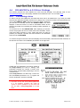
4.4.1
Partitioning a drive
In order to use the HDDRUTIL.APP utilities the HDDRIVER hard disk driver has to be loaded.
Normally this is done automatically if you boot from the HDDRIVER diskette as the HDDRIVER.PGR
program is located in the Auto folder. The driver displays a welcome screen and displays information
about all the connected devices and eventually already existing partitions.
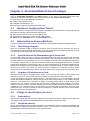
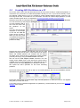
HDDRUTIL.APP program displays two windows
with all known devices and partitions. The device
or partition to operate on can be selected from
these lists. The operations available for the
selected item are enabled in the main menu and
are also offered by a context menu, which is
displayed when selecting an item with the right
mouse button.
As we are starting with a DOS formatted SD card
on a CosmosEx device only one partition is shown
here.
Select the device that contains the media you
want to partition from the Devices Window and
from the Medium menu select the Partition
command.
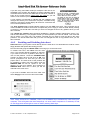
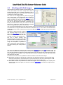
The Partition form will popup. If the hard disk has already been partitioned you will
see the current values otherwise you will see some default values.
First you need to define the type of partition you want to create by clicking on the
Compatibility button in the partition window. This open the Compatibility Option
window. You have three choices: TOS only, Windows only, and TOS & Windows.
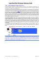
4.4.1.1
Creating a Windows only partition
If you want to create DOS/Window only partitions I recommend
that you use specific tools directly on the PC.
4.4.1.2
Creating a TOS only partition
Check the TOS checkbox and uncheck the Windows checkbox.
Select the TOS level of compatibility you want with the radio
button and click OK.
4.4.1.3
Creating a TOS & Windows Partition
The “TOS & Windows Combined” checkbox from previous version of HDDRIVER has been removed.
In order to create TOS & Windows compatible media simply check both the TOS and Windows
checkboxes. Select the TOS level of compatibility you want with one of the radio buttons. You
probably want to leave the two checkboxes in the Windows section uncheck, unless you know what
you are doing (refer to your documentation). Click OK this return you to the partition window.
© Jean Louis-Guérin – V1.2a – September 2014
Page 19 / 69
4.4.1.4
Actual Partitioning
Once you have defined the compatibility options
for the partitions you are returned to the main
partition window. In the MB field you have to
specify the size of every partition you want to
create. Usually you do not want to enter any value
in the TYPE fields unless you know exactly what
you are doing (please refer to the HDDRIVER
documentation).
Enter the size for all
the partitions you want to create. Remember that for example with TOS
1.04 the partitions must be less than 512MB. Verify also that the total
size of all partitions you have defined is less than the available capacity.
Click OK to start the partitioning. At the end a window indicates that the
partitioning has been finished. Note that the initialization of the partitions
is done as part of the partitioning.
The Drives Window now displays all the created partitions. The program proposes to restart the
system and it is better to select Now.
4.4.2
Enabling and
Auto boot
Disabling
Execute the HDDRUTIL.APP program. Select the
Partition you want to use to boot from. The primary
partitions suitable for an installation are marked
with a leading ‘.’.
From the File menu select
the Install HDDRIVER…
command. A confirmation
will be asked and a popup window will indicate that the driver has been
installed.
To disable the Auto boot: From the File menu select the Remove
HDDRIVER…
command
and
follow
the
instructions.
© Jean Louis-Guérin – V1.2a – September 2014
Page 20 / 69
4.4.3
Configuring the HDDRIVER Hard Disk Driver
Run the HDDRUTIL.APP. The hddriver.sys driver of the boot partition is automatically selected for
you. With HDDRIVER 9.x most of the default values required for CosmosEx, and UltraSatan users
are already set to what you want.
4.4.3.1
Devices & Partitions managed by HDDRIVER
From the Settings menu select the Devices and
Partitions… command. You are presented a window with the
Devices and Partitions options. Make sure that all devices 0.x
are checked (other might be checked too). This will ensure
that all ACSI devices (with IDs from 0 to 7) are handled by
HDDRIVER.
4.4.3.2
Removable Medium Drive Support
The HDDRIVER driver supports removable media drives. When
the media is changed, the driver recognizes this the next time
the drive is accessed. If the new card has more partitions than
the previous, these are added after the currently logged
partitions. To support removable medium you need to set the minimum number of partitions and sector
size (see Important Parameters for Removable Drive).
Run the HDDRUTIL.APP. From the
Settings menu select the Removable
Media… command.
You are presented a window with the Removable media options.
Set the Drive ID to reserve to the maximum number of
partitions to be expected on any of the media you plan to use.
Set also the maximum sector size to the larger value for all the
partitions on all the media.
4.4.4
Accessing DOS Partitions
HDDRIVER can directly access FAT16A partitions of less than 32 Mbytes.
When used with BigDOS the HDDRIVER allows access to FAT16B partitions of up to 2GB.
4.4.5
Accessing TOS & Windows Partitions
HDDRIVER allows access to TOS & Windows partitions created by HDDRIVER.
Important Warning: never try to access TOS&DOS partitions created by PPDRIVER hard disk driver
with HDDRIVER as they are not compatible.
Remember that with TOS 1.04 the size of the partitions is limited to 512MB. It is possible to create
several TOS & Windows partitions on a SD card with HDDRIVER. All these partitions can be accessed
by the TOS on Atari and by Windows on a PC.
4.4.6
Special Care to boot from device other than ACSI ID0
If the device you want to boot from is not on ACSI ID0 you have to be very careful. Suppose you want
to boot from an USB memory stick found on ACSI ID1. Just follow the standard procedure described in
section 4.4.1. Reboot the system load the HDD driver and run the HDDUTIL. Install the driver on the
first partition of the drive as described in 4.4.2 and immediately before you reboot enable all devices
as described in 4.4.3.1. This will ensure that your device at ID1 will be seen correctly by HDD. You
probably also want to mount this partition as C drive. By default ID0 device will get a reserved mount
letter C. To change this you need to modify the order the HDD
driver will scan the boot devices. In the Devices and
Partitions form drag and drop the 0.1 entry on top of the 0.0
entry. This will force HDD to scan ID1 before ID0 and therefore
the boot partition of the drive found at ACSI ID1 will be
mounted as C.
© Jean Louis-Guérin – V1.2a – September 2014
Page 21 / 69
4.5
PPDRIVER 1.0 Driver Package
This section presents a quick procedure to use PPDRIVER 1.0 hard disk driver package with
UltraSatan or CosmosEx devices.
The PPDRIVER package is a cheap 10€ application developed by P.Putnik that you can buy from
HERE. This driver has limitations compared to HDDRIVER as it has been designed almost exclusively
for Satan, UltraSatan and CosmosEX devices. It provides:
+
+
+
+
+
+
+
+
+
4.5.1
Support Multiple TOS/DOS compatible partitions
Bootable TOS&DOS Partition (512MB for TOS 1.04)
Hot-swap support
Easy selection of active C partition during boot
Low RAM usage, Good Performance (pure ASM only code)
Works on ST, STE, Mega ST, Mega STE, TT with minimum TOS v. : 1.02
Ideal for gaming - easy setting, usage, no Timer dependence
Directly support FAT16A DOS Partitions (< 32MB) and plain AHDI TOS partitions
Maximal support for gamers: driver loadable without XHDI, in top RAM, with HOLE (for old
games, not compatible with higher TOS versions)
Partitioning a drive
Start the Atari in medium or high resolution, insert the PPDRIVER diskette and double click on
PP12U.PRG.
You first need to select the ACSI Id that
contains the CosmosEx device. ACSI 0
is shown by default. Ignore the Master,
Slave buttons that are used for IDE
drives. If the drive is at a different ACSI
Id address use the up and down arrows
to select an Id between 0-7. Tw. IDE is
for people with twisted IDE cable.
Once selected the correct ID click on
the drive’s button (for example ACSI 0),
the disk Vendor and capacity will be
shown. If any the previous partitioning
is displayed for DOS compatible
partitions.
You now have to enter the desired sizes for each partitions starting with partition C. Each time you
enter a value for a partition the free space field is updated. If the sum of all partitions gets bigger than
the available space the free indicator shows NEG and in that case you must decrease some partitions.
C16 is default partition type, which correspond to TOS & DOS compatible FAT16A partition. You can
also create FAT32 partitions, but you will need Magic or Mint to be able to access them on Atari. It is
therefore recommended to leave the type to C16. To change the type you can click the Change type
button or click the type indicator close to the drive letter.
Once you are satisfied with the partition sizes, click the PARTIT. and INIT all button.
Nothing is written on disk until you press the Go on! Button.
Note that Init button here means practically same as “format” in PC terminology.
After partitioning, you may check the result by clicking again the Drive button - it should show the new
partitions as they are set.
Now you can Click EXIT
© Jean Louis-Guérin – V1.2a – September 2014
Page 22 / 69
4.5.2
Installing the Auto boot Driver
To install the auto boot driver you need to execute the USAB10.TOS program.
The driver installer will show all attached ACSI devices with target # and capacity detected. You first
have to select the device you want by typing the target value and press I key to confirm installation
(any other key will result in exit without install).
The program will install the driver in few seconds and will confirmed the installation. The drive is now
ready. You can restart computer, and it will auto boot, and mount the partitions defined.
Note that contrary to other HD drivers, PPDRIVER does not install the boot code in a specific partition
but in the free space (30KB) just after the MBR. This allow to select the C partition you want to use
from the list of all the available partitions on the media at boot time.
Option for uninstalling driver does not exist, because it makes no sense. Driver will be simply
deactivated if you install another driver on the media.
PPDRIVER supports TOS/DOS partitions created with the PP12U.PRG utility. It should also work with
TOS&DOS partitions created with HDDRIVER.
Note that PPDRIVER does not have any configurable option. It does not support XHDI and does not
include FOLDER100. This was done on purpose not to waste any space for gamers.
4.5.3
Removable Medium Drive Support
The PPDRIVER driver provides support for removable medium drives. The driver detects media
change and reinstalls all partitions at the next disk access after the media has changed.
The user needs to refresh the Desktop with Escape key. If you close a window, and reopen it, the
window will still show the old content until you press Escape key. This is strange, and indicates that
obviously TOS do not use media change detection for hard disks in the Desktop.
4.5.4
Accessing DOS Partitions
PPDRIVER can directly access FAT16A partitions of less than 32 Mbytes.
PPDRIVER driver is not designed to work with BigDOS as it does not provide XHDI support. If want to
use partitions over 512MB with BigDOS, you can download an older (and free) driver from P.Putnik
site.
4.5.5
Accessing TOS&DOS Partitions
Note that latest version of PPDRIVER allow access to TOS&DOS (TOS & Windows) partitions created
by PPDRIVER and by HDDRIVER.
Remember that with plain TOS the size of the partitions is limited to 512MB. Although it is possible to
create several TOS & Windows partitions on a SD card with PPDRIVER, Windows normally only
access one partition on a removable media. However by using the procedure describe in Accessing
Multiple Partitions from SD Cards it is possible to access all the partitions created by PPDRIVER
directly in Windows.
For example I have created 4 partitions using a 2GB SD card plugged on a CosmosEx device. As all
the resulting partitions are below 512MB they can be read correctly directly from ST. Using the Hitachi
Microfilter driver it is also possible to directly access these 4 partitions directly on Windows.
4.5.6
Driver usage
Most interesting feature is selecting active C partition during boot - just follow messages on screen.
Although driver auto boots only from DOS/TOS compatible partitions it handles AHDI (TOS) type
partitioned disks/medias too. Therefore if drive with TOS partitions is attached (can’t be a boot device),
the partitions will be mounted.
Of course, you need to take care about the TOS partitions limit with a maximum of 14 (C-P).
There is another limit in this driver: a maximum of 3 ACSI targets is supported.
© Jean Louis-Guérin – V1.2a – September 2014
Page 23 / 69
4.6
ICD AdSCSI Pro 6.5.5 Driver Package
This section presents the ICD AdSCSI Pro 6.5.5 hard disk package. This package used to be a
commercial package but is now widely available as an abandon-ware. You can find it here.
4.6.1
Partitioning a drive
In order to use the ICD utilities the ICD hard disk driver has to be loaded first. If you boot your Atari
with the ICD distribution diskette inserted in the floppy drive, the driver should load automatically as a
copy of the ICDBOOT.PRG is placed in the AUTO folder. Otherwise
you will have to manually execute the ICDBOOT.PRG. The driver
displays a welcome screen as well as information about all the
devices connected and eventually the already existing partitions on
the drive.
You should now run the ICDFMT.PRG. After displaying a welcome
screen the program will scan for hard drives and controllers. All the
units found will be listed in a form. Select the Drive you want to
partition (for example a specific SD Card inserted in an UltraSatan
drive) and click CONTINUE.
You will be brought to the main menu that displays some information, about the hard disk selected, on
the left side and some user modifiable parameters on the right side.
Usually the only parameter you need to modify is
the Verify Passes (it is set to 1 initially). This
parameter indicates the number of times each
sector will be checked after partitioning to see if it
is a bad sector.
Click Verify Passes: This will bring a new form.
Set the Passes parameter to 0, to bypass the
sectors verification, and then click OK.
If you do not set the Verify Passes parameter
to 0 the partition operation will check all
sectors in all the partitions on the drive and
this can take a very long time on a large
drive.
© Jean Louis-Guérin – V1.2a – September 2014
Page 24 / 69
Now you should click PARTITION. You are now presented the partition Main form. If the drive had
already been partitioned you will see the values from the previous partitioning otherwise you will see
some computed default values.
The window has many fields that you can modify but the most useful ones are:
The Size that specifies the size for each partition. Here you can enter the desired sizes for all the
partitions that you want to create. At any time you can click RECALCULATE or hit return key to
update the excess field (display the remaining space).
Name is the name of the partitions. The Show Info... from the Atari desktop will display this value.
The On column contains check marks for enabled partitions. Normally you always want to set a
checkmark for all the partitions otherwise they will not be accessible (hidden).
Note that the size displayed and entered values are in MEGS (10002) and not in megabytes (10242).
Click PARTITION ENTIRE HARD DISK: This writes the partition information based on values you
have entered into the MBR of the hard drive. It will also write the boot sector, FAT, and directory
information to each partition.
WARNING: Before partitioning make sure you that you have a check mark in the On column for
all the partitions. Otherwise the program will warn you. You can click CANCEL and set On flags.
The program asks you to confirm and displays progress information …
At the end it should indicates that partitioning has terminated successfully. You are then offered to
print the partitions information and you probably want to click CANCEL.
© Jean Louis-Guérin – V1.2a – September 2014
Page 25 / 69
If you are using removable media (for example a SD card on an
UltraSatan) the program also displays a window indicating that a
removable drive has been formatted and the maximum number of
bytes for the logical sectors. Write down this value as you will
need it to set the driver parameters and click OK.
A new window is presented to indicate that the partitions have
changed and offers you to reboot the computer, click OK. During
reboot the ICD driver should display all the drives connected and
a list of all the partitions found.
The write partition only command allows rewriting only the MBR of the drive. This command can be
used if the MBR of the drive have been corrupted and you are trying to save the data already existing
on the drive. You should make sure that you have not changed the size of any partition when you use
this command.
The rebuild one partition only command reinitializes a specific partition (rebuild boot sector, FAT,
and the Root Directory). The program will ask you which partition you want to rebuild. This command
can be useful if you have only one partition corrupted and you want to keep the data in the other
partitions. You should make sure that you have not changed the size of any partition when you use
this command.
4.6.2
Enabling and Disabling Auto boot
Auto boot allows your system to boot directly from the hard drive. This eliminates the need for a boot
floppy diskette and speeds the booting process.
Run the ICD utility program HDUTIL.PRG. This brings you to the main menu.
To enable Auto boot, click Boot from the main
menu. The program default to partition C selected.
If you wish to boot from a partition other than C,
click on that partition. Locate the ICDBOOT.PRG
(usually on floppy drive A) and click on OK. You
will be prompted to be sure that you have the
proper disk in. The boot sector of the partition will
be modified to reflect Auto boot status, and the
ICDBOOT.PRG file will be copied to the root
directory of the boot partition and renamed to
ICDBOOT.SYS. When this is done you will be
returned to the main menu.
If you want to disable Auto boot from hard click
select Floppy as the boot drive and click on OK.
Note: If you wish to boot from floppy only on occasion it is not necessary to disable boot from hard
drive. Simply hold down the CONTROL, SHIFT, and ALTERNATE keys simultaneously while booting the
computer. This will bypass Auto boot temporarily. On some newer computers it is necessary to wait
for the floppy drive access light to come on before pressing these keys.
© Jean Louis-Guérin – V1.2a – September 2014
Page 26 / 69
4.6.3
Configuring the AdSCSI Hard Disk Driver
Run the ICD utility program HDUTIL.PRG. This brings you to the main menu.
Click Config: All parameters are grayed because you first have to select the driver you want to
configure. Select the driver from your boot partition (for example C:\ICDBOOT.SYS). You should see
all the current parameters of the driver
installed. You probably do not want to
change any of these parameters with
the following exceptions:
Max size for logical sector: If you
are using removable media (e.g. SD
cards on an UltraSatan) you must
adjust the size for logical sector with
the value that was reported at the
end of the partitioning operation.
This is done by pressing the
up/down arrow buttons at the
beginning of the line. See 4.2.2
Set Clock: you have to select NO for
the clock option unless you are
using AdSCSI Plus ICD board.
Click Save: The program displays a file
selector: select save to
C:\ICDBOOT.SYS. Now click the Exit
button to terminate the configuration.
The program returns to the main screen and you can now click on QUIT.
A new window will pop up to remind you that ICDBOOT.SYS has been modified and offer you to
reboot the computer: click OK.
Note: The maximum size for logical sector is an important parameter as it reserves buffers
required by the driver. If you are using several SD cards this parameter should set to the
maximum of the values reported during formatting of all the partitions on all the cards. See also
section 4.2.2
There are some other parameters that can be changed and that will affect the performance of the
driver but they are beyond the scope of this document and therefore not described. Please refer to the
ICD documentation for more information.
4.6.4
Removable Medium Drive Support
The ICDBOOT driver supports removable medium drives. When the card is changed, the driver
recognizes this the next time the drive is accessed, a “Disk Change” message is flashed in the upper
right-hand corner of the screen, and the drive is logged again. If the new card has more partitions than
the previous, these are added after the currently logged partitions. However it is not possible to
reserve a number of partitions attached to a drive.
4.6.5
Accessing DOS Partitions with ICD
The AdSCSI hard disk driver only supports DOS partitions of type FAT16A. Remember that these
partitions are limited to 32MB. AdSCSI Hard disk driver does not support XHDI 1.2 and
consequently the BigDOS program cannot be used with this driver. Note that this is strange as ICD
advertise XHDI 1.2 and BigDOS support here.
4.6.6
Accessing TOS&DOS Partitions
ICD AdSCSI does NOT support TOS&DOS partitions.
Important Warning: Never try to access TOS&DOS partition with the ICD AdSCSI hard disk
driver. You will get invalid data returned and you will probably corrupt the accessed partition.
© Jean Louis-Guérin – V1.2a – September 2014
Page 27 / 69
4.7
CBHD 5.0.2 Driver Package
This section presents procedures for partitioning and using a drive with the CBHD package.
This CBHD 502 package is widely available as a freeware.
Note: The original CBHD package is in German. However most of the program and utilities have been
translated to English. This is the version presented below.
4.7.1
Partitioning a drive
In order to use the CBHD utility the SCSIDRV.PRG program needs to be executed first. The driver
displays a welcome screen but more importantly it displays information about all the devices
connected.
Run the CBHDCONF.APP: From the Disk menu select the
Partition… command. Select the drive you want to partition. If the
drive was already partitioned you will be presented with the
existing partitions.
You can change the size of any partition by clicking on the arrow
icons. When you reach the maximum size available on the disk
you will not be able to increment the partitions. Specifying size for
large partition can be painful!
Once you have specified the sizes click OK. Confirm with OK that you
want to partition disk.
This will write the partitioning information on the drive, and it will also
initialize the content of all the partitions. Reboot the system.
4.7.2
Enabling Auto boot
Auto boot allows your system to boot directly from the hard drive. This eliminates the need for a boot
floppy diskette and speeds the booting process.
Enabling auto boot with CBHD is “a bit unusual”. Please carefully follow the following steps:
Run the SCSIDRV.PRG then Run CBHDCONF.APP.
From the Driver menu select the Install… entry. This will
write the boot loader to the selected partition, but it will not
copy the driver to the boot partition for you.
Run the CBHD.PRG. You should now be able to access the
“C” boot partition from the desktop. If there is no hard disk
icon on the desktop you need to install a hard disk icon.
Copy the CBHD.PRG file from your installation floppy to this
partition. Rename this file to CBHD.SYS using File Show Info… from the desktop menus.
You should now reboot the system. The CBHD hard disk driver should load automatically and display
all the drives and partitions.
© Jean Louis-Guérin – V1.2a – September 2014
Page 28 / 69
4.7.3
Configuring the CBHD Hard Disk Driver
Run the SCSIDRV.PRG then Run CBHDCONF.APP. Load the CBHD.SYS from your boot partition
using Driver menu Load… command.
You can now modify several parameters according to your host
adapter and drives. For UltraSatan Drive I only found one
parameter that need to be checked.
From the Driver menu
select SCSI Driver…
Verify that the Identify
ICD is check marked (it
should be by default).
4.7.4
Removable Medium Drive Support
Not sure if there is any support for removable media in CBHD?
4.7.5
Accessing DOS Partitions
CBHD502 can directly access FAT16A partitions of less than 32 Mbytes.
When used with BigDOS the CBHD502 allow access to FAT16B partitions of up to 2GB. For example
I have tested a 2GB DOS partitions without problem.
Of course it is not recommended to use such a large partition for performance reason.
4.7.6
Accessing TOS&DOS Partitions
CBHD502 does not support TOS&DOS partitions.
Important Warning: Never try to access TOS&DOS partition with the CBHD502 hard disk driver.
You will get invalid data returned and you will probably corrupt the accessed partition.
4.8
SCSITools 6.5.2, and AHDI Driver Packages
Originally I had planned to present these hard disk drivers. However after testing it I discovered that
they only support a maximum size of 32MB for bootable partitions.
Because of this limitation and the fact they are very old I decided not to describe the procedures in this
document.
© Jean Louis-Guérin – V1.2a – September 2014
Page 29 / 69
4.9
Which Hard Disk Driver Should I use
Here we will only consider PPD1x, HDD9xx, ICD655, and CBHD502 drivers used with CosmosEX,
UltraSatan, and Satan devices on Atari ST.
The CBHD502 driver is very old and do not support well the new devices designed by Jookie and
therefore it should be avoided.
If you want a free solution then you have no other choice than using ICD655. This driver is not
maintained anymore but work relatively well with CosmosEx and UltraSatan disk.
If you use your system mainly for gaming with CosmosEx, UltraSatan, or Satan devices then
PPDRIVER is an excellent choice. It is cheap and it is the only one to support correctly multiple
TOS&DOS partitions on Windows.
The most powerful hard disk driver is HDDDRIVER. It supports all sorts of ACSI and SCSI devices
and has many features not found on other driver.
4.9.1
Hard Disk Driver Summary Table
PPDRIVER
HDDRIVER
ICD655
CBHD502
Boot TOS partition8
512MB
512MB
512MB
512MB
Boot TOS&DOS
Many
Many
No
No
Multi Boot
At boot time
Yes
No
Yes
FAT16A (32MB)
Yes
Yes
Yes
Yes
FAT16B (2GB)9
No
BigDOS
No
BigDOS
Removable media
Yes
Yes
Limited
?
XHDI
No
Yes
No
Yes
Maintained
Yes
Yes
No
No
Price
10 €
45 €
Free
Free
Performance10
8
The size of the Boot partition actually depends on TOS version. The value presented here is for TOS
version bigger or equal to 1.04 and less than 4.x
9 BigDOS means support by adding BigDOS program in the AUTO folder
10 Values given here are only useful as relative performance measured with my HDTEST program
using the same SD card on an UltraSatan drive.
© Jean Louis-Guérin – V1.2a – September 2014
Page 30 / 69
Chapter 5. PC Utilities
This chapter describes few programs that can be useful in relation with Atari Hard disk. For example to
partition, display content, and work with images of hard disks to be used on an Atari System.
5.1
Accessing Multiple Partitions from SD Cards
To access the SD card you will need a SD card reader on your PC. This can be for example an USB
card adapter. On this kind of adapter Windows allows access to only one partition even if your card
has multiple DOS&TOS partitions. To be able to read multiple partitions on Windows system the trick
is to force Windows to think that the removable media is a fix disk. Interesting article on the subject
Filter Drivers – Removable Media as Fixed Disk in Window
5.1.1
32 bits Windows - Hitachi Microfilter
There several solutions to access multiple partitions from an SD Card plugged into a PC card reader.
Here I present the solution I am using with the Hitachi Microfilter driver. You can find it from many
places like here. The Hitachi Microfilter is a card reader driver that allows seeing the card reader as a
hard drive.
Setting up the driver is very easy. You first need to extract the two files cfadisk.inf and cfadisk.sys in
a directory. Then start the Device Manager by executing the devmgmt.msc command.
In the device manager locate the card reader in the disk drive list, right
click on it and select Update driver software...
Select Browse my Computer for driver software.
Select let me pick from a list of device driver on my computer.
Click have disk button and locate the directory where the two driver files
are located.
Select the cfadisk.inf file and in the Install from disk window click OK,
ignore the fact that the driver not digitally signed message and click Next.
The driver is now installed for your SD card reader and let you access
multiple partitions on any SD card plugged into it.
Note that the procedure described above is for Windows 32 bits version only. The driver has been
tested on Windows XP, Vista, and 7 (all 32-bits pro editions).
Warning: When using the Hitachi driver your SD cards are now seen as hard disks. The
consequence is that if you delete files on a partition, Windows will automatically create two
invisible folders (marked with system and hidden flags): The System Volume Information folder
and the $Recycle.bin folder. Information about deleted files will be placed into these two folders.
5.1.2
64 bits Windows – Diskmod from Karyonix
The Hitachi filter does not work in the Windows 64 environment. There are several solutions available
to access Multiple Partitions from SD Cards on Windows 64 system. The Diskmod device driver is not
signed and installing it on a 64 bit systems is somewhat dangerous. Therefore I have decided to only
provide reference links that offers information about installation of this driver.
Flip removable media bit on windows 7 x64 - make a removable drive fixed
Multiple partitions & UEFI bootable SD card (Windows 8.1) and HERE
Diskmod 0.0.2.2
5.1.3
64 bits Windows – Access through virtual 32 bits machine
If you want to access Multiple Partitions from your SD Cards on a 64 bits system you can use a much
safer solution based on running a 32 bits version of windows on a virtual machine. For example you
can run an image of Windows 7 x86 with VMWARE. In the VM tab under removable devices you
should see an entry for your card reader you just need to connect it to the VM and the default driver is
installed. After that you just need to follow the procedure describe above for the Hitachi Microfilter.
© Jean Louis-Guérin – V1.2a – September 2014
Page 31 / 69
5.2
Creating DOS Partitions on a PC
As we have seen most of the Atari Hard disk drivers do not provide a utility to create DOS partitions. It
is therefore very convenient to create DOS partitions directly on a PC. If you connect directly a drive
(for example a SCSI drive) to a PC it is possible to create multiple partitions directly. However if you
are using an SD card, connected to a PC card reader, and want to create multiple partitions you first
need to install a specific driver, as explained in Accessing Multiple Partitions from SD Cards.
Windows comes with a reasonable utility for partitioning drives called the Disk Management Console.
You can execute it by executing the diskmgmt.msc command.
You are presented with a
list of all the drives and
the partitions on the
drives.
Your SD card should be
displayed. In the example
on the left the 8GB SD
Card is shown as Disk 5.
When you buy it the card
is formatted by default as
a FAT32 (only format for
partitions ≥ 2GB).
Suppose we want to partition the 8GB SD Card into four 2GB
partitions. We plug the card into a card reader that can handle
SDHC and multiple partitions (for example with the Hitachi
microfilter driver. We first have to delete the existing partition
(normally FAT32) by using the delete volume command.
We now use the new simple volume command. The new
simple volume wizard pops up. We specify the volume size to
1900MB, and in the format windows we select FAT for the file
system and we can keep Default for the allocation unit size.
We repeat the same operation for the three remaining
partitions.
At the end of this process we end up with our four 2GB partitions and we can immediately transfer
information from the PC on them.
Remember that in order to access these large FAT16B partitions on Atari you need to use BigDOS
along with your hard disk driver.
If you want to use a professional application for partitioning I recommend that you use The Hard Disk
Manager from Paragon.
© Jean Louis-Guérin – V1.2a – September 2014
Page 32 / 69
5.3
Working with Disk Images
A disk image is a file that contains an exact binary copy
of the raw content of the disk. Images are useful to
backup/restore SD card, to transfer information, and to
run with Atari emulators. There many tools available for
creating and reading disk images.
One nice tool for imaging/restoring SD card plugged
into a card reader is the USB-Image tool (currently in
version 1.68) that you can get from HERE. The card
reader containing the SD card should be displayed on
the left side. Select the drive you want and from there
you can use the backup and restore commands. The
backup command allows saving the content of the SD
card into an image file. While the restore command
takes an image file and write it to the SD card.
I do not use this USB-image tool very often because it does not recognize an SD card plugged into a
card reader when using the Hitachi Microfilter driver described above. This is due to the fact that when
using this driver the card is not seen any more as an USB stick but as a hard drive that this utility does
not handle.
Therefore my prefered tool for creating
and restoring images to be used on
Atari is the Drive Image program from
Peter Putnik. It works well with SD
card with or without the Hitachi driver.
Not only it allows creating and
restoring images of a drive, but it also
permits to look and modify the content
of the all the partitions inside the
image. For example it is possible to
add or extract files inside a partition. It
also allows dealing with TOS partitions
directly.
Two very nice utilities to deal with disk content are the WinHex editor and HxD freeware editor. As
their name indicates there main purpose is to edit the binary content of a raw disk or disk image. But
they are also capable to create and restore disk images of an SD card. And of course they offer many
more capabilities, for example I have used WinHex to look at the detail content of SD cards and/or
disk images of SD cards.
And last but not least are the capabilities of Atari emulators to deal with disk images:
With Steem emulator it is possible to create and/or use Atari disk images by using the Pasti hard
disk low level emulation. Unfortunately the current Pasti limits the size of the disk images to 1GB.
You will also need a tool like WinHex to transfer the images to/from SD Cards.
With Hatari emulator it is possible to use Atari disk images. I have tested quickly this capability that
seems to work well. And again you will need a tool like Drive Image to transfer the images to/from
an SD Cards.
© Jean Louis-Guérin – V1.2a – September 2014
Page 33 / 69
5.4
Partition Table Editor
Ptedit is a Free Portable Partition Table Editor created by Powerquest (Symantec). Ptedit32 can be
used to quickly and easily edit Partition Tables. For example it could be used to mark a partition active
"toggle the bootable flag" from within Windows. This is done by changing the boot indicator from 00 to
80. This tool can be stored and run from a USB device. You can download the Portable Partition Table
Editor HERE. Some technical details HERE or HERE (in French).
Note that on Windows 7 and Windows 8 you need to run the “resolve compatibility problem” for the
program to work.
Another alternative is the Bootice program.
Related to this there is nice small utility called ptcalc that allows conversion between LBA and CHS.
See Tools and References for the MBR and OS Boot Records and Free Tools to Backup and Restore
the Master Boot Record (MBR)
5.5
PC File Transfer Tools
In order to use files and directories without problems on an Atari you should not use Long File Names.
A tool like Total Commander can be very useful to do that.
TODO
© Jean Louis-Guérin – V1.2a – September 2014
Page 34 / 69
Chapter 6. Atari Utilities
6.1
BigDOS
BigDOS freeware Copyright© 1995 by Rainer Seitel
BigDOS is an ISO 9293 file system that replaces the GEMDOS of TOS.
6.1.1
Features
GEMDOS / ISO 9293:1987 / MS-DOS file system
32 Drives: A..Z 1..6 or A..Z [\]^_`
Up to 65518 cluster.
1 to 64 sectors per cluster.
More than 65535 sectors and therefore every MS-DOS partition possible. That means also more
than 32 MB.
1 or 2 FAT.
The legal characters are - configurable for each drive - restricted for GEMDOS, d-characters as in
ISO 9293 resp. ISO 9660 or MS-DOS. You know in advance, that a MS-DOS computer or
restrictive CD writing software can read all files. With setter.ttp from the HSModem archive, or the
GEM version of Setter, from Markus Kohm, this can be permanently set in BigDOS.
The disk label will also be written to an MS-DOS boot sector.
Works with or without MiNT.
BigDOS tries to lock removable cartridges using XHDI, if there were open files on it.
For TOS 1.04 and 1.06 no POOLFIX3.PRG, PFIX_CB.PRG or POOLFX92.PRG is needed.
For TOS 4 no F030HFIX.PRG is needed.
94 standards handles for open files, instead of 75.
Cookies ¯DATE® and ¯TIME® as in DTCOOKIE and LED-Panel.
Shows names of the loaded accessories.
6.1.2
Installing BigDOS
BigDOS.PRG (for the Falcon at present BigDOS-F.PRG) should be the first program in your AUTO
folder after the boot selector. In any case before every program in the GEMDOS trap which not use
XBRA. BigDOS.PRG installs itself at the end of the XBRA chain. You can use the Autosort program to
reorder the programs in your AUTO folder.
For MS-DOS partitions bigger than 32 MB, you also need a hard disk driver which can handle big MSDOS partitions (type 6) and allows access to more than 65535 sectors via Rwabs(). This should be a
driver with XHDI 1.20, because BigDOS tries to change the DOS limits via XHDOSLimits(). This
function could be checked with XHDItest.ttp.
6.1.3
BigDOS Sundries
DOSMODE.TOS shows and alters the legal characters for filenames on each drive:
GEMDOS: A..Z0..9!#$%&'()-@^_`{}~"+,;<=>[]| and capital umlauts
ISO: A..Z0..9_
MS-DOS: A..Z0..9!#$%&'()-@^_`{}~ and capital umlauts
With setter.ttp from the HSModem archive, or the GEM version of Setter, from Markus Kohm, this can
be permanently set in BigDOS.
XHDITEST.TTP shows for all or a given drive letter the partition size, bad values in the BPB, name
and XHDI version of the hard disk driver and tests the DOS-limits function:
:-( not available
:-/ available, but could not change the limits
:-) available and could change the limits
BigDOS, NVDI and the Screenblaster driver doesn't work together. Omit one of them.
There are several Programs that initialize the file system not correct. By the first access or after a
media change, an error message is printed on the screen. If you type J or Y for yes the correct value
will be written on disk. Contact the responsible programmer and tell him about the bug. (Now you can
switch off this check with Setter.)
BigDOS: FAT start of ?: shall be $F?, $FF, $FF [$FF]! Write? [YN]
BigDOS: Media byte in boot sector of ?: is $??, shall be $F?! Write? [YN]
© Jean Louis-Guérin – V1.2a – September 2014
Page 35 / 69
6.2
FOLDRXXX Utility
FOLDRXXX.PRG will add more entries into your OS Pool. In TOS 1.0 and TOS 1.02, the limit for the
number of directories that you can enter is around 40. With this program you can extend that limit
much higher. If you are using a hard drive, this program is recommended highly. It will work with all
TOS versions and will improve the performance of your system.
6.3
TOS14FIX Utility
TOS14FIX.PRG solves some small problems in the AES (for additional information, please see the
documentation that accompanies the TOS14FIX.PRG program).
6.4
POOLFIX3 Utility
POOLFIX3.PRG fixes a bug in GEMDOS. Documentation that accompanies the POOLFIX3.PRG
program explains (in detail) the problem that it fixes.
6.5
CACHEXXX Utility
CACHEXXX.PRG is a new program that adds GEMDOS buffers to your system. The caching of data
and disk directories by GEMDOS (when this program is used) will result in your system running much
faster! This program is highly recommended and requires TOS 1.04 or higher for full benefits!
6.6
STE_FIX Utility
STE_FIX fixes the infamous Desktop Medium/Low resolution bug. The problem is that there is a bug in
the desktop code in this version of TOS that prevents the user from booting into Medium Resolution.
The patch program STE_FIX will solve the problem. Once it is executed in the AUTO folder, the
problem no longer exists.
© Jean Louis-Guérin – V1.2a – September 2014
Page 36 / 69
Chapter 7. File System Problems and Solutions
In this section we do not cover hardware problems. However in case of problem this is the first thing to
check. For examples: proper connection, proper termination …
The problems reported in Red are usually pretty bad and can cause loss of data on drives.
I do not see all my drives.
For example when loading a hard disk driver, or when trying to partition only some of the devices
are shown …
As a confirmation you can check the ID of all connected drives by using a utility like the
IDCHECK.PRG provided in the ICD AdSCSI hard disk driver package. These utilities scan the
ASCI bus and eventually the IDE and SCSI busses and report all connected devices.
First make sure you do not have an ASCI ID conflict. All drives connected to an ASCI bus must
have a unique ID. This includes drives eventually located inside your computer (e.g. Mega
STe.). Beware that not following this rule might result in hard disk data corruption.
If you are using HDDRIVER make sure that you have
correctly enabled all the devices you are using. This is
done from the Settings menu Devices and Partitions…
command. Make sure that all devices 0.x are checked
(other might be checked too). This will enable the usage of
all the ACSI devices (with IDs from 0 to 7) by HDDRIVER.
I can only see/access 1GB on my drive
First check that your host adapter support the ICD extended command set. For example LINK II
or UltraSatan support large drive size but ICD Link I only supports 1GB.
If you are using a Satan drive the size it reports is incorrectly limited to 1GB. For example if you
use HDDRIVER and a 2GB SD card it will only use the first MB. However as Satan Drive
supports the ICD extend command set, a smart driver as PPDRIVER can access the full 2GB.
Make sure that your hard disk driver support as well the ICD extended command set. For
example a driver like AHDI can only access 1GB even connected to an UltraSatan drive.
Data on my drive display incorrectly or get corrupted
You first have to check your hardware (check if you do not have an Atari with a bad DMA chip)
If you are using TOS&DOS partitions make sure you use the appropriate driver.
For example if the partitions has been done with HDDRIVER do NOT TRY TO USE the partition
with any other hard disk driver (like ICD or CBHD). This problem will not show immediately but it
might corrupt your complete partition if you try to write beyond the 32MB limit. The rules are
simples: With HDDRIVER TOS&DOS partitions use HDDRIVER driver ONLY. With PPDRIVER
TOS&DOS partitions use PPDRIVER driver ONLY.
If you see strange names for files and partitions or zero size files… Check that you do not have
hit the 40-folder problem (especially if using TOS 1.0 or TOS 1.2). If you see this problem reset
your system immediately and uses the FOLDRXXX (or equivalent) program.
If you see some strange name displayed, if you cannot delete a folder that seems empty, if the
size of a folder tree is incorrectly huge… Check that you do not have files with Long File Name
inside this tree. If this is the case BigDOS might help, but most probably you want to fix the
problem by connecting your drive on a Windows system.
If you are not able to access all the partitions on your drives check that you do not have more
than 14 partitions total on all drives (unless you use BigDOS).
Performance is not as good as expected
Performance is always less than expected! But you may want to check some flags in your hard
disk driver.
When working with Satan or UltraSatan Drives use good quality SD / SDHC card.
© Jean Louis-Guérin – V1.2a – September 2014
Page 37 / 69
PART II – ATARI HARD DISK
FILE SYSTEMS
TECHNICAL INFORMATION
© Jean Louis-Guérin – V1.2a – September 2014
Page 38 / 69
Chapter 8. Hard Disk Presentation
The goal of the second part of this document is to provide in-depth technical information about Atari
hard disks partitioning (layout). For that matter I describe in detail the TOS File System as well as the
DOS/FAT File System as both of them are used on the Atari platform. However the DOS/FAT File
System study is limited to what is useful in the Atari platform context. In order to explain the
compatibilities and limitations of the different types of partitioning several practical examples are
analyzed.
8.1
Hard Disk Primer
First disks had a simple design. They had one or more rotating platters and a moving arm with
read/write heads attached to it - one head on each side of the platter. The arm could move and stop at
the certain number of positions. When it stopped each head could read or write data on the underlying
track. Every read or write had to be done in blocks of bytes, called Sectors. Sectors were usually 512
bytes long and there were fixed number of sectors
on each track.
8.1.1
CHS Format
When IDE (Integrated Drive Electronics) disks came
out the disk space was used more efficiently.
Engineers had placed more sectors on the outer
tracks, but still provided software writers with a
convenient “cubical” look of the disk by doing
internal translation of CHS (cylinders, heads, and
sectors). Variable sector/cylinder count by early IDE
drives is called Zone-bit recording. For example an old 340MB disk has only two platters = 4 heads
(sides), but it reports 665 cylinders, 16 heads, and 63 sectors. In reality it, probably, has more then
4*63 sectors on each outer track and a little less than 4*63 on the most inner tracks, but we could
never know for sure. With the early IDE disks CPU only has to tell the CHS of the sector that it wants
to read and drive's electronics will position the heads to start data transfer.
The maximum allowable values for CHS addressing mode are: 0 to 1023 for cylinders, 0 to 255 for
heads, and 1 to 63 for sector. If you multiply these values you will see that the largest hard disk that
could be addressed with CHS addressing mode is 8GB. The (logical) number of cylinders, heads and
sectors per track can be determined by the function 08h respectively 48h of the BIOS interrupt 13h.
8.1.2
LBA Format
The newest drives have a simpler interface. Instead of addressing sectors by their CHS (cylinder,
head, and sector) address they use LBA (Logical Block Addressing) mode. In LBA mode a program
has only to tell the number of the sector from the beginning of the disk (all sectors on disk are
numbered 0, 1, 2, 3 ...). Virtually all modern operating systems use LBA addressing, but the CHS
notation is still around. First of all, MS-DOS, which is about 20 years old, uses only CHS. Also some
programs, like Partition Magic, would not work if partitions do not start at the cylinder or side boundary.
8.1.3
Conversion between CHS and LBA
It is possible to convert LBA format to CHS and vice versa. Conceptually both forms are equivalent. A
sector C/H/S in the CHS format has the following LBA number:
LBA = C x Num_Head x Num_Sec + H x Num_Sec + (S - 1)
Here Num_Sec means the (logical) number of sectors per track and Num_Head the (logical) number
of heads. Only these two (logical) geometry parameters of the disk are relevant for the conversion.
The number of cylinders in unimportant for the conversion.
A nice utility is available to perform these conversions search for pcalc in the Partition Table Editor
section.
© Jean Louis-Guérin – V1.2a – September 2014
Page 39 / 69
8.2
Hard Disk Preparation Steps
Before a hard disk can be used to store data it must be “prepared”. This is done in three steps:
The first step is called low-level formatting (often referred as formatting in Atari world):
It is used to create the actual structures on the surface of the media that are used to hold the data.
The magnetic medium on the surfaces must be divided into tracks that contain numbered sectors
that the controller can find. Once the disk has been formatted, the locations of the tracks and
sectors on the disk are fixed in place.
Note: With modern SCSI / IDE drives and with host adapter using SD card this operation is not
required anymore since many years and therefore is not described in this document. You should
never do this unless you understand exactly what you are doing.
The second step is called partitioning: Hard drives can be divided into smaller logical drive units
called partitions. In this way a single hard drive can appear to be two or more drives to the
computer. Besides simply keeping drive sizes under the file system limits, dividing a drive also
allows partitions to be used for specific purposes, keeping the drive organized. The maximum size
of a partition depends on the OS, the Hard Disk Drivers, and the Host Adapter. The partition
information is stored in the first physical sector of the disk called the Root Sector for the TOS file
system and the Master Boot Record for the DOS/FAT file system.
The third step is called high-level formatting (often referred as Formatting in the PC world and
Initialization in the Atari world): This is the process of creating the basic disk's logical structures: In
order for the OS to use a disk it has to know about the number of tracks, the number of sectors per
tracks, the size of the sectors and the number of heads. This information is defined in the Boot
Sector. Beyond that it is necessary for the OS to find information (e.g. location of all the sectors
belonging to this file, attributes ...) about any files stored on the diskette as well as global
information (e.g. the space still available on the diskette). This information is kept in the File
Allocation Tables (FATs) and the in the Root Directory structure.
© Jean Louis-Guérin – V1.2a – September 2014
Page 40 / 69
8.3
TOS Partition Size
The following table indicates the minimum sector size based on TOS partition sizes:
Partition Size11
Up to 32MB
32MB – 64MB
64 MB – 128MB
128 MB – 256MB
256MB – 512MB
512MB – 2GB12
Logical Sector Size
512
1024
2048
4096
8192
32768
With most of the partitioning programs you only need to specify the size of the partition you want to
create and the driver will compute for you the optimum Sector Size. With some hard disk drivers it is
possible to modify the sector size (for example with HDDRIVER). In that case you have to make sure
that you specify a value greater or equal to the one specified in the table above. Using larger value
results in fewer FAT clusters allocation for big files, but with the drawback that small files will occupy
more space on the disk.
The maximum size of a partition depends on the TOS version, the Hard Disk drivers, and the
capability of the host adapter. With recent hard disk drivers and host adapters, that support the ICD
extended command set, the partitions sizes may be:
Up to 256 megabytes for TOS < 1.04,
Up to 512 megabytes with TOS ≥ 1.4, and
Up to 1GB with TOS ≥ 4.0 (Falcon).
8.4
DOS/FAT Partition Type and Size
The following table summarizes the characteristic of several types of DOS/FAT partition that are useful
to know in the context of the Atari platform:
Partition Type
01
04
05
06
0E
0F
0B
0C
8.5
Fdisk
PRI DOS
PRI DOS
EXT DOS
PRI DOS
PRI DOS
EXT DOS
PRI DOS
EXT DOS
Size
0-15 MB
16-32 MB
0-2 GB
32 MB-2 GB
32 MB-2 GB
0-2 GB
512 MB - 2 TB
512 MB - 2 TB
Fat Type
12 bits (FAT12)
16 bits (FAT16A)
n/a
16 bits (FAT16B)
16 bits (FAT16B)
n/a
32 bits (FAT32)
32 bits (FAT32)
Version
MS-DOS 2.0
MS-DOS 3.0
MS-DOS 3.3
MS-DOS 4.0
Windows 9513
Windows 95
OSR2
OSR2
TOS&DOS Partition Size
The maximum size of a TOS&DOS partition follows the same rules as for a TOS partition. Therefore it
depends on the TOS version, the Hard Disk drivers, and the capability of the host adapter. With recent
hard disk drivers and host adapters, that support the ICD extended command set, the partitions sizes
may be:
Up to 256 megabytes for TOS < 1.04,
Up to 512 megabytes with TOS ≥ 1.4, and
Up to 2 GB with TOS ≥ 4.0 (Falcon).
Partition size is given for TOS ≥ 1.04. Prior to this version the maximum partition size should be divided by 2
Only supported in TOS 4.0. Officially only sector size of 16384 is supported (for a max partition size 1GB)
13
Type 0x0E and 0x0F forces usage of LBA addressing instead of CHS addressing.
11
12
© Jean Louis-Guérin – V1.2a – September 2014
Page 41 / 69
Chapter 9. Information about TOS Partitions
In this chapter we will describe the layout and various information concerning the Atari Hard Disks TOS
partitioning as defined in the AHDI 3.00 specification.
Compared to the initial Atari AHDI specification, AHDI 3.00 adds support for hard disks with more than four
partitions, and for partitions of size greater or equal to 32 MB (16 MB if TOS < 1.04).
9.1
TOS Hard Disk Layout
Partitioning and Initialization of the disk write information that defines the layout of the disk:
The Root Sector (RS) defines the number of partitions and their positions on the disk.
The optional Bad Sector List contains the list of bad sectors detected during low level formatting on
the disk. This is not used anymore on “modern” drive (SCSI / IDE / SD Card…).
One or up to 4 partitions. There are two kinds of partitions defined in AHDI 3.0 specification:
standard partitions and extended partitions:
A standard partition contains a number of control structures, necessary to describe the
partitions, but most of its content is the actual data. AHDI defines two types of standard
partitions: regular partition (GEM) or big partition (BGM a partition whose size is ≥ 32MB).
An extended partition is a special partition that contains standard partitions.
9.2
TOS Root Sector
The Root Sector (RS) of a TOS File System is always the first 512-byte sector (Physical Sector 0) of
a partitioned data storage device such as a hard disk. This is equivalent to the Master Boot Record in
the FAT file System. The Root Sector contains:
The disk's primary partition table, with one or several entries (up to 4) for the standard partitions.
This partition table may also contain one entry for an extended partition.
And eventually some bootstrapping code (also called the IPL).
By definition, there are exactly four possible entries in the primary partition table of the Root Sector.
The partition size and the partition start address are stored as 32-bit quantities. Because the physical
sector size is always 512 bytes, this implies that neither the maximum size of a partition nor the
maximum start address (both in bytes) can exceed 2^32 * 512 bytes, or 2 TB.
The content of the Root sector is described in the following table:
Offset
$0000
Length
440
$1B6
$1B8
$1B9
2
1
1
$1BA
$1BC
$1BE
$1BF
$1C0
$1C1
$01C2
$01C6
2
2
1
1
1
1
4
4 * 12
$01F6
$01FA
$01FE
4
4
2
Description
Boot loader code for a bootable disk.
Not used and usually filled with 0 for a non-bootable disk
Cylinders
Heads
$00 = SASI
$FF = SCSI
Write pre-compensation cylinder
Reduced write current cylinder
Parking cylinder offset
Step rate
Interleave
Sectors per track
Hard Disk Size in number of physical (512 bytes) sectors
Table for the 4 possible partitions described by four 12-byte partitions entry
(described below) starting at location $01C6 , $01D2, $01DE, $01EA
Bad sectors list offset from beginning of disk. Specified in number of physical sectors.
Bad sectors count in number of physical sectors
Checksum
The grayed information is historical for very old drive, and is not used on “modern” drives.
The last word in the Root Sector (at offset $1FE) is reserved for the sector checksum. To be
executable a Root Sector checksum must be equal to the magic number $1234.
© Jean Louis-Guérin – V1.2a – September 2014
Page 42 / 69
Each partition (standard or extended) is defined by an entry in the partition table:
Offset
$00
Length
1
$01
3
$04
4
$08
4
9.3
Description
Status: indicate the status of the partition
bit 0 when set partition exist,
bit 1-6 reserved
bit 7 when set partition bootable
The BIOS will boot the first partition that has bit 7 set
ID Name: a 3-bytes ASCII field that identifies the type of partition
GEM for regular (< 32MB) partition
BGM for big (≥ 32MB) partition
XGM for extended partition
Offset to the beginning of the partition from the beginning of the
hard disk. Specified in number of physical (512 bytes) sectors
Size of the partition in number of physical (512 bytes) sectors
Partition entry locations
$1C6, $1D2, $1DE, $1EA
$1C7, $1D3, $1DF, $1EB
$1CA, $1D6, $1E2, $1EE
$1CE, $1DA, $1E6, $1F2
TOS Standard Partition
The following is an overview of the order of the structures in standard TOS file system partition:
Boot
Sector
size in
sectors
Reserved
(optional)
(number of reserved
sectors)
FAT #1
FAT #2
(number of FATs) *
(sectors per FAT)
Root
Directory
(number of root
entries * 32) / 512
Data Region for files and
directories...
(To end of partition or disk)
Number of clusters * Sectors
per cluster
A TOS file system is therefore composed of these four different regions:
The Boot Sectors region located at the very beginning of a partition: The first logical sector of a
standard partition (logical sector 0) is the Boot Sector. It includes an area called the BIOS
Parameter Block (BPB) and may contain some boot loader code. The BPB provides some basic
file system information, in particular its type, and pointers to the location of the other sections. The
total count of reserved sectors is indicated by a field inside the Boot Sector. Important information
from the Boot Sector is accessible through a TOS structure called the BIOS Parameter Block
(BPB).
The FAT region: This typically contains two copies (may vary) of the File Allocation Table for the
sake of redundancy checking, although the extra copy is rarely used, even by disk repair utilities.
These are maps of the Data region, indicating which clusters are used by files and directories.
The Root Directory region: It contains the Root Directory that stores information about the files
and directories located in the Root Directory. The Root Directory has a fixed size which is preallocated at creation of the volume.
The Data Region: This is where the actual file and directory data is stored and takes up most of
the partition. The size of files and subdirectories can be increased arbitrarily (as long as there are
free clusters) by simply adding more links to the file's chain in the FAT
The Atari AHDI 3.00 specifies two types of standard partition:
The regular partition (GEM Partition) and,
The big partition (BGM Partition)
9.3.1
Regular Partition (GEM) Limits
Size of a physical sector in number of bytes = 512
Maximum number of sectors = 2^15 = 32768 (< TOS 1.04 14)
Maximum number of sectors = 2^16 = 65536 (>= TOS 1.04)
Maximum size of a partition in number of bytes = 32768 * 512 = 16 MB (< TOS 1.04)
Maximum size of a partition in number of bytes = 65536 * 512 = 32 MB (≥ TOS 1.04)
9.3.2
Big Partition (BGM) Limits
TOS < 1.04:
Maximum size of a cluster in number of bytes = 2^14 = 16384
Size of a cluster in number of logical sectors = 2
Maximum size of a logical sector in number of bytes = 16384 / 2 = 8192
Maximum number of logical sectors = 2^15 = 32768
Maximum size of a partition in number of bytes = 32768 * 8192 = 256 MB
14
Note that prior to TOS 1.04 the number of sectors is stored as a signed integer resulting in a maximum of 32768 sectors.
Starting with TOS 1.04 the number of sectors is stored as an unsigned integer resulting in a maximum of 65536 sectors
© Jean Louis-Guérin – V1.2a – September 2014
Page 43 / 69
TOS ≥ 1.04 and ≤ 4.x
Maximum size of a cluster in number of bytes = 2^14 = 16384
Size of a cluster in number of logical sectors = 2
Maximum size of a logical sector in number of bytes = 16384 / 2 = 8192
Maximum number of logical sectors = 2^16 = 65536
Maximum size of a partition in number of bytes = 65536 * 8192 = 512 MB
TOS 4.x (Falcon)
Maximum size of a cluster in number of bytes = 2^16 = 65536
Size of a cluster in number of logical sectors = 2
Maximum size of a logical sector in number of bytes = 65536/ 2 = 32768
Maximum number of logical sectors = 2^16 = 65536
Maximum size of a partition in number of bytes = 65536 * 32768= 2GB15
9.3.3
Example of layout with TOS standard partitions
In the following example we have a hard disk with 3 standard partitions. The Root Sector contains 3
pointers to the 3 partitions. These partitions can be either regular or big partitions.
9.4
TOS Extended Partition
Extended partition enables a hard disk to contain more than 4 partitions. Only one entry in the Atari
partition table can contain an extended partition. The extended partition is identified by the ASCII
characters “XGM” in the id field of the partition entry. Since an extended partition is not bootable, it
must be preceded by at least one standard partition, so the hard disk can be made bootable. This
requirement makes it impossible for the first partition to be an extended partition.
An extended partition is subdivided into smaller ones. Each subdivision consists of an Extended Root
Sector (ERS), and a Standard Partition. Conceptually, each subdivision is like a stand-alone hard disk
with only one partition on it. These subdivisions are linked together by a pointer in the Extended Root
Sector.
9.4.1
TOS Extended Root Sector
The layout of an Extended Root Sector resembles that of the Root Sector, except that it only
contains the partition table. Only two of the four partition table entries can be used, but not necessarily
the first two. One of them is used to describe the Standard Partition in the current subdivision; the
other one provides eventually a link to the next subdivision. The link should occupy the entry that
follows the entry for the description of the standard partition. The other two unused entries should be
filled with zeroes.
15
Officially only 1GB is supported by TOS 4.x. However I think that this limitation is related to host adapter support of AHDI
command set (2^11 * 512 = 1GB). With host adapter supporting the ICD extended command set the limit of 2GB should work
fine.
© Jean Louis-Guérin – V1.2a – September 2014
Page 44 / 69
For the standard partition description, the definitions of the fields in the partition table entry are:
Offset
Length
Description
$00
1
Flag: indicate the state of the partition
bit 0 when set partition exist,
bit 1-7 reserved
$01
3
Id: a 3-bytes ASCII field that identifies the type of partition
GEM for regular (< 32MB) partition
BGM for big (≥ 32MB) partition
$04
4
Offset to the beginning of the standard partition from the beginning of the extended
root sector that this structure reside in. In number of physical (512 bytes) sectors
$08
4
Size of the partition in number of physical (512 bytes) sectors
For the link to the next partition, the definitions of the fields in the partition table entry are:
Offset
Length
Description
$00
1
Flag: indicate the state of the partition
bit 0 when set partition exist,
bit 1-7 reserved
$01
3
Id: a 3-bytes ASCII field that identifies the type of partition
XGM must be used
$04
4
Offset to the beginning of the next subdivision from the beginning of the entire
extended partition. In number of physical (512 bytes) sectors
$08
4
Size of the partition in number of physical (512 bytes) sectors
9.4.2
Example of layout with TOS extended partitions
In the following example we have a hard disk with 3 standard partitions and an extended partition that
contains two standard partitions. The Root Sector contains 3 pointers to the 3 standard partitions and
a pointer to the extended partition that starts with the first Extended Root Sector. This ERS contains
a pointer to a standard partition and a pointer to the next Extended Root Sector. The second ERS
contains only a pointer to the second standard partition as it is the last in the chain.
© Jean Louis-Guérin – V1.2a – September 2014
Page 45 / 69
9.5
TOS Partition Structures
This section details the content of a TOS primary partition
9.5.1
TOS Boot sector
The Boot Sector is located in the first logical sector of a logical drive (standard partition) and it
occupies one logical sector. When a logical sector contains more than one physical (512-byte) sectors,
the Boot Sector will be bigger than 512 bytes. However, only the first 512 bytes of a Boot Sector are
used, no matter how big the Boot Sector might be. The rest of the Boot Sector is zero-filled.
This sector is read by the TOS to find important information about the disk. Some parameters are
loaded from this sector to be used by the BIOS and are stored in a TOS structure called the BPB16
(Bios Parameter Block). Eventually the Boot Sector also contains a bootstrap routine that allow
starting a relocatable program at boot time.
The fields in the Boot Sector:
Name
Offset
Bytes
Contents
BRA
$00
2
This word contains a 680x0 BRA.S instruction to the bootstrap code in
this sector if the disk is executable, otherwise it is unused.
OEM
$02
6
These six bytes are reserved for use as any necessary filler information.
SERIAL
$08
2
The low 24-bits of this long represent a unique disk serial number.
BPS
$0B
2
This is an Intel format word (big-endian) which indicates the size of a
logical sector in number of bytes.
SPC
$0D
1
This is a byte which indicates the number of sectors per cluster (must be
a power of 2). The only value supported by GEMDOS is 2.
RES
$0E
2
This is an Intel format word which indicates the number of reserved
logical sectors at the beginning of the logical drive, including the boot
sector itself. This value is usually one.
NFATS
$10
1
This is a byte indicating the number of File Allocation Table's (FAT's)
stored on the logical drive. Usually the value is two.
NDIRS
$11
2
This is an Intel format word indicating the total number of file name
entries that can be stored in the root directory of the logical drive.
NSECTS
$13
2
This is an Intel format word indicating the total number of logical sectors
on a logical drive including the reserved sectors.
MEDIA
$15
1
This byte is the media descriptor. For hard disks this value is set to $F8.
It is not used by the ST BIOS.
SPF
$16
2
This is an Intel format word indicating the size occupied by each of the
FATs in number of logical sectors17.
SPT
$18
2
This is an Intel format word indicating the number of sectors per track.
Not applicable to Hard Disk.
NHEADS
$1A
2
This is an Intel format word indicating the number of heads on the
media. Not applicable to Hard Disk.
NHID
$1C
2
This is an Intel format word indicating the number of hidden sectors. Not
applicable to Hard Disk.
$1E
$1FE
Boot Code if Any
2
Checksum
The grayed areas are read from the boot sector and stored in the BPB.
The last word in the boot sector (at offset $1FE) is reserved for the sector checksum. To be bootable a
Boot Sector checksum must be equal to the magic number $1234. During system initialization, the
first 512 bytes of the boot sector from a logical drive are loaded into a buffer. If the checksum is
correct, the system JSRs the first byte of the buffer. Since location of the buffer is indeterminate, any
code contained in the boot sector must be position independent.
16
The Atari BPB is based on MS-DOS version 2.x BPB.
17
Given this information, together with the number of FATs and reserved sectors listed above, we can compute where the root
directory begins. Given the number of entries in the root directory, we can also compute where the user data area of the disk
begins.
© Jean Louis-Guérin – V1.2a – September 2014
Page 46 / 69
9.5.2
TOS File Allocation Table
The File Allocation Table structures (FAT) is an array used by the TOS to keep track of which clusters
on a drive have been allocated for each file or directory. As a program creates a new file or adds to an
existing one, the system allocates sectors for that file, writes the data to the given sectors, and keeps
track of the allocated sectors by recording them in the FAT. To conserve space and speed up recordkeeping, each record in the FAT corresponds to two or more consecutive sectors (called a cluster).
The number of sectors in a cluster depends on the type and capacity of the drive but is always a
power of 2 (the only value supported by GEMDOS is 2). Every logical drive has at least one FAT, and
most drives have two, one serving as a backup should the other fail. The FAT immediately follows the
Boot Sector and any other reserved sectors.
Depending on the number of clusters on the drive, the FAT consists of an array of either 12-bit or 16bit entries. Drives with more than 4086 clusters have a 16-bit FAT; those with 4086 or fewer clusters
have a 12-bit FAT (typically only used by Floppy disks).
The first two entries in a FAT are reserved. In most cases the first byte contains the media descriptor
(usually $F8) and the additional reserved bytes are set to $FF. Each FAT entry represents a
corresponding cluster on the drive. If the cluster is part of a file or directory, the entry contains either a
marker specifying the cluster as an index pointing to the next cluster in the file or directory, or the last
in that file or directory. If a cluster is not part of a file or directory, the entry contains a value indicating
the cluster's status. The SCLUSTER field in the Root Directory corresponding to the file or directory
specifies the index of the first FAT entry for the file or directory.
The following table shows possible FAT entry values:
FAT12 Value FAT16 Value
$000
$0000
$002-$FEF $0002-$FFEF
$FF0-$FF6
$FF7
$FF8-$FFF
$FFF0-$FFF6
$FFF7
$FFF8-$FFFF
Meaning
Available cluster.
Index of entry for the next cluster in the file or directory. Note that $001 does not
appear in a FAT, since that value corresponds to the FAT's second reserved
entry. Index numbering is based on the beginning of the FAT
Reserved
Bad sector in cluster; do not use cluster.
Last cluster of file or directory. (usually the value $FFF is used)
For example, the following segment of a 12-bit FAT shows the FAT entries for a file consisting of four
clusters:
$000
$F8 $FF $FF (2 reserved entries)
$003
Cluster 2 points to cluster 3
$005
Cluster 3 points to cluster 5
$FF7
Cluster 4 contains a bad sector
$006
Cluster 5 points to cluster 6
$FFF
Cluster 6 is the last cluster for the file
$000
Clusters 7 is available
...
Note: If a cluster contains $000 this does not mean that it is empty but that it is available. This is due
to the fact that when a file is deleted the data are not erased but only the first letter of the name of
the file in the directory structure is set to $E5 and all clusters used by the deleted file are set to $000.
9.5.3
TOS Root Directory
The TOS arranges and stores file-system contents in directories. Every file system has at least one
directory, called the Root Directory (also referred as the Catalog in Atari), and may have additional
directories either in the Root Directory or ordered hierarchically below it. The contents of each
directory are described in individual directory entries. The TOS strictly controls the format and content
of directories.
The Root Directory is always the topmost directory and it is created during initialization of a partition.
The Root Directory can hold information for only a fixed number of files or other directories, and the
number cannot be changed without reformatting the partition. A program can identify this limit by
examining the NDIRS field in the BPB structure described in the Boot Sector. This field specifies the
maximum number of root-directory entries for the partition.
A user or a program can add new directories within the current directory, or within other directories.
Unlike the Root Directory, the new directory is limited only by the amount of space available on the
© Jean Louis-Guérin – V1.2a – September 2014
Page 47 / 69
medium, not by a fixed number of entries. The TOS initially allocates only a single cluster for the
directory, allocating additional clusters only when they are needed. Every directory except the Root
Directory has two entries when it is created. The first entry specifies the directory itself, and the
second entry specifies its parent directory (the directory that contains it). These entries use the special
directory names “.” (An ASCII period) and “..” (Two ASCII periods) respectively.
The TOS gives programs access to files in the file system. Programs can read from and write to
existing files, as well as create new ones. Files can contain any amount of data, up to 4GB or the limits
of the data region on a partition. Apart from its contents, every file has a name (possibly with an
extension), access attributes, and an associated date and time. This information is stored in the file's
directory entry, not in the file itself.
The Root Directory is located just after the FATs. Each entry in the Root Directory is described by
the following 32 bytes long structure:
Name
FNAME
Bytes
8
FEXT
3
ATTRIB
1
RES
FTIME
10
2
FDATE
2
SCLUSTE 2
R
FSIZE
4
Contents
Specifies the name of the file or directory. If the file or directory was created by using a name
with fewer than eight characters, space characters (ASCII $20) fill the remaining bytes in the
field. The first byte in the field can be a character or one of the following values:
$00: The directory entry has never been used. The TOS uses this value to limit the
length of directory searches.
$05: The first character in the name has the value $E5.
$2E: The directory entry is an alias for this directory or the parent directory. If the
remaining bytes are space characters (ASCII 20h), the SCLUSTER field contains the
starting cluster for this directory. If the second byte is also $2E (and the remaining bytes
are space characters), SCLUSTER contains the starting cluster number of the parent
directory, or zero if the parent is the root directory.
$E5: The file or directory has been deleted.
Specifies the file or directory extension. If the extension has fewer than three characters,
space characters (ASCII $20) fill the remaining bytes in this field.
Specifies the attributes of the file or directory. This field can contain some combination of the
following values:
$01: Specifies a read-only file.
$02: Specifies a hidden file or directory.
$04: Specifies a system file or directory.
$08: Specifies a volume label. The directory entry contains no other usable information
(except for date and time of creation) and can occur only in the root directory.
$10: Specifies a directory.
$20: Specifies a file that is new or has been modified.
All other values are reserved. (The two high-order bits are set to zero.) If no attributes
are set, the file is a normal file.
Reserved; do not use.
Specifies the time the file or directory was created or last updated. The field has the following
form:
Bits 0-4: Specifies two-second intervals. Can be a value in the range 0 - 29.
Bits 5-10: Specifies minutes. Can be a value in the range 0 - 59.
Bits 11-15: Specifies hours. Can be a value in the range 0 - 23.
Specifies the date the file or directory was created or last updated. The field has the following
form:
Bits 0-4: Specifies the day. Can be a value in the range 1 through 31.
Bits 5-8: Specifies the month. Can be a value in the range 1 through 12.
Bits 9-15: Specifies the year, relative to 1980.
Specifies the starting cluster of the file or directory (index into the FAT)
Specifies the maximum size of the file, in bytes.
© Jean Louis-Guérin – V1.2a – September 2014
Page 48 / 69
9.5.4
Size and Position of the TOS Partition Structures
With the information given in the MBR and the information given in the Root sector, it is possible to
compute the size and position of the different TOS partition structures.
EQ-1
The position of the Boot Sector PBS (the beginning of a logical partition) is directly given in the Root
Sector or in an Extended Root Sector of the MBR. Given as an offset
EQ-2
The position of the first FAT PFAT1 is:
PFAT1 = PBS + RES * (BPS/512)
The position of the second FAT PFAT2 is:
PFAT2 = PFAT1 + SPF * (BPS/512)
The position of the Root Directory PRD is:
PRD = PFAT2 + SPF * (BPS/512)
The position of the first data cluster PDATA is:
PDATA = PRD + NDIRS * (32/512)
The size of the partition is:
SP = BPS * NSECTS = (RES * BPS/512) + NFATS * (SPF * BPS/512) + NDIRS * 32/512 + SDATA
From this equation we can compute the size of the data region
SDATA = BPS * NSECTS - ((RES * BPS/512) + NFATS * SPF * BPS/512 + NDIRS * 32/512)
EQ-3
EQ-4
EQ-5
EQ-6
EQ-7
9.5.5
Computing Boot Sector values from User Inputs
The partitioning program has to computes several values to place into the Boot Sector based on input
from the user.
The following values are given by the user or known from the partitioning tool:
OEM:
SERIAL:
BPS: The BPS is either specified by the user or can take default values as given in TOS
Partition Size.
SPC always equal to 2
RES usually 1 but can be changed by the partitioning tool
NFATS for GEMDOS this value is always equal to 2
NDIRS is specified by the user and is usually 512
MEDIA is not used but usually set to F8 for hard disk
SPT, NHEADS, NHID not used can be set to any meaningful value or 0.
The partitioning tool has therefore to compute the following fields:
NSECTS
SPF
From the above equations we compute:
EQ-8
EQ-9
NSECTS = SP / BPS
The minimum number of cluster entries in a FAT can be computed as follow:
NCLUST ≥ (SDATA / (BPS * SPC)) + 2
© Jean Louis-Guérin – V1.2a – September 2014
Page 49 / 69
9.6
TOS Boot Sequence
In this section we describe a typical sequence to load a hard disk driver from a bootable hard disk
partition. The actual implementation differs from driver to driver.
During the TOS ROM System initialization an attempt is made to load Root Sector (RS) from the DMA
bus. For each of the eight DMA bus devices the TOS attempts a read operation on the first physical
sector 0.
If the read is successful, and if the sector word checksum is equal to $1234, then the boot loader code
from the Root Sector is executed. Remember that the Root Sector is composed of a boot-loader
program and a partition table. A common name for the boot-loader program part of the Root Sector is
the Initial Program Loader (IPL). The IPL is very small and quite limited. Its main job is usually to find
and start the next program in the chain. For that matter it usually looks at the partition table to see if
any of the entries there has a flag to indicate a bootable partition. If it find one then it usually goes to
the very first byte of that partition (the Boot Sector) and starts the boot loader code that it finds there (If
several partition are bootable the IPL select the first).
The next program in the chain is at the very beginning of the partition in the Boot Sector. This program
is often called the Partition Boot Loader (PBL). The PBL will do its job and then start the next
program: usually the hard disk driver loader. The location of the next program will be different for
various hard disk drivers. During the installation of a hard disk driver (with a hard disk utility) the PBL
will be written with the information necessary to find the driver file location. The boot loader code can
perform a variety of tasks. In some cases it can, for example, load the hard disk driver from the first
track of the disk, which it assumes to be “free” space (that is not allocated to any disk partition), and
executes it. In others cases, it uses a table of embedded disk locations to locate the hard disk driver
loader and execute it.
The last program in the chain is the actual hard disk driver loader. This program loads in memory the
necessary code to handle the disk drives and finally returns to the TOS program to start GEMDOS.
For Atari the boot sequence is: BIOS / TOS IPL PBL HD Driver GEMDOS
In these graphic the RS is shown as a separate section at the very start of the hard drive. It is indeed
separate and not connected in any way to the following partitions. Convention is to reserve a small
section of the drive specifically for the RS to reside on. I’ve shown the PBL as a separate section but it
is actually a part of the partition it is in.
Note that the PPDRIVER hard disk driver uses a slightly different boot sequence. It does not use (and
therefore does not write) a PBL in any of the partitions. Instead the IPL call directly the HD driver
loader code. This code is located in the reserved area at the beginning of the disk (starting at sector
2). This allows an easy selection at boot time of the boot partition. You can therefore switch between
different configurations by selecting a specific partition with the required AUTO, ACC, Desktop
Settings…
© Jean Louis-Guérin – V1.2a – September 2014
Page 50 / 69
Chapter 10. Information about DOS/FAT Partitions
In this chapter I describe the layout and various information concerning the DOS/FAT Hard Disks partitioning.
PC hard disk partitioning is a vast subject and I will only present here information that can be useful in the
context of its usage on Atari.
The layout of PC DOS hard disks is similar but not identical to layout of Atari hard disks.
10.1 DOS/FAT File System Information
This information is taken from Wiki File Allocation Table Article
FAT
Full Name
Partition identifier
Directory contents
File allocation
Max file size
Max cluster count
Max filename size
Max volume size
Dates recorded
Date range
File Attributes
File Allocation Table
(16-bit version)
(32-bit version)
0x04, 0x06, 0x0E, 0x0F
0x0B, 0x0C
Table
Linked List
4 GB minus 1 byte (or volume size if smaller)
4,077 (212-19)
65,517 (216-19)
268,435,437 (228-19)
8.3 filename, or 255 UTF-16 characters when using LFN
32 MB
2 GB (up to 4GB)
2 TB (up to 8 TB)
Creation, modified, access (accuracy today only)
January 1, 1980 - December 31, 2107
Read-only, hidden, system, volume label, subdirectory, archive
(12-bit version)
0x01
10.2 DOS/FAT Hard Disk Layout
Partitioning and Initialization of the disk write information that defines the layout of the disk:
The Master Boot Record (MBR) defines the number of partitions and their positions on the disk.
The Reserved Sectors is optional. However, for historical reason, a partition on a FAT file system is
aligned on a cylinder boundary (Cylinder 0, head 1, Sector 1 in CHS notation). The 62 (usual value)
sectors gap between them is left unused. This is not required with LBA drives, but we need to
follow this rule in order to make happy old software (MS-DOS for example).
One or several partitions.
There are two types of partitions: primary partitions and extended partitions:
A primary partition contains a number of control structures, necessary to describe the partitions,
but most of its content is the actual data.
An extended partition is a special kind of partition which itself is subdivided into primary
partitions.
10.3 DOS/FAT Master Boot Record (MBR)
The first physical sector 0 on a disk on a hard disk contains the Master Boot Record structure (this
equivalent to the Atari Root Sector):
Offset
Length
Description
0x0000
440
Boot loader code. Filled with zero if disk is not bootable.
0x01B8
4
Optional Disk signature
0x01BC
2
Usually Nulls; 0x0000
0x01BE
0x01CE
0x01DE
0x01EE
4 * 16
Table of partitions: Four 16-byte entries, IBM Partition Table scheme
0x01FE
2
MBR Signature $AA55 in little-endian format
© Jean Louis-Guérin – V1.2a – September 2014
Page 51 / 69
The table of partitions has four 16-byte structures to describe each partition:
Offset
0x00
Length
1
Description
Status
0x80 = bootable (active),
0x00 = non-bootable,
other = invalid
CHS address of first sector in partition (next 3 bytes):
Head
Sector is in bits 5–0; bits 9–8 of Cylinder are in bits 7–6
bits 7–0 of Cylinder
Partition entry locations
$1BE, $1CE, $1DE, $1EE
0x01
3
0x04
0x05
1
3
partition type
CHS address of last sector in partition (next 3 bytes):
Head
Sector is in bits 5–0; bits 9–8 of Cylinder are in bits 7–6
bits 7–0 of Cylinder
$1C2, $1D2, $1E2, $1F2
$1C3, $1D3, $1E3, $1F3
0x08
0x0C
4
4
LBA of first sector in the partition, in little-endian format
Number of sector in partition, in little-endian format
$1C6, $1D6, $1E6, $1F6
$1CA, $1DA, $1EA, $1FA
$1BF, $1CF, $1DF, $1EF
10.4 DOS/FAT Primary Partition
A primary partition contains one FAT file system. The “partition type” code for a primary partition
describes the type of the file system. The FAT file systems have made use of quite a number of
partition type codes over time due to the limits of various DOS and Windows OS versions. Please refer
to FAT Partition Type and Size for a short summary of partition types useful in the context of the Atari
platform.
The following is an overview of the order of the structures in a primary FAT file system partition:
FS Information
Boot
Sector (FAT32
Sector
only)
size in
sectors
More
File
reserved
Allocation
sectors
Table #1
(optional)
(number of reserved sectors)
File
Allocation
Table #2
(number of FATs) *
(sectors per FAT)
Root
Directory
(FAT12/16 only)
Data Region (for files and
directories) ...
(To end of partition or
disk)
(number of root entries
* 32) / Bytes per sector
NumberOfClusters *
SectorsPerCluster
A FAT file system is therefore composed of these four sections:
The Boot sectors region, located at the very beginning of the partition: The first reserved sector
(logical sector 0) is the Boot Sector. It includes an area called the BIOS Parameter Block (with
some basic file system information, in particular its type, and pointers to the location of the other
sections) and usually it contains the operating system's boot loader code. The total count of
reserved sectors is indicated by a field inside the Boot Sector. Important information from the
Boot Sector is accessible through a DOS structure called the BIOS Parameter Block (BPB). For
FAT32 file systems, the reserved sectors include a File System Information Sector, usually at
sector 1, and a Backup Boot Sector, usually at Sector 6. The exact location of these two sectors
is specified in the Extended FAT32 BPB.
The FAT region: This typically contains two copies (may vary) of the File Allocation Table for the
sake of redundancy checking, although the extra copy is rarely used, even by disk repair utilities.
These are maps of the Data region, indicating which clusters are used by files and directories.
The Root Directory region: This is the Directory Table that stores information about the files and
directories located in the Root Directory. It imposes on the Root Directory a fixed maximum size
which is pre-allocated at creation of this volume.
The Data region: This is where the actual file and directory data is stored and takes up most of the
partition. The size of files and subdirectories can be increased arbitrarily (as long as there are free
clusters) by simply adding more links to the file's chain in the FAT
© Jean Louis-Guérin – V1.2a – September 2014
Page 52 / 69
10.4.1 Example of layout with DOS/FAT standard partitions
In the following example we have a hard disk with 3 primary partitions. The Master Boot Record
contains 3 pointers to the 3 partitions. These partitions can be either regular or big partitions.
10.5 DOS/FAT Extended Partition
An extended partition is a special partition which contains secondary partition(s). A hard disk may
contain only one extended partition; which can then be sub-divided into many logical drives.
10.5.1 Extended Master Boot Record (EMBR)
The first sector of the Extended Partition contains an Extended Master Boot Record (EMBR). It is
very similar to the Master Boot Record.
The Extended Master Boot Record contains the following information:
Offset Length Description
$0000 455
Normally unused and filled with 0.
$01BE 16
Partition Table's First entry
$01CE 16
Partition Table's Second entry
$01DE 32
Unused, should be filled with zero-bytes
$01FE 2
MBR Signature $AA55 in little-endian format
Where a Partition Table entry contains:
Offset Length Description
Locations
0x00
1
Status (0x80 = bootable (active), 0x00 = non-bootable)
$1BE, $1CE, $1DE, $1EE
0x01
3
CHS address of first sector in partition (next 3 bytes):
$1BF, $1CF, $1DF, $1EF
0x01
1
Head
0x02
1
Sector is in bits 5–0; bits 9–8 of Cylinder are in bits 7–6
0x03
1
bits 7–0 of Cylinder
0x04
1
partition type
$1C2, $1D2, $1E2, $1F2
0x05
3
CHS address of last sector in partition (next 3 bytes):
$1C3, $1D3, $1E3, $1F3
0x05
1
Head
0x06
1
Sector is in bits 5–0; bits 9–8 of Cylinder are in bits 7–6
0x07
1
bits 7–0 of Cylinder
0x08
4
LBA of first sector in the partition, in little-endian format
$1C6, $1D6, $1E6, $1F6
0x0C
4
number of sectors in partition, in little-endian format
$1CA, $1DA, $1EA, $1FA
© Jean Louis-Guérin – V1.2a – September 2014
Page 53 / 69
The first entry of an EMBR partition table points to the logical partition belonging to that EMBR:
Starting Sector = relative offset between this EMBR sector and the first sector of the logical
partition. Note: This will be the same value for each EMBR on the same hard disk; usually 63.
Number of Sectors = total count of sectors for this logical partition. Note: Any unused sectors
between EBR and logical drive are not considered part of the logical drive.
The second entry of an EMBR partition table will contain zero-bytes if it's the last EMBR in the
extended partition; otherwise, it points to the next EMBR in the EMBR chain:
Starting Sector = relative address of next EMBR within current extended partition. In other words:
Starting Sector = LBA address of next EMBR - LBA address of extended partition's first EMBR
Number of Sectors = total count of sectors for next logical partition, but count starts from the next
EMBR sector.
Note 1: Unlike the first entry in an EMBR's partition table, this Number of Sectors count includes
the next logical partition's EMBR sector along with the other sectors in its otherwise unused track.
Note 2: Most operating systems that use the extended partitioning scheme (including Microsoft
MS-DOS and Windows, and Linux) ignore the "partition size" value in entries which point to
another EBR sector.
What the Starting and
Total Number of sectors values of
1st entry point to and enumerate.
What the Starting and Total
Number of sectors values of an EBR's
2nd entry point to and enumerate.
Remarks:
First, the diagrams above are not to scale: The thin white lines between each "EBR" and its logical
"partition" represent the remainder of an unused area usually 63 sectors in length; including the single
EBR sector (shown at a greatly exaggerated size).
Also, on some systems, a large gap of unused space may exist between the end of a logical partition
and the next EBR, or between the last logical partition and the end of the whole extended partition
itself, if any previously created logical partition has been deleted or resized (shrunk).
© Jean Louis-Guérin – V1.2a – September 2014
Page 54 / 69
10.5.2 Example of layout with DOS/FAT extended partitions
In the following example we have a hard disk with 3 primary partitions and an extended partition that
contains two embedded primary partitions. The Master Boot Record contains 3 pointers to the 3
standard partitions and a pointer to the extended partition. The first logical sector of the extended
partition contains the first Extended Master Boot Record. This EMBR contains in turn a pointer to the
primary partition and a pointer to the next Extended Master Boot Record. This second EMBR
contains in turn a pointer to a primary partition.
10.6 DOS/FAT Partition Structures
10.6.1 DOS/FAT Boot sector
The boot sector is the first logical sector of a logical drive and it occupies one logical sector. The
grayed areas are read from the boot sector and stored in the BIOS Parameter Block (BPB).
Name
Offset
Length
Description
BRA
0x00
3
Jump instruction. This instruction will be executed and will skip past the rest of the
(non-executable) header if the partition is booted from.
OEM
0x03
8
OEM Name (padded with spaces). This value determines in which system disk
was formatted. MS-DOS checks this field to determine which other parts of the
boot record can be relied on.
BPS
0x0b
2
Bytes per Sector. A common value is 512, especially for file systems on IDE (or
compatible) disks. The BIOS Parameter Block starts here.
SPC
0x0d
1
Sectors per Cluster. Allowed values are powers of two from 1 to 128. However,
the value must not be such that the number of bytes per cluster becomes greater
than 32KB.
© Jean Louis-Guérin – V1.2a – September 2014
Page 55 / 69
RES
0x0e
2
Reserved sector count. The number of sectors before the first FAT in the file
system image (including boot sector). Typically 1 for FAT12/FAT16 and 32 for
FAT32.
NFATS
0x10
1
Number of file allocation table following the reserved sectors. Almost always 2.
The second FAT is used by recovery program if the first FAT is corrupted.
NDIRS
0x11
2
Maximum number of root directory entries18. This value should always be such
that the root directory ends on a sector boundary (i.e. such that its size becomes a
multiple of the sector size). 0 for FAT32.
NSECTS 0x13
2
Total number of sectors on the drive. If the size of the drive is greater than 32MB,
this field is set to zero and the number of sectors is specified in the huge number
of sectors field at offset 0x20 (HSECTS). 0 for FAT32
MEDIA
0x15
1
Media descriptor: Usually 0xF8 for Hard disk. Same value of media descriptor
should be repeated as first byte of each copy of FAT.
SPF
0x16
2
Number of Sectors per File Allocation Table
SPT
0x18
2
Number of Sectors per single Track
NHEADS 0x1a
2
Number of heads on the drive
NHID
0x1c
4
Number of Hidden sectors
HSECTS 0x20
4
Huge number of Sectors (when more than 65535 sectors) otherwise, see
NSECTS at offset 0x13. This field allow support for drives larger than 32MB
10.6.1.1
Extended BIOS Parameter Block used by FAT12 and FAT16:
Name
Offset
Length
Description
DRNUM
0x24
1
Drive ID: Specifies whether the drive is the first hard disk drive (value 0x80) or not
(value 0x00). Used internally by MS-DOS
0x25
1
Reserved
EBSIG
0x26
1
Extended boot signature. Value is 0x29 (or 0x28).
VOLID
0x27
4
Volume serial number
VLAB
0x2b
11
Volume Label, padded with blanks (0x20).
FSTYPE
0x36
8
FAT file system type, padded with blanks (0x20), e.g.: "FAT12 ", "FAT16 ". This
is not meant to be used to determine drive type; however, some utilities use it in
this way.
0x3E
448
Operating system boot code
0x1FE
2
Boot sector signature (0x55 0xAA)
10.6.1.2
Extended BIOS Parameter Block used by FAT32:
Offset
Length
Description
0x24
4
Big Sectors per FAT
0x28
2
Extended FAT Flags
0x2a
2
FS Version
0x2c
4
First Cluster number of root directory
0x30
2
Sector number of FS Information Sector
0x32
2
Sector number of a copy of this boot sector
0x34
12
Reserved
0x40
1
Physical Drive Number (Drive ID)
0x41
1
Reserved for NT
0x42
1
Extended boot signature.
0x43
4
ID (serial number)
0x47
11
Volume Label
0x52
8
FAT file system type: "FAT32 "
0x5a
420
Operating system boot code
18 This value should always be such that the root directory ends on a sector boundary (i.e. such that its size becomes a multiple
of the sector size).
© Jean Louis-Guérin – V1.2a – September 2014
Page 56 / 69
0x1FE
2
Boot sector signature (0x55 0xAA)
10.6.2 FS Information Sector
The FS Information Sector was introduced in FAT32 for speeding up access times of certain
operations (in particular, getting the amount of free space). It is located at a sector number specified in
the boot record at position 0x30 (usually sector 1, immediately after the boot record).
Offset
Length
Description
0x00
4
FS information sector signature (0x52 0x52 0x61 0x41 / "RRaA")
0x04
480
Reserved (byte values are 0x00)
0x1e4
4
FS information sector signature (0x72 0x72 0x41 0x61 / "rrAa")
0x1e8
4
Number of free clusters on the drive, or -1 if unknown
0x1ec
4
Number of the most recently allocated cluster
0x1f0
14
Reserved (byte values are 0x00)
0x1fe
2
FS information sector signature (0x55 0xAA)
10.6.3 DOS/FAT File Allocation Table
A partition is divided up into identically sized clusters, small blocks of contiguous space. Cluster sizes
vary depending on the type of FAT file system being used and the size of the partition, typically cluster
sizes lie somewhere between 2 KB and 32 KB. Each file may occupy one or more of these clusters
depending on its size; thus, a file is represented by a chain of these clusters (referred to as a singly
linked list). However these clusters are not necessarily stored adjacent to one another on the disk's
surface but are often instead fragmented throughout the Data Region.
The file allocation table (FAT) is a list of entries that map to each cluster on the partition. Each entry
records one of five things:
The cluster number of the next cluster in a chain
A special end of cluster chain (EOC) entry that indicates the end of a chain
A special entry to mark a bad cluster
A special entry to mark a reserved cluster
A zero to note that the cluster is unused
Each version of the FAT file system uses a different size for FAT entries. Smaller numbers result in a
smaller FAT table, but waste space in large partitions by needing to allocate in large clusters. The
FAT12 file system uses 12 bits per FAT entry, thus two entries span 3 bytes. It is consistently littleendian: if you consider the 3 bytes as one little-endian 24-bit number, the 12 least significant bits are
the first entry and the 12 most significant bits are the second. In the FAT32 file system, FAT entries
are 32 bits, but only 28 of these are actually used; the 4 most significant bits are reserved.
FAT entry values:
FAT12
FAT16
FAT32
Description
0x000
0x0000
0x00000000
Free Cluster
0x001
0x0001
0x00000001
Reserved value; do not use
0x002–0xFEF
0x0002–0xFFEF
0x00000002–0x0FFFFFEF
Used cluster; value points to next cluster
0xFF0–0xFF6
0xFFF0–0xFFF6
0x0FFFFFF0–0x0FFFFFF6
Reserved values; do not use.
0xFF7
0xFFF7
0x0FFFFFF7
Bad sector in cluster or reserved cluster
0xFF8–0xFFF
0xFFF8–0xFFFF
0x0FFFFFF8–0x0FFFFFFF
Last cluster in file
Note that FAT32 uses only 28 bits of the 32 possible bits. The upper 4 bits are usually zero (as
indicated in the table above) but are reserved and should be left untouched.
The first cluster of the Data Region is cluster #2. That leaves the first two entries of the FAT unused. In
the first byte of the first entry a copy of the media descriptor is stored (usually 0xF8). The remaining 8
bits (if FAT16) or 20 bits (if FAT32) of this entry are set to 1. In the second entry the end-of-clusterchain marker is stored. The high order two bits of the second entry are sometimes, in the case of
© Jean Louis-Guérin – V1.2a – September 2014
Page 57 / 69
FAT16, used for dirty volume management: high order bit 1: last shutdown was clean; next highest bit
1: during the previous mount no disk I/O errors were detected.
10.6.4 DOS/FAT Directory Table
A Directory Table is a special type of file that represents a directory (also known as a folder). Each
file or directory stored within it is represented by a 32-byte entry in the table. Each entry records the
name, extension, attributes (archive, directory, hidden, read-only, system and volume), the date and
time of creation, the address of the first cluster of the file/directory's data and finally the size of the
file/directory. Aside from the Root Directory Table in FAT12 and FAT16 file systems, which occupies
the special Root Directory region location, all Directory Tables are stored in the Data region. The
actual number of entries in a directory stored in the Data region can grow by adding another cluster to
the chain in the FAT.
Legal characters for DOS file names include the following:
Upper case letters A–Z
Numbers 0–9
Space (though trailing spaces in either the base name or the extension are considered to be
padding and not a part of the file name, also filenames with space in them could not be used on the
DOS command line prior to Windows 95 because of the lack of a suitable escaping system)
! # $ % & ' ( ) - @ ^ _ ` { } ~
Values 128–255
This excludes the following ASCII characters:
"*/:<>?\|
Windows/MSDOS has no shell escape character
+,.;=[]
They are allowed in long file names only.
Lower case letters a–z
Stored as A–Z. Allowed in long file names.
Control characters 0–31
Value 127 (DEL)
© Jean Louis-Guérin – V1.2a – September 2014
Page 58 / 69
Directory entries, both in the Root Directory region and in subdirectories, are of the following format:
Byte
Offset
Length
Description
DOS file name (padded with spaces). The first byte can have the following special values:
0x00
Entry is available and no subsequent entry is in use
0x05
Initial character is actually 0xE5.
0x2E 'Dot' entry; either '.' or '..'
0xE5 Entry has been previously erased and is available.
0x00
8
0x08
3
DOS file extension (padded with spaces)
0x0b
1
File Attributes
Bit
Mask
Description
0
0x01
Read Only
1
0x02
Hidden
2
0x04
System
3
0x08
Volume Label
4
0x10
Subdirectory
5
0x20
Archive
6
0x40
Device (internal use only, never found on disk)
7
0x80
Unused
An attribute value of 0x0F is used to designate a long file name entry.
0x0c
1
Reserved
0x0d
1
Create time, fine resolution: 10ms units, values from 0 to 199.
2
Create time. The hour, minute and second are encoded according to the following bitmap:
Bits
Description
15-11 Hours (0-23)
10-5
Minutes (0-59)
4-0
Seconds/2 (0-29)
Note that the seconds is recorded only to a 2 second resolution. Finer resolution for file
creation is found at offset 0x0d.
0x10
2
Create date. The year, month and day are encoded according to the following bitmap:
Bits
Description
15-9
Year (0 = 1980, 127 = 2107)
8-5
Month (1 = January, 12 = December)
4-0
Day (1 - 31)
0x12
2
Last access date; see offset 0x10 for description.
0x14
2
EA-Index in FAT12 and FAT16. High 2 bytes of first cluster number in FAT32
0x16
2
Last modified time; see offset 0x0e for description.
0x18
2
Last modified date; see offset 0x10 for description.
0x1a
2
First cluster in FAT12 and FAT16. Low 2 bytes of first cluster in FAT32. Entries with the
Volume Label flag, subdirectory ".." pointing to root, and empty files with size 0 should
have first cluster 0.
0x1c
4
File size in bytes. Entries with the Volume Label or Subdirectory flag set should have a
size of 0.
0x0e
Clusters are numbered from a cluster offset as defined above and the file_start_cluster is in 0x1a. This
means the first data segment can be calculated:
For FAT16/12:
File start sector = reserved sectors + (no of FAT * sectors per FAT) +
(max root entry * 32 / bytes per sector) +
((file start cluster − 2) * sectors per cluster)
For FAT32
File start sector = reserved sectors + (no of FAT * sectors per FAT) +
((file start cluster − 2) * Sectors per cluster)
© Jean Louis-Guérin – V1.2a – September 2014
Page 59 / 69
10.6.5 Position of the Structures in a DOS Partition
The position of the Boot Sector PBS(the beginning of a logical partition) is directly given in the
Master Boot Record or in an Extended Master Boot Record
The position of the first FAT PFAT1 is equal to the position of the boot sector plus the number of
reserved sector:
PFAT1 = PBS + RES
The position of the second FAT PFAT2 is equal to the position of the PFAT1 plus the size of the FAT:
PFAT2 = PFAT1 + SPF
The position of the Root Directory PRD is equal to the position of PFAT2 plus the size of the FAT:
PRD = PFAT2 + SPF
The position of the first data cluster PDATA is equal to the position of the Root Directory plus the
size of the Root Directory:
PDATA = PRD + NDIRS * (32/512)
The Size of the data region = Number of Clusters * Sectors per Cluster
10.6.6 DOS/FAT Long file names
Long File Names (LFN) are stored on a FAT file system using a trick—adding (possibly multiple)
additional entries into the directory before the normal file entry. When using LFN the DOS/FAT file
system is often referred as DOS/VFAT file system. The additional entries are marked with the Volume
Label, System, Hidden, and Read Only attributes (yielding 0x0F attribute), which is a combination that
is not expected in the MS-DOS environment, and therefore ignored by MS-DOS programs and thirdparty utilities. Notably, a directory containing only volume labels is considered as empty and is allowed
to be deleted; such a situation appears if files created with long names are deleted from plain DOS.
Older versions of PC-DOS mistake LFN names in the root directory for the volume label, and are likely
to display an incorrect label.
Each fake entry can contain up to 13 UTF-16 characters (26 bytes) by using fields in the record which
contain file size or time stamps (but not the starting cluster field, for compatibility with disk utilities, the
starting cluster field is set to a value of 0. See 8.3 filename for additional explanations). Up to 20 of
these 13-character entries may be chained, supporting a maximum length of 255 UTF-16 characters.
After the last UTF-16 character, a 0x00 0x00 is added. Other not used characters are filled with 0xFF
0xFF.
LFN entries use the following format:
Byte Offset
Length
Description
0x00
1
Sequence Number
0x01
10
Name characters (five UTF-16 characters)
0x0b
1
Attributes (always 0x0F)
0x0c
1
Reserved (always 0x00)
0x0d
1
Checksum of DOS file name
0x0e
12
Name characters (six UTF-16 characters)
0x1a
2
First cluster (always 0x0000)
0x1c
4
Name characters (two UTF-16 characters)
If there are multiple LFN entries, required to represent a file name, firstly comes the last LFN entry (the
last part of the filename). The sequence number here also has bit 7 (0x40) checked (this means the
last LFN entry. However it's the first entry got when reading the directory file). The last LFN entry has
the biggest sequence number which decreases in following entries. The first LFN entry has sequence
number 1. Bit 8 (0x80) of the sequence number is used to indicate that the entry is deleted.
For example if we have filename "File with very long filename.ext" it would be formatted like this:
Sequence number
Entry data
0x43
"me.ext"
0x02
"y long filena"
0x01
"File with ver"
???
Normal 8.3 entry
© Jean Louis-Guérin – V1.2a – September 2014
Page 60 / 69
Here a Practical example of a disk with only 4
entries:
Dump of the directory table:
Offset
0002A000
0002A010
0002A020
0002A030
0002A040
0002A050
0002A060
0002A070
0002A080
0002A090
0002A020
0002A0B0
0002A0C0
0002A0D0
0002A0E0
0002A0F0
0002A100
0002A110
0002A120
0002A130
0002A140
0
53
8D
44
FF
03
47
02
4F
01
53
54
8D
53
8D
42
FF
01
4F
4C
8D
00
1
48
3B
54
FF
52
00
41
00
54
00
48
3B
48
3B
41
FF
4C
00
4F
3B
00
2
4F
8D
00
FF
00
20
00
46
00
20
49
8D
4F
8D
00
FF
00
4C
4E
8D
00
3
52
3B
58
FF
59
00
4D
00
48
00
53
3B
52
3B
4D
FF
4F
00
47
3B
00
4
54
00
00
FF
00
4E
00
20
00
41
49
00
54
00
00
FF
00
44
46
00
00
5
20
00
54
FF
20
00
50
00
49
00
53
00
46
00
45
FF
4E
00
4F
00
00
6
20
A0
00
FF
00
41
00
41
00
4E
7E
A0
4C
A4
00
FF
00
45
7E
A8
00
7
20
8C
00
FF
4C
00
4C
00
53
00
31
8C
44
81
00
FF
47
00
31
81
00
8
54
8C
00
FF
00
4D
00
20
00
20
54
8C
20
8D
00
FF
00
52
20
8D
00
9
58
3B
FF
FF
4F
00
45
00
20
00
58
3B
20
3B
FF
FF
20
00
20
3B
00
A
54
02
FF
00
00
00
00
00
00
00
54
03
20
04
FF
00
00
00
20
05
00
B
20
00
0F
00
0F
00
0F
00
0F
00
20
00
10
00
0F
00
0F
00
10
00
00
C
00
0E
00
FF
00
45
00
56
00
45
00
0E
00
00
00
FF
00
20
00
00
00
D
0F
00
43
FF
43
00
43
00
43
00
92
00
72
00
68
FF
68
00
4E
00
00
E
9B
00
FF
FF
4E
2E
20
45
49
58
9D
00
A3
00
FF
FF
46
4E
A7
00
00
F
81
00
FF
FF
00
00
00
00
00
00
81
00
81
00
FF
FF
00
00
81
00
00
SHORT
TXT ..›•
•;•;.. ŒŒ;......
DT.X.T...ÿÿ..Cÿÿ
ÿÿÿÿÿÿÿÿÿÿ..ÿÿÿÿ
.R.Y. .L.O...CN.
G. .N.A.M...E...
.A.M.P.L.E...C .
O.F. .A. ...V.E.
.T.H.I.S. ...CI.
S. .A.N. ...E.X.
THISIS~1TXT .’••
•;•;.. ŒŒ;......
SHORTFLD
..r£•
•;•;..¤••;......
BA.M.E...ÿÿ..hÿÿ
ÿÿÿÿÿÿÿÿÿÿ..ÿÿÿÿ
.L.O.N.G. ...hF.
O.L.D.E.R... .N.
LONGFO~1
..N§•
•;•;..¨••;......
................
Relevant information:
Entry 1 at 0x2A000 is a file entry (FA at 0x2A00B = 0x20 – Archive bit). As the file has a short
name it is entered directly in the DOS file name field. In this case “SHORT.TXT”
Entries 2 to 5 starting at 0x2A020 are dummy LFN entries (FA at 0x2A02B = 0x0F – RO + Hidden
+ System + Volume). This is where the long name is coded using UTF-16 Format. The name is
scattered in each record (shown in blue above). The first byte of each entry is the sequence
number.
Entry 6 starting at 0x2A020 is the actual descriptor for the file (FA at 0x2A02B = 20) with the long
file name. The name field contains a short (and unique) 8.3 equivalent of the long name. In this
case “THISIS~1.TXT”.
If we now remove the first file with the long file name, the directory table is modified as follow:
Offset
0002A020
0002A030
0002A040
0002A050
0002A060
0002A070
0002A080
0002A090
0002A0A0
0002A0B0
0
E5
FF
E5
47
E5
4F
E5
53
E5
8D
1
54
FF
52
00
41
00
54
00
48
3B
2
00
FF
00
20
00
46
00
20
49
8D
3
58
FF
59
00
4D
00
48
00
53
3B
4
00
FF
00
4E
00
20
00
41
49
00
5
54
FF
20
00
50
00
49
00
53
00
6
00
FF
00
41
00
41
00
4E
7E
A0
7
00
FF
4C
00
4C
00
53
00
31
8C
8
00
FF
00
4D
00
20
00
20
54
8C
9
FF
FF
4F
00
45
00
20
00
58
3B
A
FF
00
00
00
00
00
00
00
54
03
B
0F
00
0F
00
0F
00
0F
00
20
00
C
00
FF
00
45
00
56
00
45
00
0E
D
43
FF
43
00
43
00
43
00
92
00
E
FF
FF
4E
2E
20
45
49
58
9D
00
F
FF
FF
00
00
00
00
00
00
81
00
åT.X.T...ÿÿ..Cÿÿ
ÿÿÿÿÿÿÿÿÿÿ..ÿÿÿÿ
åR.Y. .L.O...CN.
G. .N.A.M...E...
åA.M.P.L.E...C .
O.F. .A. ...V.E.
åT.H.I.S. ...CI.
S. .A.N. ...E.X.
åHISIS~1TXT .’••
•;•;.. ŒŒ;......
We can see that not only the entry for the actual file at 0x2A0A0 is marked as erased (0xE5) but all the
dummy LFN entries (0x2A020, 0x2A040, 0x2A060, 0x2A080) are also marked as erased.
© Jean Louis-Guérin – V1.2a – September 2014
Page 61 / 69
10.7 DOS/Windows Boot Sequence
The first program executed in the boot sequence is built into your computer's motherboard. This
program is called the BIOS. The BIOS search for the next program to execute. It will look in the place
you want it to – Floppy, CD, hard drive, etc.
If you are booting an OS from a hard drive then the next program is, unsurprisingly, on the hard drive.
It is always right at the very beginning of the drive, starting on the very first byte of the very first sector.
This program is commonly called the MBR (Master Boot Record), but this is misleading because the
MBR contains the boot-program and the partition table. The most common name for the boot-program
part of the MBR is the Initial Program Loader (IPL). Just like the BIOS program the IPL is not usually
specific to any OS. The Microsoft IPL is very small and quite limited and its main job is just to find and
start that next program in the chain. It looks at the partition table to see if any of the entries there has a
flag to indicate an active partition. If it found one then it goes to the very first byte of that partition and
starts the little program that it finds there.
The third little program in the chain is at the very beginning of the partition. This one is called the
Partition Boot Record (PBR). Now the PBR will do its job and then start the next program. However,
unlike the BIOS and IPL, the PBR is operating system specific and needs to know the name and
location of the file it has to start. This next file will be different for various operating systems, so during
the install of an OS the PBR will be written with the information necessary to find the correct file. For
WinNT before Vista this will be ntldr, which will always just be in the root of the partition. That is it will
not be inside any folder or directory, but just right there on its own, next to the Windows and Program
Files folders.
For all WinNT before Vista the ntldr will be the 4th and last program in the boot sequence chain. It's
called the boot-loader and it is the one that does the actual job of starting Windows from the System32
folder.
For Win 2K/XP etc. the boot sequence is: - BIOS - IPL - PBR - ntldr - Windows
In these graphic the MBR is shown as a separate section at the very start of the hard drive. It is
indeed separate and not connected in any way to the following partitions. Convention is to reserve a
small section of the drive specifically for the MBR to reside on. I’ve shown the PBR as a separate
section but it is actually a part of the partition it is in. Windows reserves the first 16 sectors of its
partition to be used exclusively for the partition boot record.
© Jean Louis-Guérin – V1.2a – September 2014
Page 62 / 69
Chapter 11. Information about TOS&DOS Partitions
There is no standard for TOS&DOS partitions. They are only available with the PPDRIVER and
HDDRIVER hard disk driver but with different implementation. In this chapter we will detailed the
technique used by these two drivers.
Most of the problems of compatibility between the TOS and FAT file systems are located in the BPB
area of the Boot Sector. Following is a description of the critical parameters of the BPB:
Two important parameters in the BPB are the number of bytes per sector (BPS) and the number of
sectors per cluster (SPC). They are interpreted differently by TOS and DOS/FAT but together they
define the notion of Logical Sectors19. On a TOS file system a logical sector can range from 512
to 819220 bytes (BPS from 512 to 8192) with SPC always equal to 2. On a DOS/FAT file system
the BPS is always 512 bytes but the SPC can range from 1 to 128 leading to logical sector of 1024
to 65536. Therefore we can see that the two file systems use a different scheme to define logical
sectors bigger than 512 bytes. For example a logical sector of 8192 bytes is achieved with a BPS
of 8192 and a SPC of 2 on the TOS file system. The same 8192 bytes logical sector is achieved
with a BPS of 512 and a SPC of 16 on the DOS file system.
Another important parameter in the BPB is the total number of sectors. On a TOS file system this
number is stored as a 16-bit quantity (NSECTS parameter). This results in a maximum size of
512MB (2^16 * 8192 bytes) for a TOS partition21. On DOS/FAT file system the number of sectors
can be stored as a 32-bit quantity (HSECTS parameter) allowing definition of partitions up to 2TB.
For more details look at TOS Boot sector and DOS/FAT Boot sector
Therefore because of the fact that the GEMDOS part of TOS does not handle correctly some of the
DOS BPS it seems that it is only possible to use partitions of up to 32MB (FAT16A) on an Atari system
(unless we use BigDOS as a replacement to GEMDOS).
To overcome this limitation the HDDRIVER and PPTDRIVER hard disk driver have defined a new type
of partitions called the TOS&DOS partitions. Both drivers use similar technique but different
implementations. Basically the idea is that a TOS&DOS partition is seen as a TOS partition, with its
own TOS boot sector, when used on an Atari machine running TOS. The same partition is seen as a
DOS partition, with its own DOS boot sector, when accessed on a PC running DOS/Windows. This
implies that a TOS&DOS partition has two boot sectors: one boot sector for TOS and one boot
sector for DOS.
Therefore the limitations of a TOS&DOS partition follow the same limitations that a TOS partition (the
most constraining one). The maximum size of a partition depends on the TOS version, the Hard Disk
drivers, and the capability of the host adapter. With recent hard disk drivers and host adapters, that
support the ICD extended command set, the maximum partition size is:
Up to 256 megabytes for TOS < 1.04,
Up to 512 megabytes with TOS ≥ 1.4, and
Up to 2GB with TOS ≥ 4.0 (Falcon).
11.1 TOS&DOS Hard Disk Layout
Partitioning and Initialization of the disk write information that defines the layout of the disk:
The Master Boot Record (MBR) defines the number of partitions and their positions on the disk.
The Reserved Sectors is optional. However, for historical reason, a partition on a TOS&DOS file
system is aligned on a cylinder boundary (Cylinder 0, head 1, Sector 1 in CHS notation). The 62
(usual value) sectors gap between them is left unused. This is not required with LBA drives, but we
need to follow this rule in order to make happy old software (MS-DOS for example).
One or several partitions.
There are two types of partitions: primary partitions and extended partitions:
A primary partition contains a number of control structures, necessary to describe the partitions,
but most of its content is the actual data.
An extended partition is a special kind of partition which itself is subdivided into primary
partitions.
19
Note that the term logical sector is used differently on Atari and PC platforms.
32768 for TOS4.0 on Falcon (officially supported 16384)
21
For TOS < 1.04 max partition size = 256MB (215 * 8192), and for TOS 4.x max partition size = 2GB (216 * 32768).
20
© Jean Louis-Guérin – V1.2a – September 2014
Page 63 / 69
11.2 TOS&DOS MBR / EMBR
The Master Boot Records created by HDDRIVER and PPDRIVER hard disk drivers are different.
They have in common that when multiple partitions are defined the first partition is a primary partition,
and the following partitions are extended partitions that each contains a unique primary partition.
Therefore we have the following structure for multiple partitions
MBR
DBS
Reserved Sectors
TBS
FAT1
FAT2
Root Dir
DATA CLUSTERS
DATA CLUSTERS
DATA CLUSTERS
Primary
Partition
DATA CLUSTERS
DATA CLUSTERS
DATA CLUSTERS
EBR
DBS
Reserved Sectors
TBS
FAT1
FAT2
Root Dir
DATA CLUSTERS
DATA CLUSTERS
DATA CLUSTERS
DATA CLUSTERS
DATA CLUSTERS
DATA CLUSTERS
EBR
DBS
Reserved Sectors
TBS
FAT1
FAT2
Root Dir
DATA CLUSTERS
DATA CLUSTERS
DATA CLUSTERS
DATA CLUSTERS
Note that at the beginning of each partition we have a normal Dos Boot Sector (DBS) that is followed
by a TOS Boot Sector (TBS). This will be detailed in TOS&DOS Partition Structure.
11.2.1 PPDRIVER 1.0 MBR / EMBR
For TOS&DOS partitions PPDRIVER hard disk driver uses fully Windows compatible MBR and EMBR.
The format of the MBR and EMBR follows exactly the DOS standard and therefore it is interpreted
normally by Windows and DOS utilities. Please refer to DOS/FAT Master Boot Record for more details
about this format.
Here is an example of a MBR created by PPDRIVER hard disk driver partitioning utility:
Offset
000001B0
000001C0
000001D0
000001E0
000001F0
0
00
01
00
00
00
1
00
00
00
00
00
2
00
06
00
00
00
3
00
40
00
00
00
4
00
2F
00
00
00
5
00
10
00
00
00
6
00
3F
00
00
00
7
00
00
00
00
00
8
6D
00
00
00
00
9
0D
00
00
00
00
A
0E
BF
00
00
00
B
4E
FB
00
00
00
C
B1
03
00
00
00
D
A5
00
00
00
00
E
00
00
00
00
55
F
01
00
00
00
AA
........m..N±¥..
...@/.?...¿û....
................
................
..............Uª
As we can see it follows exactly the DOS standard.
However it is interesting to note that:
At location 0x01B8 a random disk signature is correctly created.
As we have seen in section 9.2 a Root Sector checksum must be equal to the magic number
$1234 to be executable by TOS. In a standard TOS partition this is achieved by adjusting the
word at location 0x01FE. However it is not possible to change this value in a TOS&DOS
partition as this word is used as a DOS signature by (0xAA55 in big-endian). Therefore
PPDRIVER uses the word at location 0x01BC in the MBR to “evening out” the sector checksum.
© Jean Louis-Guérin – V1.2a – September 2014
Page 64 / 69
11.2.2 HDDRIVER 9.02 MBR / EMBR
For TOS&DOS partitions HDDRIVER hard disk driver uses a non-standard format for MBR / EMBRs.
The format used is a combination of DOS MBR and TOS RS formats. Yet it is designed to be
interpreted normally by Windows and DOS utilities. The format is the following
Offset
Length
Description
0x0000
440
Boot loader code. Filled with zero if disk is not bootable.
0x01B8
4
Disk signature
0x01BC
2
Checksum to render MRB bootable on Atari?
0x01BE
1
State: 0x80 = bootable, 0x00 = non-bootable
0x01BF
3
CHS address of first block in partition described in the next 3 bytes.
Head (0-254)
Sector is in bits 5–0; bits 9–8 of Cylinder are in bits 7–6
bits 7–0 of Cylinder
0x01C2
1
0x01C3
3
CHS address of last block in partition described in the next 3 bytes.
Head (0-254)
Sector is in bits 5–0; bits 9–8 of Cylinder are in bits 7–6
bits 7–0 of Cylinder
0x01C6
4
LBA of first sector in the partition in little-endian format
0x01CA
0x01CE
4
1
number of blocks in partition, in little-endian format
State = 00
0x01CF
3
Not used
0x01D2
1
partition type 05 = extended or 00 = end-of-chain
0x01D3
3
Not used
0x01D6
4
LBA relative address of next EMBR.
0x01DA
4
number of blocks for next logical partition
0x01DE
1
State: indicate the state of the partition
bit 0 when set partition exist,
bit 7 when set partition bootable
0x01DF
3
ID Name: a 3-bytes ASCII field that identifies the type of partition
GEM for regular (< 32MB) partition
BGM for big (≥ 32MB) partition
0x01E2
4
Offset to the beginning of the partition from the beginning of the hard disk.
0x01E6
4
Size of the partition in number of physical (512 bytes) sectors
0x01EA
1
State = 01
0x01EB
3
ID = XGM must be used
0x01EE
4
Offset to the beginning of the next subdivision from the beginning of the
entire extended partition. In number of physical (512 bytes) sectors
0x01F2
4
Size of the partition in number of physical (512 bytes) sectors
0x01F6
8
Not used set to 0
0x01FE
2
Signature = 0x55AA
partition type
In the table abos the color is used as follow: DOS interpreted, TOS interpreted.
This MBR is interpreted as follow by the DOS/FAT file system on a PC platform:
The first partition entry at location 0x01BE is a standard DOS partition entry. Therefore DOS will
find the type of partition at 0x01C2 and the location and size of the primary partition using the LBA
of first block and the length of the partition (alternatively for very old version of DOS it can use the
CHS address of first and last block).
The second partition entry at location 0x01CE is used to eventually chain multiple partitions. So the
type is set to 00 when no other partition follow or 05 to point to a next EMBR.
The third entry at location 0x01DE and the fourth entry at location 0x01EE are ignored by DOS
because the partition type = 0 at location 0x01E2 and 0x01F2. However the other bytes of this
partition entries contains values that, as we will see later, are used by HDDRIVER on the Atari.
© Jean Louis-Guérin – V1.2a – September 2014
Page 65 / 69
The same MBR is interpreted differently by the HDDRIVER on the Atari platform:
The content of the MBR is ignored until 0x01DE and from this point the MBR is interpreted as TOS
partition
The first entry is at location 0x01DE:
The first byte at location 0x01DE is interpreted as the state of the partition and is set to 0x01 for
a non-bootable partition and to 0x81 for a bootable partition.
The next three bytes contains the ID: GEM for partition < 32MB and BGM for partition ≥ 32 MB
The next 4 bytes indicate the location of the partition
The next 4 bytes indicate the size of the partition.
The second entry is at location 0x01EA:
The first byte at location 0x01DE is the state and is set to 0x01
The next three bytes contains the ID: should be XGM
The next 4 bytes indicate the location of the next partition
The next 4 bytes indicate the size of the next partition.
Here is an example:
Offset
000001B0
000001C0
000001D0
000001E0
000001F0
0
00
01
01
47
A6
1
00
00
FE
4D
78
2
00
06
05
00
00
3
00
3B
3B
00
2B
4
00
3F
FF
00
E4
5
00
FD
F6
40
A4
6
00
3F
78
00
00
7
00
00
A6
0E
00
8
00
00
0E
A6
00
9
00
00
00
38
00
A
00
39
A4
01
00
B
00
A6
E4
58
00
C
21
0E
2B
47
00
D
B0
00
00
4D
00
E
00
00
81
00
55
F
01
00
42
0E
AA
!°
;?ý?
9¦
þ ;ÿöx¦ ¤ä+ B
GM
@ ¦8 XGM
¦x +ä¤
Uª
Beyond what we just explained about the interpretation of the MBR by DOS and HDDRIVER we can
also see several particularities in the above example:
The position of the partition as interpreted by DOS is given at location 0x01C6 and is equal to
63 (0x3F in little-endian format). The size is given at location 0x01CA and is equal to 96057
(0x0EA639) sectors.
The position of the partition as interpreted by HDDRIVER is given at location 0x01E0 and is
equal to 64 (0x40 in big-endian format). The size is given at location 0x1E6 and is equal to
96056 (0x0EA638) or sectors (one less sector).
If we remember that the first logical record of a partition is the Boot Sector, we can see that DOS will
see the Boot Sector at position 63 and TOS will see the Boot Sector at position 64. We will see later
that these two boot sector point to the same FAT, Root Directory and data.
The technique used by HDDRIVER has few problems in term of compatibilities with DOS/FAT:
The MBR does not follow the standard DOS rules: in the third and fourth entries there are some
values used by HDDRIVER instead of null bytes. Windows and other DOS utilities do not like to
see invalid values in null partition entries. Therefore in the best case they offer to fix it and in
worst case they fix it silently rendering the partition unusable by HDDRIVER.
Therefore watch out for these problems when using HDDRIVER TOS&DOS partition. Note that this
is further exacerbated with Windows 7 & 8.
© Jean Louis-Guérin – V1.2a – September 2014
Page 66 / 69
11.3 TOS&DOS Partition Structure
11.3.1 TOS&DOS Boot Sector
DOS&TOS partitions contain two Boot Sectors: one for DOS and one for TOS.
11.3.1.1
HDDRIVER
As we have seen in previous section HDDRIVER have the first partition entry in the MRB pointing to a
DOS Boot Sector at location 0x07E00. This boot sector follows the DOS standard and you can go to
DOS/FAT Boot sector section for more information.
Example of DOS boot sector created by HDDRIVER:
Offset
00007E00
00007E10
00007E20
00007E30
0
EB
02
38
4D
1
3C
00
A6
45
2
90
02
0E
20
3
4D
00
00
20
4
53
00
80
20
5
44
F8
00
20
6
4F
80
29
46
7
53
00
CC
41
8
35
3F
56
54
9
2E
00
37
31
A
30
3C
61
36
B
00
00
4E
20
C
02
3F
4F
20
D
20
00
20
20
E
11
00
4E
00
F
00
00
41
00
ë< MSDOS5.0
ø€ ? < ?
8¦ € )ÌV7aNO NA
ME
FAT16
Few things to note:
As we can see the BPS at location 0x7E0B is 512 (0x0200) and the SPC is 32 (0x08). This
gives a logical cluster size of 16384 (512 * 32)
The reserved sector count at location 0x800E is 17 (0x0011). Therefore the position of the first
FAT is at logical sector 17 (relative to the DOS partition).
As this is a large DOS partition, the number of sectors is 960056 specified at 0x07E20. This
gives a partition size of 491548672 (960056 * 512)
The third partition entry in the MBR is pointing to the TOS boot sector at location 0x08000. This boot
sector follows the TOS standard and you can go to TOS Boot sector section for more information.
Example of TOS boot sector created by HDDRIVER:
Offset
00008000
00008010
00008020
00008030
0
60
02
00
4D
1
32
00
00
45
2
90
02
00
20
3
4D
63
00
20
4
53
EA
80
48
5
44
F8
00
78
6
4F
08
29
FF
7
53
00
CB
FF
8
35
3F
56
3F
9
2E
00
37
3C
A
30
3C
61
00
B
00
00
4E
48
C
20
40
4F
4E
D
02
00
20
41
E
01
00
4E
5C
F
00
00
41
8F
`2 MSDOS5.0
cêø ? < @
€ )ËV7aNO NA
ME Hxÿÿ?< HNA\
Few things to note:
As we can see the BPS at location 0x800B is 8192 (0x0800) and the SPC is 2. This gives a
logical cluster size of 16384 (8192 * 2)
The reserved sector count at location 0x800E is 0x0001. Therefore the position of the first FAT
is at logical sector 1 * 8192/512 = 16 (relative to the TOS partition).
The number of logical sectors is 60003 (0xEA63) specified at location 0x8013. This gives a
partition size of 491544576 (60003 * 8192).
As we can see both Boot Sector points to the same FAT, Root Directory, and data segment.
11.3.1.2
PPDRIVER
PPDRIVER uses a standard first partition entry in the MRB pointing to a DOS Boot Sector at location
0x07E00. This boot sector follows the DOS standard and you can go to DOS/FAT Boot sector section
for more information.
Example of DOS boot sector created by HDDRIVER:
Offset
00007E00
00007E10
00007E20
0 1 2 3 4 5 6 7
EB 3C 90 50 50 47 44 4F
02 00 02 00 00 F8 84 00
BC FB 03 00 00 00 00 00
8 9 A B C D E F
44 42 43 00 02 08 05 00
00 00 00 00 00 00 00 00
00 00 00 00 00 00 00 00
ë<.PPGDODBC.....
.....ø„.........
¼û..............
Few things to note:
As we can see the BPS at location 0x7E0B is 512 (0x0200) and the SPC is 8. This gives a
logical cluster size of 4096 (512 * 8)
The reserved sector count at location 0x7E0E is 0x0005. Therefore the position of the first FAT
is at logical sector 5 (relative to the DOS partition).
As this is a large DOS partition, the number of sectors is 261052 (0x00 03 FB BC) specified at
location 0x08020. This gives a partition size of 133658624 bytes. For a small partition this field
would have been set to 0 and the size would have been specified at location 0x8013.
PPTOS does not fill the FAT16 extended BPS (location 0x08024-0x0802D)
© Jean Louis-Guérin – V1.2a – September 2014
Page 67 / 69
The sector following the DOS/FAT boot sector is the TOS boot sector at location 0x08000. This boot
sector follows the TOS standard and you can go to TOS Boot sector section for more information.
Example of TOS boot sector created by PPDRIVER:
Offset
00008000
00008010
00008020
0 1 2 3 4 5 6 7
EB 3C 90 50 50 47 44 4F
02 00 02 EF FE F8 21 00
BC FB 03 00 00 00 00 00
8 9 A B C D E F
44 42 43 00 08 02 01 00
00 00 00 00 00 00 00 00
00 00 00 00 00 00 00 00
ë<.PPGDODBC.....
...ïþø!.........
¼û..............
Few things to note:
As we can see the BPS at location 0x802B is 2048 (0x0800) and the SPC is 2. This gives a
logical cluster size of 4096 (2048 * 2)
The reserved sector count at location 0x800E is 0x0001. Therefore the position of the first FAT
is at logical sector 1 * 2048/512 = 4 (relative to the TOS partition).
The number of logical sectors is 65263 (0xFEEF) specified at location 0x8013. This gives a
partition size of 133658624.
As we can see both Boot Sector points to the same FAT, Root Directory, and data segment.
11.3.2 TOS&DOS FAT, Directory Table, and Boot Sequence
Follow the standard DOS FAT. Please refer to DOS/FAT File Allocation Table.
Follow the standard DOS Directory Table. Please refer to DOS/FAT Directory Table.
Follow the standard TOS boot sequence. Please refer to TOS Boot Sequence
© Jean Louis-Guérin – V1.2a – September 2014
Page 68 / 69
References
Master boot record from Wikipedia
CHS conversion from Wikipedia
Partition types - Andries Brouwer
Disk partitioning from Wikipedia
File Allocation Table From Wikipedia, the free encyclopedia
MS-DOS Partitioning Summary – Microsoft 2007
Hard Disk Partitioning Primer - Mikhail Ranish
AHDI 3.0 Release Notes – Atari, April 1980
XHDI 1.30 Specifications – J.F. Reschke, 1999
A Hitchhiker’s Guide to the BIOS – Atari 1998, 1989, 1990
MS-DOS Programmer’s Reference V5 – Microsoft Press 1991
UltraSatan User’s Guide – Jean Louis-Guérin December 2009
Driver for ASCI/SCSI Atari disks – Pera Putnik & Jean Louis-Guerin
Multibooters - Dual and Multibooting with Vista
BigDOS – Rainer Seitel 2000
Rainbow TOS (1.4) Release notes (different versions) – Atari here, here, and here
UltraSatan project for ATARI ST – Jookie (Miroslav NOHAJ)
How to partition your card using ICD Pro – Jookie
How to partition your card using HDDRIVER – Jookie
A Hitchhiker’s Guide to the BIOS – Atari 1998, 1989, 1990
Towns' Little Guide to Revisions - Version 1.0 by John Townsend, Atari Corporation
MBR/EBR Partition Tables
Tools and References for the MBR and OS Boot Records
Microsoft Technet Master Boot Record & Boot Sector
History
V1.2 September 2014. Added description for HDDRIVER 9.x (with multi TOS&DOS partitions) and
PPDRIVER 1.x packages. Removed information about HDDRIVER 8.x and 7.x (please refer to
version 1.1 document if you need information about these versions). Added information about
accessing multiple partitions from an USB stick. Lots of correction, cleanup, and additions have
been made especially in Chapter 9-11. Chapter 12 about analysis has removed in this version
because it needs a lot of work. It may be reincorporated in next revision of the document.
V1.1 January 2010: This is a major new release of the document. The Atari HD Partitioning Technical
information and User’s Guide have been merged into one document and title has been
changed. A lot of corrections have been done based on new tests. Major additions are: Added
section Fat File System General Information, FAT32 Information, Long file names, TOS&DOS
information in many places, common problems and solutions…
V1.0 November 2009: Initial Publication
© Jean Louis-Guérin – V1.2a – September 2014
Page 69 / 69