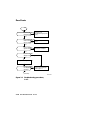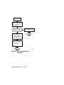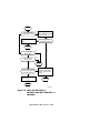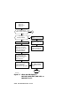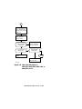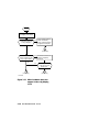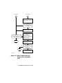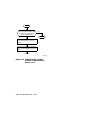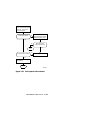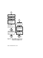
1
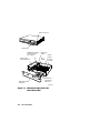
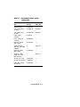
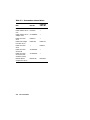
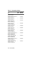
EK-PM32E-PS-001
DECstation 5000 Model
100 Series Pocket
Service Guide
digital equipment corporation
maynard, massachusetts
August 1991
The information in this document is subject
to change without notice and should not be
construed as a commitment by Digital Equipment
Corporation. Digital Equipment Corporation
assumes no responsibility for any errors that may
appear in this document.
The software described in this document is
furnished under a license and may be used or
copied only in accordance with the terms of such
license.
Digital Equipment Corporation assumes no
responsibility for the use or reliability of its
software on equipment that is not supplied by
Digital or its affiliated companies.
Copyright ©1990, 1991 Digital Equipment
Corporation
All Rights Reserved
Printed in U.S.A.
USA
This equipment generates, uses, and may emit
radio frequency energy. The equipment has
been type tested and found to comply with the
limits for a Class A computing device pursuant
to Subpart J of Part 15 of FCC Rules, which
are designed to provide reasonable protection
against such radio frequency interference.
Operation of this equipment in a residential
area may cause interference in which case the
user at his own expense will be required to take
whatever measures may be required to correct the
interference.
The following are trademarks of Digital Equipment
Corporation:
DEC
DECnet
DECstation
DECsystem
DECUS
MicroVAX
MicroVMS
PDP
ULTRIX
ULTRIX-32
UNIBUS
VAX
dt
VAXBI
VAXcluster
VAXstation
VMS
VT
Contents
Using This Guide . . . . . . . . . . .
xiii
Chapters
xv
..................
Conventions
..............
xvii
1 TROUBLESHOOTING
INFORMATION
Error Messages . . . . . . . . . .
Test failure messages . . .
Console exception
messages . . . . . . . . . . . . .
Memory test error
messages . . . . . . . . . . . . .
Addresses . . . . . . . . . . . . . . .
Slot numbers . . . . . . . . . .
Memory addresses . . . . . .
Hardware physical
addresses . . . . . . . . . . . . .
ULTRIX Error Logs . . . . . .
1–2
1–3
1–6
1–7
1–8
1–8
1–9
1–10
1–12
iii
Memory parity error log
fields . . . . . . . . . . . . . . . . .
CPU write timeout . . . . .
Bus timeout . . . . . . . . . . .
Diagnostic LEDs . . . . . . . . .
Registers . . . . . . . . . . . . . . .
Cause register . . . . . . . . .
System registers . . . . . . .
1–13
1–14
1–14
1–15
1–16
1–16
1–18
2 TROUBLESHOOTING TOOLS
Self-tests . . . . . . . . . . . . . . .
2–1
Console Mode Tests . . . . . . .
2–2
Console commands . . . . .
2–2
t command . . . . . . . . . . . .
2–4
SCSI controller (cntl)
test . . . . . . . . . . . . . . .
2–8
SCSI send diagnostics (sdiag)
test . . . . . . . . . . . . . . .
2–9
External loopback
test . . . . . . . . . . . . . . .
2–10
Transmit and receive
test . . . . . . . . . . . . . . .
2–12
SCC pins test . . . . . . .
2–14
Test scripts . . . . . . . . . . . .
2–17
Flow Charts . . . . . . . . . . . . .
2–18
3 PART NUMBERS
iv
Figures
2-1
2-2
2-3
2-4
2-5
2-6
2-7
2-8
2-9
2-10
2-11
Troubleshooting procedure,
1 of 2 . . . . . . . . . . . . . . .
2–18
Troubleshooting procedure,
2 of 2 . . . . . . . . . . . . . . .
2–19
When the LED display
is 1111 1111, 0011
1111, 0011 1110,
or 0011 1101, 1 of 2 . . .
2–20
When the LED display
is 1111 1111, 0011
1111, 0011 1110,
or 0011 1101, 2 of 2 . . .
2–21
When the LED display is
0011 0110 . . . . . . . . . . .
2–22
When the LED display
is 0010 0011, 0001 0011,
0000 0011, or 0000
0000 . . . . . . . . . . . . . . .
2–23
When the LED display
is 0011 1011, 0010 1011,
0001 1011, or 0000 1011, 1 of
2 ..................
2–24
When the LED display
is 0011 1011, 0010 1011,
0001 1011, or 0000 1011, 2 of
2 ..................
2–25
When the monitor has no
display, 1 of 2 . . . . . . . .
2–26
When the monitor has no
display, 2 of 2 . . . . . . . .
2–27
When hardware does not
appear in the cnfg display, 1 of
3 ..................
2–28
v
2-12
2-13
2-14
2-15
2-16
2-17
2-18
2-19
2-20
2-21
2-22
2-23
2-24
2-25
vi
When hardware does not
appear in the cnfg display, 2 of
3 ..................
2–29
When hardware does not
appear in the cnfg display, 3 of
3 ..................
2–30
Troubleshooting memory
modules . . . . . . . . . . . .
2–31
Troubleshooting SCSI
controllers and devices, 1 of
2 ..................
2–32
Troubleshooting SCSI
controllers and devices, 2 of
2 ..................
2–33
Troubleshooting an Ethernet
controller, 1 of 2 . . . . . .
2–34
Troubleshooting an Ethernet
controller, 2 of 2 . . . . . .
2–35
Troubleshooting a printer,
modem, or other serial line
device, 1 of 2 . . . . . . . . .
2–36
Troubleshooting a printer,
modem, or other serial line
device, 2 of 2 . . . . . . . . .
2–37
Troubleshooting the power
supply . . . . . . . . . . . . . .
2–38
If the system unit
overheats . . . . . . . . . . .
2–39
Troubleshooting the keyboard
and mouse, 1 of 2 . . . . .
2–40
Troubleshooting the keyboard
and mouse, 2 of 2 . . . . .
2–41
When ULTRIX is running but
the monitor has no display, 1 of
3 ..................
2–42
2-26
2-27
3-1
When ULTRIX is running but
the monitor has no display, 2 of
3 ..................
2–43
When ULTRIX is running but
the monitor has no display, 3 of
3 ..................
2–44
DECstation 5000 Model 100
Series Major FRUs . . .
3–2
Tables
1-1
1-2
1-3
1-4
1-5
1-6
1-7
1-8
1-9
1-10
2-1
2-2
2-3
Base system test error
messages . . . . . . . . . . .
1–4
Slot numbers in commands and
messages . . . . . . . . . . .
1–8
Memory module slot address
ranges . . . . . . . . . . . . . .
1–9
Hardware physical
addresses . . . . . . . . . . .
1–10
Error log event
types . . . . . . . . . . . . . . .
1–12
LED error codes . . . . . .
1–15
Cause register exception
codes . . . . . . . . . . . . . . .
1–17
System registers . . . . .
1–18
Memory Error Register (MER)
0x0C400000 . . . . . . . . .
1–19
System Interrupt Register
(SIR) 0x1C040110 . . . .
1–20
Console command
functions . . . . . . . . . . . .
2–2
Base system module tests and
utilities . . . . . . . . . . . . .
2–5
SCSI controller error
codes . . . . . . . . . . . . . . .
2–8
vii
2-4
2-5
2-6
2-7
2-8
3-1
3-2
3-3
3-4
3-5
3-6
3-7
3-8
viii
SCSI send diagnostics
error codes and
descriptions . . . . . . . . .
2–9
External loopback test codes
and descriptions . . . . . .
2–11
SCC transmit and
receive test codes and
descriptions . . . . . . . . .
2–13
Pin pairs tested by loopback
connectors . . . . . . . . . . .
2–15
SCC pins test codes and
descriptions . . . . . . . . .
2–16
Part numbers: Basic system
components . . . . . . . . .
3–3
Part numbers: Internal
drives . . . . . . . . . . . . . .
3–4
Part numbers: TURBOchannel
option modules . . . . . . .
3–5
Part numbers:
Monitors . . . . . . . . . . . .
3–6
Part numbers: Input
devices . . . . . . . . . . . . .
3–8
Part numbers: Loopback
connectors, plugs, test media,
and small hardware . .
3–9
Part numbers: Cords, cables,
and connectors . . . . . . .
3–10
Part numbers: Hardware
documentation . . . . . . .
3–12
Using This Guide
This guide contains the information that you
need for field maintenance of the DECstation
5000 Model 100 Series RISC workstation. Field
maintenance consists of identifying and replacing
failed field replaceable units (FRUs).
xiii
Chapters
This guide contains the following chapters:
Chapter 1
Troubleshooting Information
Chapter 2
Troubleshooting Tools
Chapter 3
Part Numbers
Chapter 1, Troubleshooting Information, describes
the types of information that help you identify
failed FRUs. The types of troubleshooting
information are:
Error messages
Addresses
ULTRIX error logs
Diagnostic LEDs
Registers
xv
Chapters
Some of the troubleshooting information is
automatically displayed, by the system, such
as exception messages and diagnostic LEDs.
Other information must be specifically generated
or accessed by the engineer, such as test error
messages, ULTRIX error logs, and registers.
Chapter 2, Troubleshooting Tools, describes the
tools that you use to test the system and its
components. The troubleshooting tools are:
Self tests
Console tests
Test scripts
Troubleshooting flowcharts
Chapter 3, Part Numbers, contains tables listing
the part numbers for the following types of
components:
Basic system components
Internal drives
TURBOchannel option modules
Monitors
Input devices
Cords, cables, and connectors
Loopback connectors, plugs, test media, and
small hardware
Hardware documentation
xvi
Conventions
This guide uses the following conventions:
Monospace
type
Anything that appears
on your monitor screen
is set in monospace
type, like this.
Boldface type
Anything you are asked to
type is set in boldface type,
like this.
Italic type
Any part of a command that
you replace with an actual
value is set in italic type, like
this.
xvii
1
TROUBLESHOOTING
INFORMATION
TROUBLESHOOTING INFORMATION 1–1
Error Messages
An error message can be either an exception
message that is automatically displayed when
something goes wrong during normal system
operation or a test failure message that is
displayed when an automatic or user-initiated
test fails.
This section describes the following error message
types:
Test failure messages
Console exception messages
Memory test error messages
1–2 TROUBLESHOOTING INFORMATION
Test failure messages
The test failure message format is:
?TFL slot_number/test_name
(n:description)[module]
Identifies a test error message
?TFL
slot_number Identifies the module that
reported the error
test_name
n
The test that failed
Indicates which part of the test
failed
description Describes the failure
module
The module identification
number
Table 1-1 lists the test values that can appear in
the test failure message when some component
part of the base system (slot number 3) fails. The
table also lists the recommended corrective action.
For information about test names and corrective
action when a TURBOchannel option module fails
(slot number 0, 1, or 2), refer to the documentation
for the indicated module.
TROUBLESHOOTING INFORMATION 1–3
Table 1-1 Base system test error messages
Component
Tested
Corrective
Action
cache/data
cache/fill
cache/isol
cache/reload
cache/seg
fpu
CPU module
Replace the
CPU module.
If the problem
persists,
replace the
system module.
mem
mem/float10
Memory
modules
Troubleshoot
according to
Figure 2-14.
mem/select
Memory and
system module
Replace the
memory
module failed.
If the problem
persists,
replace the
system module.
misc/halt
System module
Replace the
system module.
misc/kbd
Keyboard and
system module
Troubleshoot
according to
Figure 2-23.
misc/mouse
Mouse and
system module
Troubleshoot
according to
Figure 2-23.
misc/pstemp
Power supply
Troubleshoot
according to
Figure 2-21.
misc/wbpart
Memory
modules
Troubleshoot
according to
Figure 2-14.
Test Name
1–4 TROUBLESHOOTING INFORMATION
Table 1-1 (Cont.) Base system test error
messages
Component
Tested
Corrective
Action
ni/cllsn
ni/common
ni/crc
ni/cntrs
ni/dma1
ni/dma2
line>ni/esar
ni/ext-lb
ni/int
ni/int-lb
ni/m-cst
ni/promisc
ni/regs
ni/setup
Base system
Ethernet
controller
Troubleshoot
according to
Figure 2-17.
rtc/nvr
rtc/period
rtc/regs
rtc/time
System module
Replace the
system module.
scc/access
scc/enable
scc/io
scc/regs
scc/pins
scc/tx-rx
Serial line
controllers and
devices attached
to them
Troubleshoot
according to
Figure 2-19.
scsi/cntl
scsi/sdiag
scsi/target
Base system
SCSI controller
or device
Troubleshoot
according to
Figure 2-15.
tlb/prb
tlb/reg
CPU module
Replace the
CPU module.
Test Name
TROUBLESHOOTING INFORMATION 1–5
Console exception messages
This is a typical console exception message:
? PC:
? CR:
? SR:
0x451<vtr=nrml>
0x810<ce=0,ip4,exc=AdEL>
0x30030000
<cu1,cu0,cm,ipl=8>
? VA: 0x451
? ER: 0x100003f0
? MER: 0x2000
PC
CR
The address of the exception instruction
The contents of the cause register. The last
term is the exception type. The exception
types are as follows:
MOD, TLBL, or TLBS: An invalid address
was probably used in a console command.
AdEL or AdES: A console command
probably attempted access on a boundary
that was not a word.
IBE or DBE: Timeout bus error if MER
bits 16, 15, 11, 10, 9, and 8 are all clear.
Memory error if one or more of those MER
bits is set.
SR
VA
ER
MER
The contents of the status register
The virtual address of the exception
The contents of the error address register
The contents of the memory error register
1–6 TROUBLESHOOTING INFORMATION
Memory test error messages
This is a typical memory test error message:
?TFL:3/mem(PER,cause=0000001C,
DBE=0040000c,
Bank 2, D16-31,d23-d16)
Bank
The slot number of the problem
memory module
D16-31
The module farthest from the power
supply failed.
D0-15
The module nearest the power supply
failed.
TROUBLESHOOTING INFORMATION 1–7
Addresses
Slot numbers
Table 1-2 Slot numbers in commands and
messages
Slot
No.
Hardware Identified
0
Option module in slot 0
(farthest from the power supply)
1
Option module in slot 1
(middle option slot)
2
Option module in slot 2
(nearest the power supply)
3
Base system hardware, which includes
-
System module
CPU module
Memory modules
Base system SCSI controller
Base system Ethernet controller
1–8 TROUBLESHOOTING INFORMATION
Memory addresses
These addresses appear in memory error
printouts.
Table 1-3 Memory module slot address
ranges
Slot
No.
2-Mbyte Module
Addresses
8-Mbyte Module
Addresses
0
0000000-03FFFFF
0000000-0FFFFFF
1
0400000-0FFFFFF
1000000-1FFFFFF
2
0800000-0FFFFFF
2000000-2FFFFFF
3
0C00000-0FFFFFF
3000000-3FFFFFF
4
1000000-1FFFFFF
4000000-4FFFFFF
5
1400000-1FFFFFF
5000000-5FFFFFF
6
1800000-1FFFFFF
6000000-6FFFFFF
7
1C00000-1FFFFFF
7000000-7FFFFFF
TROUBLESHOOTING INFORMATION 1–9
Hardware physical addresses
These addresses appear in error printouts.
Table 1-4 Hardware physical addresses
Address Range
Indicated
Hardware
0x00000000-0x07FFFFFF
Memory array
banks 0 to 7
0x08000000-0x0BFFFFFF
Reserved
0x0C000000-0x0DFFFFFF
Memory registers
0x0E000000-0x0FFFFFFF
CPU control ASIC
registers
0x10000000-0x13FFFFFF
Slot 0,
option module
0x14000000-0x17FFFFFF
Slot 1,
option module
0x18000000-0x1BFFFFFF
Slot 2,
option module
1–10 TROUBLESHOOTING INFORMATION
Table 1-4 (Cont.) Hardware physical
addresses
Address Range
Indicated
Hardware
0x1C000000-0x1FFFFFFF
Base system, slot 3
in commands and
messages, includes
the elements listed
below
0x1C000000-0x1C03FFFF
System ROM
0x1C040000-0x1C07FFFF
I/O control registers
and DMA pointers
0x1C080000-0x1C0BFFFF
Ethernet address
PROM
0x1C0C0000-0x1C0FFFFF
Ethernet interface
0x1C100000-0x1C13FFFF
SCC(0) registers
0x1C140000-0x1C17FFFF
Reserved
0x1C180000-0x1C1BFFFF
SCC(1) registers
0x1C1C0000-0x1C1FFFFF
Reserved
0x1C200000-0x1C23FFFF
Real-time clock
0x1C240000-0x1C29FFFF
Reserved
0x1C300000-0x1C33FFFF
SCSI interface
0x1C340000-0x1C37FFFF
Reserved
0x1C380000-0x1C3BFFFF
SCSI DMA
0x1C3C0000-0x1FBFFFFF
Reserved
0x1FC00000-0x1FC3FFFF
Boot ROM
0x1FC40000-0x1FFFFFFF
Reserved
TROUBLESHOOTING INFORMATION 1–11
ULTRIX Error Logs
To examine the ULTRIX error logs from the
ULTRIX prompt, type
/etc/uerf -R | more
Table 1-5 Error log event types
Code
Event Type
100
Machine check
101
Memory error
102
Disk error
103
Tape error
104
Device controller error
105
Adapter error
106
Bus error
107
Stray interrupt
108
Asynchronous write error
109
Exception or fault
113
CPU error and status information
130
Error and status registers
200
Panic (bug check)
250
Informational ASCII message
251
Operational message
300
System startup message
310
Time change message
350
Diagnostic information
Error log information varies by event type. The
following lists cover three typical event types:
memory parity error, CPU write timeout, and bus
timeout.
1–12 TROUBLESHOOTING INFORMATION
Memory parity error log fields
The following memory error log fields are pertinent
when a memory parity error occurs:
The ERROR SYNDROME field identifies the
memory parity error.
The MEM REG fields give the following memory
failure information:
HARD CNT shows how many errors recurred
on both read and write operations.
SOFT CNT shows how many errors recurred
on read but cleared on write.
TRAN CNT shows how many errors did not
recur on read.
DATA BIT IN ERROR or PARITY BIT
IN ERROR indicates whether a data bit or a
parity bit failed.
HIGH BYTE IN ERROR or LOW BYTE IN
ERROR identifies the byte where the error
occurred.
MEMORY PARITY ERROR lists the error
type (hard, soft, transient).
D0-15 or D16-31 tells whether the low
(left) or high (right) SIMM failed.
BANK tells which bank of memory failed.
The PHYSICAL ADDRESS field identifies the
block being read at failure.
TROUBLESHOOTING INFORMATION 1–13
CPU write timeout
The following error and status register error log
fields are pertinent when a CPU write timeout
occurs:
OS EVENT TYPE refers to the error and status
registers for a CPU write timeout.
PANIC MESSAGE indicates a CPU write timeout.
The CAUSE register gives no information for a
CPU write timeout.
The BAD VIRT ADR register identifies the
address of the timeout.
The
SIR register shows the write timeout error.
Bus timeout
The following error and status register error log
fields are pertinent when a bus timeout occurs:
OS EVENT TYPE refers to the error and status
registers for a bus timeout.
PANIC MESSAGE indicates a bus timeout.
The CAUSE register tells that the error occurred
during data load or store.
The BAD VIRT
the timeout.
ADR register tells the address of
1–14 TROUBLESHOOTING INFORMATION
Diagnostic LEDs
Table 1-6 LED error codes
LED
Error Code
(1=On)
Troubleshooting Procedure
1111 1111
0011 1111
0011 1110
0011 1101
Troubleshoot according to
Figure 2-3.
0011 0111
Replace the CPU module. If the
LEDs display 0011 0111 when the
power-up self-test stops, replace
the system module.
0011 0110
Troubleshoot according to
Figure 2-5.
0010
0001
0000
0000
0011
0011
0011
0000
Troubleshoot according to
Figure 2-6.
0011 1011
0010 1011
0001 1011
0000 1011
Troubleshoot according to
Figure 2-7.
TROUBLESHOOTING INFORMATION 1–15
Registers
There are two types of registers: CPU registers
and system registers. CPU register information
is automatically displayed on the screen when an
exception occurs. To access system registers from
the console prompt (>>), enter the e command.
Cause register
The cause register is a CPU register and is
displayed in exception error messages only. You
cannot access the cause register independently.
The cause register has the following format:
31 30 29 28 27
16
+----+---+-----+-----------------+
| BD | 0 | CE |
0
|
+----+---+-----+-----------------+
1
1
2
12
15
8 7 6 5
2 1 0
+------------+----+---------+----+
|
IP
| 0 | ExcCode | 0 |
+------------+----+---------+----+
8
2
4
2
BD = 1
Indicates that the last exception
occurred in a branch delay slot
CE
The coprocessor unit number
reference for a coprocessor unusable
exception
IP = 1
Indicates that an interrupt is pending
ExcCode
Shows the exception code. See
Table 1-7.
0
Reserved.
1–16 TROUBLESHOOTING INFORMATION
Table 1-7 Cause register exception codes
Number
Mnemonic
Description
0
Int
Interrupt
1
Mod
TLB modification
exception
2
TLBL
TLB miss exception (load
or instruction fetch)
3
TLBS
TLB miss exception
(store)
4
AdEL
Address error exception
(load or instruction fetch)
5
AdES
Address error exception
(store)
6
IBE
Bus error exception
(instruction fetch)
7
DBE
Bus error exception (data
reference: load or store)
8
Sys
Syscall exception
9
Bp
Breakpoint exception
10
RI
Reserved instruction
exception
11
CpU
Coprocessor unusable
exception
12
OV
Arithmetic overflow
exception
13-15
Reserved
TROUBLESHOOTING INFORMATION 1–17
System registers
To examine a system register from the console
prompt (>>), enter the e command:
e [options] [console_address]
Table 1-8 System registers
Register
Console
Address
Description
SSR
0xBC040100
System support register
MER
0xAC400000
Memory error register
SIR
0xBC040110
System interrupt
register
Mask
0xBC040120
System interrupt mask
register
MSR
0xAC800000
Memory size register
EAR
0xAE000004
Error address register
1–18 TROUBLESHOOTING INFORMATION
Table 1-9 Memory Error Register (MER)
0x0C400000
Bits
Access
31:17
Description
Reserved
16
R/W
Page boundary error
15
R/W
Transfer length error
14
R/W
PARDIS memory error
disable
13:12
11:8
7:0
Reserved
R/W
Byte(s) with parity error
Reserved
TROUBLESHOOTING INFORMATION 1–19
Table 1-10 System Interrupt Register (SIR)
0x1C040110
Bits
Access Description
31
R/W0C
Comm port 1 transmit page end
interrupt
30
R/W0C
Comm port 1 transmit DMA
memory read error
29
R/W0C
Comm port 1 receive half page
interrupt
28
R/W0C
Comm port 1 receive DMA page
overrun
27
R/W0C
Comm port 2 transmit page end
interrupt
26
R/W0C
Comm port 2 transmit DMA
memory read error
25
R/W0C
Comm port 2 receive half page
interrupt
24
R/W0C
Comm port 2 receive DMA overrun
23
R/W0C
Reserved
22
R/W0C
Reserved
21
R/W0C
Reserved
20
R/W0C
Reserved
19
R/W0C
SCSI DMA interrupt (DMA buffer
pointer loaded)
18
R/W0C
SCSI DMA overrun error
17
R/W0C
SCSI DMA memory read error
16
R/W0C
LANCE DMA memory read error
15
R
Reserved
14
R
NVR mode jumper
13
R
Reserved
12
R
CPU I/O-write timeout interrupt
1–20 TROUBLESHOOTING INFORMATION
Table 1-10 (Cont.) System Interrupt Register
(SIR) 0x1C040110
Bits
Access Description
11
R
Reserved
10
R
NRMOD manufacturing mode
jumper
9
R
SCSI interrupt from 53C94 SCSI
controller
8
R
Ethernet interrupt
7
R
SCC(1) serial interrupt (comm port
2 and keyboard)
6
R
SCC(0) serial interrupt (comm port
1 and mouse)
5
R
TOY interrupt
4
R
PSWARN power supply warning
indicator
3
R
Reserved
2
R
SCSI data ready
1
R
PBNC
0
R
PBNO
Note
Comm port 1 is the same as serial line 2.
Comm port 2 is the same as serial line 3.
TROUBLESHOOTING INFORMATION 1–21
2
TROUBLESHOOTING
TOOLS
Self-tests
The system automatically runs a power-up
test sequence when you turn the power on.
The system runs a quick test or thorough test
sequence according to the value of the testaction
environtmental variable (q for quick, t for
thorough). Quick is for normal startup; thorough
for troubleshooting.
You can run a self-test sequence from the console
prompt without cycling system power.
For the quick test, type:
sh slot_number/pst-q
For the thorough test, type:
sh slot_number/pst-t
TROUBLESHOOTING TOOLS 2–1
Console Mode Tests
From the console prompt (>>), enter the t
command to run an individual test or the sh
command to run a test script.
Console commands
From the console prompt, enter ? to see a list of
available console commands and their formats.
Table 2-1 Console command functions
Command
Function
?[cmd]
Displays one or more
console commands and
formats
boot [-zseconds]
[-n][bootpath]
[-a][args...]
Boots the system
cat
slot_number/
script_name
Displays the contents
of a script
cnfg [slot_number]
Displays system
configuration
information
d [-( b | h | w)] [-Scount]
rng
Deposits data into
memory
e [-b | h | w] [-c] [-d]
[-o] [-u] [-x] [-Scount]
rng
Examines memory
contents
erl [-c]
Displays the error
message log
go [address]
Transfers control to a
specific address
init [slot_number] [-m]
Resets the system or a
module
2–2 TROUBLESHOOTING TOOLS
Table 2-1 (Cont.) Console command
functions
Command
Function
ls [slot_number]
Displays the scripts
and other files in a
module
passwd [-c] [-s]
Sets and clears the
console password
printenv [variable]
Prints environment
variables
restart
Attempts to restart the
operating system
software that is
specified in the restart
block
script name
Creates a temporary
script of console
commands
setenv variable value
Sets an environment
variable
sh [-b] [-e] [-l] [-v] [-S]
[slot_number/script]
[arg...]
Runs a script
t [-l]
slot_number/test_name
[arg1]...[argn]
Runs a test
test
Runs a comprehensive
test script that checks
the system hardware
unsetenv variable
Removes an environment variable
TROUBLESHOOTING TOOLS 2–3
t command
To run a single test from the console prompt type
t [-l] slot_number/test_name [arg1] [...] [argn]
t
is the test command.
-l
The test repeats until you press
Ctrl-c or reset the system with the
init command or by cycling power.
slot_number
Replace with the slot number of
the module to be tested.
test_name
Replace with the name of the test
to be run.
arg1...argn
Specify individual test conditions.
Table 2-2 lists the tests for the base system
modules. To display a list of tests for an option
module from the console prompt (>>), type
t slot_number/?
2–4 TROUBLESHOOTING TOOLS
Table 2-2 Base system module tests and
utilities
Test or Utility
Command
System module tests:
Halt button
t 3/misc/halt [number]
Nonvolatile RAM (NVR)
t 3/rtc/nvr [pattern]
Overheat detect
t 3/misc/pstemp
Real-time clock period
t 3/rtc/period
Real-time clock register
t 3/rtc/regs
Real-time
t 3/rtc/time
Serial communication
chip (SCC) access
t 3/scc/access
Serial communication
chip (SCC) DMA
t 3/scc/dma [line]
[loopback] [baud]
SCC interrupts
t 3/scc/int [line]
SCC I/O
t 3/scc/io [line]
[loopback]
SCC pins
t 3/scc/pins [line]
[loopback]
SCC transmit and
receive
t 3/scc/tx-rx [line]
[loopback] [baud]
TROUBLESHOOTING TOOLS 2–5
Table 2-2 (Cont.) Base system module tests
and utilities
Test or Utility
Command
CPU module tests:
Cache data
t 3/cache/data [cache]
[address]
Cache fill
t 3/cache/fill [cache]
[offset]
Cache isolate
t 3/cache/isol [cache]
Cache reload
t 3/cache/reload
[cache] [offset]
Cache segment
t 3/cache/seg [cache]
[address]
CPU-type utility
t 3/misc/cpu-type
Floating-point unit
t 3/fpu
Translation lookaside
buffer (TLB) probe
t 3/tlb/prb
TLB registers
t 3/tlb/reg [pattern]
Memory module tests:
Floating 1/0 memory
t 3/mem/float10
[address]
Memory module
t 3/mem [module]
[threshold] [pattern]
RAM address select
lines
t 3/mem/select
Partial write
t 3/misc/wbpart
Zero memory utility
t 3/mem/init
2–6 TROUBLESHOOTING TOOLS
Table 2-2 (Cont.) Base system module tests
and utilities
Test or Utility
Command
Base system Ethernet controller tests:
Collision
t 3/ni/cllsn
Cyclic redundancy code
(CRC)
t 3/ni/crc
Display MOP counters
utility
t 3/ni/ctrs
Ethernet-DMA registers
t 3/ni/dma1
Ethernet-DMA transfer
t 3/ni/dma2
Ethernet station address
ROM (ESAR)
t 3/ni/esar
External loopback
t 3/ni/ext-lb
Internal loopback
t 3/ni/int-lb
Interrupt request (IRQ)
t 3/ni/int
Multicast
t 3/ni/m-cst
Promiscuous mode
t 3/ni/promisc
Registers
t 3/ni/regs
Base system SCSI controller and drives tests:
SCSI controller
t 3/scsi/cntl
SCSI send diagnostics
t 3/scsi/sdiag scsi_id
[d] [u] [s]
SCSI target
t 3/scsi/target scsi_id
[w] [lloops]
Keyboard and mouse tests:
Keyboard
t 3/misc/kbd
Mouse
t 3/misc/mouse
TROUBLESHOOTING TOOLS 2–7
SCSI controller (cntl) test
To test the operation of a SCSI controller from the
console prompt, enter
t slot_number/scsi /cntl
Table 2-3 SCSI controller error codes
(code: description)
Meaning
(1: rd cnfg)
Values written to and
read from configuration
register did not match.
(2: fifo flg)
First in, first out (FIFO)
load and FIFO flags did
not match.
(3: cnt xfr)
Write and read operation
on TCL register reported
a mismatch.
(4: illg cmd)
Command was illegal
and did not generate an
interrupt.
(5: int reg)
Controller cannot clear
internal interrupt
register.
(6: rd cnfg)
Mismatch occurred when
reading the write/read
configuration register.
2–8 TROUBLESHOOTING TOOLS
SCSI send diagnostics (sdiag) test
To run the self-test for an individual SCSI device
from the console prompt, enter
t slot_number/scsi /sdiagscsi_id [d] [u] [s]
Table 2-4 SCSI send diagnostics error
codes and descriptions
(code: description)
Meaning
(1: dev ol)
Test could not bring the
unit on line.
(2: dev ol)
Test could not bring the
unit on line.
(3: sdiag)
Device failed the send
diagnostics test.
TROUBLESHOOTING TOOLS 2–9
External loopback test
To check an Ethernet controlleer and its
connections from the console prompt, install
a ThickWire loopback connector and enter the
following command:
t slot_number /ni /ext-lb
2–10 TROUBLESHOOTING TOOLS
Table 2-5 External loopback test codes
and descriptions
(code: description)
Meaning
(1: (LANCE-init
[xxxxxxxx]))
LANCE initialization
failed. xxxxxxxx is a
LANCE failure code.
(3: (xmit [xxxxxxxx,
yyyyyyyy] zzzzz))
LANCE initialization failed.
xxxxxxxx,yyyyyyyy
is a LANCE failure
code. zzzzz describes
the likely cause of
the failure.
(4: rcv [xxxxxxxx,yyyyyyyy])
System did not
receive packet.
xxxxxxxx, yyyyyyyy
describes the receive
failure.
(6: pkt-data !=)
Transmitted packet
was not received.
(7)
Fatal error occurred.
TROUBLESHOOTING TOOLS 2–11
Transmit and receive test
To test the transmit and receive function of a
serial port from the console prompt (>>), install a
communications adapter with an MMJ loopback
connector and enter the following command:
t 3/scc/tx-rx [line] line loopback [baud] [parity]
[bits]
line
Specify line 0, 1, 2, or 3.
loopback
Specify intl for internal or extl for
external.
baud
Specify 300, 1200, 2400, 3600,
4800, 9600, 19200, or 38400.
parity
Specify none, odd, or even.
bits
Specify 8, 7, or 6 bits per
character.
2–12 TROUBLESHOOTING TOOLS
Table 2-6 SCC transmit and receive test
codes and descriptions
(code: description)
Meaning
1: LnN tx bfr not
empty. status=xx
System could not write a
single character because
the transmit buffer was
not empty. The error
occurred on line N. xx is
the contents of SCC read
register 0.
2: LnN char not rcvd.
status=xx
Expected CHAR AVAIL
signal not received. The
error occurred on line N.
xx is the contents of SCC
read register 0.
3: LnN expctd=xx,
rcvd=yy, status=zz
The character received
was different from the
character transmitted.
The error occurred
on line N. xx is the
transmitted value. yy is
the received value. zz is
the contents of SCC read
register 0.
4: LnN Rx err. errs=xx
Receiving character
in FIFO reported
an error. The error
occurred on line N. xx
is the associated input
character FIFO error
bits.
TROUBLESHOOTING TOOLS 2–13
SCC pins test
To test the pins on a communications connector
from the console prompt, install a modem loopback
connector on the communications connector and
enter the following command:
t 3/scc/pins line attachment
line
Specify line 2 (right connector) or
3 (left).
attachment
Identify the loopback connector:
29-24795, H8571, hm, or H3200
2–14 TROUBLESHOOTING TOOLS
Table 2-7 Pin pairs tested by loopback
connectors
Loopback
Connector
Pin Pairs
Tested
29-24795
4-5
23-6-8
RTS to CTS
SS to DSR and CD
6-23 failure implies 6
broken.
8-23 failure implies 8
broken.
6-23 8-23 failure
implies 23 broken.
H3200
4-5
6-20
12-23
RTS to CTS
DSR to DTR
SI to SS
H8571-A
4-5
20-6-8
RTS to CTS
DTR to DSR and CD
6-20 failure implies 6
broken.
8-20 failure implies 8
broken.
6-20 8-20 failure
implies 20 broken.
hm
(H8571-A)
4-5
RTS to CTS
Meaning
TROUBLESHOOTING TOOLS 2–15
Table 2-8 SCC pins test codes and
descriptions
(code: description)
Meaning
1:LnN Invld param [xx]
The loopback
specifier was invalid.
The error occurred
on serial line N.
xx is the first two
characters of the
invalid value.
2:LnN Strtup R-xx
xptd=yy actl=zz | pins |
Test failed to
generate the expected
SCC status bits.
The error occurred
on serial line N. xx
is the number of
the SCC register
that contains the
status bits. yy is the
expected status bits.
zz is the actual status
bits. | pins | is the
pin pairs tested.
3: LnN xxxxx
Pins failed to respond
properly. xxxxx is the
numbers of one or
more pin pairs that
failed the test.
2–16 TROUBLESHOOTING TOOLS
Test scripts
To run a test script from the console prompt (>>),
type
sh [options] slot_number/test_name
sh
The shell command
options:
-b
Executes script directly, not
through a subshell
-e
Script halts on error.
-l
Test loops until Ctrl-c or system
reset.
-v
Echos script to console
-S
Suppresses script-not-found error
messages
slot_number
Replace with the slot number of
the module to be tested.
test_name
Replace with the name of the
script to be run.
To see a list of all test scripts for a module, type
ls slot_number/?
TROUBLESHOOTING TOOLS 2–17
Flow Charts
Start
See Figure 2-21,
Does the powerNo
supply"Troubleshooting the power
LED glow green?
supply."
Yes
Do the diagnostic
NoLEDs
flicker but not count See Table 1-6, "LED error
down to 0000 0000? codes."
Yes
Does a display No
See Figure 2-9, "When the
appear on the monitor?monitor has no display."
Yes
Yes
Does the monitor
display an error message?
No
Type
test
; press Return.
Does the monitor
Yes
now display an error See the "Error Messages"
section, page 1-1.
message?
No
(continued)
Figure 2-1 Troubleshooting procedure,
1 of 2
2–18 TROUBLESHOOTING TOOLS
WS33P002
2–19
-12.
or
WS33P003
110,
odule.
WS33P005
2–21
110,
LEDs = 0011 0110
Insert two good memory
modules into slot 0 and at
least 8 Mbytes of memory
total in the system.
Does the power-up
self-test still stop and the
LEDs display 0011 0110?
Yes
Replace the system module.
No
Replace the remaining
memory modules one
pair at a time. After each
pair, type 3/mem and the
slot number. Press Return.
End
Replace any modules that
report an error after the
memory test. See
"Memory Test Error
Messages".
End
WS33P007
Figure 2-5 When the LED display is
0011 0110
2–22 TROUBLESHOOTING TOOLS
Start
Do the left LEDs
display 0010 or 0001?
Replace the option
module.
No
Yes
Find the option module in
the slot number displayed
on the left LEDs.
No
Is it a 2D graphics
accelerator module?
End
Do the left LEDs
display 0000?
Yes
No
Yes
Do the right LEDs
display 0000?
Yes
No
Is the option module Yes
in slot 0 a 2D graphics
accelerator module?
End
Replace the 2D module
VSIMM. If the problem
persists, replace the 2D
module.
No
Replace the option
module in slot 0.
End
End
WS33P017
Figure 2-6 When the LED display is
0010 0011, 0001 0011, 0000 0011, or
0000 0000
TROUBLESHOOTING TOOLS 2–23
LEDs = 0011 1011,
0010 1011,
0001 1011, or
0000 1011
Is a TURBOchannel
graphics module installed?
No
A
Yes
Is a VT320
terminal available?
No
Replace the graphics
module.
Yes
Remove all graphics modules.
Turn on the system unit
power.
Connect the VT320 to the
system unit. Turn on the
VT320 and the system unit.
On the VT320 keyboard,
type setenv console s.
Troubleshoot according to
the error messages that
appear on the monitor.
Turn off the system unit
power. Reinstall the graphics
module(s). Turn on the
system unit power.
Troubleshoot according to
the error messages that
appear on the VT320.
Replace FRUs as appropriate.
On the VT320 keyboard,
type setenv console *
to re-enable the normal
monitor.
End
WS33P026
Figure 2-7 When the LED display is
0011 1011, 0010 1011, 0001 1011, or
0000 1011, 1 of 2
2–24 TROUBLESHOOTING TOOLS
A
Turn off the system unit
power. Disconnect the
VT320 terminal from the
system unit.
Turn on the system unit
power. Check the
diagnostic LEDs.
Does the power-up
self-test complete
successfully?
Yes
The terminal or cable
is faulty. Isolate and
replace the bad part.
No
Is the right LED
display 1011?
No
Is the right LED
display 0000?
Yes
Yes
Replace the system
module.
End
No
Troubleshoot according
to the LED codes.
WS33P027
Figure 2-8 When the LED display is
0011 1011, 0010 1011, 0001 1011, or
0000 1011, 2 of 2
TROUBLESHOOTING TOOLS 2–25
P010
ower
2–27
3P011
Start
Type cnfg, press Return.
Type cnfg 3, press Return.
Is a memory module
missing from the cnfg
or cnfg 3 display?
Yes
Look for missing memory
module. Reseat any
memory module(s) that do
not appear in the display.
No
C
(Continued)
Is a SCSI controller or
device missing from the
cnfg or cnfg 3 display?
No
Yes
Yes
Check that the first device
in the bus is properly
connected.
Does the bus appear
in the cnfg or cnfg 3
display now?
No
A
B
(Continued)
(Continued)
WS33P008
Figure 2-11 When hardware does not
appear in the cnfg display,
1 of 3
2–28 TROUBLESHOOTING TOOLS
(Continued)
(Continued)
A
B
Replace the cable from the
SCSI controller to the first
device.
No
Is the SCSI controller or
device still missing from
the display?
Yes
Replace the SCSI controller.
Is a SCSI device
missing from the cnfg or
cnfg 3 display?
Yes
No
End
Make sure the power is on
and all cables are
connected properly.
Change the SCSI ID for the
missing device to an
unused ID between 0 and 6.
Type init slot number.
Press Return.
Yes
End
Does the device
appear in the cnfg or cnfg3
display now?
No
Replace the drive.
WS33P009
Figure 2-12 When hardware does not
appear in the cnfg display,
2 of 3
TROUBLESHOOTING TOOLS 2–29
Start
Interpret any error messages
to determine which memory
modules reported an error.
No
Do all memory modules
report an error?
Replace those memory
modules that report an error.
Yes
Remove all the memory
modules.
Insert two good memory
modules in slot 0 and at
least 8 Mbytes of contiguous
memory total. Repeat the
memory test.
Does the memory test
still report an error?
Yes
Replace the system module.
No
Install any additional pairs of
memory modules one pair at
a time. Run the memory test
for each new pair of modules.
Replace any memory
modules that report an error.
End
WS33P006
Figure 2-14 Troubleshooting memory
modules
TROUBLESHOOTING TOOLS 2–31
Start
Type cnfg slot number.
Press Return.
Does the drive appear in
the cnfg display?
No
Check that all cables are
connected to the drive and
that there is a terminator on
the last external drive in the
bus.
Yes
Make sure each drive in the
SCSI bus has a unique ID
from 0 to 6.
(continued)
Type init slot number.
Press Return.
Yes
End
Does the drive appear in
the cnfg display now?
No
Replace the drive.
WS33P014
Figure 2-15 Troubleshooting SCSI controllers
and devices, 1 of 2
2–32 TROUBLESHOOTING TOOLS
(continued)
Does the cntl test report
an error?
Yes
Replace the SCSI controller
that has the slot number
that appears in the error
message.
No
Does the sdiag test report Yes
an error?
No
Troubleshoot according to
the sdiag test error
messages. See the SCSI
drive service guide.
End
Replace the SCSI controller Yes
in the slot number listed in
the error message.
Does the sdiag test still
report an error?
No
End
WS33P015
Figure 2-16 Troubleshooting SCSI controllers
and devices, 2 of 2
TROUBLESHOOTING TOOLS 2–33
e
es
2–35
3P021
e
error
he
s as
Start
Does an error message list
3/scc as the test that failed or does
the customer complain about a
specific serial line device?
Yes
No
End
Make sure the hardware and software
for the serial line device are set up
properly.
Run the internal loopback serial line test
script. Type sh 3/test-scc-t and press
Return.
(Continued)
WS33P018
Figure 2-19 Troubleshooting a printer,
modem, or other serial line
device, 1 of 2
2–36 TROUBLESHOOTING TOOLS
2–37
g to
WS33P004
Turn off the system unit
power. Remove the system
unit cover. Turn on the
system unit power.
Do any fans rotate?
No
If the fan assembly power
cord is connected correctly,
replace the power supply.
Yes
No
End
Do all three fans rotate?
Yes
Does the power
supply still overheat?
Yes
Replace the power supply.
No
Replace the power supply
fan assembly.
End
WS33P001
Figure 2-22 If the system unit overheats
TROUBLESHOOTING TOOLS 2–39
ard
P020
2–41
ard
P022
3
he
2–43
3
he
t
WS33P012
A
(Continued)
Connect the alternate
terminal to the system unit.
Type setenv console s.
Press Return.
B
Troubleshoot according to
the error messages that
appear on the terminal.
Replace any FRU that
reports an error.
Reconnect any SCSI
devices that you
disconnected. Reset the
environment variables.
End
Replace the TURBOchannel
module in the slot number
that appears on the left
LEDs.
(Continued)
Yes
Does the power-up
self-test stop with the
right LEDs equal to
0011 or 0010?
No
If the entire LED display is
0000 0000, replace parts of
the graphics hardware one
by one until the problem is
corrected.
Reconnect any SCSI
devices that you
disconnected. Reset the
environment variables.
End
End
WS33P013
Figure 2-27 When ULTRIX is running but the
monitor has no display, 3 of 3
2–44 TROUBLESHOOTING TOOLS
3
PART NUMBERS
PART NUMBERS 3–1
System unit cover
Bezel insert
TURBOchannel option
module connector
(one of three)
Power supply
and fan assembly
Removable media
drive panel
System unit
chassis
System
module
CPU
module
Memory
module
Locations for
internal hard
disk drives
WS33P028
Figure 3-1 DECstation 5000 Model 100
Series Major FRUs
3–2 PART NUMBERS
Table 3-1 Part numbers: Basic system
components
Item
Part No.
Customer
Order No.
System module
70-28336-01
—
CPU module only,
20 MHz
54-20615-01
KN02-BC
CPU module only,
25 MHz
54-20615-02
KN02-CC
Power supply
assembly
H7826-AA
—
Power supply fan
assembly
70-28334-01
—
Memory module,
2Mb, single
57-30735-02
—
Memory module,
4Mb pair, (two 2Mb
modules)
—
MS01-AA
Memory module,
8Mb, single
57-34320-01
—
Memory module,
16Mb pair (two
8Mb modules)
—
MS01-CA
System unit cover
70-28337-01
—
System unit chassis
70-28320-01
—
Removable media
drive panel
70-28338-01
—
PART NUMBERS 3–3
Table 3-2 Part numbers: Internal drives
Item
Part No.
Customer
Order No.
RX23 diskette drive
—
RX23-FL
RX23 diskette drive
unit
RX23-A0
—
RX23 diskette drive
adapter card
54-19288-01
—
RZ23 hard disk
drive
RZ23-E0
—
RZ23L half-height
hard disk drive
RZ23L-E0
RZ23L-FL
RZ24 hard disk
drive
—
RZ24-FL
RZ24 hard disk
drive PCB
29-28144-01
—
RZ24 hard disk
drive head disk
assembly (HDA)
29-28145-01
—
RRD42 optical
compact disc drive
RRD42-AA
RRD42-FL
3–4 PART NUMBERS
Table 3-3 Part numbers: TURBOchannel
option modules
Item
Part No.
Customer
Order No.
1-plane Monochrome 54-20609-01
Graphics Frame
Buffer (MFB)
PMAG-AB
8-plane Color
Graphics Frame
Buffer (CFB)
54-19815-01
PMAG-BB
8-plane 2D
54-20314-01
Graphics Accelerator
PMAG-CB
8-plane 3D
54-20185-01
Graphics Accelerator
PMAG-DB
24-plane 3D
54-20185-02
Graphics Accelerator
PMAG-EB
96-plane Highperformance 3D
Graphics
54-20114-01
PMAG-FB
8-to-24-plane
Upgrade
—
PMAG-GB
24-bit Z-buffer
Option Module
—
PMAG-HA
8-plane Z-buffer
54-20410-AA
—
16-plane Z-buffer
54-20352-AA
—
ThickWire Ethernet
Option Module
54-19874-01
PMAD-AB
SCSI Controller
Option Module
54-19876-01
PMAZ-AB
PART NUMBERS 3–5
Table 3-4 Part numbers: Monitors
Part
No.
Customer
Order No.
VR262, 19-inch monochrome
monitor, 120 volts
—
VR262-AA
VR262, 19-inch monochrome
monitor, 240 volts
—
VR262-A3
VR297, 16-inch color
monitor, 120 volts
—
VR297-DA
VR297, 16-inch color
monitor, 240 volts,
Northern Hemisphere
—
VR297-D3
VR297, 16-inch color
monitor, 240 volts,
Southern Hemisphere
—
VR297-D4
VR299, 19-inch color
monitor, 120 volts
—
VR299-DA
VR299, 19-inch color
monitor, 240 volts,
Northern Hemisphere
—
VR299-D3
VR299, 19-inch color
monitor, 240 volts,
Southern Hemisphere
—
VR299-D4
VR319, 19-inch monochrome
monitor, 120/240 volts,
Northern Hemisphere
—
VR319-DA
VR319, 19-inch gray-scale
monitor, 120/240 volts,
Northern Hemisphere
—
VR319-CA
VR319, 19-inch monochrome
monitor, 240 volts,
Southern Hemisphere
—
VR319-D4
VR319, 19-inch gray-scale
monitor, 240 volts,
Southern Hemisphere
—
VR319-C4
Item
3–6 PART NUMBERS
Table 3-4 (Cont.) Part numbers: Monitors
Part
No.
Customer
Order No.
VRT16, 16-inch color
monitor, 120/240 volts,
Northern Hemisphere
—
VRT16-DA
VRT16, 16-inch color
monitor, 240 volts,
Southern Hemisphere
—
VRT16-D4
VRT19, 19-inch color
monitor, 120 volts
—
VRT19-DA
VRT19, 19-inch color
monitor, 240 volts,
Northern Hemisphere
—
VRT19-D3
VRT19, 19-inch color
monitor, 240 volts,
Southern Hemisphere
—
VRT19-D4
Item
PART NUMBERS 3–7
Table 3-5 Part numbers: Input devices
Item
Part No.
Customer
Order No.
Keyboard, flat
—
LK201
Keyboard, curved
—
LK401
Mouse
—
VSXXXAA
Tablet and stylus
—
VSXXXAB
Lighted programmable
function keyboard
(LPFK) package, 120
volts
—
VSX20-AA
Lighted programmable
function keyboard
(LPFK) package, 240
volts
—
VSX20-A3
Programmable function
dials (PFD) package, 120
volts
—
VSX30-AA
Programmable function
dials (PFD) package, 240
volts
—
VSX30-A3
Combination LPFK and
PFD package, 120 volts
—
VSX10-AA
Combination LPFK and
PFD package, 240 volts
—
VSX10-A3
3–8 PART NUMBERS
Table 3-6 Part numbers: Loopback
connectors, plugs, test media,
and small hardware
Item
Part No.
Customer
Order No.
MMJ loopback
connector
12-25083-01
—
ThickWire loopback
connector
12-22196-02
—
SCSI chain
terminator
12-30552-01
—
ThinWire Tconnector
12-25869-01
—
ThinWire
terminators
12-26318-01
—
Jumper to clear
NVR
12-14314-00
—
Comm-line-to-MMJ
adapter
12-33190-01
—
SCSI controller
terminator
12-33626-01
—
CPU standoff post
12-35477-01
—
CPU standoff rivet
12-35477-02
—
Comm modem
loopback
29-24795-00
—
RX23 bezel insert
74-42126-01
—
Blank bezel insert
74-42126-02
—
RRD42 bezel insert
74-42126-03
—
TZK10 bezel insert
74-42126-04
—
PART NUMBERS 3–9
Table 3-7 Part numbers: Cords, cables,
and connectors
Item
Part No.
Customer
Order No.
Monitor-to-systemunit power cord
(U.S.)
17-00442-26
—
System unit or
expansion box
power cord
17-00606-10
BN19P-K
SCSI expansionbox-to-expansionbox cable
17- 01351-04
BC19J-1E
Keyboard-mouse
cable
17-02640-01
—
Serial line cable
—
BC16E-10
SCSI system-unitto-expansion-box
cable
17-02641-02
BC09D-06
SCSI internal data
cable for upgrade
(RZ23)
17-03175-01
—
ThickWire
transceiver cable
17-01321-01
BNE4C-02
ThinWire cable, 12
ft
17-01241-12
BC16M-12
ThinWire LAN kit
22-00112-01
BC16T-12
DESTA ThickWireto-ThinWire
Ethernet adapter
70-22781-02
DESTABA
Twisted pair (10
base T) adapter
—
H3350-AA
Video cable, color
17-02906-01
BC29G-09
3–10 PART NUMBERS
Table 3-7 (Cont.) Part numbers: Cords,
cables, and connectors
Item
Part No.
Customer
Order No.
Video cable,
grayscale
17-02878-01
—
Video cable,
monochrome
17-03054-01
—
SCSI internal data
cable
17-03055-01
—
SCSI internal
power cable
17-03064-01
—
PART NUMBERS 3–11
Table 3-8 Part numbers: Hardware
documentation
Part
No.
Customer
Order No.
—
EK-PM32A-DK-001
DECstation 5000
Model 100
Installation Guide
—
EK-PM32B-IN-001
DECstation 5000
Model 100
Operator’s Guide
—
EK-PM32C-OG-001
DECstation 5000
Model 100
Workstation
Reference Card
—
EK-PM32D-RC-001
DECstation 5000
Model 100
Maintenance
Guide
—
EK-PM32G-MG-001
DECstation 5000
Model 100
Pocket Reference
Guide
—
EK-PM32E-PS-001
TURBOchannel
Maintenance
Guide
—
EK-TRBOC-MG-003
Item
DECstation
5000
Model 100 User
Documentation
Kit
Kit includes
the following
documents:
3–12 PART NUMBERS
Table 3-8 (Cont.) Part numbers: Hardware
documentation
Item
Part
No.
Customer
Order No.
Components
and Add-Ons:
RX23 Disk Drive
Service Manual
—
RZ23 Disk Drive
Service Manual
—
RZ23L Disk Drive
Service Manual
—
RZ24 Disk Drive
Service Manual
—
RRD42 Owner’s
Manual
—
Installing and
Using the LN03
—
EK-0LN03-UG
LN03 PLUS
User’s Guide
—
EK-LN03S-UG
ScriptPrinter
Installation Guide
—
EK-LN03R-UG
ScriptPrinter
Operator’s Guide
—
EK-LN03R-OG
PART NUMBERS 3–13