1
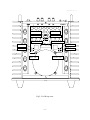
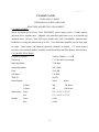
CA-200 ISSUE 3 DEC. ‘97
CLASSÉ AUDIO
CA-200
POWER AMPLIFIER
CA-200
OWNER'S MANUAL
CA-200 ISSUE 3 DEC. ‘97
CLASSÉ DESIGN PHILOSOPHY
1. REPEATED LISTENING DESIGN SESSIONS:
Fine tuning of sound by exchanging and mixing of parts (transistors, capacitors, wiring, PCB
boards etc.), and adjusting many specific operating voltages within proper engineering ranges,
producing an overall sonic recipe giving the most natural harmonic realism of music typical of
instruments in a live performance.
2. UPGRADABLE SINGLE CIRCUIT DESIGNS:
All Classé products (all preamps and all amps) share exactly the same circuit (excluding moving
coil and moving magnet phono circuits). This means all amplifiers and all high level circuits of
the preamps are the same. The same circuit is tailored to different power levels etc. Differences
between less expensive models and more expensive models are parts quality and compliment,
power supply extravagance and the amount of filtering etc., as well as features and packaging.
This means that for years Classé has been constantly fine tuning and upgrading this circuit and
its application, thus reaching a very high level of understanding and musical achievement which
benefits all models - least expensive, most expensive, preamps and amplifiers alike.
3. EXTREME LONG LIFE IN REAL WORLD CONDITIONS:
Choosing the best attainable quality parts and materials combined with the advantages of the two
above-mentioned areas provides Classé owners with years of proven trouble free reliability and
musical enjoyment.
-2-
CA-200 ISSUE 3 DEC. ‘97
CA-200
OWNER'S MANUAL
TABLE OF CONTENTS
UNPACKING & SET-UP............................................................... 4
GENERAL CONNECTIONS.......................................................... 5
CONNECTIONS FOR REGULAR OR BALANCED INPUTS ... 8
PROTECTION CIRCUIT................................................................ 10
CA-200 BACK VIEW....................................................................... 11
CA-200TOPVIEW..............................................................................12
SPECIFICATIONS........................................................................... 14
-3-
CA-200 ISSUE 3 DEC. ‘97
UNPACKING & SET-UP
Your CLASSÉ CA-200 power amplifier is packed in high density, semi-rigid foam placed in
a special cardboard box. To remove the unit, open and spread all the top flaps of the box and by its
sides, lift out the entire unit and put it on a large flat surface. Take it out of the plastic bag and
inspect the unit for any concealed damage. Apart from this owner's manual, please ensure the
following has also been included:
1) Detachable A.C. linecord
2) Allen key for top plate
3) Nut driver for output connectors
Please report any damage or missing parts to your dealer immediately.
Place the CA-200 at or near its final set-up position, allowing 8 inches at the rear for
tightening the speaker output connectors. For optimum sonic performance, we recommend the
optional CLASSÉ REFERENCE A.C. LINECORD. Consult your dealer regarding this accessory.
The power transformer in the CA-200 is located at the front-center of the unit. Ideally, a few
feet should separate this area from components which potentially could pick up hum. These include
preamplifiers, turntables, and interconnect cables. In terms of providing adequate airspace for
cooling, a good rule of thumb is to allow 6 inches above and 3 inches on each side of the unit.
Check the Serial Number sticker on the back of the unit for the correct operating voltage.
The CA-200 has one external AC fuse, the rating of which should be as follows:
LINE VOLTAGE
100 or 120 V.A.C.
FUSE RATING
10 AMP SLOW BLOW
125 or 250 volts
220 or 240 V.A.C.
8 AMP SLOW BLOW
250 volts
-4
CA-200 ISSUE 3 DEC. ‘97
GENERAL CONNECTIONS
A.C. LINE
Insert the linecord into the A.C. receptacle on the rear of the unit.
CAUTION: SAFETY INSTRUCTIONS
DISCONNECT AC LINE CABLE WHILE MAKING ALL CONNECTIONS. "FLOATING THE
GROUND” OR DEFEATING THE GROUND ON A 3-PRONG LINECORD MAY CREATE
A SHOCK HAZARD. CONNECT ALL INTERCONNECT CABLES BETWEEN THE
ELECTRONICS BEFORE CONNECTING THE A.C. LINECORDS TO THE WALL
OUTLETS. THIS WILL REDUCE THE POTENTIAL SHOCK HAZARD.
STEREO
Input and output connectors are clearly marked on the back of the amplifier. Left/Right
connections are oriented from the front of the unit. Stereo output connections are marked above the
connectors. Switch stereo/mono switch to STEREO position. (The CA-200 is preset at the factory
for STEREO.)
Use only high quality interconnect and loudspeaker cables, and make all connections tight. If
the RCA input plugs are loose, remove them and pinch down the ground leaves slightly with pliers.
Observe correct phasing of the loudspeaker connections, and tighten. DO NOT OVERTIGHTEN
the output connectors.
-5
CA-200 ISSUE 3 DEC. ‘97
MONO
Please read through the previous Stereo section for general notes on securing good
connections, and safety tips. If the unit has been previously used in stereo, make sure it is OFF, and
remove all connections, including the AC line cable. Make sure the STEREO/MONO switch is
switched to the MONO position. NOTE: The Stereo-Mono switch will not operate if the amplifier is
turned on, you will NOT be able to change from one mode to the other, as the mode is “locked”
while the amplifier is on.
The MONO "Input" is the "left channel input", as marked. The unused right channel input is
automatically disconnected. Correct output phase MONO connections are marked below the
connectors.
Repeat the above MONO settings and connections on the second CA-200 to be used for the
other channel.
Please remember that the negative output connection of a bridged amplifier is NOT a
ground. Do not use a "common ground” switch-box set-up. Do not use with electronic crossovers
which have a common ground. Connecting two bridged amplifiers to a common ground device of
any sort will cause the amplifiers to fail.
REMOTE CONTROL: (OPTIONAL)
With a simple connection from a ClassJ “Remote Interface Box” to the remote jack at the
back of the amplifier, (see Figure 1) the CA-200 can be turned ON or OFF from a distance (or from
another room). The “Remote Interface Box” repeats the information sent to the LED on the front of
the amplifier, allowing remote mounting of the amplifier.
-6
CA-200 ISSUE 3 DEC. ‘97
IR OUT and IN:
The CA-200 may also be turned on and off using our SSP-50 Surround Sound Processor,
utilising the IR OUT and IN jacks. To turn on your CA-200 with the SSP-50, Disconnect you
CA200 from the AC line completely, open the top cover and locate the 4 internal jumpers inside the
CA-200 (see fig. 2, page ) alongside the mosfet fuses. When facing the amplifier from the front,
remove the jumper located completely to the right and save this jumper. Re-install the top cover.
Install a mini jack into IR IN at the back of the CA-200 and plug the other end of the mini jack into
the 5VDC mini jack at the back of your SSP-50. When the Standby button of the SSP-50 is pressed,
it will now activate the turn on turn off circuitry of your CA-200. Several amplifiers may be turned
on automatically in sequence or all at once, depending upon the configuration of the jumper settings
in the amplifier. You will find these jumpers located inside the unit (see fig.2 page) alongside the
mosfet fuses. The table below tells you which jumper should be inserted or removed to obtain the
correct sequence on which you will want your amplifier to turn on.
J3
J2
J1
J0
ADRESS
RC Button
Auto ON
X
X
X
X
0
Amp 1
No
X
X
X
out
1
Amp 2
No
X
X
out
X
2
Amp 3
No
X
X
out out
3
Amp 4
No
X
out
X
X
4
Amp 5
No
X
out
X
out
5
Amp 6
No
X
out
out
X
0
Amp1
No
X
out
out out
0
Amp 1
Yes
-7
CA-200 ISSUE 3 DEC. ‘97
SEQUENTIAL TURN ON
Your CA-200 is factory set as being the 1st amp (AMP 1) to be turned on in sequence. To reprogram your unit so that it would be the 2nd , 3rd, 4th, 5th or 6th amp to be turned on in sequence you
have to follow this procedure. Push and hold the power button, when the LED becomes solid green,
depress the button and then press again. The number of times you will press again will determine
when the amplifier will turn on in the sequence. See example on the next page.
EX: Push and hold power button until solid green, when power LED is solid green, depress button
and then push 2 times. Then your amplifier will be the 2nd one to turn on in the sequence.
-8
CA-200 ISSUE 3 DEC. ‘97
CONNECTIONS FOR REGULAR OR BALANCED INPUTS:
The CLASSÉ CA-200 power amplifier is equipped with both regular and balanced inputs.
Either one may be used
SEPARATELY, BUT NOT SIMULTANEOUSLY.
The balanced inputs must be
connected to a preamplifier which has balanced main outputs. Balanced interconnects with
"XLR"
connectors are also required. Regardless of the amplifier inputs used, stereo or mono operation is
possible on the CA-200.
REGULAR INPUTS
Switch the REGULAR/BALANCED switch to the position marked "REGULAR". (The amplifier is
factory set for “REGULAR”.) NOTE: The
REGULAR/ BALANCED
switch will not operate if the
amplifier is turned on; you will NOT be able to change from one mode to the other, as the mode is
“locked” while the amplifier is on. Connect the regular interconnects to the RCA input jacks on the
rear panels of the CA-200. The balanced connectors are automatically disabled.
BALANCED INPUTS
Switch the
REGULAR/BALANCED
switch to the position marked
"BALANCED".
A balanced
preamplifier and balanced interconnects are also required. NOTE: The REGULAR/ BALANCED switch
will not operate if the amplifier is turned on; you will NOT be able to change from one mode to the
other, as the mode is “locked” while the amplifier is on. For use with balanced preamplifiers other
than Classé, the wiring of the 3-pin XLR connectors must be matched to that of the CLASSÉ CA-200
which are wired as follows:
PIN 1: GROUND
PIN 2: POSITIVE (NON-INVERTED) SIGNAL, “HOT”
PIN 3: NEGATIVE (INVERTED) SIGNAL
-9
CA-200 ISSUE 3 DEC. ‘97
BALANCED INPUTS (CONTINUED)
All Classé preamplifiers and amplifiers are configured as above. Some preamplifiers from other
manufacturers have PIN-3 set as the positive or “HOT” side. If this is true of your preamplifier, and
you wish to maintain absolute phase throughout your system, the interconnects must have the wire
which is connected to PIN-3 at the preamplifier output end switched to PIN-2 at the amplifier input
end and the wire which is connected to PIN-2 at the preamplifier output switched to PIN-3 at the
amplifier input end.
Having confirmed the correct connections, plug the
XLR
connectors of the balanced
interconnects into the locking XLR connectors on the rear panel of the CA-200. Push the connectors
in until the locking mechanism clicks. (To remove the connectors, press the tab above the connector
while pulling gently on the connector body.)
MONO OPERATION
As stated above, either the regular or balanced inputs can be used in stereo or mono.
Connect a single interconnect, either regular or balanced, to the left channel input of each amplifier.
See the "Mono" section above for complete details. NOTE: Neither the Stereo-Mono switch nor the
REGULAR/ BALANCED
switch will operate while the amplifier is turned on. You will NOT be able to
change from one mode to the other, as these modes are “locked” while the amplifier is on.
-10
CA-200 ISSUE 3 DEC. ‘97
PROTECTION CIRCUIT
The Classé CA-200 is equipped with rail fuses to protect the output drivers (GDB6, 6 amps
fast blow. fig.2, page 11) and mosfet fuses (2AG 1/2 PT, 1/2 amp fast blow) to protect the mosfets,
which are used as pre-drivers for the output stage of the amplifier. In the event that a short circuit or
other problems would occur at the output of the amplifier, one or more of these fuses may blow in an
attempt to protect the amplifier. In addition to the fuses, the unit has a circuit for the detection of
unusual distortion characteristics and/or DC content in the incoming audio signal. There is also an
AC line fuse protecting the unit. It is located at the back of the unit immediately above the AC
receptacle (see fig.1, page 10).
If the protection circuit of the unit is triggered or any of the fuses has blown, the FRONT
PANEL POWER LED will go to BLINKING GREEN, indicating a “fault” condition.
IF THE PROTECTION CIRCUIT HAS BEEN TRIGGERED, TURN THE CA-200 OFF.
.After the situation which has triggered the protection circuit has been clearly identified and
corrected, attempt to re-start the unit. IF THE UNIT STILL GOES INTO PROTECTION MODE,
OR IF IT APPEARS THAT PROTECTION FUSES DID BLOW, CONTACT YOUR LOCAL
DEALER. DO NOT TRY TO CHANGE A BLOWN FUSE. REPLACING A FUSE WITHOUT
CHECKING FOR COMPONENT FAILURE COULD RESULT IN FURTHER, SERIOUS
DAMAGE TO VITAL COMPONENTS IN YOUR AMPLIFIER. CONTACT YOUR LOCAL
DEALER or Customer Service at the Classé Audio, Inc ---(514) 636-6384.
-11
CA-200 ISSUE 3 DEC. ‘97
Fig 1: CA-200 back view
-12
CA-200 ISSUE 3 DEC. ‘97
-Mosfet fuse
-Mofet fuse
+Mofet fuse
+Mofet fuse
aux AC fuse
aux AC jumper
-Rail fuse
-Rail fuse
+Rail fuse
+Rail fuse
RIGHT CH.
LEFT CH.
Fig 2: CA-200 top view
-13
CA-200 ISSUE 3 DEC. ‘97
CLASSÉ AUDIO
5070 François Cusson
Lachine, Quebec
Canada H8T 1B3
Telephone: 514 636 63 84
Fax: 514 636 14 28
-14
CA-200 ISSUE 3 DEC. ‘97
CLASSE CA-200
ULTRA HIGH CURRENT
STEREO/MONO POWER AMPLIFIER
FEATURES AND SPECIFICATIONS SHEET
CA-200 FEATURES:
Newly developed special Classé "UHC TRANSFER" power supply section. Current capacity
increased above standard units. Magnetic flux controlled transformer cover in a brushed and
anodized finish. All new Classé PCB circuit boards with "UHC TRANSFER" characteristics.
Reduction of wiring and connections up to 70%. True differential amplifier circuits from input
to output. Both regular and balanced operation externally switchable. 1/2" thick brushed
faceplate with contoured handles. Available in both Satin Black and Soft Shadow Silver finishes.
CA-200 SPECIFICATIONS:
Frequency response:
20 Hz to 20 KHz +/- 0.1 dB
Sensitivity:
1.3 Volts in for rated output
Input Impedance:
75 K ohms
Output Impedance:
0.017 Ohm
Gain:
29.02 dB
S/N Ratio:
135 dBR
THD+N:
0.004%
Rated Output:
Stereo
Mono
8 Ohms:
200
700 Watts
4 Ohms:
400
1200 Watts
Dimensions: Gross:
Weight:
23" x 19 1/2" x 10 1/2"
Net:
19" x 18 1/2" x 7 3/4"
Gross:
69 lbs.
Net:
60 lbs.
-15
CA-200 ISSUE 3 DEC. ‘97
Notice to all Classé Product owners:
Thank you
component.
for
your
purchase
of
a
Classé
Audio
All of us at Classé have taken extreme care to ensure
that your purchase will become a prized investment. We
are proud to inform you that all Classé Audio
components have been officially approved for the
European Community CE mark.
This means that your Classé product has been subjected
to the most rigorous manufacturing and safety tests in
the world, and have proven to meet or exceed all
European Community CE requirements for unit to unit
consistency and consumer safety.
All of us at Classé
musical enjoyment.
Audio
wish
you
many
years
of
As of July 18, 1996, Classé Audio has been granted
Certificate No: C401CLA1.MGS, which indicates CE
approval for all models of the Classé Audio product line.
-16