1
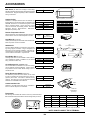
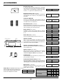
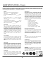
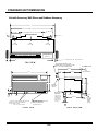
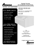
Amana Package Terminal
M
o
B
d
Air Conditioners & Heat Pumps
Amana Value Difference
Amana
Quality
Difference:
Built-in
“Standard”
features:
• High
efficiency
operation
• Remote
temperature
• Compressor
restart
• Ultra
quiet operation
sensing
delay
• Enhanced
• Reliability
anddehumidification
Durability
• Filtered
• Full
factory ventilation
testing
• Remote
control
• Five
year warranty
Amana Quality Difference:
•
•
•
•
•
High efficiency operation
Quiet Operation
Reliability and Durability
Full 100% factory testing
Five year warranty
air intake
functions
• Random unit restart circuit
• Room freeze protection
• Front desk control
Amana Value Difference
Built-in “Standard” features:
Industry Leading Warranty
Industry Leading Performance
7,000 - 14,200 BTUH Cooling
6,200 - 13,300 BTUH Heating
Electric heat up to 5.0 kW
Hydronic heat up to 23,700 BTUH
Up to 11.6 EER
Up to 3.3 COP
• Remote temperature sensing
One Year Full
•
Five Year
Fullfunctions
Sealed
• Remote
control
System
Limited Five Year Functional Parts
• Compressor restart delay
• Increased dehumidification capacity
• Filtered ventilation air intake
• Random restart circuit
• Front desk control
®
Don’t settle for less than the
Amana “Standard” Advantage !!
e
l
THE AMANA “STANDARD” ADVANTAGE
Amana has designed the Packaged Terminal Air Conditioner for customer comfort and owner peace of mind. No other unit
in the industry offers so many “extras” already built in as “STANDARD” on every unit. With all the features and benefits our
units have to offer, you no longer need to settle for anything less than the Amana “Standard” Advantage!!
Standard Features
Advantages and Benefits
Enjoy one of the most comprehensive warranties in the industry. Full 1-year warranty on unit parts
Five-Year Warranty and labor; full 5-year warranty on the entire sealed system components; limited parts-only warranty
on functional components. See back of this brochure for details.
Energy
Efficiencies
Our units' high efficiencies can qualify you for many of the rebates offered by electrical
power companies. EER’s up to 11.6 and heat pump COP’s up to 3.3 keep energy consumption
to a minimum.
Freeze
Protection
No more worries about bursting water pipes or broken fixtures caused by freezing temperatures.
W hen the unit senses temperatures of 40 degrees Fahrenheit or below, the unit activates the
fan motor, and either the electric resistance heater or the hydronic heater.
7" Unit Front
Enhance valuable room space -- the unit front has a sleek 7" depth, one of the shallowest
silhouettes in the industry today. In addition, to inhibit guest-tampering, the front can be secured
to the chassis with hidden screws.
Versatile Style
Our unit's new stylish design and neutral color make it compatible with virtually any room décor
or architectural design. The unit becomes less noticeable as it blends into the room's color scheme.
Easy To Use
Controls
No complex controls to confuse your guests and create phone calls for your manager. Controls
are easy to read, understand, and activate.
Remote
Thermostat
Control
Each unit is built to be operated from a remote-mounted thermostat, if desired. Even if you start
without a remote, you can take advantage of a built-in low voltage power source which
accommodates a variety of thermostat choices --manual, auto change-over, or
programmable -- at a later date.
Increased
Dehumidification
Capacity
Maintain lower humidity levels in rooms while cooling them without the need for expensive
add-on’s. As a result, guests feel more comfortable at higher temperatures, thus reducing
cooling costs, and the life of your furniture, wall coverings, and fixtures is extended which means
less replacement costs.
Quiet Operation
The unit's state of the art design and construction provide a quiet environment allowing guests to
enjoy peaceful, sleep-filled nights. Operating sound levels are further dampened when unit is in
"low fan" mode of operation.
Filtered Ventilation Guest's rooms stay cleaner, longer. The hidden ventilation air intake filters outside air to reduce
dust and other airborne material.
Air
Obtain greater savings by centrally controlling units and eliminate wasted energy generated by
Front Desk Control cooling and heating unoccupied rooms. Each unit has low voltage interface capability with a
field supplied front desk ON/OFF switch.
Easy to Service
Remote
Temperature
Sensing
The main components are easily serviced; the unit is easy to diagnose or troubleshoot to
spot potential problems.
Guests enjoy ultimate comfort with consistent climate control. Attach an optional, inexpensive
remote thermistor temperature sensing device, and temperatures are held more closely to the
chosen room setting.
The Amana condensate dispersion system removes condensate from indoor cooling operation by
Condensate
throwing water directly on to the outdoor coil for rapid evaporation and increased cooling efficiencies. The
Dispersion System slinger ring on the fan blade draws water up and into fan blade. This water is then atomized and evaporated
into the atmosphere through the condenser.
B-2
THE AMANA “STANDARD” ADVANTAGE
Standard Features
Automatic
Emergency Heat
Advantages and Benefits
No more "my unit is not heating" complaints during the middle of the night. Heat pump units will automatically
switch over to electric resistance heat if for any reason the heat pump compressor system fails or if the
heating load is greater than the unit capacity.
Fan Mode
Switch
Take advantage of each unit's dual options: select continuous fan operation or cycle the fan ON
and OFF with the thermostat.
Zero Floor
Clearance
Unit can be installed flush to the finished floor, if desired. (Some accessories do not have
zero clearance).
Temperature
Limited
Random Restart
Compressor
Restart Delay
Save energy and money by avoiding the extreme settings that can occur with guest operation. The
unit-mounted mechanical temperature limited allows guests to adjust in-room temperature
settings while maintaining a pre-programmed range set by you.
Avoid troublesome power surges that can damage electrical circuits. Each unit has a random restart circuit to
prevent all units from restarting at one time after power disruption. Random restart occurs in 2-4 minutes.
Extended compressor-life. The unit automatically delays any restart attempt by three minutes to
allow the refrigerant pressures time to equalize.
Accessory
Wall Sleeve
No more worries about changing out non-standard sleeves that do not accommodate the bulk
of what the industry has to offer. Amana's wall sleeve is an industry standard size of 13-3/4"
13-3/4" x 42" x16-1/16" deep x 42" wide x 16-1/16" high. (Please Note: Wall Sleeve must be ordered separately.)
Power Cord Plugs
Easy Filter Access
Step 1: Open the intake grille
250V Rating Power Cord Plugs
NEMA 6 Configuration
Maintaining the unit’s efficiency while saving time and
money is as easy as 1-2-3.
The filter is easily accessed
for cleaning or replacement
without removing the unit front.
15 amp
30 amp
20 amp
W
W
G
G
277V Rating Power Cord Plugs
NEMA 7 Configuration
20 amp
30 amp
Power Recptacle Configuration (Field Supplied)
G
NEMA6-15R; 250V receptacle, used on
230/208V units
G
NEMA6-20R; 250V receptacle, used on
230/208V units
G
NEMA7-20R; 277V receptacle, used on
265V units
W
G
Step 2: Pull open the intake grille
Step 3: Press down lightly on the thumb tab
at the top of the filter and remove the filter.
B-3
NEMA6-30R; 250V receptacle, used on
230/208V units
G
NEMA7-30R; 277V receptacle, used on
265V units
All units come with
factory installed
power cord.
SPECIFICATIONS - COOLING/ELECTRIC HEAT
PTC Models
Cooling Performance
Model (Basic) (NOTES 1, 7 & 9)
PTC073A**AB
PTC074A**AB
PTC093A**AB
PTC094A**AB
PTC123A**AB
PTC124A**AB
PTC153A**AB
230/208
265
230/208
265
230/208
265
230/208
265
7,100 / 7,000
7,100
9,100/8,900
9,100
12,000 / 11,900
12,000
14,200 / 14,000
14,200
Voltage (NOTES 1 & 3)
Capacity (BTUH)
PTC154A**AB
Amps
2.8/3.0
2.3
3.7/3.8
3.0
4.6/5.0
4.3
6.3 / 6.9
5.9
Watts
610 / 600
610
805 / 785
805
1,120 / 1,110
1,130
1545 /1520
1,525
EER
11.6
11.6
11.3
11.3
10.7
10.7
9.2
9.3
Unit without Electric Heater
Min.Circuit Ampacity (NOTES 2 & 4)
4.0
3.6
5.1
4.4
6.4
5.7
8.4
7.4
245 / 240
245
245 / 240
245
325 / 315
325
325/315
325
220 / 205
220
220 / 205
220
250 / 229
250
250/220
250
265 / 260
265
265 / 260
265
345 / 335
345
345/335
345
230 / 215
230
230 / 215
230
265 / 235
265
265/235
265
Ventilated Air, CFM (Fan Only)*
65*
65*
65*
65*
70*
70*
70*
70*
Ventilated Air, CFM (Compressor & Fan)*
65*
65*
65*
65*
70*
70*
70*
70*
Dehumidification (Pints/Hr.)
1.6
1.6
2.6
2.6
3.5
3.5
4.4
4.4
Net Weight (approximate Lbs.)
90
90
95
95
105
105
110
110
Shipping Weight (approximate lbs.)
105
105
110
110
120
120
125
125
CFM (Cool, Wet Coil) High
Low
CFM (Dry Coil)
High
Low
* Approximately 95 CFM with optional power vent kit. Actual vent CFM performance will vary due to application and installation conditions.
Electric Heater Performance (PTC and PTH Models)
(Primary Heating for PTC models; Auxiliary Heating for PTH models)
NOMINAL HEATING
ELECTRIC
TOTAL
TOTAL
MIN. CIRCUIT
OVERCURRENT
HEATER
NO. OF
BTUH
BTUH
BTUH
WATTS
AMPS
AMPACITY
PROTECTION
POWER
SIZE (kW)
STAGES
AT 230V
AT 208V
AT 265V
(NOTE 6)
(NOTE 8)
(NOTE 2)
(NOTE 4)
CORD
230/208V
2.5/2.0
1
8,500
6,800
--
2,650/2,140
11.5/10.2
14.2
15
6 - 15 P
230/208V
3.5/2.9
1
12,000
9,900
--
3,650/3,040
15.8/14.5
19.6
20
6 - 20 P
230/208V
5.0/4.1
**
17,100
14,000
--
5,150/4,240
22.3/20.3
27.7
30
6 - 30 P
265V
2.5
1
--
--
8,500
2,650
10.0
12.4
15
7 - 20 P
265V
3.7
1
--
--
12,600
3,850
14.6
18.1
20
7 - 20 P
265V
5.0
**
--
--
17,100
5,150
19.5
24.2
25
7 - 30 P
VOLTAGE
**PTC/H07*A50*B, PTC/H09*A50*B, and PTC/H12*A50*B are 2-stage; PTC/H15*A50*B is 1-stage.
Hydronic Heat Models
C
PT
07
3
A
35
A
B
Hydronic Models / Hot Water & Steam Heating
These special models are shipped without a chassis
front, without electric heat, and have an additional relay and 40VA transformer for water or steam valve
operation. Also available in Hydronic with Powered
Vent and Hydronic with Powered Door. See Model
Identification (right) for Special Feature Codes for these
models. See 7b for hydronic accessories.
Hydronic with Manual Door
Model Number
Voltage
Capacity
Cooling
Capacity
EER
PTC093A00HB
230/208
9,100 / 8,900
11.3
PTC123A00HB
230/208
12,000 / 11,900
10.7
PTC153A00HB
230/208
14,200/14,000
9.2
PTC094A00HB
265
9,100
11.3
PTC124A00HB
265
12,200
10.7
PTC154A00HB
265
14,200
9.3
ENGINEERING DESIGN LEVEL
(A - Z)
SPECIAL FEATURE CODE
A = Standard Model
B = Power Vent
C = Sea Coast Model
D = Cond. Disposal Pump
F = Hydronic w/Power Vent & Door
G = Hydronic w/ Power Door
H = Hydronic w/Manual Door
J = Power Door
K = Cond. Pump & Power Vent
L = Cond. Pump & Power Door
PACKAGE
TERMINAL
MODEL TYPE
C = Cooler
H = Heat Pump
NOMINAL
COOLING CAPACITY (Btuh)
07 = 7,000 Btuh
09 = 9,000 Btuh
12 = 12,000 Btuh
15 = 15,000 Btuh
VOLTAGE
3 = 230/208v 60 Hz 1 PH
4 = 265v 60Hz 1 PH
5 = 240/220v 50Hz 1 PH
HEATER SIZE
(see note 7, pg. 5)
00 = 0.0 KW
(PTC Models Only)
15 = 1.5 KW
25 = 2.5 KW
35 = 3.5 KW (230 volt/208 volt)
3.7 KW (265 volt)
50 = 5.0 KW
MAJOR DESIGN SERIES
B-4
SPECIFICATIONS - COOLING/HEAT PUMP & ELECTRIC HEAT
PTH Models - Heat Pumps
Heat Pump Cooling Performance
Model (Basic) (NOTES 1, 7 & 9)
Voltage (NOTES 1 & 3)
Capacity (BTUH)
PTH073A**AB
PTH074A**AB
PTH093A**AB
PTH094A**AB
PTH123A**AB
PTH124A**AB
PTH153A**AB
230/208
265
230/208
265
230/208
265
230/208
PTH154A**AB
265
7,100 / 7000
7,100
9,000/8,800
9,000
12,000 / 11,800
12,000
14,000/13,800
14,000
Amps
2.8/3.0
2.3
3.5/3.8
3.0
4.6/5.0
4.3
6.3/6.9
5.9
Watts
615/610
615
805 / 785
805
1,120 / 1,110
1,120
1505 / 1485
1,505
EER
11.5
11.5
11.2
11.2
10.7
10.7
9.3
9.3
Units without Electric Heater
Min.Circuit Ampacity (NOTES 2 & 4)
4.0
3.6
5.1
4.4
6.4
5.7
8.4
7.4
245 / 240
245
245 / 240
245
325 / 315
325
325/315
325
220 / 205
220
220 / 205
220
250 / 229
250
250/220
250
265 / 260
265
265 / 260
265
345 / 335
345
345/335
345
230 / 215
230
230 / 215
230
265 / 235
265
265/235
265
Ventilated Air, CFM (Fan Only)*
65*
65*
65*
65*
70*
70*
70*
70*
Ventilated Air, CFM (Compressor & Fan)*
65*
65*
65*
65*
70*
70*
70*
70*
Dehumidification (Pints/Hr.)
1.6
1.6
2.6
2.6
3.5
3.5
4.4
4.4
Net Weight (approximate lbs.)
95
95
100
100
110
110
115
115
Shipping Weight (approximate lbs.)
110
110
115
115
125
125
130
130
CFM (Cool, Wet Coil)
High
Low
CFM (Dry Coil)
High
Low
* Approximately 95 CFM with optional power vent kit. Actual vent CFM performance will vary due to application and installation conditions.
Heating Performance - Reverse Cycle
Heating Capacity
Reverse Cycle (NOTE 1)
BTUH (NOTE 5)
Amps
Watts
COP (NOTE 5)
CFM (Dry)
Heating, BTUH
(Note 5)
Outdoor Ambient
Rating Point
Watts
Outdoor Ambient
°F
62
57
52
47
(COP)
42
37
32
62
57
52
47
42
37
32
27
(See facing page for Auxillary Electric Heater Performance and Power Cord Configuration)
PTH073A**AB
PTH074A**AB
PTH093A**AB
PTH094A**AB
PTH123A**AB
PTH124A**AB
PTH153A**AB
PTH154A**AB
6,400/6,200
2.6/3.0
570/550
3.3
235/230
6,400
2.2
570
3.3
235
8,100/8,000
3.2/3.6
740/730
3.2
235/230
8,100
2.6
740
3.2
230
10,800/10,600
4.5/5.1
1,020/1,000
3.1
310/290
10,800
3.9
1,020
3.1
310
13,300/13,200
5.7/6.3
1,390/1,380
2.8
345/335
13,300
5.4
1,390
2.8
345
8,400/8,200
7,800/7,600
7,100/6,900
6,400/6,200
3.3/3.3
5,700/5,500
5,100/4,900
4,500/4,300
645/625
630/610
595/575
570/550
540/520
515/505
495/485
460/450
8,400
7,800
7,100
6,400
3.3
5,700
5,100
4,500
645
630
595
570
540
515
495
460
10,300/10,200
9,700/9,600
9,000/8,900
8,100/8,000
3.2/3.2
7,300/7,200
6,500/6,400
5,700/5,600
835/825
805/795
780/770
740/730
710/700
675/665
630/620
590/580
10,300
9,700
9,000
8,100
3.2
7,300
6,500
5,700
835
805
780
740
710
675
630
590
13,200/13,000
12,400/12,200
11,600/11,400
10,800/10,600
3.1/3.1
10,000/9,800
9,200/9,000
8,400/8,200
1,151/1,095
1085/1065
1,055/1,035
1,020/1,000
985/965
945/925
915/895
885/865
13,200
12,400
11,600
10,800
3.1
10,000
9,200
8,400
1,115
1,085
1,055
1,020
985
945
915
885
16,400/16,300
15,400/15,300
14,300/14,200
13,300/13,200
2.8/2.8
12,300/12,200
11,300/11,200
10,200/10,100
1,540/1,530
1,500/1,490
1,450/1,440
1,390/1,380
1,335/1,325
1,250/1,240
1,170/1,160
1,110/1,090
16,400
15,400
14,300
13,300
2.8
12,300
11,300
10,200
1,540
1,500
1,450
1,390
1,335
1,250
1,170
1,100
NOTES:
1. All 265v models must use Amana’s subbase (PTSB4**C) or Amana’s hard wire kit (PTPWHWK4)
2. Minimum branch circuit ampacity ratings conform to the National Electric Code. However, local codes
should apply.
3. Minimum voltage on 230/208 volt models is 197 volts; maximum is 253 volts. Minimum voltage on 265 volt
models is 238.5 volts; maximum is 291.5 volts.
4. Overcurrent protection for all units without electric heaters is 15 amps. Overcurrent protection on 265
volt models must be cartridge-style time delay fuses (included and factory installed on Amana chassis).
5. Heating capacity and efficiency is based on unit operation without condensate pump. Unit automatically
switches to electric heat at 25°F (nominal) outdoor coil temperature.
6. Total watts for 15,000 Btuh models; subtract 30 watts for PT12*A**AB and 70 watts for PT07/09*A**AB.
7. Please specify 2-digit heater kW size to complete model number.
8. Total amps for 12,000 and 15,000 Btuh models; subtract 0.2 amps for PT07/09*A*AB.
9. Refrigerant used in all systems is R-22.
B-5
EER -
COP -
Energy Efficiency Ratio per American
Refrigeration Institute (ARI) Test
Procedures and Canadian Standards
Association (CSA) EEV Test
Procedures.
Coefficient of Performance per ARI
Test Procedures
ACCESSORIES
Wall Sleeve (42” wide x 16-1/16 high x 13-3/4” deep)
WS900B
Wall Sleeve
16-1/16"
(408 mm)
Standard insulated wall sleeve fits all Amana Packaged
Terminal Units. Shipped separately to allow installation
during construction.
42"
(1066.8mm)
Outdoor Grilles
Available in stamped aluminum and an attractive extruded aluminum architectural grille for application with
WS900B wall sleeve. The architectural grille is available in anodized natural, 3 stock colors and custom
colors to blend with the building exterior. CB=Clear,
DB=Dark Bronze, ZB=Driftwood, WB=White,
SB=Special (Custom) Color
"
/4 )
-3 m
13 9.3m
4
(3
Standard Outdoor Grille
SGK01B
Single Pack
SGK10B
Ten Pack
SGK
Architectural Grille
AGK01*B
Single Pack
AGK
Remote Temperature Sensor
Allows inexpensive, low voltage temperature sensing on
internal wall for more accurate temperature control.
RTS01
Remote
Temperature Sensor
PTPWHWK4
Hard Wire Kit
Hard Wire Kit (not shown)
Used to permanently wire to chassis when standard subbase and power cord are not utilized.
Optional
Fuse Holder
Location
Subbase Kit
The fully skirted subbase conceals wiring while providing strong support, if needed. Plug-in receptacle and
field wiring access speeds installation. Electrical accessories such as fuse holders, circuit breakers and disconnect switches meet N.E.C. requirements.
PTSB320C
230/208V 15/20A
PTSB330C
230/208V 30A
PTSB420C
265V 15/20A
PTSB430C
265V 25A
Optional
Power Switch and Circuit Breaker
Location
Power Receptacle
Skirting
Fuse Holder Kit (not shown)
Skirting
Leveling Legs
Cartridge style fuses can be installed in fuse holder for
use in subbase or chassis. Available in 15, 20 and 30
amp. (Included on 265v unit).
Subbase Box Assembly
FHK315C
230/208V 15A
FHK320C
230/208V 20A
FHK330C
230/208V 30A
CBK3**C
Circuit Breaker Kit
PSHW03A
230/208V
PSHW04A
265V
DK9001
Condensate
Drain Kit
Circuit Breaker Kit (230/208v only)
The circuit breaker kit, available in 15, 20, 25 or 30 amp,
can be used with Amana's subbases. It gives overcurrent protection and its location allows turning unit on or
off without tools.
Power Disconnect Switch (not shown)
The PSHW**A power disconnect switch can be used
for 265 or 230/208 volt physical disconnect where required by local codes. The switch is rated at 30 amp
capacity. The switch is for use with Amana's standard
subbases or PTPWHWK4 Hard Wire Kit.
Condensate Drain Kit
Attaches to the wall sleeve base pan for controlled internal or external disposal of condensate
.
Gasket
Cover
Plate
1/2" OD
Drain Fitting
(12.7mm)
Thermostats
The following thermostats offer remote control. Any thermostat other
than those listed must be submitted to Amana for approval prior to use.
60
®
AIR
CONDITIONING
60
90
70
Cool Stages
Programmable
2
Shape
1
Yes
Rectangle
D9945801
2
1
No
Rectangle
D6853511
1
1
No
Rectangle
C5200609
1
1
No
Round
20189101*
2
1
No (Auto Changeover)
Rectangle
80
90
70
Heat Stages
D9807605
80
®
* Note: Thermostats listed above are manual changeover except for 20189101
NOTE: DO NOT CONNECT THE X1 TERMINAL.
B-6
ACCESSORIES
Security Key Locks
In conjunction with the tamper-resistant front, the installation of Amana’s security key locks prevents tampering of the
controls used to set temperature, heating and cooling
functions. U.L. approved for institutional use only.
KL03
Security Key Lock
Remote Escutcheon Kit (not shown)
Optional kit for use with units controlled via a wall thermostat. Replaces knob controls for units operated by wall
thermostat.
REK10A
Remote Escutcheon
Kit (10/pack)
Condenser Baffle Kit
For use on non-baffled grilles. These deflectors direct the
air in toward the center and away from the inlet to prevent
recirculation of the hot condenser air.
Duct Extension Kit (not shown)
Extends air distribution to an adjoining room. Consists of a
main duct for the room of origin and an extension duct to
reach the adjoining room and terminal duct.
Power Vent Kit (not shown)
Installation of Power Vent increases CFM up to approximately 95. Vent door will automatically close when unit fan
is off.
Power Door Kit (not shown)
Vent door will automatically open when unit fan is on.
Hot Water Inlet / Outlet Connections
Steam Inlet / Outlet Connection
Hydronic Heat Kit
Steam/Water
Coil Position
Hot Water Inlet / Outlet Connections
Steam Inlet / Outlet Connections
16-3/4"
Add-on kits fit all units allowing the addition of hydronic
water or hydronic steam heat to cooling and heating units.
The kits feature left- or right-hand piping. Unit retains complete service access with a kit installed.
8-1/4"
Condenser
Baffle Kit
DGK1
MDK02
Main Duct
EDK02
Extension Duct
TDK02
Terminal Duct
PVK3A
230/208V
PVK4A
265V
PDK3A
230/208V
PDK4A
265V
HWK03
Hydronic Water Kit
HVK03
Hydronic Steam Kit
HTK3
230/208V
HTK4
265V
20-3/16"
2-1/8"
53"
Hydronic Air
Inlet
FRONT VIEW
(unit wi/Hronic Kit installed)
Hydronic Transformer Relay Kit (not shown)
Add-on kit that allows field conversion of a standard PTC
unit to a Hydronic unit.
Hydronic Valves (not shown)
Water and steam valves are available for use with the
HWK03 (water) and HVK03 (steam) heat kits. (See Architects and Engineers Manual for specifications.)
VW2WNCA
2-Way-24V-NC-End Switch
VW3WNCA
3-Way-24V-NC-End Switch
VW2WNOA
2-Way-24V-NO-End Switch
VW3WNOA
3-Way-24V-NO-End-Switch
VS2WNCA
2-Way-24V-NC-Steam
VS2WNOA
2-Way-24V-NO-Steam
Leveling Legs
Optional leveling legs fit wall sleeve to provide front support and leveling, if required.
Condensate Removal Pump (not shown)
Can be field installed. Assists in removing condensate developed by heat pump operation and transfers it to indoor
coil to dissipate into room while adding humidity to the room.
Spare Filters (not shown)
Helps keep dirt and lint out of the air and off the coil, thus
increasing unit’s efficiency. Amana filters are easy to
remove, wash, and replace.
Heater Kit (for heaterless units only) (not shown)
Optional 1.5kW heater kits are available for use
Rated Watts
HK315E
230/208V
only with models originally shipped without elecFull Load Amps (including fan)
tric heat. Ask salesperson for details.
HK415E
265V
Minimum Ampacity
Fuse Size
B-7
LL2B
Leveling Legs
CDP302
230/208V
CDP402
265V
FK10A
Filters (10/pack)
Models
All
230V
1,500
208V
1,200
265V
1,500
7K & 9K
6.9
6.2
6.1
12K & 15K
7.1
6.4
6.3
7K & 9K
8.6
8.6
7.5
12K & 15K
8.8
8.8
7.7
All
15
15
15
GUIDE SPECIFICATIONS -- Chassis
Furnish and install air cooled through the wall package terminal air conditioners (heat pumps). Units are rated in accordance
with the ARI (American Refrigeration Institute) Standards 310/380-93, and CSA (Canadian Standards Association) EEV
certification programs and listed by U. L. (Underwriters Laboratories).
Ratings
Unit Controls
Each unit must meet the following specifications:
The unit’s controls must be completely wired and
accessible from the top. Controls must include high
and low fan speeds for both cooling, heating, and fan
only operation, and an OFF position. Other unit controls
must include a concealed ventilation control to allow the
introduction of filtered air into the room, a concealed fan
mode switch to allow the owner to preset for either
continuous fan or thermostatically cycled fan operation.
Additionally, the following controls are to be included as
standard on all units:
ARI rating of _________BTUH cooling (and _________
BTUH reverse cycle heating with a COP of _________ at 47°
F O.D.)
Electric resistance heat of _________ BTUH. Total Amp
draw must be of _________ and _________ Watts at
_________ volts.
• Compressor restart delay
• Random restart circuit
The unit must remove a minimum of _________ pints of
moisture per hour when operated at rating conditions. The
EER must be a minimum of _________ EER.
• Front desk control capabilities
• Automatic room freeze protection
Unit Chassis
• Remote control capability
• Mechanical temperature limiter
Each unit must be slide out design shipped with room
cabinet front installed. Unit chassis must have the ability to
be installed with zero clearance from finished floor. An
electrical power cord must be included with chassis and
installed by the manufacturer to assure proper NEMA 6 or 7
configuration and UL approved length. Unit must be tested
for conformance to ASTME water infiltration specification
ASTME 331-86 which ensures no water infiltration when
tested at 8 inches rain per hour at 63 mph wind for 15
minutes.
• Remote temperature sensing capability
Evaporator/Condenser Fans
Direct drive with a permanent split capacitor two-speed
motor. Condensate must be directed onto the condenser coil to aid in evaporation and removal. Condenser fan must be propeller type with slinger ring and
evaporator fan must be blower type.
Room Cabinet
Coils
The monochromatic front of the room cabinet must be able
to be field secured to chassis to inhibit tampering. Filter
must be accessible without removing room front. Cabinet
depth must not exceed 7” to minimize unit’s impact on room
space.
Unit’s coils must have rifled copper tubing expanded
into rippled-edge louvered aluminum fins.
Air Discharge
Must be a sloped surface so that obstructions cannot be
placed on the unit. Discharge conditioned air can be
directed into the room at an angle of 15 or 40 degrees
from the vertical position. The discharge grille must be
of polycarbonate material to resist bending, cracking,
rusting and corrosion.
Heat Pumps
Each unit must include a changeover thermostat that senses
an outside coil switch-over temperature of 25° Fahrenheit,
lock-open refrigerant reversing valve during heat pump
operation, temperature-activated defrost drain and automatic emergency heat operation to override the heat pump’s
change-over thermostat and bring on electric resistance
heaters in the event of a sealed system failure. Unit must not
operate compressor and electric heaters simultaneously.
Warranty
The warranty is for Full One Year on the entire unit; Full
Second through Fifth Year on the entire sealed refrigerant system components; Limited Second through
Fifth Year on functional parts only.
Compressor
The compressor must be hermetically sealed, internally
isolated, rotary-type, and permanently mounted on rubber
isolators. No removal or adjustment of compressor hold
down bolts is to be required during installation.
B-8
GUIDE SPECIFICATIONS -- Accessories
(New installations typically require a minimum of WS900B wall sleeve and an outdoor grille.)
Wall Sleeves
Outdoor Grilles
The wall sleeve must be industry accepted dimensions: 13-3/4” depth x 42” width x 16-1/16” height and
constructed of insulated galvanized steel with electrodeposition paint finish with ULV resistant high-solids
polyester overspray. Sleeve must be shipped with
weather resistant rear closure panel installed.
Must be architectural extruded, anodized aluminum
( AGK*** B) or standard stamped aluminum
(SGK**B). All other grilles must be submitted to PTAC
manufacturer for feasibility, airflow characteristics and
compliance with U.L. regulations, where necessary.
(The optional accessories listed below perform specific functions required in some installations.)
Remote Temperature Sensor
Duct Kits
A field installed thermister will override the unit mounted
thermostat to allow more accurate, internal wall-sensing
of room ambient temperature. All other modes and
functions remain at the PTAC unit.
Three kits must be supplied to duct conditioned air into
a second room: a main duct kit, an extension duct kit,
and a terminal duct kit.
Condensate Drain Kit
Hydronic Heat Kit
Is required for heating functions instead of electric
resistance heaters. Unit must retain complete service
access with the kit installed. Proper water or steam
valves must be used; however, they are not included in
the Hydronic Heat Kit.
Attaches to the bottom of the wall sleeve for directional
controlled internal or external disposal of condensate,
defrost, or rain water.
Subbase Kit
Necessary for U.L. listing requirements for 265 volt units
(Hard Wire Kit may be substituted for Subbase kit).
Optional for 230/208 volt units. Must be prewired to
facilitate field electrical connections and include a NEMA
6 or 7 configuration electrical receptacle. It must have
two leveling screws for sleeve support and accurate unit
leveling during installation. Locations for field installation of physical disconnect switches, cartridge-style
fuse holders and circuit breakers must be provided.
Side-skirts must be provided with subbases.
Condensate Removal Pump (Heat Pumps only)
Must be installed to assist in removing the condensate
developed by the heat pump operation and transfer it to
the indoor coil to dissipate into the room adding humidity
to the room.
Disconnect Switch
Power disconnect switch must be installed in subbase
for use as a physical disconnect where required by local
codes.
Power Vent & Damper
Circuit Breaker Kit
Must be provided to maximize ventilation air intake to up
to approximately 95 CFM. Power vent must be off and
damper door closed when unit fan is de-energized.
Fuse Holders (included in 265V chassis)
Must be installed in subbase to provide overcurrent
protection for proper 230/208 volt amperage. Can also
be used as a physical disconnect where local codes
permit for 230/208 voltage.
Must be installed either in the unit or the subbase and
must match the electrical requirements of the chassis.
Hard Wire Kit
Must be used to permanently wire chassis for hard wire
purposes. (For 265 volt units, Hard Wire Kit may be
substituted with Subbase Kit.)
Security Key Locks
Must be installed to prevent tampering of the unit controls. Unit room cabinet must also be secured to the
chassis with field supplied screws. U.L. approved for
institutional use only.
Thermostats
A manual, auto changeover, or programmable thermostat must be installed to provide full remote operation of
the chassis. A Remote Escutcheon Kit must be used to
indicate remote operation.
B-9
STANDARD UNIT DIMENSIONS
Unit with Accessory Wall Sleeve and Subbase Accessory
U
a See ea dSubbase ccesso es
4 2 "
4 0 "
6 -1 /8 "
1 "
9 -9 /1 6 "
2 4 -5 /1 6 "
Location of external drain holes
on bottom flange of Wall Sleeve
A IR
F L O W
A IR
1"
A IR
F L O W
A IR
F L O W
D IS C H A R G E G R IL L E
C O N T R O L
D O O R
3 " c le a r a n c e to s id e w a lls
3 "
T O P V IE W
A IR D IS C H A R G E G R I L L E I S
R E V E R S I B L E T O P R O V I D E E IT H E R
1 5 ° o r 4 0 ° D IS C H A R G E A N G L E
7/8"
S T A M P E D G R IL L E
2 0-3/4"
42 "
1 - 3 /8 "
A R C H . G R IL L E
1 3-3/4"
W ALL SLEEVE
7"
15°
40°
LE FT
R IG H T
1 6 -1 /1 6 "
1 6-1/16 "
H IN G E D
CON TR OL
DOOR
2-5/8"
O P T IO N A L
SU BBA SE
3-1/4"
MIN
4"
2"
MAX
1 " A N D 3 /4 " C O N C E N T R IC K N O C K O U T S
BA C K & BO TTO M O F SU BBA SE
(E L E C T R IC A L O N L Y )
(Shown with optional subbase)
18”5 CORD
265V
8 " C O SET
RD S
E T 2UNIT
3 0 V /2 0 8 V U N IT
1 8 " C SET
O R D230V/208V
S E T 2 6 5UNIT
V U N IT
58” CORD
(if the optional
subbase is used,
the wall sleeve
must extend at
least 2 3/4" into
the room)
1 - 3 /8 "
1 3 /1 6 "
1 1-5/16 "
1 3 /1 6 "
(Optional)
2-3/4"
Power receptacle must be within
54” of bottom right corner.
R IG H T S ID E V I E W
F R O N T V IE W
B-10
1 / 2 " O .D .
CO PPER
D R A IN
TUBE
ACCESSORY WALL SLEEVE INSTALLATION
JACK STUDS
Framing for
Accessory Wall Sleeve
HEADER - 4" x 4" OR
DOUBLE 2"x 4" ON EDGE
(WS900B)
MAIN STUD
16 1/4"
MIN
42
1/4
"
ADJUST FRAMING TO
SECURE THIS DIMENSION
JACK STUD
CRIPPLE
FINISHED FLOOR
SUB-FLOOR
WOOD SCREW
FASTENING WALL SLEEVE
TOGGLE BOLT
MOUNTING HOLES
(drilled by Installer)
★
EXPANSION
ANCHOR BOLT
2 " M IN
PLASTIC
ANCHOR
NO HOLES
PERMITTED IN
BOTTOM OF CASE
SCREWS
When installed in opening, the Wall
Sleeve must be horizontally level (sideto-side) and pitched 1/4 bubble to the
outside. (NOTE: To ensure unit’s
maximum efficiency, DO NOT
over- or under-pitch.)
(EXCEPTION -- INTERNAL
DRAIN KIT)
INSTALLATION NOTES
(1).
If Subbase (PTSB***C) is installed, allow minimum 3-1/4” height clearance and maximum 5” height
clearance between wall sleeve and floor; allow minimum 2-3/4” protrusion from a finished wall.
(2).
Drain Kit (DK9001) shipped separately. Can be mounted either right side, left side, or bottom of sleeve.
If mounted to bottom of sleeve, allow 2” height clearance from floor to bottom of sleeve.
(3).
For U.L. approval -- 265v units must use Amana Subbase (PTSB***C) or Amana Hard Wire Kit
(PTPWHWK4). Over-current protection on 265V units must be by cartridge style time delay fuses which
are included and factory installed on Amana 265v chassis.
(4).
If Hydronic Kit (HWK03 or HVK03) is installed, Wall Sleeve must extend exactly 3 inches into the room
from finished interior wall.
(5).
If Duct Kit (MDK02) is installed, allow minimum 1-3/8” into the room from finished interior wall.
B-11
PACKAGED TERMINAL PRODUCTS
(PTC, PTH “A” SERIES)
®
FULL ONE-YEAR WARRANTY
FULL SECOND THRU FIFTH-YEAR WARRANTY
ON SEALED SYSTEM COMPONENTS
LIMITED SECOND THRU FIFTH YEAR WARRANTY
ON FUNCTIONAL PARTS
WARRANTY PROVIDES FOR:
FULL FIRST YEAR WARRANTY: Amana will repair or replace, free of charge, any part of the unit or Amana accessory which
proves to be defective due to workmanship or materials.
FULL FIVE YEAR SEALED SYSTEM WARRANTY: Amana will repair or replace, free of charge, the evaporator, condenser,
compressor, or connecting tubing which proves to be defective due to workmanship or materials.
LIMITED SECOND THRU FIFTH YEAR FUNCTIONAL PARTS WARRANTY: During the 2nd thru 5th year, Amana will provide,
free of charge, F.O.B. Amana, Iowa, functional parts on the PTC or PTH unit which prove to be defective due to workmanship
or materials. Components covered include: unit fan motor, unit mounted thermostats and thermisters, circuit boards, factory
installed hydronic transformer and relay, factory installed heaters and relays, unit blower wheel and fan propeller, reversing
valve solenoid and capacitor. This LIMITED WARRANTY does not include diagnostic time, labor, or any transportation and
reinstallation charges that may be required.
WARRANTY LIMITATIONS:
• Warranty is effective as of the original date of purchase.
• All warranty service must be performed by an authorized Amana
Servicer.
• Reimbursement for warranty service is limited to normal service
charges performed during the servicer’s normal business hours.
• Applies only to original installation within the continental United
States, Hawaii, Alaska, and Canada.
• The warranty is void if the product serial identification tag is
removed or defaced to a point where the unit cannot be identified.
• Field installed Amana accessories are only covered by the first
year warranty.
AMANA IS NOT RESPONSIBLE FOR:
• Damage as a result of flood, lightning, fire, wind, and
accidents beyond Amana’s control.
• Damage as a result of product not installed according to
Amana’s instructions and specifications.
• Replacement of fuses and replacement or resetting of
circuit breakers.
• Damage or failure resulting from installation in an
environment containing highly corrosive chemical agents.
• Damage or failure resulting from installation in a coastal
environment due to corrosion except those specific models
(i.e. Seacoast models) which have been treated with
factory applied corrosion protection.
• Damage and/or no start conditions caused by improper or
inadequate electrical connections.
• Damage resulting from failure to perform routine
maintenance as specified in the Operator’s Manual.
OWNER'S RESPONSIBILITIES:
• Provide proof of purchase (sales invoice).
• Provide normal care and maintenance.
• Make product reasonably accessible for service.
• Pay for service calls related to product installation or usage
instructions.
• Pay for replacement of fuses and circuit breakers.
• Under the Limited Warranty, the owner is responsible for
servicer's travel charges, labor, parts freight and cartage, if
required.
*This warranty gives you specific legal rights, and you may have others which vary from state to state. For example, some states do not
allow the exclusion or limitation of incidental or consequential damages, so this exclusion may not apply to you. For warranty service, contact
an Authorized Amana Servicer.
Should you have a service problem that is not resolved locally,
Write:
Or Dial:
Part No. 11046401 Rev. 1
Printed in U.S.A.
Customer Relations Department - PTAC
Amana Heating and Air Conditioning
2800 220th Trail
Amana, Iowa 52204
1-800-843-0304 between 8:00 AM and 4:30 PM (C.S.T.) Monday thru Friday
Please listen to entire listing of selections and select
Hotel / Motel or Package Terminal units.
©11/99 Amana Heating and Air Conditioning
Amana, Iowa 52204
For detailed information on operating specifications, dimensions, installation data, and accessories, refer to the Amana
Architects and Engineers Manual. To obtain a manual, consult your Amana representative.
Amana’s continuing commitment to quality products may mean a change in specifications without notice.
Form No. PDPTCA9901 • 1999 Amana Heating and Air Conditioning, Inc. • 1810 Wilson Parkway • Fayetteville, Tennessee • Printed in U.S.A.
Amana Heating and Air Conditioning, Inc., Fayetteville, TN registered to ISO 9001 by QMI, Certificate #007062