1
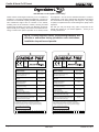
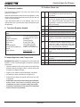
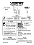
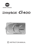
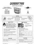
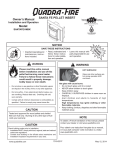
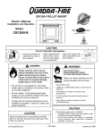
R
CASTILE & SANTA FE PELLET INSERT
Owner’s Manual
Installation and Operation
Models:
CASTILEI-CE-MBK
SANTAFEI-CE-MBK
NOTICE
• Important operating and • Read, understand and • Leave this manual with
follow these instrucparty responsible for use
maintenance instructions
for
safe
installaand operation.
tions included.
tion and operation.
WARNING
WARNING
Please read this entire manual
before installation and use of this
pellet fuel-burning room heater.
Failure to follow these instructions
could result in property damage,
bodily injury or even death.
• Do not store or use gasoline or other flam-
mable vapors and liquids in the vicinity of this
or any other appliance.
• Do not overfire - If any external part starts to
glow, you are overfiring. Reduce feed rate. Overfiring will void your warranty.
• Comply with all minimum clearances to combustibles as specified. Failure to comply may
cause house fire.
HOT SURFACES!
Glass and other surfaces are
hot during operation AND
cool down.
Hot glass will cause burns.
• Do not touch glass until it is cooled
• NEVER allow children to touch glass
• Keep children away
• CAREFULLY SUPERVISE children in same room as
fireplace.
• Alert children and adults to hazards of high
temperatures.
High temperatures may ignite clothing or other
flammable materials.
• Keep clothing, furniture, draperies and other flammable
materials away.
CAUTION
CAUTION
Fuel Type: Wood Pellets, less than 38mm in length,
6mm to 8mm in diameter.
Burning of any other type of fuel voids your warranty.
www.quadrafire.com
T
O
N RD
O A
D SC
I
D
DO NOT DISCARD THIS MANUAL
Check building codes prior to installation.
• All local regulations, including those referring to national and
European standards need to be complied with when installing
the appliance.
• Consult local fire officials or authorities having jurisdiction
about restrictions, installation inspection, and permits.
7069-101B
October 27, 2011
Castile & Santa Fe CE Insert
R
and Welcome to the Quadra-Fire Family!
Hearth & Home Technologies welcomes you to our tradition of
excellence! In choosing a Quadra-Fire appliance, you have our
assurance of commitment to quality, durability, and performance.
This commitment begins with our research of the market,
including ‘Voice of the Customer’ contacts, ensuring we make
products that will satisfy your needs. Our Research and Development facility then employs the world’s most advanced technology to achieve the optimum operation of our stoves, inserts
and fireplaces. And yet we are old-fashioned when it comes to
craftsmanship. Each unit is meticulously fabricated and surfaces
are hand-finished for lasting beauty and enjoyment. Our pledge
to quality is completed as each model undergoes a quality control
inspection. We wish you and your family many years of enjoyment in the
warmth and comfort of your hearth appliance. Thank you for
choosing Quadra-Fire.
NOTE: Consult insurance carrier, local building inspector, fire
officials or authorities having jurisdiction over restrictions,
installation inspection and permits.
R
EN 14785 - 2006
R
1445 North Highway - Colville, WA 99114 - USA
SANTA FE CE PELLET INSERT
Nominal heat output:
Puissance nominale:
Nominaal vermogen:
CO emission (at 13% O2):
Des émissions de CO (à 13% O2):
CO-uitstoot (bij 13% O2):
Efficiency:
Efficacité:
Efficiëntie:
Flue gas temperature:
Température des fumées:
Rookgastemperatuur:
Max electrical power supply:
Max approvisionnement électrique:
Max elektrische voeding:
Rated Voltage:
Tension nominale:
Nominale spanning:
Safety clearance distance (back):
Distance de dégagement de sécurité (retour):
Veiligheidsafstand afstand (terug):
Safety clearance distance (side):
Distance de dégagement de sécurité (côté):
Veiligheidsafstand afstand (zijde):
1445 North Highway - Colville, WA 99114 - USA
CASTILE CE PELLET INSERT
Nominal heat output:
Puissance nominale:
Nominaal vermogen:
CO emission (at 13% O2):
Des émissions de CO (à 13% O2):
CO-uitstoot (bij 13% O2):
Efficiency:
Efficacité:
Efficiëntie:
Flue gas temperature:
Température des fumées:
Rookgastemperatuur:
Max electrical power supply:
Max approvisionnement électrique:
Max elektrische voeding:
Rated Voltage:
Tension nominale:
Nominale spanning:
Safety clearance distance (back):
Distance de dégagement de sécurité (retour):
Veiligheidsafstand afstand (terug):
Safety clearance distance (side):
Distance de dégagement de sécurité (côté):
Veiligheidsafstand afstand (zijde):
Max: 7,7 kW
Min: 3,0 kW
Max: 0,003%
Min: 0,018%
Max: 83,6%
Min: 82,7%
161°C
470 W
230 V - 50 Hz
N/A
410 mm
Use only recommended fuels. Utilisez uniquement des combustibles
recommandés. Gebruik alleen aanbevolen brandstoffen.
Read and follow the operating instructions! Lisez et suivez les
instructions d'utilisation! Lees en volg de gebruiksaanwijzing!
SERIAL NO. / NUMÉRO DE SÉRIE / SERIENUMMER
SERIAL NO. / NUMÉRO DE SÉRIE / SERIENUMMER
007031
007029
2011 2012 2013 JAN FEB MAR APR MAY JUN JUL AUG SEP OCT NOV DEC
7069-100
Page 2
EN 14785 - 2006
7069-101B
2011 2012 2013 JAN FEB MAR APR MAY JUN JUL AUG SEP OCT NOV DEC
7071-100
October 27, 2011
R
Castile & Santa Fe CE Insert
Safety Alert Key:
• DANGER! Indicates a hazardous situation which, if not avoided will result in death or serious injury.
• WARNING! Indicates a hazardous situation which, if not avoided could result in death or serious injury.
• CAUTION! Indicates a hazardous situation which, if not avoided, could result in minor or moderate injury.
• NOTICE: Indicates practices which may cause damage to the appliance or to property.
TABLE OF CONTENTS
Congratulations................................................................2
Sample of Safety/Serial Numer Label..............................2
Safety Alert Key................................................................3
Limited Warranty..............................................................4-5
C. Tools & Supplies Needed..................................19
D. Inspect Appliance and Components..................19
E. Pre-Burn Checklist.............................................19
Section 1: Listing and Code Approvals
A.
B.
C. D.
E.
A.
B.
C.
D.
Section 6: Dimensions & Clearances
Appliance Certifications.....................................6
Glass Specifications...........................................6
Electrical Rating.................................................6
Specifications.....................................................6
User’s Guide
Section 2: Operating Instructions
A.
B.
C.
D.
E.
F.
G.
H. I.
J.
K. A.
B.
C.
D.
A. Frequently Asked Questions..............................17
Installer’s Guide
Section 5: Getting Started
A. Design, Installation & Location
Considerations and Floor Support.....................18
B. Thermostat Location..........................................19
October 27, 2011
A.
B.
C.
D.
E.
F.
Venting Termination Requirements...................22
Avoiding Smoke and Odors...............................22-23
Negative Pressure.............................................23
Draft...................................................................23
Chimney & Exhaust Connection........................24
Pellet Venting Charts.........................................25
Section 8: Vent Systems
Proper Shutdown Procedures............................12
Quick Reference Maintenance Chart.................12
General Maintenance & Cleaning......................12-15
High Ash Fuel Content Maintenance.................16
Section 4: Troubleshooting for Homeowner
Section 7: Vent Information
Fire Safety..........................................................7-8
Combustible/Non-Combustible Material............8
Fuel Material & Fuel Storage.............................8
General Operation Information..........................9
Before Your First Fire.........................................9
Filling the Hopper with Fuel...............................9
Starting Your First Fire.......................................10
Fire Characteristics............................................10
Flame Height Adjustment (Feed Rate)..............10
Ignition Cycles....................................................11
Clear Space.......................................................11
Section 3: Maintaining & Servicing Appliance
Appliance Dimensions.......................................20
Clearance to Combustibles,
Masonry & Zero Clearance................................21
Minimum Opening for Masonry and
Factory-Built Fireplace.......................................21
Floor Protection..................................................21
Prefabricated Metal Chimney.............................21
A. Full Reline with Outside Air-Horizontal..............26
B. Full Reline without Outside Air-Vertical..............27
A.
B.
C.
D. E.
F.
G.
H.
I.
J.
K.
Contact Information....................................................36
Section 9: Appliance Set-Up
7069-101B
Leveling System.................................................28
Outside Air Installation.......................................28
Door Handle Removal........................................29
Door Removal....................................................29
Adjustable Hearth Support.................................29
Hearth Support, Standard Surround..................30-31
Surround & Trim Set, Econo..............................31
Surround Cast Trim Set.....................................32
Panel and Trim Set............................................33
Log Set Placement (Optional)............................34
Thermostat Installation.......................................35
Page 3
Castile & Santa Fe CE Insert
Page 4
R
7069-101B
October 27, 2011
R
Castile & Santa Fe CE Insert
October 27, 2011
7069-101B
Page 5
Castile & Santa Fe CE Insert
1
R
Listing and Code Approvals
A. Appliance Certification
D. Specifications
Model
Castile or Santa Fe Pellet Insert Appliance
Type
Residential Space heating appliance fired
by wood pellets
Standard
EN 14785:2006
Distance to Adjacent
Combustion Materials:
Standoff to Side: 410mm
Standoff to Header: 305mm
CO Concentration at 13% Max: 0.003%
O2 (mg/m3):
Min: 0.030%
Hearth & Home Technologies
1445 North Highway
Colville, WA 99114
United States
2011
Flue Gas Temperature:
161°C
*Thermal Output:
Max: 6.3 kW
Min: 3.0 kW
Energy Efficiency:
Max: 75.1%
Min: 75.0%
Heating Capacity:
220m2 to 350m2
Hopper Capacity:
18 kg
Fuels:
Wood Pellets, less than
38mm in length, 6mm to
8mm in diameter
Shipping Weight:
109 kg, add 18 kg when the
hopper is full
B. Glass Specifications
This appliance is equipped with 5mm ceramic glass. Replace
glass only with 5mm ceramic glass. Please contact your
dealer for replacement glass.
*Thermal output will vary, depending on the type of fuel
you use in your appliance. Consult your Quadra-Fire
dealer for best results.
WARNING! Risk of Fire! Hearth & Home Technologies disclaims any responsibility for, and the warranty and agency
listing will be voided by the following actions.
C. Electrical Rating
230 VAC, 50 Hz, Start 2.80 Amps, Run 0.80 Amps
NOTE: Some generator or battery back-up systems may
not be compatable with the micro-processor electronics on this appliance. Please consult the power supply
manufacturer for compatable systems.
DO NOT:
• Install or operate damaged appliance
• Modify appliance
• Use as an incinerator or any other different way from
which it was conceived
• Install other than as instructed by Hearth & Home
Technologies
• Operate the appliance without fully assembling all
components
• Overfire
• Install any component not approved by Hearth &
Home Technologies
• Install parts or components not Listed or approved.
Improper installation, adjustment, alteration, service or
maintenance can cause injury or property damage.
NOTICE: Hearth & Home Technologies, manufacturer
of this appliance, reserves the right to alter its products, their specifications and/or price without notice.
Page 6
For assistance or additional information, consult a qualified
installer, service agency or your dealer.
Quadra-Fire is a registered trademark of Hearth &
Home Technologies
7069-101B
October 27, 2011
R
Castile & Santa Fe CE Insert
2
User’s Guide
Operating Instructions
WARNING
HOT SURFACES!
Glass and other surfaces are hot during operation AND cool down.
Hot glass will cause burns.
• Do not touch glass until it is cooled
• NEVER allow children to touch glass
• Keep children away
• CAREFULLY SUPERVISE children in same room as appliance.
• Alert children and adults to hazards of high temperatures.
High temperatures may ignite clothing or other flammable materials.
• Keep clothing, furniture, draperies and other flammable materials away.
WARNING! Do not operate appliance before reading and
understanding the operating instructions in the Owner’s
Manual. Failure to operate appliance according to operating
instructions could cause fire or injury.
October 27, 2011
7069-101B
Page 7
Castile & Santa Fe CE Insert
R
A. Fire Safety
Clinkers
To provide reasonable fire safety, the following should be
given serious consideration:
Minerals and other non-combustible materials such as sand
will turn into a hard, glass-like substance called a clinker when
heated in the firepot.
• Install at least one smoke detector and CO monitor on each
floor of your home.
• Locate detectors away from the heating appliance and close
to the sleeping areas. • Follow the detector’s manufacturer’s placement and
installation instructions and maintain regularly. • Conveniently locate a fire extinguisher to contend with small
fires.
• In the event of a hopper fire:
• Evacute the house immediately.
• Notify fire department.
B.Combustible/Non-Combustible Materials
• Combustible Material
Material made of or surfaced with wood, compressed
paper, plant fibers, plastics, or any material capable
of igniting and burning, whether flame-proofed or not,
plastered or unplastered.
• Non-combustible Material
Material which will not ignite and burn. Such materials are
those consisting entirely of steel, iron, brick, tile, slate,
glass or plasters, or any combination thereof.
Trees from different areas will vary in mineral content. That
is why some fuels produce more clinkers than others.
Moisture
Always burn dry fuel. Burning fuel with high moisture content
takes heat from the fuel and tends to cool the appliance,
robbing heat from your home. Damp pellet fuel can clog the
feed system.
Size
• Pellets are either 6 or 8mm in diameter
• Length should be no more that 38mm
• Pellet lengths can vary from lot to lot from the same
manufacturer
• Due to length variations, the flame height (feed rate) may
need adjusting occasionally. See page 10 for instructions.
Performance
• Higher ash content requires the ash drawer to be emptied
more frequently
• Hardwoods require more air to burn properly
• Premium wood pellets produce the highest heat output.
• Burning pellets longer than 38mm can cause an inconsistent
fuel feed rate and/or missed ignitions.
CAUTION! Tested and approved for wood pellets. Burning
of any other type of fuel voids your warranty.
• Firestop Non-combustible Sealant Material
Sealants which will not ignite and burn.
Storage
C. Fuel Material and Fuel Storage
Pellet fuel quality can greatly fluctuate. We recommend that
you buy fuel in multi-ton lots whenever possible. However,
we do recommend trying various brands before purchasing
multi-ton lots to ensure your satisfaction.
Fuel Material
• Wood pellets should be left in their original sealed bag until
using to prevent moisture absorption.
• Do not store any pellet fuel within the clearance
requirements or in an area that would hinder routine
cleaning and maintenance.
• Made from sawdust or wood by-products
• Depending on the source material it may have a high or
low ash content.
Higher Ash Content Material
• Hardwoods with a high mineral content
• Fuel that contains bark
• Standard grade pellets and high ash pellets
Lower Ash Content Material
• Softwoods
• Fuels with low mineral content
• Premium grade pellets
CAUTION! Do not burn fuel that contains an additive;
(such as soybean oil).
• May cause hopper fires
• Damage to product may result
Page 8
7069-101B
October 27, 2011
R
Castile & Santa Fe CE Insert
D. General Operating Information
WARNING
1. Thermostat Calls For Heat
Fire Hazard.
Keep combustible materials, gasoline
and other flammable vapors and liquids
clear of appliance.
• Do NOT store flammable materials in the appliance’s
vicinity.
• DO NOT USE GASOLINE, LANTERN FUEL, KEROSENE,
CHARCOAL LIGHTER FLUID OR SIMILAR LIQUIDS TO
START OR “FRESHEN UP” A FIRE IN THIS HEATER.
The appliance is like most modern furnaces; when the thermostat
calls for heat, your appliance will automatically light and deliver
heat. When the room is up to temperature and the thermostat is
satisfied, the red call light will shut off and the appliance will shut
down. The red call light is located behind the right access panel.
2. Heat Output Controls
• DO NOT BURN GARBAGE OR FLAMMABLE FLUIDS
SUCH AS GASOLINE, NAPHTHA OR ENGINE OIL.
This appliance is equipped with a heat output control switch
that has three settings or burn rates; low, medium and high. Figure 9.1.
The appliance will turn on and off as the thermostat demands. When the thermostat calls for heat, the appliance will always
start up on High. After burning approximately 4 minutes, the
appliance will then burn at the rate at which it was originally
set. If the appliance is set at one of the lower settings, it will
run quieter but takes longer to heat up an area than if it were
set at a higher burn rate. Regardless of the burn rate, when the area is warm enough to
satisfy the thermostat, the appliance will shut off.
• DO NOT USE CHEMICALS OF FLUIDS TO START THE
FIRE.
• Keep all such liquids well away from the heater while it is in
use.
• Combustible materials may ignite.
E. Before Your First Fire
1. First, make sure your appliance has been properly installed
and that all safety requirements have been met. Pay
particular attention to the fire protection, venting and
thermostat installation instructions.
2. Double check that the ash drawer and firebox are empty!
3. Close the front door. CAUTION
High
Med
Low
Tip of thermocouple must be in contact with the
inside end of the thermocouple cover.
Missed ignitions can occur.
Reset
Button
Figure 9.1
F. Filling the Hopper with Fuel
a. Open the hopper lid and pull the lid towards you. b. Do not over fill the hopper. The lid must be completely
closed to maintain proper vacuum and for the feed motor
to operate. An error message will appear on the wall
control if the lid is not properly closed.
c. Remove any sawdust or fuel from the lid gasket after
refilling hopper.
d. Do not leave any part of the fuel bag on the appliance
after refilling hopper.
e. Store fuel away from the appliance to maintain proper
safe air clearance to combustibles.
October 27, 2011
7069-101B
Page 9
Castile & Santa Fe CE Insert
R
G. Starting Your First Fire
1. A thermostat is required for proper operation of this
appliance. At this time, fill the hopper with pellets, set
the thermostat to its lowest setting. Plug the power cord
into nearby outlet.
2. The exhaust blower will stay on for approximately 18
minutes even though the thermostat is not calling for
heat. This is normal.
3. Locate the heat output control switch on the lower right
side of the firebox behind decorative front door. Set to the
HIGH setting and then adjust the thermostat to its highest
setting. The red call light will be on which is located on
the top of the junction box behind the right access panel. This indicates the thermostat is calling for heat. Figure
10.1.
4. The fuel feed system and the igniter should now be on.
5. For your first fire it will be necessary to press the reset
button once per minute until pellets start to drop into the
firepot, then press button 1 more time. This will fill the
feed system and allow the appliance to begin dropping
pellets. The appliance will continue to run as long as the
thermostat is calling for heat.
6. Once the appliance has ignited, let it burn for approximately
15 minutes, then set the thermostat to the desired room
temperature. Adjust the heat output control switch to the
desired setting.
H. Fire Characteristics
A properly adjusted fire with the heat output control button
set on “HIGH” has a short active flame pattern that extends
out of the firepot approximately 102mm. If the fire has tall flames with black tails and seems somewhat
lazy, the feed rate will need to be reduced. If the fire is not 102mm tall, increase the feed rate. A medium
and low setting will give a shorter flame. The flame will rise
and fall somewhat. This is normal.
I. Feed Rate Adjustment Instructions
The feed adjustment control rod is factory set, and should be
adequate for most fuels. The control rod will slide by only
loosening the wing screw.
However, if the flame height is too high or too low, you will
need to adjust the feed rate. Wait until the appliance has been
burning for 15 minutes before making your adjustments and
allow 15 minutes for feed adjustment to take effect. Make
adjustments in approximately 12.7mm increments.
1.
Loosen the wing screw. Figure 10.2
2. Adjust the fuel adjustment control rod towards to the right
and up to increase the feed rate and flame height or to
the left and down to decrease the feed rate and flame
height.
3. Re-tighten the wing screw.
CAUTION
Feed Adjustment Control Rod
Odors and vapors released during initial operation.
• Curing of high temperature paint.
• Open windows for air circulation.
Wing Nut
Odors may be irritating to sensitive individuals.
Fuse
Control Box
Red Call
Light
ue
Bl
t
gh
Li
r
/G
ed
R
Figure 10.2
m
/A
Heat Output
Switch
be
ht
ig
rL
n
ee
Set Screw
Power Cord
Outlet
Reset Button
Junction Box
Thermostat
Block
Figure 10.1
Page 10
7069-101B
October 27, 2011
R
Castile & Santa Fe CE Insert
J. Ignition Cycles
K. Clear Space
1. At the beginning of each ignition cycle, it is normal to see
some smoke in the firebox. The smoke will stop once
the fire starts.
2. The convection blower will automatically turn on after your
appliance has reached the set temperature. This blower transfers heat from your appliance into the
room, and will continue to run after the thermostat has
stopped calling for heat until the appliance has cooled
down.
3. Occasionally the appliance may run out of fuel and shut
itself down. When this happens, the red call light will be
on. See Figure 10.1 on page 10.1.
To restart it, fill the hopper and press the reset button. When you press the reset button the red call light will go
out. Release the button and the light will come back on. You should see a fire shortly. If not, follow the instructions on page 10, “Starting Your
First Fire”.
WARNING! RISK OF FIRE! Do NOT place combustible
objects in front of the appliance. High temperatures may
ignite clothing, furniture or draperies. Maintain a minimum
clearance of 914mm in front of appliance.
Mantel: Avoid placing candles and other heat-sensitive
objects on mantel or hearth. Heat may damage these
objects.
NOTICE: Clearances may only be reduced by means approved by the regulatory authority having jurisdiction.
WARNING! RISK OF FIRE! Keep combustible materials,
gasoline and other flammable vapors and liquids clear of
appliance.
• Do NOT store flammable materials in the appliance’s
vicinity.
• Do NOT use gasoline, lantern fuel, kerosene, charcoal
lighter fluid or similar liquids to start or “freshen up” a fire
in this heater.
Keep all such liquids well away from the heater while it is in
use as combustible materials may ignite.
WARNING
Fire Risk
Do NOT operate appliance:
• With appliance door open.
• Firepot floor open.
• Cleaning slide plates open.
Do NOT store fuel:
• Closer than required clearances to combustibles to appliance
• Within space required for loading or ash
removal.
Back side of Firepot
Firepot floor left open
Figure 11.1 - DO NOT LEAVE FIREPOT FLOOR OPEN
October 27, 2011
7069-101B
Page 11
Castile & Santa Fe CE Insert
3
R
Maintaining & Servicing Your Appliance
C. General Maintenance
A. Proper Shutdown Procedure
1. Types of Fuel
CAUTION
Depending on the type of fuel you are burning will dictate how
often you have to clean your firepot. Shock and Smoke Hazard
If the fuel you are burning has a high dirt or ash content it may
be necessary to clean the firepot more than once a day. • Turn down thermostat, let appliance completely
cool and exhaust blower must be off. Now you
can unplug appliance before servicing.
• Smoke spillage into room can occur if appliance
is not cool before unplugging.
Dirty fuel will cause clinkers to form in the firepot. A clinker is
formed when dirt, ash or a non-burnable substance is heated to
1093°C and becomes glass-like. • Risk of shock if appliance not unplugged before
servicing appliance.
Follow the detailed instructions found in this
section for each step listed in the chart below.
Clinker
B. Quick Reference Maintenance Chart
Cleaning or Inspection
Figure 12.1 - Clinker
Frequency
Daily Weekly Monthly
Ash Pan/Drawer
Every 5 bags of fuel depending on the fuel type or ash
build-up
OR
X
Ash Removal from Firebox
Every 5 bags or more frequently depending on the fuel
type or ash build-up
OR
X
Beneath Heat Exchanger
Every 1 ton of fuel
OR
Blower, Combustion (Exhaust)
More frequently depending on
the fuel type
OR
Blower, Convection
Every 25 bags or more frequently depending on the fuel
type
OR
X
Door Latch Inspection
Prior to heating season
OR
X
Firebox - Prepare for Non-Burn Season
At end of heating season
OR
Firepot - Burning pellets - hardwood
Every 3 bags
OR
X
Firepot - Burning pellets - softwood
Every 5 bags
OR
X
Glass
When clear view of firepot
becomes obscure
OR
X
Heat Exchanger & Drop Tube
Every 15 bags of fuel
OR
X
Hopper
Every 50 bags of fuel or when
changing fuel types
OR
Venting System
More frequently depending on
the fuel type
OR
Yearly
X
X
X
X
X
NOTICE: These are recommendations. Clean more frequently if you encounter heavy build-up of ash at
the recommended interval or you see soot coming from the vent. Not properly cleaning your
appliance on a regular basis will void your warranty.
Page 12
7069-101B
October 27, 2011
R
Castile & Santa Fe CE Insert
4. Cleaning Ash Pan/Drawer
2. Cleaning Firepot with Cleaning Rod & Firepot
Clean-Out Tool
•
•
•
Frequency: Daily or more often as needed
By: Homeowner
a.The appliance must be in complete shutdown and
cool and the exhaust blower off. NOTE: If you are
just cleaning the firepot, there is no need to unplug the
insert.
b.Pull firepot cleaning rod OUT and IN a couple of times
to help shake debris loose. See Figure 12.1 on page
12.
•
If rod is hard to pull, it may be necessary to use your
firepot clean-out tool to chip away material that has built
up on the bottom plate of the firepot and to push out any
clinkers. Larger clinkers may have to be removed from
the top of the firepot. Corn clinkers can be especially
difficult to break up.
c.The firepot floor plate must be fully closed when finished. See Figure 11.1 on page 11.
Frequency: Weekly or every 5 bags or more
frequently depending on ash build
By: Homeowner
Locate the ash pan/drawer underneath the firepot and
slide the ash drawer straight out. Empty into a noncombustible container and re-install ash pan/drawer.
5. Disposal of Ashes
•
•
Frequency: As needed
By: Homeowner
Ashes should be placed in a metal container with a
tight-fitting lid. The closed container of ashes should
be placed on a non-combustible floor or on the ground,
well away from all combustible materials, pending final
disposal.
If the ashes are disposed of by burial in soil or otherwise
locally dispersed, they should be retained in the
closed container until all cinders have been thoroughly
cooled.
3. Ash Removal from Firebox
•
•
Frequency: Weekly or 5 bags or more frequently
depending on ash build-up
By: Homeowner
WARNING
a.There must not be any hot ashes in the firebox during
cleaning so allow the appliance to completely cool. The firebox ash should be removed every time the
exhaust path is cleaned. Frequent cleaning of the ash
in the firebox will help slow down the build-up of ash
in the exhaust blower and vent system.
b.Plug in your appliance, if unplugged, and turn the
thermostat on and immediately shut it off to start the
exhaust blower on its cycle time. It will pull fly ash out
the exhaust instead of into the room.
c.Open door. There are 2 cleaning slide plates to the
left and right of the firepot with finger holes. Pull both
slide plates out and sweep the remaining ash from the
firebox into the 2 open holes. A paint brush works well
for this. Close slide plates.
d. This ash is deposited in the same ash drawer as the
firepot debris. The ash drawer should be emptied every
time you clean the firebox. Remember to place the ash
and debris into a metal or non-combustible container.
e.The 2 cleaning slide plates must be fully closed when
cleaning is complete.
October 27, 2011
7069-101B
Disposal of Ashes
• Ashes should be placed in metal container
with tight fitting lid.
• Ashes should be retained in closed container
until all cinders have thoroughly cooled.
WARNING
Fire Risk
• NEVER pull firepot cleaning rods or cleaning
slide plates when appliance is operating. Hot
pellets may fall into ashpan and may start a
fire or have mis-starts due to lack of vacuum.
WARNING
Fire Risk.
• The cleaning slide plates must be fully
CLOSED when appliance is operating. Hot
pellets may fall into ash pan and start a fire.
Page 13
Castile & Santa Fe CE Insert
R
6. Cleaning Heat Exchanger Chambers & Drop Tube
8. Cleaning the Hopper
•
•
•
•
Frequency: Weekly or every 15 bags or more fre
quently depending on ash build-up
By: Homeowner
Frequency: Monthly or after burning 50 bags of fuel
By: Homeowner
After burning approximately 1 ton of fuel you will need
to clean the hopper to prevent sawdust build-up. WARNING
A combination of sawdust and pellets on the auger
reduces the amount of fuel supply to the firepot. This
can result in nuisance shutdowns and mis-starts.
Heat exchanger cleaning rods may be warm
to the touch. For safety purposes wear
gloves.
Do not pull heat exchanger cleaning rods
while appliance is operating.
Push cleaning rods IN when done, DO NOT
leave cleaning rods OUT. Injury can occur.
The amount of ash buildup in the firepot will be a good
guide to determine how often you should clean the heat
exchangers.
a. Allow the appliance to completely cool down before
pulling the cleaning rods. Turn the thermostat on and
then immediately off to start the exhaust blower on its
cycle time. It will pull fly ash out the exhaust instead
of into the room.
b. Locate the 2 exposed rods directly underneath the heat
exchanger tubes. Figure 14.1.
c.To clean, pull the rods straight out until it stops,
approximately 203mm. Slide the rods OUT and IN a
couple of times.
a. The appliance must be in complete shutdown. Allow the appliance to completely cool down.
b. Empty the hopper of any remaining pellets.
c. Vacuum the hopper and feed tube.
NOTE: Hearth & Home Technologies recommends to
use a heavy duty vacuum cleaner specifically
designed for solid fuel appliance cleaning.
9. Cleaning the Glass
•
•
Frequency: When clear view of the firepot becomes
obscure
By: Homeowner
a. Appliance must be completely cool before cleaning
glass.
b. Vacuum fly ash from glass and door rope.
c.Use a damp paper towel or any non-abrasive glass
cleaner. Wipe off with dry towel.
10 Heat Exchanger Tubes
CAUTION
Handle glass assembly with care.
When cleaning glass:
• Avoid striking, scratching or
slamming glass.
• Do NOT clean glass when hot.
Cleaning
Rods
• Do NOT use abrasive cleaners.
Figure 14.1
• Refer to maintenance instructions.
7. Cleaning Beneath Heat Exchanger
•
•
Frequency: Monthly or after burning 1 ton of fuel
By: Homeowner
a. Be sure the appliance is allowed to cool, has been
unplugged and the exhaust blower is off
b. A more thorough cleaning is needed to remove the
excess ash that is left behind from the use of the
cleaning rods for the heat exchanger tubes. c. The ash will be resting on the back of the baffle. This
will require removing the cast baffle.
Page 14
7069-101B
WARNING
Handle glass with care.
• Inspect the gasket to ensure it is
undamaged.
• Do NOT strike, slam or scratch glass.
• Do NOT operate appliance with glass assembly removed.
• Do NOT operate with glass cracked, broken or
scratched.
October 27, 2011
R
Castile & Santa Fe CE Insert
10. Soot and Fly Ash: Formation & Need for Removal
in Exhaust Venting System.
•
•
Frequency: Yearly or more frequently depending on
ash build-up.
By: Qualified Service Technician/Homeowner
Be sure the appliance is allowed to cool, has been
unplugged and the exhaust blower is off.
The products of combustion will contain small particles
of fly ash. The fly ash will collect in the exhaust venting
system and restrict the flow of the flue gases. 14. Preparing Firebox for Non-Burn Season
•
•
Frequency: Yearly at the end of the heating season
By: Homeowner
a.Be sure the appliance is allowed to cool, has been
unplugged and the exhaust blower is off.
b.Remove all ash from the firebox and vacuum thoroughly.
c. Paint all exposed steel, including cast-iron. At start-up if there is incomplete combustion, or if there
is a shutdown or incorrect operation of the appliance it
will lead to some soot formation. This will collect in the
exhaust venting system.
• Use the Touch-Up paint supplied with the appliance;
or;
• Purchase paint from your local dealer. • Must use a high-temperature paint made specificially for heating appliances.
The venting (chimney) system may need to be cleaned at
least once a year or more often depending upon the quality of your fuel or if there is a lot of horizontal pipe sections. Ash will build up more quickly in the horizontal sections.
11. Door Latch Inspection
•
•
Frequency: Prior to heating season or monthly during
heating season
By: Homeowner
The door latch is non-adjustable but the gasketing between
the glass and firebox should be inspected periodically to make
sure there is a good seal.
12. Cleaning Combustion Blower - Requires No
Lubrication
•
•
•
Frequency: Yearly or as needed
By: Qualified Service Technician
Task: Contact your local dealer
13. Cleaning Convection Blower - Requires No
Lubrication
•
•
•
Frequency: Monthly or every 25 bags or more fre
quenly depending on operating environment
By: Qualified Service Technician
Task: Contact your local dealer.
October 27, 2011
7069-101B
Page 15
Castile & Santa Fe CE Insert
R
D. High Ash Fuel Content Maintenance
•
•
Frequency: As needed
By: Homeowner
Poor quality pellet fuel, or lack of maintenance, can create
conditions that make the firepot fill quickly with ashes and
clinkers. This condition makes the appliance susceptible to overfilling
the firepot with pellets which may result in smoking, sooting
and possible hopper fires. Figure 16.1 shows an example
where the firepot overfills, pellets back up into the feed tube
and ash has accumulated in the firebox. Pellets Back Up
In Feed Tube
Firepot Overfills
Ash Build Up in Firebox
Figure 16.1
An inefficient and non-economical method of burning of fuel
caused by poor quality pellet fuel is shown in Figure 16.2.
The correct flame size when good quality, premium pellet
fuel is burned is shown in Figure 16.3.
Incorrect
If the ash buildup exceeds the half way point in the firepot
IMMEDIATE ATTENTION AND CLEANING IS REQUIRED.
WARNING
Fire Risk.
• High ash fuels, or lack of maintenance, can
cause the firepot to overfill. Follow proper
shutdown procedure if ash buildup exceeds
half way point in firepot.
• Failure to do so could result in smoking,
sooting and possible hopper fires.
Tall, Lazy Flame, Orange in Color
Figure 16.2
Correct
Correct Flame Size, Yellow/White in Color
Figure 16.3
Page 16
7069-101B
October 27, 2011
R
Castile & Santa Fe CE Insert
4
Troubleshooting for Homeowner
A. Frequently Asked Questions
ISSUES
SOLUTIONS
1. Metallic noise.
1. Noise is caused by metal expanding and contracting as
it heats up and cools down, similar to the sound produced by a furnace or heating duct. This noise does not
affect the operation or longevity of your appliance.
2. White ash buildup on glass.
2. This is normal. Clean the glass using any non-abrasive
glass cleaner.
3. Glass has buildup of black soot
3. Excessive build-up of ash. See solution #4. The lower
burn settings will produce more ash, the higher burn
settings produce less. The more it burns on low the
more frequent cleaning of the glass is required.
4. Glass has turned dirty.
3. Excessive build up of ash. The lower burn settings will
produce more ash, the higher burn settings produce
less. The more it burns on low the more frequent cleaning of the glass is required.
5. Fire has tall flames with black tails and is lazy.
4. The feed rate needs to be reduced or the firepot needs
cleaning. Heat exchanger or exhaust blower needs
cleaning.
6. Smokey start-up or puffs of smoke from the airwash. 5. Either the firepot is dirty or there is too much fuel at
start-up and not enough air. Close down feed rate 1/4
(6mm) inch at a time until this no longer happens.
6. Large flame at start-up.
6. This is normal. Flame will settle down once the fire is
established.
NOTICE: Odors and vapors are released during initial operation due to the curing of high temperature paint. Open windows for air circulation. Odors may be irritating to sensitive individuals.
October 27, 2011
7069-101B
Page 17
Castile & Santa Fe CE Insert
5
Getting Started
R
Installer’s Guide
A. Design, Installation & Location Considerations
Since pellet exhaust can contain ash, soot or sparks, you
must consider the location of:
1. Appliance Location
•
•
•
•
•
•
NOTICE: Check building codes prior to installation.
• Installation MUST comply with all local building codes
and regulations including those referring to national and
European standards.
• Consult insurance carrier, local building inspector, fire
officials or authorities having jurisdiction over restrictions,
installation inspection and permits.
It is a good idea to plan your installation on paper, using exact
measurements for clearances and floor protection, before
actually beginning the installation. Location of the appliance
and chimney will affect performance.
Consideration must be given to:
• Safety, convenience, traffic flow
• Placement of the chimney and chimney connector and to
minimize the use of chimney offsets. • Place the appliance where there will be a clear passage
for a Listed chimney through the ceiling and roof (vertical) or through exterior wall (horizontal). • Installing the required outside air kit will affect the location of the vent termination.
Recommended Location:
• Above peak
Windows
Air Intakes
Air Conditioner
Overhang, soffits, porch roofs, adjacent walls
Landscaping, vegetation
Horizontal or vertical vent termination
When locating vent and venting termination, the ideal location is to vent above roof line when possible. This minimizes the affects of wind loading.
2. Floor Support
The supporting floor under the appliance must be able
to handle the weight of the appliance, fuel load and the
weight of the chimney.
Ensure that your floor will suport these weights prior to installation. Add sufficient additional support to meet this
weight requirment prior to installation. The weight of this
appliance is 109 kg and with a full hopper of fuel weighing
18 kg, the total for the appliance and fuel is 137 kg.
WARNING! Risk of Fire Damaged parts could impair safe
operation. Do NOT install damaged, incomplete or substitute
components.
Recommended Location:
• Above peak
• Inside heated space
Marginal Location:
• Below peak
Marginal Location:
• Wind loading possible
Location NOT recommended:
• Not the highest point of the roof
• Wind loading possible
Recommended:
• Insulated exterior chase
in cooler climates
Location NOT recommended:
• Too close to tree
• Below adjacent structure
• Lower roof line
• Avoid outside wall
Windward
Leeward
Recommended:
Outside Air Intake
on windward side
Multi-level Roofs
NOT recommended:
Outside Air Intake
on leeward side
Figure 18.1
Page 18
7069-101B
October 27, 2011
R
Castile & Santa Fe CE Insert
B. Thermostat Location
E. Pre-Burn Check List
The thermostat’s location will have some effect on the
appliance’s operation. 1.
When the thermostat is located close to the appliance, it may
require a slightly higher temperature setting to keep the rest
of the house comfortable. Place the appliance in a location near the
final installation area and follow the procedures below:
2.
Open the appliance and remove all the parts
and articles packed inside the Component
Pack. Inspect all the parts and glass for shipping damage. Contact your dealer if any irregularities are noticed.
3.
All safety warnings have been read and followed.
4.
This Owner’s Manual has been read.
5.
Floor protection requirements have been met.
6.
Venting is properly installed.
7.
The proper clearances from the appliance and
chimney to combustible materials have been
met.
8.
The masonry chimney is inspected by a professional and is clean, or the factory built metal
chimney is installed according to the manufacturer’s instructions and clearances.
9.
The chimney meets the required minimum
height.
10.
All labels have been removed from the glass
door.
D. Inspect Appliance and Components
11.
Plated surfaces have been wiped clean, if
applicable.
WARNING! Risk of Fire! Damaged parts could impair safe
operation. Do NOT install damaged, incomplete or substitute
components.
12.
Thermostat or remote has been installed.
13.
A power outlet is available nearby.
If the thermostat location is in an adjacent room or on a
different floor level, you will notice higher temperatures near
the appliance.
C. Tools And Supplies Needed
Tools and building supplies normally required for installation.
Reciprocating Saw
Hammer
Phillips Screwdriver
Tape Measure
Plumb Line
Level
Framing Material
Hi-temp Caulking Material
Gloves
Safety Glasses
7/16 inch Socket Wrench
(or 10mm 6 pt or 11mm 6
pt socket)
Framing Square
Electric Drill & Bits
Self-Tapping Screws
Outside Air Required
Class L or PL Pellet Vent
May also need:
Vent Support Straps
• Open the appliance and remove all the parts and articles
packed inside the Component Pack. Inspect all the parts
and glass for shipping damage. • Report to your dealer any parts damaged in shipment.
• All labels have been removed from the glass door.
• Plated surfaces have been wiped clean with a soft cloth,
if applicable.
• Read all the instructions before starting the installation.
Follow these instructions carefully during the
installation to ensure maximum safety and benefit.
• Follow pipe manufacturer instructions for installation
and air clearance requirments.
October 27, 2011
7069-101B
Page 19
Castile & Santa Fe CE Insert
6
R
Dimensions and Clearances
A. Appliance Dimensions
28-7/8”
23-5/8”
707mm
(733mm)
(600mm)
594mm
8”
(203mm)
203mm
CL
21-1/2”
819mm
(546mm)
Figure 20.1 - Top View
629mm
Figure 20.4 - Top View
483mm
249mm
330mm
25-3/8”
(645mm)
23”
(584mm)
12-3/4”
(324mm)
51mm
Figure 20.2 -Side View
8-5/8”
(219mm)
Figure 20.5 -Side View
A
B
Figure 20.6- Front View
Figure 20.3- Front View
Overall Size
A
B
Metal Surround w/Cast Trim, STD
1080mm
762mm
Metal Surround w/Cast Trim, LRG
1219mm
864mm
Metal Surround w/Standard Trim, STD
1092mm
787mm
Metal Surround w/Standard Trim, LRG
1294mm
864mm
Panel
A
B
Standard
762mm
1016mm
Large
838mm
1270mm
SANTA FE ONLY
CASTILE ONLY
Page 20
7069-101B
October 27, 2011
R
Castile & Santa Fe CE Insert
B. Masonry and Factory-Built Fireplaces *
(Shown on a CASTILE INSERT)
D. Floor Protection
Maximum Mantel Depth: 12 inches (305mm)
Floor protection hearth extension from
door opening
6
152
F
Floor protection to the side of door
opening
6
152
E. Prefabricated Metal Chimney
C
Side Wall
B
Millimeters
E
Face
Trim
Mantel
Inches
The chimney can be new or existing, masonry or prefabricated
and must meet the following minimum requirements:
•M ust be minimum 152mm inside diameter of high
temperature chimney listed to UL 103 HT (2100oF).
•Must use components required by the manufacturer for
installation.
•Must maintain clearances required by the manufacturer
for installation.
•Refer to manufacturers instructions for installation
•This insert is listed to UL 1482 Standard and is approved
for installation into listed factory-built zero clearance fireplaces listed to UL 127 conforming to the following specifications and instructions:
D
A
E
F
Figure 22.1
Inches
Millimeters
A Insert side to combustible side wall
16
406
B Insert top to mantel
12
305
C Insert top to maximum. 2-1/4 inch
4-3/4
121
D Insert side to maximum. 2-1/4 inch
10
254
(57mm) face trim
(57mm) face trim
* the Castile and Santa Fe inserts are only intended
for installation into a masonry or factory built fireplace
C. Minimum Opening for Masonry and
Factory-Built Fireplaces
•The original factory-built clearance fireplace chimney
cap must be re-installed after installing the approved
chimney liner meeting type UL 103 HT requirements
(2100°F) per UL 1777.
•If the chimney is not listed as meeting HT requirements,
or if the factory built fireplace was tested prior to 1998, a
full height listed chimney liner must be installed from the
appliance flue collar to the chimney top.
•The liner must be securely attached to the insert flue collar
and the chimney top.
•The air flow of the factory-built zero-clearance fireplace
system must not be altered. The flue liner top support
attachment must not reduce the air flow for the existing
air-cooled chimney system.
B
C
A
D
Figure 22.2
Location
1. Secure the fireplace damper in the open position. If
this cannot be accomplished, it will be necessary to
remove the damper.t
2.Seal damper area of chimney around chimney
connector with a high temperature sealant or seal
insert against the face of the fireplace.
3.Both methods must be removable and replaceable
for cleaning and re-installation.
Millimeters (Castile/Santa Fe)
A
Rear Width
600/ 610
B
Depth
432/ 406
C
Height
540/ 591
D
Front Width
714/ 743
October 27, 2011
•No dilution air is allowed to enter the chimney.
7069-101B
Page 21
Castile & Santa Fe CE Insert
7
R
Vent Information
B. Avoiding Smoke and Odors
A. Venting Termination Requirements
CAUTION
Do not terminate vent in any enclosed or semi-enclosed
area such as a carport, garage, attic, crawl space, under a
sun deck or porch, narrow walkway or closely fenced area,
or any location that can build up a concentration of fumes
such as a stairwell, covered breezeway, etc.
1. Termination must exhaust above air inlet elevation. It is
strongly recommended that at least 1.5m of vertical
pipe be installed when appliance is vented directly
through a wall. This will create a natural draft, which
will help prevent the possibility of smoke or odor venting
into the home during a power outage. It will also keep
exhaust from causing a nuisance or hazard by exposing
people or shrubs to high temperatures. The safest and
preferred venting method is to extend the vent vertically
through the roof.
2. Distance from doors and opening windows, or gravity or
ventilation air inlets into building:
a. Not less than 1.2m below;
b. Not less than 1.2m horizontally from;
c. Not less than 305mm above.
3. Distance from permanently closed windows;
a.Not less than 305mm below; horizontally from or
above.
4. Distance between bottom of termination and grade should
be 305mm minimum. This is conditional upon plants in
the area, and nature of grade surface. The grade surface must be a non-combustible material (i.e., rock, dirt). The grade surface must not be lawn. Distance between
bottom of termination and public walkway should be 2.13m minimum.
5. Distance to combustible materials must be 610mm
minimum. This includes adjacent buildings, fences,
protruding parts of the structure, roof overhang, plants
and shrubs, etc.
6. Termination Cap Location (Home Electrical Service)
• Side-to-side clearance is to be the same as minimum
clearance to vinyl inside corners.
• Clearance of a termination cap below electrical service
shall be the same as minimum clearance to vinyl soffits.
• Clearance of a termination cap above electrical service
will be 305mm minimum.
Negative Pressure, Shut-Down and Electrical Power
Failure
To reduce the probability of back-drafting or burn-back in
the pellet appliance during power failure or shut down conditions, it must be able to draft naturally without exhaust
blower operation. Negative pressure in the house will resist this natural draft
if not accounted for in the pellet appliance installation.
Heat rises in the house and leaks out at upper levels. This
air must be replaced with cold air from outdoors which
flows into lower levels of the house. Vents and chimneys into basements and lower levels of the
house can become the conduit for air supply and reverse
under these conditions.
Outside Air
An outside air kit is recommended in all installations. The
Outside Air Kit must be ordered seperately.
Per your local building codes, consideration must be given
to combustion air supply to all combustion appliances. Failure to supply adequate combustion air for all appliance
demands may lead to backdrafting of those and other
appliances. When the appliance is roof vented (strongly recommended): The air intake is best located on the exterior wall oriented towards the prevailing wind direction during the
heating season.
When the appliance is side-wall vented:
The air intake is best located on the same exterior wall
as the exhaust vent outlet and located lower on the wall
than the exhaust vent outlet.
The outside air supply kit can supply most of the demands
of the pellet appliance, but consideration must be given to
the total house demand. House demand may consume the air needed for the appliance. It may be necessary to add additional ventilation to
the space in which the pellet appliance is located. Consult with your local heating professional to determine
the ventilation demands for your house.
• Location of the vent termination must not obstruct or
interfere with access to the electrical service.
Page 22
7069-101B
October 27, 2011
R
Castile & Santa Fe CE Insert
Vent Configurations
To reduce probability of reverse drafting during shut-down
conditions Hearth & Home Technologies strongly recommends:
• Installing the pellet vent with a minimum vertical run
of 1.52m. Preferably terminating above the roof line.
• Installing the outside air kit at least 1.22m below the
vent termination.
To prevent soot damage to exterior walls of the house and
to prevent re-entry of soot or ash into the house:
• Maintain specified clearances to windows, doors and
air inlets, including air conditioners.
• Vents should not be placed below ventilated soffits. Run the vent above the roof.
• Avoid venting into alcove locations.
• Vents should not terminate under overhangs, decks
or onto covered porches.
• Maintain minimum clearance of 305mm from the vent
termination to the exterior wall. If you see deposits
developing on the wall, you may need to extend this
distance to accommodate your installation conditions.
C.Negative Pressure
WARNING! Risk of Asphyxiation! Negative pressure can
cause spillage of combustion fumes and soot.
Negative pressure results from the imbalance of air available for the appliance to operate properly. It can be strongest in lower levels of the house.
Causes include:
• Exhaust fans (kitchen, bath, etc.)
• Range hoods
• Combustion air requirements for furnaces, water heaters
and other combustion appliances
• Clothes dryers
• Location of return-air vents to furnace or air conditioning
• Imbalances of the heating/cooling air handling system
• Upper level air leaks such as:
- Recessed lighting
- Attic hatch
- Duct leaks
October 27, 2011
To minimize the effects of negative air pressure:
• Install the outside air kit with the intake facing prevailing
winds during the heating season
• Ensure adequate outdoor air for all combustion appliances
and exhaust equipment
• Ensure furnace and air conditioning return vents are not
located in the immediate vicinity of the appliance
• Avoid installing the appliance near doors, walkways or
small isolated spaces
• Recessed lighting should be a “sealed can” design
• Attic hatches weather stripped or sealed
• Attic mounted duct work and air handler joints and seams
taped or sealed
On nominal heat output the combustion blower operates at
2053 rpm developing 0.33 m^3/s. This is the minimum requirement for the supply of combustion air. D.Draft
Draft is the pressure difference needed to vent appliances
successfully. When an appliance is drafting successfully, all
combustion byproducts are exiting the home through the
chimney.
Install through the warm airspace enclosed by the building envelope. This helps to produce more draft, especially
during lighting and die-down of the fire.
Considerations for successful draft include:
• Preventing negative pressure
• Location of appliance and chimney
To measure the draft or negative pressure on your appliance
use a magnahelic or a digital pressure gauge capable of
reading 0 - .13 inches of water column (W.C.). The appliance should be running on high for at least 15
minutes for the test.
With the stove running on high you should have a negative
pressure equal to or greater than the number given in the
chart below. If you have a lower reading than you find on
the chart, your appliance does not have adequate draft to
burn the fuel properly.
Minimum Vacuum Requirements:
.095
NOTICE: Hearth & Home Technologies assumes no
responsibility for the improper performance of the chimney
system caused by:
• Inadequate draft due to environmental conditions
• Downdrafts
• Tight sealing construction of the structure
• Mechanical exhausting devices
7069-101B
Page 23
Castile & Santa Fe CE Insert
R
E. Chimney and Exhaust Connection
CAUTION
1. Chimney & Connector: Use 76mm to102mm diameter
type "L" or "PL" venting system. It can be vented vertically
or horizontally.
2. Residential: Use 24 gauge single wall flue connector or
Listed double wall flue connector to Class A Listed metal
chimneys, or masonry chimneys meeting International Building Code (ICC) standards for solid fuel appliances.4.
INSTALL VENT AT CLEARANCES SPECIFIED BY THE
VENT MANUFACTURER.
• DO NOT CONNECT THIS UNIT TO A CHIMNEY FLUE
SERVICING ANOTHER APPLIANCE.
• DO NOT CONNECT TO ANY AIR DISTRIBUTION DUCT
OR SYSTEM.
May allow flue gases to enter the house
4. Exhaust Venting System: Secure to the appliance with
at least 2 screws 180 degrees apart. Also secure all connector pipe joints with at least 3 screws through each joint.
5. DO NOT INSTALL A FLUE DAMPER IN THE EXHAUST
VENTING SYSTEM OF THIS UNIT.
WARNING
Vent surfaces get HOT, can cause burns if
touched. Non-combustible shielding or guards
may be required.
6. DO NOT CONNECT THIS UNIT TO A CHIMNEY FLUE
SERVING ANOTHER APPLIANCE.
NOTE: All pipe must be welded seam pipe whenever possible. Seal pipe joints with high temperature silicone (260°C)
minimum rated only. Do not put silicone inside of pipe.
WARNING
Fire Risk.
Follow Chimney Connector Manufacturer’s
Instructions for Proper Installation.
ONLY use connector:
• Within the room, between appliance and ceiling or wall.
Connector shall NOT pass through:
• Attic or roof space
• Closet or similar concealed space
• Floor or ceiling
Maintain minimum clearances to combustibles
Page 24
7069-101B
October 27, 2011
R
Castile & Santa Fe CE Insert
F.Pellet Venting Charts
WARNING
The maximum horizontal venting allowed with no vertical venting attached is 219mm including one 90° elbow or two 45°
elbows. This is our recommended horizontal venting installation. Addition of any horizontal venting beyond 1219mm
Hearth & Home Technologies strong recommends a minimum
of 1524mm of additional vertical vent. Horizontal sections of
vent pipe should have a 6.35mm rise per foot.
Hearth & Home Technologies recommends any installation
requiring more than two 90° elbows, or more than 4.5m of
venting to use 102mm vent.
45° elbow is equivalent to 30.48cm of straight pipe
90° elbow is equivalent to 91.44cm of straight pipe
TWO 90º ELBOWS
Total
Minimum
Vent
Horizontal Vertical Diameter
2
5
3
3
6
3
4
7
3
5
8
3
6
9
3
7
10
4
8
11
4
9
12
4
10
13
4
11
14
4
12
15
4
13
16
4
14
17
4
15
18
4
5.00
4.00
3.00
2.00
1.00
0.00
0
2
3
4
5
6
Figure 27.1
Miniumum Vertical Vent for Two Elbows
6.00
5.00
4.00
3.00
2.00
1.00
0.00
0
1
2
3
4
5
6
Length of Horizontal Sections (M)
Figure 27.2
THREE 90º ELBOWS
Miniumum Vertical Vent for Three Elbows
Minimum Vertical Rise
(M)
Total
Minimum
Vent
Horizontal Vertical Diameter
2
11
4
3
12
4
4
13
4
5
14
4
6
15
4
7
16
4
8
17
4
9
18
4
10
19
4
11
20
4
1
Horizontal Run (M)
Minimum Vertical Rise (M)
3
3
3
3
4
4
4
4
4
4
4
4
4
4
4
4
Minimum Vertical Rise
(M)
6.00
Total
Minimum
Vent
Horizontal Vertical Diameter
0
5
6
7
8
9
10
11
12
13
14
15
16
17
18
19
• NO OTHER vent components may be used.
Substitute or damaged vent components may
impair safe operation.
Miniumum Vertical Vent for One Elbow
ONE 90º ELBOW
4
5
6
7
8
9
10
11
12
13
14
15
16
17
18
19
Fire Risk.
• Only LISTED venting components may be
used.
7.00
6.00
5.00
4.00
3.00
2.00
1.00
0.00
0
1
2
3
4
Length of Horizontal Sections (M)
Figure 27.3
NOTICE: These are guidelines for successful venting of your pellet appliance. The more vertical rise you can obtain in your system,
the better it will perform. Horizontal vent runs can accumulate ash and will need to be cleaned more often. Try to keep them as short
as possible.
October 27, 2011
7069-101B
Page 25
Castile & Santa Fe CE Insert
8
R
Venting Systems
A. Full Reline With Horizontal Outside Air
WARNING
Fire Risk.
Inspection of Chimney:
• Masonry chimney must be in good condition.
• Meets minimum standard of NFPA 211
• Factory-built chimney must be a minimum 152mm
UL103 HT.
CAUTION
Never draw outside combustion air from:
• Wall, floor or ceiling cavity
• Enclosed space such as an attic or garage
NOTE; Use metal plate around
exhaust vent pipe and seal all
edges with non-flammable insulation such as , mineral wool or
ceramic.
NOTE; Use metal plate around
exhaust vent pipe and seal all
edges with non-flammable insulation such as fiberglass, mineral
wool or ceramic.
Do not use high temperature
caulking materials to seal any
edge to prevent future serviceability.
Do not use high temperature
caulking materials to seal any
edge to prevent furture serviceability.
Outside Air through Rear
Wall (Horizontal)
Figure 28.1
Outside Air through Rear
Wall (Horizontal)
Figure 28.2
NOTE:
• Illustrations reflect typical installations and are FOR
DESIGN PURPOSES ONLY.
• Illustrations/diagrams are not drawn to scale.
• Actual installation may vary due to individual design
preference.
Page 26
7069-101B
October 27, 2011
R
Castile & Santa Fe CE Insert
B. Full Reline With Vertical Outside Air
CAUTION
NOTE: Check clearances carefully for this type of
installation to ensure adequate room for outside air
venting.
Check building codes prior to installation.
• Installation MUST comply with local, regional, state and
national codes and regulations.
• Consult local building, fire officials or authorities having
jurisdiction about restrictions, installation inspection,
and permits.
12” (305mm)
min. above
12” (305mm)
min. above
12” (305mm)
min. below
12” (305mm)
min. below
NOTE; Use metal
plate around
exhaust vent pipe
and seal all edges
with non-flammable
insulation such as
fiberglass, mineral
wool or ceramic.
NOTE; Use metal
plate around
exhaust vent pipe
and seal all edges
with non-flammable
insulation such as
mineral wool or
ceramic.
Do not use high
temperature caulking materials to seal
any edge to prevent
future serviceability
Figure 29.1
October 27, 2011
Outside Air
Termination
at
Chimney Top
Do not use high
temperature caulking materials to seal
any edge to prevent
future serviceability
Outside Air
Termination
at
Chimney Top
Figure 29.2
7069-101B
Page 27
Castile & Santa Fe CE Insert
9
R
Appliance Set-Up
B. Outside Air Kit Instructions
A. Leveling System
The leveling bolts are located at the rear of the appliance. To access the bolts, remove the side access panels. Reach
in and turn the bolt to the desired height to level the appliance. Shown in Figures 31.1 and 31.2.
Parts Included in Kit: 1 piece of 51mm x 914mm flex
hose, 2 hose clamps, 1 collar assembly, 1 termination cap
assembly, 1 trim ring, fasteners and air intake channel
(discard).
Tools Needed: Phillips head screwdriver; wire cutters;
hole saw or jig saw.
1. Measure distance from floor to air vent opening in appliance and mark location on wall. 2. Use saw to cut opening in wall. Cut a 64 to 76mm opening on inside wall and a 76 to 89mm opening on outside
of house.
3. Use hose clamp to secure flex pipe to collar assembly.
4. Slide trim ring over flex pipe and run pipe through wall.
5. Attach hose to outside termination cap with second
hose clamp.
Leveling Bolt on each Side
6. Secure termination cap to outside surface.
7. Secure trim ring to interior wall.
CAUTION
Figure 31.1
Never draw outside combustion air from:
• Wall, floor or ceiling cavity
• Enclosed space such as an attic or garage
Leveling Bolt
Attach Termination
Cap to Exterior Wall
2 inch diameter Flex Pipe
Figure 31.2 (Shown on Castile Insert)
Air Intake Channel (Discard)
Trim Ring
Hose Clamp
Flex Hose
Collar
Assembly
Page 28
Termination
Cap Assembly
Hose Clamp
7069-101B
October 27, 2011
R
Castile & Santa Fe CE Insert
C. Door Handle Removal
9. There are 3 holes in the back flange of the top to secure
it to the wall if necessary. Use the appropriate fastener
for the type of wall material, i.e., brick, sheetrock, etc.
1. Open the outer door.
2. Unlatch and open the firebox door.
3. Continue to turn handle until it is free from the firebox
door.
NOTE: 9.5mm thick tile or like material can be cut to size
and fit under lip of top trim edge for a decorative touch. Figure 32.3.
D. Door Removal
EXPLODED VIEW OF SCISSORS
1. Open the outer door.
2. Unlatch and open the firebox door.
3. Lift the firebox door up, freeing it from the firebox hinges.
SCREWS ARE CIRCLED
E. Adjustable Hearth Support
Size: 229mm d x 1143mm w, 51mm to 254mm
Height Adjustment
DOUBLE-SIDED TAPE
DOUBLE-SIDED TAPE
Figure 32.1
Included in Kit: (1) trim top, (1) trim front, (2) trim sides,
double-sided tape (already installed)
EXPAND SCISSORS TO DESIRED HEIGHT
Tools Needed: Phillips head screwdriver, sheet metal
shears, measuring tape, gloves
1. The 10 screws on each set of scissors will already be
loose when shipped. Figure 32.1.
2. Expand scissors to desired height. Tighten screws to
hold in place using Phillips head screwdriver. 3. Measure front and side trims to required height
to cover scissors and mark pieces for cutting. Cut
excess material from top of trim’s edge, not bottom. This edge will be sharp; wear gloves to prevent injury
to your hands. Figure 32.2.
INSTALL FRONT TRIM LAST.
CORNERS OVERLAP SIDE
TRIM PIECES
CUT TOP EDGE OF TRIM,
NOT BOTTOM EDGE
Figure 32.2
4. Using sheet metal shears, cut trim along the marked
edge. The cut edge fits under lip of top trim, so it
allows for some variance in your straight edge. 5. The double-sided tape that holds front and side trims
to scissors has a powerful bonding adhesive. Adjustments are extremely difficult once trim has adhered to
tape. Do a dry run first without removing paper from
tape.
6. Place cut edge of trim under top lip and into position
on scissors. Place side pieces on first and then front
piece. The front piece overlaps side pieces. Decorative tile
may be installed
Figure 32.3
7. Once you are satisfied with the positioning, remove
trim and set aside.
8. Remove the paper from double-sided tape that is
to accept trim side. Align side and then press hard
against tape to secure side piece. Repeat for other
side. Install front trim piece last.
October 27, 2011
7069-101B
WARNING
Sheet metal trim edges will be sharp.
For safety purposes wear gloves.
Injury can occur.
Page 29
Castile & Santa Fe CE Insert
R
F. Hearth Support For Standard Surround Only
s
e
Sid
l
l
ta rst
Ins Fi
Install Front Last
Figure 33.1 - Assembled View
Bend top and bottom tabs toward inside
8
NOTE: Manually
pre-shape sides before
installing
Figure 33.3
7
6
5
4
Turn right side up and attach top cast ring
1
2
Figure 33.4
3
Figure 32.2
Item
Description
1
Front, 76mm
2
Front, 127mm
3
Cast Ring, Top & Bottom, Interchangeable
4
Side, 127mm
5
Side,76mm
6
Panel Extension, 127mm
7
Panel Extension, 76mm
8
Panel Extension, Base Plate Only
Alignment
Hole
Panel Extension
Figure 33.5
Cast Trim Footer
1. Remove contents from box and lay on protective surface to
avoid scratching the paint.
2. Lay hearth support’s front and sides face down. Bend the
tab down toward the inside.
3. The side pieces are shipped flat. It is much easier to manually
flex the sides into a bowed position before installing.
4. Lay 1 cast ring face up, which will become the bottom ring when
installed. Attach the 2 sides FIRST and then the front piece.
Figure 33.3.
5. Now turn the cast ring right side up and attach the top cast
ring . Figure 33.4.
6. Attach the hearth support’s panel extensions. Figure 33.5
7. Attach cast footers. Figure 33.6.
8. Place the assembled hearth support under the insert. Figure
33.7.
Page 30
Figure 33.6
Panel Leg
Figure 33.7
7069-101B
October 27, 2011
R
Castile & Santa Fe CE Insert
F. Hearth Support For Standard Surround (Cont’d)
Base Plate Only Installation
Back of Top Panel
Parts Needed: (1) cast ring (2) base zero clearance panel
extensions. Discard balance of parts.
Screws
Tools Needed: Phillips head screwdriver
1. Attach base zero clearance panel extensions to cast
ring.
2. Place assembly under appliance.
Back of Side Panel
Figure 34.2
Cast Trim Footer
View of "L" Bracket
installed
Panel Leg
Panel Extension
Figure 34.1
G. Surround & Trim Set, Econo
(CASTILE INSERT)
Included in Surround & Trim Kit: (2) corner brackets and
set screws; (1) trim set, 3 piece; (2) side surrounds; (1)
top surround; (4) screws;
Figure 34.3
Tools Needed: Powered Phillips head screw driver
1. Secure the top surround to the surround sides
with the screws provided. Figure 34.2.
2. Assemble the trim with the (2) corner brackets
provided. Figure 34.3.
Thumb
Screw
3. Slide the assembled trim over the assembled
surround set.
Bracket
4. Remove the cast sides before attaching the
surround and trim. Lift up the top to expose the
thumb screws at the top of cast side. Figure
34.4.
5. Remove the thumb screw and top bracket and
then remove the cast side. Lay it down on a soft
surface to avoid scratching the cast.
6. Slide surround and trim over the top of the insert
into place. Surround attachs to insert at the top
and bottom of insert side. Figure 34.4.
7. Re-install the cast sides and secure with the
thumb screws.
October 27, 2011
Surround Set
attaches to top
and bottom of
insert sides.
Figure 34.4
7069-101B
Page 31
Castile & Santa Fe CE Insert
R
H. Surround and Cast Trim Set
(CASTILE INSERT)
(4) Felt Vibration Insulation Pads
Included in Surround Kit: (2) side surrounds, left and
Secure
Surrounds to
Cast Trim Kit
right; (1) surround top; (1) fastener package.
Included in Cast Trim Kit: (2) cast trim legs, left and right; (1)
cast trim header; (2) cast trim footers, left and right
Tools Needed: Powered 102mm to 152mm Phillips head
screwdriver
Attach Magnet
before installing
Cast Footers
1. Remove contents from box being careful not to scratch or
damage the cast trim pieces.
2. Lay the surround set face down on protective covering to
prevent scratching the painted surface.
Cast Footers,
Left & Right
3. Using a 102mm to 152mm long Phillips head screwdriver to
attach the side surrounds to the top surround using (2) #8
sheet metal screws on each side provided with the kit.
Magnet Installed
4. Place the peel and stick round felt vibration insulation pads on
the front side in each corner of the top metal piece and on the
back side in each corner of the top cast piece. Figure 32.1.
5. Place the corresponding cast trim pieces (2 cast trim sides
and 1 cast trim header) underneath the surround set, also face
down. Align the holes in the metal pieces with the 5 bosses
on the top cast piece and 2 bosses on each side piece.
Figure 32.1
Clearance Notch
6. Secure the magnet to the bracket and attach the magnet and
bracket to each metal side piece at the bottom. The magnet
is facing the front. Figure 32.2.
Back
of
Side
Piece
7. Place the cast footers under the metal sides aligning the top
and bottom holes in the cast footers and metal sides.
8. The 9 mounting clips are shipped in one long strip. Hand
break apart or use pliers.
9. Each clip has a clearance notch to allow room for the cast
on the insert. Place the clip so the notch is facing the outer
edges of the surrounds. Figure 32.3.
Figure 32.3
Magnet Attached - Faces Front
10.It is best to install all of the 1/4-20 screws only half way at
first to allow for adjustments. After adjustment, tighten the 2
screws in each cast footer first and then work your way around
to the rest.
Figure 32.2
11 Remove the cast sides before attaching the surround
and trim. Lift up the top to expose the thumb screws at
the top of cast side. Figure 32.4.
12.Remove the thumb screw and top bracket and then
remove the cast side. Lay it down on a soft surface to
avoid scratching the cast.
Thumb
Screw
Bracket
13 Slide surround and trim over the top of the insert into
place. Surround attachs to insert at the top and bottom
of insert side. Figure 32.4.
14.Re-install the cast sides and secure with the thumb
screws.
Surround Set
attaches to top
and bottom of
insert sides.
CAUTION
Do not pick up assembled appliance by corners. It is too heavy and may damage the surrounds. Pick up from center.
Page 32
Figure 32.4
7069-101B
October 27, 2011
R
Castile & Santa Fe CE Insert
I. Panel and Trim Set
(SANTA FE INSERT)
1. Lay panel top and legs face down on protective covering to prevent scratching.
c
Ba
wo
ie
kv
l
ne
a
fp
1. Attach the panel legs to the top panel using a Phillips
head screwdriver. There are 2 screws for each leg. Figure 36.2.
2. Open the hopper lid by pulling toward you. This will
make it easier to set the panels in place. Secure the
panels to the insert, 2 screws per leg, as shown in
Figure 36.3.
Attach panel
legs to top
3. Connect the trim pieces together using the “L” Brackets supplied. Figure 36.4.
4. Slide the trim over the top of the panels.
Figure 36.2
5. Install the access panels. At the bottom of the access
panel there are 2 hooks that slip into a slot at the
bottom of the side panel and a magnet at the top that
holds the access panel in place. Figure 36.3.
Open Hopper Lid for
Easier Placement of
Panel Set
Magnet
Access Panels
Hook
Figure 36.3
View of "L" Bracket
installed
Figure 36.1- Completed View
Figure 36.4
October 27, 2011
7069-101B
Page 33
Castile & Santa Fe CE Insert
R
J. Optional Log Set Placement Instructions
CAUTION
Logs are FRAGILE. Use extreme care when handling or
cleaning logs.
Two Piece Log Set Installation
1. Open door to expose the firebox.
2. Install the left log first and then the right log. Figure 37.1
3. Lean the logs against the cast iron brick in the back of
the firebox.
4. Push the logs to the far left and far right against the
sides of the firebox. Figure 37.2.
5. To clean the logs, use a vaccum and a soft brush attachment or a paint brush.
Figure 37.1
Figure 37.2
NOTE: Due to the abrasive nature of a pellet appliance fire, the
logs are not covered under warranty. Any placement variation other than shown here can cause excessive heat
and shall void the appliance warranty.
Page 34
7069-101B
October 27, 2011
R
Castile & Santa Fe CE Insert
K. Thermostat Installation
1.
A 12 volt AC thermostat is required to operate this pellet
appliance. You may use the included wall mount thermostat or purchase an optional programmable thermostat
or remote control. The included thermostat is equipped with an adjustable
heat anticipator. The current rating is .05 amps. The
anticipator needs to be adjusted to the lowest setting
available.
2.
When mounting a thermostat on a wall, be sure to follow
your thermostat installation instructions carefully.
NOTE: Thermostat must be mounted level for accurate readings. The thermostat should be mounted on
an inside wall and not in direct line with the appliance
convection air. Remove any packaging from inside
the thermostat before using.
NOTE: If the thermostat is located too close to the
appliance, you may need to set the temperature
setting slightly higher to maintain the desired temperature in your home.
Fuse
Shock hazard.
• Do NOT remove grounding prong from plug.
• Plug directly into properly grounded 3 prong
receptacle.
• Route cord away from appliance.
• Do NOT route cord under or in front of appliance.
CAUTION
The 230 outlet on the junction box is for a remote
control ONLY. Do not use outlet for any other
purpose. It can damage the appliance and it will
void your warranty.
Control Box
Red Call
Light
e
u
Bl
Power Cord
Outlet
t
gh
Li
m
/A
en
re
G
d/
be
ht
ig
rL
Heat Output
Switch
CAUTION
e
R
Reset Button
Junction Box
Thermostat
Block
Figure 38.1
October 27, 2011
7069-101B
Page 35
R
CONTACT INFORMATION:
Hearth & Home Technologies
1445 North Highway
Colville, WA 99114
Division of HNI CORPORATION
www.quadrafire.com
Please contact your Quadra-Fire dealer with any questions or concerns.
For the number of your nearest Quadra-Fire dealer
visit our website at www.quadrafire.com
NOTICE
• Leave this manual with
party responsible for use
and operation.
T
O
N RD
O A
D SC
I
D
DO NOT DISCARD THIS MANUAL
• Important operating and • Read, understand and
follow these instrucmaintenance instructions for safe installations included.
tion and operation.
We recommend that you record the following pertinent
information for your CASTILE or SANTA FE INSERT
Date purchased/installed: Serial Number: Location on appliance: Dealership purchased from: Dealer phone: Notes: This product may be covered by one or more of the following patents: (United States) 6830000 and 5582117 or other U.S. and
foreign patents pending.
Page 36
7069-101B
October 27, 2011