1
AOpen FM56 PCI Fax/Modem
Thank you for choosing AOpen Fax/Modem. This file will guide you for installation and AT
commands.
AOpen FM56-SM Manual
AOpen FM56-SM AT Commands
AOpen FM56 PCI Manual
Published in 2000
All rights reserved. No part of this publication may be reproduced, transmitted,
transcribed, stored in a retrieval system, or translated into any language or
computer language, in any form or by any means, electronic, mechanical,
magnetic, optical, chemical, manual or otherwise, without the prior written
consent of the manufacturer.
Disclaimer
The manufacturer makes no representations or warranties with respect to the
contents hereof and specifically disclaims any implied warranties of merchant
ability or fitness for any particular purpose. Furthermore, the manufacturer
reserves the right to revise this publication and to make changes from time to
time in the content hereof without obligation to notify any person of such
revisions or changes.
Trademarks
The manufacturer does not claim any trademark that appears in this publication.
All names, brands, products or services are trademarks or registered trademarks
of their respective companies.
Table of Contents
1. Intr oduction
2. Featur es
3 Par ts And Functions
3.1 PC Car d Connection
3.2 PC Car d Br acket Connection
4. Installing The Fax/Modem
4.1 Checking Your Components
4.2 What Else You Need
4.3 Installing The PC Car d Fax/Modem
4.4 Connecting To The Telephone Line
4.5 Connecting To Your Telephone Set
4.6 Ver ifying Your Connection
4.7 Connecting Micr ophone And Speaker
4.8 Voice Function Alter natives
4.9 Configur ing Inter nal Modem With Windows95/98/2000/NT
4.10 Tips On Configur ing Your Communication Softwar e
4.11 Tips On Configur ing SVD
5. Executing Commands
6. S-Register s
7. Specification
Appendix A: FCC Compliance
A.1 FCC Notice
A.2 FCC Requir ement
Appendix B: Default Pr ofiles
AOpen FM56 PCI AT Commands
Table of Contents
1. Introduction
1.1 OVERVIEW
1.2 Command Descriptions
1.3 REFERENCE DOCUMENTATION
2. Syntax And Procedures
2.1 Alphabet
2.2 DTE Commands Lines
2.2.1 Command Line General Format
2.2.2 Command Line Editing
2.2.3 Command Line Echo
2.2.4 Repeating a Command Line
2.2.5 Types of DTE Commands
2.3 Basic Syntax Commands
2.3.1 Basic syntax command format
2.3.2 S-Parameters
2.4 Extended Syntax Commands
2.4.1 Command Naming Rules
2.4.2 Values
2.4.2.1 Numeric Constants
2.4.2.2 String Constants
2.4.2.3 Compound Values
2.4.3 Action commands
2.4.3.1 Action execution command syntax
2.4.3.2 Action Test Command Syntax
2.4.4 Parameter Commands
2.4.4.1 Parameter Types
2.4.4.2 Parameter Set Command Syntax
2.4.4.3 Parameter Read Command Syntax
2.4.4.4 Parameter test command syntax
2.4.5 Additional Syntax Rules
2.4.5.1 Concatenating Commands after Extended Syntax
Commands
2.4.5.2 Concatenating commands After Basic Format
Commands
2.5 Issuing Commands
2.6 Executing Commands
2.6.1 Aborting Commands
2.6.2 Handling of Invalid Numbers and S-Parameter Values
2.7 Modem Responses
2.7.1 Responses
2.7.2 Extended Syntax Result Codes
2.7.3 +<name>: <compound_value>Information Text Formats for
Test Commands
2.7.3.1 Range of Values
2.7.3.2 Compound Range of Values
3. DATA COMMAND SET
3.1 COMMAND GUIDELINES
3.1.1 Escape Code Sequence
3.1.1.1 +FCLASS=0- Select Data Modem Mode
3.2 DATA COMMANDS
3.2.1 Generic Modem Control
3.2.1.1 Z - Reset to Default Configuration
3.2.1.2 +FCLASS - Select Active Service Class
3.2.1.3 &F - Set to Factory-Defined Configuration
3.2.1.4 I - Request Identification Information
3.2.1.5 +GMI - Request Manufacturer Identification
3.2.1.6 +GMM - Request Model Identification
3.2.1.7 +GMR - Request Revision Identification
3.2.1.8 +GSN - Request Product Serial Number Identification
3.2.1.9 +GOI - Request Global Object Identification
3.2.1.10 +GCAP - Request Complete Capabilities List
3.2.2 DTE-Modem Interface Commands
3.2.2.1 E - Command Echo
3.2.2.2 Q - Quiet Results Codes Control
3.2.2.3 V - Result Code Form
3.2.2.4 X - Extended Result Codes
3.2.2.5 &C - RLSD Behavior
3.2.2.6 &D - DTR Behavior
3.2.2.7 +IFC - DTE-Modem Local Flow Control
3.2.2.8 +ILRR - DTE-Modem Local Rate Reporting
3.2.2.9 +H - Enable/Disable Video Ready Mode
3.2.3 Call Control
3.2.3.1 D - Dial
3.2.3.2 T - Set Tone Dial Default
3.2.3.3 P - Set Pulse Dial Default
3.2.3.4 A - Answer
3.2.3.5 H - Disconnect (Hang-Up)
3.2.3.6 O - Return to On-Line Data Mode
3.2.3.7 L - Speaker Volume
3.2.3.8 M - Speaker Control
3.2.3.9 &G - Select Guard Tone
3.2.3.10 &P - Select Pulse Dial Make/Break Ratio
3.2.3.11 &V - Display Current Configuration and Stored Profile
3.2.3.12 &W - Store Current Configuration
3.2.4 Modulation Control Commands
3.2.4.1 +MS - Modulation Selection
3.2.4.2 +MR - Modulation Reporting Control
3.2.5 Error Control Commands
3.2.5.1 +ES - Error Control and Synchronous Mode Selection
3.2.5.2 +EB - Break Handling in Error Control Operation
3.2.5.3 +ESR - Selective Repeat
3.2.5.4 +EFCS - 32-bit Frame Check Sequence
3.2.5.5 +ER - Error Control Reporting
3.2.5.6 +ETBM - Call Termination Buffer Management
3.2.6 Data Compression Commands
3.2.6.1 +DS - Data Compression
3.2.6.2 +DR - Data Compression Reporting
3.2.6.3 %E - Enable/Disable Line Quality Monitor, Auto-Retrain,
and Auto-Rate Renegotiation
3.2.6.4 %L - Line Signal Level
3.2.6.5 %Q - Line Signal Quality
3.2.7 V.8/V.8bis Commands
3.2.7.1 +A8E - V.8 and V.8bis Operation Controls
3.2.7.2 +A8M - Send V.8 Menu Signals
3.2.7.3 +A8T - Send V.8bis Signal and/or Message(s)
3.2.7.4 +A8I: - CI Signal Indication
3.2.7.5 +A8C: - Calling Tone Indication
3.2.7.6 +A8A: - Answer Signal Indication
3.2.7.7 +A8J: - V.8 Negotiation Complete
3.2.7.8 +A8M: - V.8 Menu Report
3.2.7.9 +A8R: - V.8bis Signal and Message Reporting
3.2.8 Synchronous Access Mode Commands
3.2.8.1 +ESA - Configure Synchronous Access Mode
3.2.8.2 +ITF - Transmit Flow Control Thresholds
3.2.9 World Class Commands
3.2.9.1 *B - Display Blacklisted Numbers
3.2.9.2 *D - Display Delayed Numbers
3.2.9.3 +GCI - Country of Installation
3.3 S-PARAMETERS
3.3.1.1 AT=x - Write to Selected S-Parameter
3.3.1.2 AT? - Read Selected S-Parameter
3.3.1.3 Sn - Read/Write S-Parameter
3.3.2 Factory Defaults
3.3.3 S-Parameter Definitions
3.3.3.1 S0 - Number of Rings to Automatic Answer
3.3.3.2 S1 - Ring Counter
3.3.3.3 S2 - Escape Character
3.3.3.4 S3 - Line Termination Character
3.3.3.5 S4 - Response Formatting Character
3.3.3.6 S5 - Command Line Editing Character
3.3.3.7 S6 - Wait Time for Dial Tone Before Blind Dialing, or
After "W" Dial Modifier (W-Class Models)
3.3.3.8 S7 - Wait Time For Carrier After Dial, For Silence, or For
Dial Tone After "W" Dial Modifier (USModels)
3.3.3.9 S8 - Pause Time For Dial Delay
3.3.3.10 S10 - Lost Carrier To Hang Up Delay
3.3.3.11 S11 - DTMF Tone Duration
3.3.3.12 S12 - Escape Prompt Delay (EPD)
3.3.3.13 S29 - Flash Dial Modifier Time
3.4 CELLULAR COMMANDS
3.5 RESULT CODES
3.5.1 General
3.5.2 Description of Result Codes
3.6 AUDIOSPAN AND DSVD
3.6.1 Commands
3.6.1.1 -SSE - Enable/Disable DSVD
4. FAX COMMANDS
4.1 FAX I/O PROCESSING
4.1.1 DTE-to-Modem Transmit Data Stream
4.1.2 Modem-to-DTE Receive Data Stream
4.1.3 Fax Mode Selection
4.1.4 Fax Origination
4.1.5 Fax Answering
4.1.6 Fax Control Transmission
4.1.7 Fax Control Reception
4.1.8 Fax Data Transmission
4.1.9 Fax Data Reception
4.2 COMMANDS AND PARAMETERS
4.2.1 Commands
4.2.1.1 +FCLASS=1.0 or +FCLASS=1 - Select Facsimile Class 1
Mode
4.2.1.2 +FAE - Auto Answer Enable
4.2.1.3 +FTS - Transmit Silence
4.2.1.4 +FRS - Receive Silence
4.2.1.5 +FTM - Transmit Facsimile
4.2.1.6 +FRM - Receive Facsimile
4.2.1.7 +FTH - Transmit Data with HDLC Framing
4.2.1.8 +FRH - Receive Data with HDLC Framing
4.2.2 Service Class 1 Parameters
4.2.2.1 +FAR - Adaptive Reception Control
4.2.2.2 +FCL - Carrier Loss Timeout
4.2.2.3 +FDD - Double Escape Character Replacement
4.2.2.4 +FIT - DTE Inactivity Timeout
4.2.2.5 +FPR - Fixed DTE Rate
4.2.2.6 +FMI - Request Manufacturer Identification
4.2.2.7 +FMM - Request Model Identification
4.2.2.8 +FMR - Request Revision Identification
4.2.2.9 +FLO - Flow Control
4.3 EXAMPLES
5. VOICE COMMANDS
5.1 Voice Commands Overview
5.2 Voice Commands
5.2.1 Configuration Commands
5.2.1.1 +FCLASS=8 - Select Voice Mode
5.2.1.2 +FCLASS=80 - Select VoiceView Mode
5.2.1.3 +VCID - Caller ID (CID)
5.2.1.4 +VDID - DID
5.2.1.5 +VNH - Automatic Hang-up Control
5.2.2 Voice Commands
5.2.2.1 +VIP - Voice Initialize All Parameters
5.2.2.2 +VRX - Start Modem Receive (Record)
5.2.2.3 +VTS - Send Voice Tone(s)
5.2.2.4 +VTX - Start Modem Transmit (Playback)
5.2.2.5 +VGR - Voice Gain Receive (Record Gain)
5.2.2.6 +VGT - Voice Gain Transmit (Playback Volume)
5.2.2.7 +VIT - Voice Inactivity Timer (DTE/Modem)
5.2.2.8 +VLS - Analog Source/Destination Selection
5.2.2.9 +VRA - Ringback Goes Away Timer
5.2.2.10 +VRN - Ringback Never Appeared Timer
5.2.2.11 +VSD - Silence Detection (Quiet and Silence)
5.2.2.12 +VSM - Compression Method Selection
5.2.2.13 +VTD - Beep Tone Duration Timer
5.2.2.14 +VDR - Distinctive Ring
5.2.2.15 +VDT - Control Tone Cadence Reporting
5.2.2.16 +VBT - Buffer Threshold Setting
5.2.2.17 +VPR - Select DTE/Modem Interface Rate (Turn Off
Autobaud)
5.2.3 Speakerphone Commands
5.2.3.1 +VSP - Speakerphone ON/OFF
5.2.3.2 +VDX - Speakerphone Duplex Mode
5.2.3.3 +VGM - Microphone Gain
5.2.3.4 +VGS - Speaker Gain
6. ISDN COMMANDS
7. COMMAND SET SUMMARY
8. INDEX
1. Introduction
Congratulations on purchasing a state-of-the-art fax/modem! Your Fax/Modem incorporates the
latest technological advancement for you to electronically communicate with other computers,
information networks, fax machines or other fax/modems. It embraces most of the industry and
commercially popular standards to ensure compatibility with most equipment and application
programs. The voice capability renders a wide range of application possibilities from a simple
telephone-answering device to a sophisticated voice-mail system. The SVD feature allows you to
talk and transmit data at the same time.
This manual includes instructions on installing, connecting and setting your Fax/Modem. A
section on diagnostics using loopback test is also included to help you isolate problems that may
occur anywhere from the computer interface to the modem at the remote site.
2. Features
•
•
•
•
•
•
•
•
•
Line rate of 56 Kbps for download (FM56 series model only)
ITU-T V.90 specifications for operation at speed of 56,000 bps.
MNP10 dynamic data rate fallback and forward on the run.
Software controlled speaker volume.
Software selectable flow control.
Voice option for voice mail application.
SVD for simultaneous voice and data. (Optional)
Zero-Voltage Modem wake-up function
Cooperate with the sound card setting in your computer. (Optional)
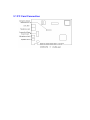
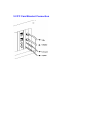
3.1 PC Card Connection
3.2 PC Card Bracket Connection
4.1 Checking Your Components
Unpack your fax/modem and make sure you have the following items:
•
•
•
•
The fax/modem.
A modular telephone cable to connect your fax/modem to the telephone line.
Communication software.
Two cables link JP1 and JP2 to sound card and mother board
When you open your package, make sure all of the above items are included and not damaged. If
you see that any components are damaged, please notify your dealer immediately.
4.2 What Else You Need
To complete your data communication system, you will need the following items:
Other communication software, if needed.
An active telephone line and telephone set (if you need to use a telephone with your modem).
An available PCI slot in the personal computer.
For voice function, a microphone and a speaker for voice recording and playing.
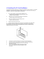
4.3 Installing The PC Card Fax/Modem
The following instructions explain how to install the fax/modem into a PC computer. If you will be
installing the fax/modem into a different computer, refer to the manual that came with your
computer or contact your computer dealer for instructions.
1.
Turn off the computer. No power must be applied to your
computer when you install the internal fax/modem, or the
computer could be damaged.
2.
Make sure you can freely access the back of the personal
computer. Remove the computer cover.
3.
Select any available PCI slot into which you can
install the internal fax/modem.
4.
Unscrew and remove the slot cover.
5.
Hold the internal fax/modem above the slot you have selected, and carefully slide
the fax/modem into the slot, applying even pressure to both ends of the fax/modem.
Stop inserting the fax/modem when its gold-plated edge connector is aligned and fully
seated into the base of the computer.
6.
7.
8.
9.
Connect the sound card cable with JP1 and the sound card.(Optional)
Connect the wake up ring cable with JP2 and the mother board.(Optional)
Use the screw that was holding the slot cover to secure the
fax/modem in the slot.
Use the cover-mounting screws to secure the computer
cover. This completes the hardware installation of your
fax/modem.
4.4 Connecting To The Telephone Line
Use the following procedure to connect your fax/modem to the telephone line:
1. Locate an available RJ-11 modular jack telephone outlet.
2. Take one end of the modular cord supplied with the fax/modem and plug it into the
LINE modular jack on the back of the fax/modem.
3. Plug the other end of the modular cord into the modular jack on the wall outlet, as you
would any modular telephone.
4.5 Connecting To Your Telephone Set
Your fax/modem also conveniently provides a second modular jack that lets you connect your
telephone to the same telephone line that the fax/modem is using. This lets you manually dial
data calls or make voice calls when you are not using your fax/modem. Also if you do not have
speaker phone and microphone, handset of telephone set can function as an input/output device
for voice to verify the connection.
Use the following procedure to connect your telephone to your fax/modem:
1. Connect the telephone's modular cord into the PHONE jack
on the back of your fax/modem.
2. Lift your telephone's handset and listen for a dial tone.
4.6 Verifying Your Connection
Start a communication program and place the computer into terminal mode. Refer to your
computer manual to find out the appropriate command to do so.
Then use the following procedure to verify your installation:
1.
Type
AT[Enter]
If your system is operating properly, your fax/modem sends an OK response to your screen and
waits for your next command.
2.
Use your communication software to prepare your
computer to dial a call. Then type
ATDx phone number[Enter]
where x is equal to T for touch-tone or P for pulse
dialing. The phone number is your telephone number.
For example, if your fax/modem is connected to the telephone
line 555-2121 and touch-tone dialing is supported in your area,
type
ATDT 5552121[Enter].
3.
You should hear the busy signal and receive a BUSY
response because the fax/modem is calling itself.
4.7 Connecting Microphone And Speaker
You could either use a handset connected to the fax/modem, or connect a microphone and a
speaker for voice recording and playback, or connect cable of Jumper 1 with sound card in your
PC (optional, refer to sound card user's guide). Also, you may enable the ring wake up function
by connecting the cable of Jumper 5 to motherboard. (the function is optional, see the PC user's
manual for more detail)
NOTE:
Any commercially available microphone is usable.
For the speaker, any 8 ohm speaker rated around 1Watt can
be driven directly by the audio output. An amplifier is
required if you need a higher output volume.
1.
2.
Connect the microphone to the mini-phone jack marked MIC.
Connect the speaker to the mini-phone jack marked SPK.
NOTE:
Take care of the pin setting and cable setting direction (JP1 and JP2) for your Fax/Modem
card, Sound card and Motherboard.
4.8 Voice Function Alternatives
1. AOpen Sound Card (recommanded)
Simply connect the cable from modem to AOpen Sound Card. User can get all the voice
function including message playing and recording through sound cards.
2. SpeakerPhone and MicroPhone
Connect SpeakerPhone and MicroPhone to modem. User can also get voice performance.
NOTE:
Any commercially available microphone is usable.
For the speaker, any 8 ohm speaker rated around 1 Watt can
be driven directly by the audio output. An amplifier is
required if you need a higher output volume.
4.9 Configuring Internal Modem With
Windows95/98/2000/NT
Windows 95:
1.
2.
3.
4.
5.
6.
Complete the installation referred to section 4.3.
Restart the computer after plugging in the modem. When Windows detects the modem, the
message "This wizard will complete the installation of: PCI Serial Controller" is displayed.
Click Next, then Other location, then enter the path to the drivers, then click OK.
Windows display "Windows found the following updated driver for this device: AOpen PCI
Modem Enumerator".
Click Finish and Windows displays "Please insert the disk labeled 'WIN95 installation Disk',
and then click OK.
Click OK and enter the path of the drivers again. Installation should then complete
automatically.
After completing the installation, you can check if the fax/modem was properly installed by using
the following procedure:
1.
2.
3.
4.
From My Computer, double click Control Panel.
Double click Modems.
Select Diagnostics tab.
Choose the COM port where the newly installed modem device is. Click More Info If the
Command and Response box displays results from ATI1 to AT+FCLA..., it indicates that your
fax/modem is set up properly.
Windows 2000:
1. Start computer after plugging in the modem. Windows will detect the modem.
2. Then the message “Welcome to the Found New Hardware Wizard” is displayed.
Click Next.
3. When Windows display “This wizard will complete the installation for this device:
PCI Simple communications controller”, choose “Search for a suitable driver for
my device”, then click Next.
4. When Windows display” Search for driver files for the following hardware device:
PCI Simple communications controller”, choose “Specify a location”, then click
Next.
5. In order to copy manufacturer’s files, click Browse.
6. Choose the correct path: D:\Drivers\Win2K\FM56-SM.( D is your CD-ROM.)
Then click OK.
7. Then the message will show the path you chose. Click Next.
8. If you want to continue installation, click Yes.
9. Windows has finished installation. Click Finish.
After completing the installation, you can check if the fax/modem was properly
installed by using the following procedure:
1.
2.
3.
4.
From My Computer, double click Control Panel.
Double click Modems.
Select Diagnostics tab.
Choose the COM port where the newly installed modem device is. Click on
More Info If the Command and Response box displays results from ATI1 to
AT+FCLA..., it indicates that your fax/modem is set up properly.
Windows NT4.0:
1. Explorer the driver files on your CD.
D:\Drivers\WinNT\FM56-SM
2. If you are using the WINACPCI driver already stop it using the steps in the following list.
a)
b)
c)
d)
e)
f)
g)
h)
Stop any programs (e.g., HyperTerm) that are using the modem driver
Click on Start, then Settings, then Control Panel.
Start the Devices applet
Scroll down to WinAcPci and highlight it
If the display says "running", continue with the next step. If not,
you are done.
Press the STOP button and say "yes", you do want to stop the driver.
Wait until the driver stops (there should be a "wait" dialog to watch)
Where the applet said the driver was "running" should now be blank
3. Start SETUP.EXE with a double click or by highlighting the file and pressing the ENTER key.
You should see a welcome screen. Click on the NEXT button.
4. You should see "AOpen FM56-PM(SM) Data Fax Speakerphone PCI Modem" in the display
window. Highlight it by clicking on the text. Click on the NEXT button to install the driver.
5. You should see a few copy operations and hear a small flurry of disk activity, and you should
see the next screen which says "the following drivers were installed successfully."
6. The driver is now installed and running. Note that you do not have to re-boot your system to
use the driver. You may exit the installation procedure and start HyperTerm to use the driver
on COM3 right now.
7. To continue the installation procedure to create the registry entries for the modem, perform
the steps in the following list.
a)
Click the check box titled, "Setup modem for the installed devices", and press the
FINISH button. You are now in the domain of the standard
Windows NT modem installer. If you have previously installed the NT modem, you will
see a listbox showing the installed modems on your system.
b)
If you are using the HCF modem already, remove it by clicking on it in the listbox and
pressing the REMOVE button. When the modem is gone, press the ADD button to
continue installing this version of the HCF modem.
8. There are two ways to finish the installation. The first way is to ask the installer to detect the
HCF modem. The second way is to select the HCF modem from the list using the "have disk"
feature.
9. To ask the installer to detect the modem, clear the "Don't detect my modem..." check box and
press the NEXT button. Windows NT will query every com port and find every modem
attached to your system. When it gets to COM3, it will detect a "standard modem". Click the
CHANGE button and prepare to select the modem INF file.
10. To select the modem from a list, check the "Don't detect my modem..." check box and press
the NEXT button. After a moment, NT will show the list. Press the HAVE DISK button to
select the HCF modem INF file.
11. At the "Install From Disk" dialog, enter the directory path where you loaded the installation
files. Select the modem from the list box and click the OK button. This will return you to the
"Install new modem" dialog. Press the NEXT button to install the modem files.
12. Check the "Selected Ports" button and highlight COM3. Press the Next button.
13. You are done. Click the FINISH button and start using the modem.
4.10 Tips On Configuring Your Communication Software
Your fax/modem uses the most up-to-date industry and commercially popular standards to
ensure functional compatibility with most communication software. During initial set-up of the
communication software, it will normally prompt you to define the type of fax/modem you are
using. Following is a general guideline to the device type you should choose.
NOTE:
The device type only defines the protocol by which your software will communicate with
your fax/modem and does not set nor limit the speed.
1.
2.
3.
4.
5.
6.
For the baud rate. choose any speed between 38,400 to 115,200.Your fax/modem will
automatically adjust to the best transmission speed after successfully connecting with a
remote fax/modem.
Many communication software uses the modem response (see Ch 7) to control program
flow. Make sure that the software is set to recognize a CONNECT 115200 response. If this
does not work, set the program to simply recognize just the CONNECT response without any
baud rate information.
There are three flow control mode: none, hardware (CTS/RTS) or software (XON/XOFF). Set
your software to use either hardware or software flow control. If set to none, the
communication software will not be able to detect a buffer overflow and result in transmission
errors.
For fax device type, choose 'TR29 Class 1'.
For fax speed, choose 'automatic' or 'fastest speed'. Your fax/modem will automatically adjust
to be best transmission speed after successfully connecting with a remote fax machine or
another fax/modem.
Make sure that you have correctly set all the other parameters required by the soft ware to
operate successfully. Refer to the manual that came with your communication software for
details.
You are now ready to do fax/modem communication !
4.11 Tips On Configuring SVD (Option)
Add "-SMS=2" to the modem string in communication progams to enable the SVD function. For
complete SVD commands, please refer to the AT command file on the driver disk.
5. Executing Commands
If you will be using a communication software program to make data calls, you will probably not
need to type commands, because your software program will handle these tasks for you.
Similarly, you will probably not see the responses because your software program may intercept
them. However, if you perform data activities directly with your fax/modem, you will find the
format for typing fax/modem commands and fax/ modem response helpful.
Using commands, you can have your fax/modem perform a variety of activities, such as dialing or
answering a data call or sending a fax. In order to send commands to your fax/modem, you
must access the modem in a terminal mode which is provided by most communication software.
To enter a command line, type:
ATccpp[Enter]
where AT must precede every command line (except when
you type the A/ command).
cc
pp
any of the commands available, described in
succeeding sections.
any parameters that is required by the command.
If you make a mistake while typing a command, press the Backspace key to delete the error.
To make a command line easy to read, you can insert spaces parentheses, hyphens, and other
punctuation in your command line. For example:
AT M3 DT 9, 1(818)555-1234
Your fax/modem ignores spaces and punctuation marks when executing a command line, but
these characters apply to the 40 characters limit.
A command line can contain up to 39 characters. If you want to type more than 39 characters on
a command line, type a regular command line (up to 39 characters long) and end it with a
semicolon as the last character. When you press Enter, your fax/modem executes the commands
and returns to command mode, so you can type your next command line.
For your convenience, the last command line you execute remains stored in the modem's
memory until you type a new command line and press the Enter key. If you want to re-execute
the last command, type
A/
The A/ command need not be prefixed by the 'AT' characters or ended with the [Enter] key.
NOTE:
The fax/modem command and response set are described in the text file, AT_CMD.TXT, in the
fax/modem Windows95 driver diskette. You can use DOS EDIT or any suitable editor to view this
file.
If a command requires a parameter such as 0 and 1, the parameter is identified as n in the left
column and described in the right column of the AT_CMD.TXT file.
IMPORTANT:
Each command, except for '+++' and 'A/', must be preceded by 'AT' and executed when you
press the [Enter] key. To review the format used to send fax/modem commands, refer to Section
of this manual.
6. S-Registers
Your fax/modem has S-registers that affect various operating characteristics. The registers let
you obtain information about the fax/modem, and let you test the fax/modem. Each S-Register
has a factory-set value, which you can read or change to fit your particular requirements. A
complete list of S-Register is provided in the COMMAND.TXT file on the driver diskette.
6.1 Reading An S-Register Value
6.2 Changing An S-Register Value
6.1 Reading An S-Register Value
1. To read the current value of an S-Register, type:
ATSr?[Enter]
where
r is an S-Register number.
The fax/modem responds with decimal value of the
S-Register, in three-digit format, followed by OK.
2.
To read values from more than one S-Register, type:
ATSr?Sr?[Enter]
where
r specify the different S-Register numbers.
For example, to read the value of Register S0 (number of
rings before answering) and S1 (incoming ring count),
type:
ATS0?S1?[Enter]
6.2 Changing An S-Register Value
To change an S-Register value, type
ATSr=n[Enter]
where r is the S-register number.
n is the value you want to assign to that S-register.
7. Specification
MODEM OPERATION
Line Rate
0.3, 1.2, 2.4, 4.8, 7.2, 9.6, 12, 14.4, 16.8, 19.2, 21.6, 24, 26.4, 28.8,
31.2, 33.6, 56 Kbps
DTE Rate
Operation
Linking
Flow Control
Compatibility
115200 bps maximum
Half or full-duplex over 2-wire dial-up line, asynchronous
Auto dial/answer, auto bauding, MNP10 auto fall-back/forward
RTS/CTS, XON/XOFF (software selectable)
Bell 103; 212A, ITU-T V.21; V.22; V.23; V.22bis; V.32; V.32bis; V.34;
V.90; K56flex (56K model only)
ITU-T V.42, MNP4 (auto-match)
ITU-T V.42bis, MNP5 (auto-match)
-36 dBm
Hayes AT and Escape sequence
1 configuration profiles
Power on self-test, V.54 loop test
Error Correction
Data Compression
Receive Sensitivity
Command Set
Memory
Diagnostics
FAX OPERATION
Speed
Compatibility
Command Set
14400 bps
Group 3 with T.30 protocol over ITU-T V.17; V.21 ch2; V.27ter; V.29
TR-29 Class 1
VOICE OPERATION
Operation
PVS
Sampling Rate
Telephone answering machine (TAM), voice mail system,
Simultaneuos Voice and Data (SVD), Optional
7.2 Khz using 2, 3 or 4 bits ADPCM; 11.025Khz linear PCM
GENERAL
Line Interface
Voice Interface
Ambient Temp.
Relative Humidity
2 x RJ-11 for line and telephone
2 x mini phone jack for microphone input and audio output
0 to 50
10 to 95% non-condensing
Dimensions
1.6w x 10.7h x 13.0d cm
A.1 FCC Notice
This equipment has been tested and found to comply with the limits for a Class B digital device,
pursuant to Part 15 of FCC Rules. These limits are designed to provide reasonable protection
against harmful interference in a residential installation. This equipment generates, uses and can
radiate radio frequency energy and, if not installed and used in accordance with the instructions,
may cause harmful interference to radio communications. However, there is no guarantee that
interference will not occur in a particular installation. If this equipment does cause harmful
interference to radio or television reception, which can be determined by turning the equipment
off and on, the user is encouraged to try to correct the interference by one or more of the
following measures:
• Reorient of relocate the receiving antenna.
• Increase the separation between the equipment and receiver.
• Connect the equipment into an outlet on a circuit different from that to which the receiver is
connected.
• Consult the dealer or an experienced radio / TV technician for help.
This unit was tested with shielded cables on the peripheral devices. Shielded cables must be
used with the unit to insure compliance. This statement can be deleted if unit was not tested with
shielded cables.
The manufacture is not responsible for any radio or TV interference caused by unauthorized
modifications to this equipment. Such modifications could void the user's authority to operate the
equipment.
This device complies with Part 15 of the FCC rules. Operation is subject to the following two
conditions:
1. This device may not cause harmful interference.
2. This device must accept any interference that may cause undesired operation.
A.2 FCC Requirement
This equipment complies with Part 68 of the FCC Rules. On the base unit of this equipment is a
label that contains, among other information, the FCC Registration Number and Ringer
Equivalence Number (REN) for this equipment. If requested, this information must be given to
telephone company.
The REN is useful in determining the quantity of devices you may connect to your telephone line
and still have all of those devices ring when your telephone number is called. In most, but not all
area, the sum of the REN's of all devices connected to one line should not exceed five (5). To be
certain of the number of devices you may connect to your line, as determined by the REN, you
should contact your local telephone company to determine the maximum REN for your calling
area.
If your equipment causes harm to the telephone network, the telephone company may
discontinue your service temporarily. If possible, they will notify you in advance. But if advance
notice is not practical, you will be notified as soon as possible. You will be informed of your right
to file a complain with the FCC. Your telephone company may make changes in its facilities,
equipments, operations or procedures that could affect the proper
functioning of your equipment. If they do, you will be notified in advance to give you an
opportunity to maintain uninterrupted telephone service.
The equipment may not be used on coin service by the telephone company. Connection to party
lines is subject to state tariffs.
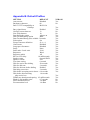
Appendix B: Default Profiles
SETTING
DEFAULT
Auto-answer
Disabled
Backspace character
08
Bell / CCITT compatibility at
Bell 212A
1200 bps
Busy signal detect
Enabled
Carriage return character
13
Line feed character
10
Data Set Ready option
Always on
Data Terminal Ready option
&D2
Data Terminal Ready pulse width 0.5 seconds
Echo option
On
Escape character definition
43 (+++)
Guard tones
Disabled
Long space disconnect
Disabled
Parity
None
Pulse make / break ratio
39/61
Responses
Word
Response enable
All
RTS-to-CTS delay
10 milliseconds
Speaker status
On until DCD
Speaker volume
Low
Test timer setting
0 second
Wait for carrier after dialing
50 seconds
Wait for dial tone
2 seconds
Wait for dial tone before dialing
Enabled
Dial delay pause time
2 seconds
Wait before accepting carrier detect 0.6 seconds
Wait before disconnecting
1.4 seconds
after carrier loss
DTMF tone duration and spacing 95 milliseconds
Flash (!) dial modifier time
0.7 seconds
PSTN attenuation level
-10 dBm
Fax attenuation level
-10 dBm
NVRAM
Yes
No
Yes
Yes
No
No
Yes
Yes
Yes
Yes
Yes
Yes
Yes
Yes
Yes
Yes
Yes
Yes
Yes
Yes
Yes
Yes
No
Yes
Yes
Yes
Yes
Yes
No
No
No
1. INTRODUCTION
1.1 OVERVIEW
This manual describes the host command and responses for the following Rockwell
modem families:
RC144HCF for ISA Bus Modem Device Set
RC144HCF-for PCI Bus Modem Device Set
RC144HCF-for PC Card Modem Device Set.
Refer to Modem Designer's Guides and Modem Software Release notes for commands
specific to a product model.
The commands and responses are implemented in host software for specific modem
models. The support for a command category is identified by modem model in the
Modem Designer's Guide. Additional configuration and implementation information is
available in release notes and/or readme files that accompany product software release.
The Product Configuration File contains exact application unique information and default
values.
1.2 Command Descriptions
These commands are grouped into the following categories:
Syntax and procedures Section 2
Data/fax commands Section 3
Fax commands Section 4
Voice commands Section 5
ISDN commands Section 6
Command Set Summary Section 7
1.3 REFERENCE DOCUMENTATION
Rockwell Document Order No. 1123, RC144HCF for ISA Bus Modem Designer's Guide
Rockwell Document Order No. 1129, RC144HCF for PCI Bus Modem Designer's Guide
Rockwell Document Order No. 1130, RC144HCF for PC Card Modem Designer's Guide
Document TD/ - E, STUDY GROUP 14, 19-27 March 1996, ITU-T, Revisions to V.25ter
Document TD/ - E, STUDY GROUP 14, 19-27 March 1996, ITU-T, Clean Draft Annex
A/V.25ter
ITU-T Recommendation T.31 (08/94), Terminals for Telematics Services, Asynchronous
Facsimile DCE Control -Service Class 1
ITU-T Recommendation T.31 Amendment 1(07/96), Terminals for Telematics Services,
Asynchronous Facsimile DCE Control - Service Class 1, Annex B - Procedure for
Service Class 1 Support of V.34 Modems TIA Standards Proposal No. SP-3131A Draft
Revision 5, Proposed New Standard "Voice Control Standard for Asynchronous DCE" (if
approved to be published as TIA/EIA-695)
2. SYNTAX AND PROCEDURES
The command and response syntax and procedures generally conform to referenced
recommendations and standards.
Since these recommendations and standards describe characteristics universal to a
large installed base of modems to a maximum degree, there may be syntax and
procedural differences due to extensions and behavioral differences in implemented
commands, parameters, and responses beyond that described in these
recommendations and standards.
The syntax and procedures described in this section are based on V.25ter with
additional information included for implemented extensions and behavioral differences
beyond V.25ter.
2.1 Alphabet
The
T.50 International Alphabet 5 (IA5) is used in this document. Only the low-order
seven bits of each character are significant to the modem; any eighth or higher-order
bit(s), if present, are ignored for the purpose of identifying commands and parameters.
Lower-case characters are considered identical to their upper-case equivalents when
received by the modem from the DTE. Result codes from the modem are in upper case.
2.2 DTE Commands Lines
Words enclosed in <angle brackets> are references to syntactical elements. The
brackets are not used when the words appear in a command line, the brackets are not
used. Words enclosed in [square brackets] represent optional items which may be
omitted from the command line at the specified point. The square brackets are not used
when the words appear in the command line. Other characters that appear in syntax
descriptions must as included as shown.
Any modem responses are mentioned in terms of their alphabetic format; the actual
response issued will depend on the setting of parameters that affect response formats,
e.g., Q and V commands (see 2.7).
2.2.1 Command Line General Format
is made up of three elements: the prefix, the body, and the termination
character.
The command line prefix consists of the characters "AT" or "at" or, to repeat the
execution of the previous command line, the characters "A/" or "a/".
The body is made up of individual commands described in this document. Space
characters (IA5 2/0) are ignored and may be used freely for formatting purposes, unless
they are embedded in numeric or string constants. The termination character may not
appear in the body. The modem can accept at least 40 characters in the body.
The termination character may be selected by a user option (parameter S3), the default
being CR.
A command line
2.2.2 Command Line Editing
The character defined by parameter S5 (default, BS) is interpreted as a request from the
DTE to the modem to delete the previous character. Any control characters (IA5 0/0
through 1/15, inclusive) that remain in the command line after receipt of the termination
character are ignored by the modem.
The modem checks characters from the DTE first to see if they match the termination
character (S3), then the editing character (S5), before checking for other characters.
This ensures that these characters will be properly recognized even if they are set to
values that the modem uses for other purposes. If S3 and S5 are set to the same value,
a matching character will be treated as matching S3 (S3 is checked before S5).
2.2.3 Command Line Echo
The modem may echo characters received from the DTE during command state and
online command state back to the DTE, depending on the setting of the E command. If
so enabled, characters received from the DTE are echoed in the same format as
received. Invalid characters in the command line or incomplete or improperly-formed
command line prefixes may not be echoed.
2.2.4 Repeating a Command Line
If the prefix "A/" or "a/" is received, the modem immediately executes once again the
body of the preceding command line.
No editing is possible, and no termination character is necessary. A command line may
be repeated multiple times in this manner. Responses to the repeated command line are
issued using format of the original command line. If "A/" is received before any command
line has been executed, the preceding command line is assumed to have been empty
(that results in an OK result code).
2.2.5 Types of DTE Commands
There are two types of commands: action commands and parameter commands.
Commands of either type may be included in command lines, in any order.
Action commands may be "executed" (to invoke a particular function of the equipment,
which generally involves more than the simple storage of a value for later use), or
"tested" (to determine whether or not the equipment implements the action command,
and, if subparameters are associated with the action, the ranges of subparameter values
that are supported).
Parameters may be "set" (to store a value or values for later use), "read" (to determine
the current value or values stored), or "tested" (to determine whether or not the
equipment implements the parameter, and the ranges of values supported).
2.3 Basic Syntax Commands
2.3.1 Basic syntax command format
The format of Basic Syntax commands, except for the D and S commands, is as follows:
<command>[<number>]
where <command> is either a single character, or the "&" character followed by a single
character per V.25 ter. In addition, <command> can be the "%" character followed by a
single character, the "*" character followed by a single character, or the "^" character
followed by a single character.
<number> may be a string of one or more characters from "0" through "9" representing a
decimal integer value. Commands that expect a <number> are noted in the description
of the command. If a command expects <number> and it is missing (<command> is
immediately followed in the command line by another <command> or the termination
character), the value "0" is assumed. If a command does not expect a <number> and a
number is present, an ERROR is generated. All leading "0"s in <number> are ignored by
the modem.
Additional commands may follow a command (and associated parameter, if any) on the
same command line without any character required for separation. The actions of some
commands cause the remainder of the command line to be ignored (e.g., A).
See the D command for details on the format of the information that follows it.
2.3.2 S-Parameters
Commands that begin with the letter "S" are known as "S-parameters". The number
following the "S" indicates the "parameter number" being referenced. If the number is not
recognized as a valid parameter number, an ERROR result code is issued.
Immediately following this number, either a "?" or "=" character must appear. "?" is used
to read the current value of the indicated S-parameter; "=" is used to set the S-parameter
to a new value.
S<parameter_number>?
S<parameter_number>=[<value>]
If the "=" is used, the new value to be stored in the S-parameter is specified in decimal
following the "=". If no value is given (i.e., the end of the command line occurs or the
next command follows immediately), the S-parameter specified may be set to 0, or an
ERROR result code issued and the stored value left unchanged. The ranges of
acceptable values are given in the description of each S-parameter.
If the "?" is used, the modem transmits a single line of information text to the DTE. The
text portion of this information text consists of exactly three characters, giving the value
of the S-parameter in decimal, with leading zeroes included.
2.4 Extended Syntax Commands
2.4.1 Command Naming Rules
Both actions and parameters have names, which are used in the related commands.
Names always begin with the character "+". Following the "+", from one to 16 additional
characters appear in the command name. These characters will be selected from the
following set:
A through Z (IA5 4/1 through 5/10)
0 through 9 (IA5 3/0 through 3/9)
! (IA5 2/1)
% (IA5 2/5)
- (IA5 2/13)
. (IA5 2/14)
/ (IA5 2/15)
: (IA5 3/10)
_ (IA5 5/15)
The first character following the "+" must be an alphabetic character in the range of "A"
through "Z". This first character generally implies the application in which a command is
used (e.g., F for Fax or V for voice).
The modem considers lower-case characters to be the same as their upper-case
equivalents.
2.4.2 Values
When subparameters are associated with the execution of an action, or when setting a
parameter, the command may include specification of values. This is indicated by the
appearance of <value> in the descriptions below.
<value> consists of either a numeric constant or a string constant.
2.4.2.1 Numeric Constants
Numeric constants are expressed in decimal, hexadecimal, or binary.
Decimal numeric constants consist of a sequence of one or more of the characters "0"
through "9", inclusive. Hexadecimal numeric constants consist of a sequence of one or
more of the characters "0" through "9", inclusive, and "A" through "F" inclusive. The
characters "A" through "F" represent the equivalent decimal values 10 through 15.
Binary numeric constants consist of a sequence of one or more of the characters "0" and
"1".
In all numeric constants, the most significant digit is specified first. Leading "0"
characters are ignored by the modem. No spaces, hyphens, periods, commas,
parentheses, or other generally-accepted numeric formatting characters are permitted in
numeric constants; note in particular that no "H" suffix is appended to the end of
hexadecimal constants.
2.4.2.2 String Constants
String constants consist of a sequence of displayable IA5 characters, each in the range
from 2/0 to 7/15, inclusive, except for the characters '"' (IA5 2/2) and "\" (IA5 5/12). String
constants are bounded at the beginning and end by the double-quote character ('"', IA5
2/2).
Any character value may be included in the string by representing it as a backslash ("\")
character followed by two hexadecimal digits. For example, "\0D" is a string consisting of
the single character <CR> (IA5 0/13). If the "\" character itself is to be represented in a
string, it is encoded as "\5C". The double-quote character, used as the beginning and
ending string delimiter, is represented within a string constant as "\22".
A "null" string constant, or a string constant of zero length, is represented by two
adjacent delimiters ("").
2.4.2.3 Compound Values
Actions may have more than one subparameter associated with them, and parameters
may have more than one value.
These are known as "compound values", and their treatment is the same in both actions
and parameters. A compound value consists of any combination of numeric and string
values (as defined in the description of the action or parameter). The comma character
must be included as a separator, before the second and all subsequent values in the
compound value. If a value is not specified (i.e., defaults assumed), the required comma
separator must be specified; however, trailing comma characters may be omitted if all
associated values are also omitted.
2.4.3 Action commands
2.4.3.1 Action execution command syntax
There are two general types of action commands: those that have associated
subparameter values that affect only that invocation of the command, and those that
have no subparameters. If subparameters are associated with a command, the definition
of the action command indicates, for each subparameter, whether the specification of a
value for that subparameter is mandatory or optional. For optional subparameters, the
definition indicates the assumed (default) value for the subparameter if no value is
specified for that subparameter; the assumed value may be either a previous value (i.e.,
the value of an omitted subparameter remains the same as the previous invocation of
the same command, or is determined by a separate parameter or other mechanism), or
a fixed value (e.g., the value of an omitted subparameter is assumed to be zero).
Generally, the default value for numeric subparameters is 0, and the default value for
string subparameters is "" (empty string).
The following syntax is used for actions that have no subparameters:
+<name>
The following syntax is used for actions that have one subparameter:
+<name>[=<value>]
The following syntax is used for actions that have two or more subparameters:
+<name>[=<compound_value>]
For actions that accept subparameters, if all subparameters are defined as being
optional, and the default values for all subparameters are satisfactory, the data terminal
equipment (DTE) may use the first syntax above (i.e., omit the "=" from the action
execution command as well as all of the subparameter value string).
If all other relevant criteria are met (e.g., the modem is in the proper state), the
command is executed with any indicated subparameters. If <name> is not recognized,
the modem issues the ERROR result code and terminates processing of the command
line. An ERROR is also generated if a subparameter is specified for an action that does
not accept subparameters, if too many subparameters are specified, if a mandatory
subparameter is not specified, if a value is specified of the wrong type, or if a value is
specified that is not within the supported range.
2.4.3.2 Action Test Command Syntax
The DTE may test if an action command is implemented in the modem by using the
syntax:
+<name>=?
If the modem does not recognize the indicated name, it returns an ERROR result code
and terminates processing of the command line. If the modem does recognize the action
name, it returns an OK result code. If the named action accepts one or more
subparameters, the modem sends an information text response to the DTE, prior to the
OK result code, specifying the values supported by the modem for each such
subparameter, and possibly additional information. The format of this information text is
defined for each action command.
2.4.4 Parameter Commands
2.4.4.1 Parameter Types
Parameters may be defined as "read-only" or "read-write". "Read-only" parameters are
used to provide status or identifying information to the DTE, but cannot be set by the
DTE; attempting to set their value is an error. In some cases (specified in the description
of the individual parameter), the modem may ignore attempts to set the value of such
parameters rather than respond with an ERROR result code, if the continued correct
operation of the interface between the modem and DTE will not be affected by such
action. Read-only parameters may be read and tested.
"Read-write" parameters may be set by the DTE, to store a value or values for later use.
Read-write parameters may be set, read, and tested.
Parameters may take either a single value, or multiple (compound) values. Each value
may be either numeric or string; the definition of the parameter will specify the type of
value for each subparameter. Attempting to store a string value in a numeric parameter,
or a numeric value in a string parameter, is an error.
2.4.4.2 Parameter Set Command Syntax
The definition of the parameter indicates, for each value, whether the specification of
that value is mandatory or optional. For optional values, the definition indicates the
assumed (default) value if none is specified; the assumed value may be either a
previous value (i.e., the value of an omitted subparameter retains its previous value), or
a fixed value (e.g., the value of an omitted subparameter is assumed to be zero).
Generally, the default value for numeric parameters is 0, and the default value for string
parameters is "" (empty string).
The following syntax is used for parameters that accept a single value:
+<name>=[<value>]
The following syntax is used for parameters that accept more than one value:
+<name>=[<compound_value>]
For each implemented parameter, if all mandatory values are specified, and all values
are valid according to the definition of the parameter, the specified values are stored. If
<name> is not recognized, one or more mandatory values are omitted, or one or more
values are of the wrong type or outside the permitted range, the modem issues the
ERROR result code and terminates processing of the command line. An ERROR is also
generated if too many values are specified. In case of an
error, all previous values of the parameter are unaffected.
2.4.4.3 Parameter Read Command Syntax
DTE may determine the current value or values stored in a parameter by using the
following syntax:
+<name>?
The modem responds by sending the current values stored for the parameter to the DTE
in an information text response.
The format of this response is described in the definition of the parameter. Generally, the
values are sent in the same form in which they would be issued by the DTE in a
parameter setting command; if multiple values are supported, they will generally be
separated by commas, as in a parameter setting command.
The
2.4.4.4 Parameter test command syntax
The DTE may test if a parameter is implemented in the modem, and determine the
supported values, by using the syntax:
+<name>=?
If the modem does not recognize the indicated name, it returns an ERROR result code
and terminates processing of the command line. If the modem does recognize the
parameter name, it returns an information text response to the DTE, followed by an OK
result code. The information text response indicates the values supported by the modem
for each such subparameter, and possibly additional information. The format of this
information text is defined for each parameter.
2.4.5 Additional Syntax Rules
2.4.5.1 Concatenating Commands after Extended Syntax Commands
Additional commands may follow an extended-syntax command on the same command
line if a semicolon (";") is inserted after the preceding extended command as a separator.
The semicolon is not necessary when the extended syntax command is the last
command on the command line.
2.4.5.2 Concatenating commands After Basic Format Commands
Extended syntax commands may appear on the same command line after a basic
syntax command without a separator, in the same manner as concatenation of basic
syntax commands.
2.5 Issuing Commands
All characters in a command line must be issued at the same data rate, and with the
same parity and format. ???
The modem will ignore any command line that is not properly terminated. The modem
may consider 30 seconds of mark idle time between any two characters as an
improperly terminated command line. In this case the modem may or may not generate
an ERROR message. The modem will ignore any characters received from the DTE that
are not part of a properly-formatted command line.
If the maximum number of characters that the modem can accept in the body is
exceeded, an ERROR result code is generated after the command line is terminated.
The DTE will not begin issuing a subsequent command line until at least one-tenth of a
second has elapsed after receipt of the entire result code issued by the modem in
response to the preceding command line.
2.6 Executing Commands
Upon receipt of the termination character, the modem commences execution of the
commands in the command line in the order received from the DTE. Should execution of
a command result in an error, or a character be not recognized as a valid command,
execution is terminated, the remainder of the command line is ignored, and the ERROR
result code is issued.
Otherwise, if all commands execute correctly, only the result code associated with the
last command is issued; result codes for preceding commands are suppressed. If no
commands appear in the command line, the OK result code is issued.
2.6.1 Aborting Commands
Some action commands that require time to execute may be aborted while in progress;
these are explicitly noted in the description of the command. Aborting of commands is
accomplished by the transmission from the DTE to the modem of any character. A single
character is sufficient to abort the command in progress; however, characters
transmitted during the first 125 milliseconds after transmission of the termination
character are ignored (to allow for the DTE to append additional
control characters such as line feed after the command line termination character). To
ensure that the aborting character is recognized by the modem, it should be sent at the
same rate as the preceding command line; the modem may ignore characters sent at
other rates. When such an aborting event is recognized by the modem, the modem
terminates the command in progress and returns an appropriate result code to the DTE,
as specified for the particular command.
2.6.2 Handling of Invalid Numbers and S-Parameter Values
The modem reacts to undefined numbers and S-parameter values in one of three ways:
1. Issue the ERROR result code, and leave the previous value of the parameter
unchanged;
2. Issue the OK result code, and leave the previous value of the parameter unchanged;
or,
3. Issue the OK result code, and set the parameter value to the valid value nearest to
that specified in the command line. The description of each command specifies which of
these three techniques is used to handle invalid parameter values for that command or
parameter.
2.7 Modem Responses
While in command state and online command state, the modem will issue responses
using the same rate, word length, and parity as the most recently received DTE
command line. In the event that no DTE command has yet been received, rate, word
length, and parity used will depend on the capabilities of the modem. When the modem
transitions from the command state or online command state to the online data state, the
result code CONNECT should be issued at the bit rate and parity used during the
command state. When the modem transitions from the online data state to the command
state or online command state, the result codes should be issued at the bit rate used
during the online data state. Thereafter, any unsolicited result codes should use the bit
rate and parity of the last command line issued by the DTE to the modem. The
characters of a response will be contiguous, with no more than 100 milliseconds of mark
idle issued between characters in addition to stop elements
.
2.7.1 Responses
There are two types of responses that may be issued by the modem: information text
and result codes.
Information Text. Information text responses consist of three parts: a header, information
text, and a trailer:
1. The characters transmitted for the header are determined by the V command.
2. The trailer consists of two characters, being the character having the ordinal value of
parameter S3 followed by the character having the ordinal value of parameter S4.
3. Information text usually consists of a single line; information text returned in response
to some commands may contain multiple lines, and the text may therefore include CR,
LF, and other formatting characters to improve readability.
Result Code Parts. Result codes consist of three parts: a header, the result text, and a
trailer.
1. The characters transmitted for the header and trailer are determined by the V
command setting.
2. The result text may be transmitted as a number or as a string, also depending on a
the V command setting.
Result Code Types. There are three types of result codes: final, intermediate, and
unsolicited. Result codes are described in Section 3.3.
1. A final result code indicates the completion of a full modem action and a ability to
accept new commands from the DTE.
2. An intermediate result code is a report of the progress of an modem action. The
CONNECT result code is an intermediate result code. In the case of a dialing or
answering command, the modem switches from command state to online data state, and
issues a CONNECT result code. This is an intermediate result code for the modem
because it cannot accept commands from the DTE while in online data state. When the
modem switches back to the command state it then issues a final result code (such as
OK or NO CARRIER).
3. Unsolicited result codes (such as RING) indicate the occurrence of an event not
directly associated with the issuance of a command from the DTE.
2.7.2 Extended Syntax Result Codes
Extended syntax result codes may be issued in response to either basic or extended
commands, or both. The appropriate responses are specified in the definitions of the
commands, the responses, or both. The general format of extended syntax result codes
is the same as result codes defined in TIA-602 with regard to headers and trailers. The
characters specified in S-parameters S3 and S4 are used in headers and trailers of
extended syntax result codes as they are in basic format result codes. The setting of the
V command affects the headers and trailers associated with extended syntax result
codes in the same manner as basic format result codes; however, unlike basic format
result codes, extended syntax result codes have no numeric equivalent, and are always
issued in alphabetic form.
Extended syntax result codes are subject to suppression by the Q1 command, as with
basic format result codes. The issuance of extended syntax result codes are not be
affected by the setting of the X command. Extended syntax result codes may be either
final, intermediate, or unsolicited; the type being indicated in the definition of the result
code.
Extended syntax result codes are prefixed by the "+" character to avoid duplication of
basic format result codes specified in TIA-602. Following the "+" character, the name of
the result code appears; result code names follow the same rules as command names.
Extended syntax result codes may include the reporting of values. The definition of the
result code specifies whether or not values are appended to the result code, and, if so,
how many, their types, and their assumed default values if omitted.
Data/voice Modes. When no values are to be reported, the result code appears in the
simplest form:
+<name>
If a single value is to be reported, the form of the result code is:
+<name>: <value>
Note that a single space character separates the colon character from the <value>; no
space appears between the result code name and the colon. If multiple values are to be
reported with the result code, the form is:
+<name>: <compound_value>
Fax Modes. If a single value is to be reported, the form of the result code is:
<value> or (<value>) Needs confirmation!!!!!!!!!
2.7.3 +<name>: <compound_value>Information Text Formats for Test
Commands
In general, the format of information text returned by extended syntax commands is
described in the definition of the command.
Note that the modem may insert intermediate <CR> characters in very long information
text responses, in order to avoid overrunning DTE receive buffers. If intermediate <CR>
characters are included, the modem does not include the character sequences "0
<CR>"or "OK<CR>", so that DTE can avoid false detection of the end of these
information text responses.
2.7.3.1 Range of Values
When the action accepts a single numeric subparameter, or the parameter accepts only
one numeric value, the set of supported values may be presented in the information text
as an ordered list of values. The list is preceded by a left parenthesis (() , and is followed
by a right parenthesis ()). If only a single value is supported, it appears between the
parentheses. If more than one value is supported, then the values may be listed
individually, separated by comma characters, or, when a continuous range of values is
supported, by the first value in the range, followed by a hyphen character (-), followed by
the last value in the range. The specification of single values and ranges of values may
be intermixed within a single information text. In all cases, the supported values is
indicated in ascending order.
For example, the following are some examples of value range indications:
(0) Only the value 0 is supported.
(1,2,3) The values 1, 2, and 3 are supported.
(1-3) The values 1 through 3 are supported.
(0,4,5,6,9,11,12) The several listed values are supported.
(0,4-6,9,11-12) An alternative expression of the above list.
2.7.3.2 Compound Range of Values
When the action accepts more than one subparameter, or the parameter accepts more
than one value, the set of supported values is presented as a list of the
parenthetically-enclosed value range strings described above, separated by commas.
For example, the information text in response to testing an action that accepts three
subparameters, and supports various ranges for each of them, could appear as follows:
(0),(1-3),(0,4-6,9,11-12)
This indicates that the first subparameter accepts only the value 0, the second accepts
any value from 1 through 3 inclusive, and the third subparameter accepts any of the
values 0, 4, 5, 6, 9, 11, or 12.
3.1 COMMAND GUIDELINES
The commands used to control and report modem operation in data modem mode are
defined in this section. The default values are typical of a fully configured modem
supporting all data rates and options. The actual default value is dependent upon
modem software as defined by the Product Configuration File. Commands will only be
accepted by the modem once the previous command has been fully executed, which is
normally indicated by the return of an appropriate result code. Execution of commands D
and A, either as a result of a direct command or a re-execute command, will be aborted
if another character is entered before completion of the handshake.
3.1.1 Escape Code Sequence
When the modem has established a connection and has entered on-line data mode, it is
possible to break into the data transmission in order to issue further commands to the
modem in an on-line command mode. This is achieved by the DTE sending to the
modem a sequence of three ASCII characters specified by register S2. The default
character is '+'. The maximum time allowed between receipt of the last character of the
three escape character sequence from the DTE and sending of the OK result code to the
DTE is controlled by the S12 register.
3.1.1.1 +FCLASS=0- Select Data Modem Mode
+FCLASS=0 selects the Data Modem Mode. The Data Modem Mode commands and
responses described in this section are applicable when command +FCLASS=0. (See
Section 3.2.1.2 for the definition of the FCLASS command.)
3.2 DATA COMMANDS
The modem will respond to the commands detailed below. Parameters applicable to
each command are listed with the command description. The defaults shown correspond
to default values provided in the Product Configuration File (PCF).
3.2.1 Generic Modem Control
3.2.1 Generic Modem Control
3.2.1.1 Z - Reset to Default Configuration
This command instructs the modem to reset to default values as altered by non-volatile
parameter storage. If the modem is connected to the line, it will be disconnected from
the line, terminating any call in progress. All of the functions of the command are
completed before the modem issues the result code. The DTE should not include
additional commands on the same command line after the Z command because such
commands are ignored.
Syntax
Z
Result Code
OK
3.2.1.2 +FCLASS - Select Active Service Class
This command selects the active service class (mode).
Syntax
+FCLASS=<mode>
Defined Values
<mode> Decimal number which corresponds to the selected service class.
Command options:
0 Select Data Mode (see Section 3). (Default.)
1 or 1.0 Select Facsimile Class 1.0 Mode (see Section 4)
8 Select Voice Mode (see Section 5)
80 Select VoiceView Mode (see Section 5)
Result Codes
OK For <mode> = 0, 1, 1.0, 8, and 80 as supported by the Product Configuration File.
ERROR Otherwise.
Reporting Current or Selected Values
Command: +FCLASS?
Response: +FCLASS: <mode>
Example: +FCLASS: 0 For the default setting.
Reporting Supported Range of Parameter Values
Command: +FCLASS=?
Response: +FCLASS: (<mode> range)
Example: +FCLASS: (0, 1,1.0,8, 80)
3.2.1.3 &F - Set to Factory-Defined Configuration
This command instructs the modem to set all parameters to factory default values
defined in the product Configuration Table
The modem loads the factory default configuration (profile). The factory defaults are
identified for each command and in the
S-Parameter descriptions. A configuration (profile) consists of a subset of S-Parameters.
Syntax
&F
Result Code
OK
3.2.1.4 I - Request Identification Information
This command causes the modem to report one or more lines of product information text
as provided by the Product Configuration File, as selected by the <value> subparameter,
followed by a final result code.
Syntax
I[<value>]
Defined Values
<value> Decimal number corresponding to the selected information.
0 <value> 0 report.
1 <value> 1 report.
2 <value> 2 report.
3 <value> 3 report.
4 <value> 4 report.
5 <value> 5 report.
6 <value> 6 report.
7 <value> 7 report.
Result Codes
OK <value> = 0 to 7.
ERROR Otherwise.
3.2.1.5 +GMI - Request Manufacturer Identification
This command causes the modem to report the modem product manufacturer as
provided by the Product Configuration File.
Syntax
+GMI
Response
ROCKWELL
OK
3.2.1.6 +GMM - Request Model Identification
This command causes the modem to report the modem product model as provided by
the Product Configuration File.
Syntax
+GMM
Typical Response
RC56HCF
OK
3.2.1.7 +GMR - Request Revision Identification
This command causes the modem to report the modem version, revision level or date as
provided by the Product Configuration File.
Syntax
+GMR
Typical Response
RC56HCF R6775 V2.0 5/29/97
OK
3.2.1.8 +GSN - Request Product Serial Number Identification
This command causes the modem to report the modem product model serial number as
provided by the Product
Configuration File.
Syntax
+GSN
Typical Response
VX.XXX-serial number
OK
3.2.1.9 +GOI - Request Global Object Identification
This command causes the modem to transmit one or more lines of information text
identifying the device, based on the ISO system for registering unique object identifiers.
Typically, the text consists of a single line containing numeric strings delimited by period
characters. The general format of object identifiers is defined in Section 28 of ITU-T
Recommendation X.208; the encoding rules are defined in ITU-T Recommendation
X.209.
Syntax
+GOI
Typical Response
TBD
OK
3.2.1.10 +GCAP - Request Complete Capabilities List
This extended-format command causes the modem to transmit one or more lines of
information text listing additional capabilities command +<name>s , which is intended to
permit the user to identify the overall capabilities of the modem. In particular, if the
modem implements a particular modem control standard that uses Extended Syntax
Commands, and if that modem control standard includes command(s) that indicate
general capabilities, the +<names>(s) of those commands will be reported to the modem
in response to a +GCAP command.
Syntax
+GCAP
Example Responses
+GCAP: +FCLASS, +MS, +ES, +DS, for a data modem that supports all capabilities
listed
Where:
+FCLASS T.class1, +F (Class 1 Facsimile modem Control)
+MS +M commands (Modulation Control: +MS and +MR commands)
+ES +E commands (Error Control: +ES, +EB, +ER, +EFCS, +ETBM)
+DS +D commands (Data Compression: +DS and +DR)
3.2.2 DTE-Modem Interface Commands
3.2.2 DTE-Modem interface commands
The parameters defined in this section control the operation of the interface between the
DTE and modem.
3.2.2.1 E - Command Echo
The modem enables or disables the echo of characters to the DTE according to the
parameter supplied.
Syntax
E[value>]
Defined Values
<value> Decimal number corresponding to the selected option.
0 Disables command echo.
1 Enables command echo. (Default.)
Result Codes
OK <value> = 0 or 1.
ERROR Otherwise.
3.2.2.2 Q - Quiet Results Codes Control
The command enables or disables the sending of result codes to the DTE according to
the parameter supplied. The parameter value, if valid, is written to S14 bit 2.
Syntax
O[value>]
Defined Values
<value> Decimal number corresponding to the selected option.
0 Enables result codes to the DTE. (Default.)
1 Disables result codes to the DTE.
Result Codes
OK <value> = 0 or 1.
ERROR Otherwise.
3.2.2.3 V - Result Code Form
This command selects the sending of short-form or long-form result codes to the DTE.
Syntax
V[value>]
Defined Values
<value> Decimal number corresponding to the selected option.
0 Enables short-form (terse) result codes. Line feed is not issued before a short-form
result code.
1 Enables long-form (verbose) result codes. (Default.)
Result Codes
OK <value> = 0 or 1.
ERROR Otherwise.
3.2.2.4 X - Extended Result Codes
This command selects which subset of the result messages will be used by the modem
to inform the DTE of the results of commands.
Blind dialing is enabled or disabled by country parameters. If the user wishes to enforce
dial tone detection, a "W" can be placed in the dial string (see D command). Note that
the information below is based upon the default implementation of the X results table.
Table 3-4 indicates the messages which are enabled for each X value.
If the modem is in facsimile mode (+FCLASS=1), the only message sent to indicate a
connection is CONNECT without a speed indication.
Syntax
X[<value>]
Defined Values
<value> Decimal number corresponding to the selected option.
0 CONNECT result code is given upon entering online data state. Dial tone and
busy detection are disabled.
1 CONNECT <text> result code is given upon entering online data state. Dial tone
and busy detection are disabled.
2 CONNECT <text> result code is given upon entering online data state. Dial tone
detection is enabled, and busy detection is disabled.
3 CONNECT <text> result code is given upon entering online data state. Dial tone
detection is disabled, and busy detection is enabled.
4 CONNECT <text> result code is given upon entering online data state. Dial tone
and busy detection are both enabled. (Default.)
Result Codes
OK <value> = 0 to 4.
ERROR Otherwise.
3.2.2.5 &C - RLSD Behavior
This parameter determines how the state of the Received Line Signal Detector (RLSD)
output relates to the detection of received line signal from the distant end. Changing the
parameter will take effect immediately in both the command and online command states.
In &C1 mode of operation, RLSD is not turned off until all data previously received from
the remote modem is delivered to the local DTE. However, such buffered data will be
discarded and RLSD will be turned off if the DTE turns off DTR (if &D1 or &D2 is set).
Syntax
&C[<value>] <value> = 0 or 1.
Defined Values
<value> Decimal number corresponding to the selected option.
0 RLSD is always ON.
1 RLSD follows the state of the carrier. (Default.)
Result Code
OK <value> = 0 or 1
ERROR Otherwise.
3.2.2.6 &D - DTR Behavior
This parameter determines how the modem responds when the Data Terminal Ready
(DTR) input is changed from the ON to the OFF condition during online data state.
Syntax
&D[<value>] <value> = 0 - 2.
Defined Values
<value> Decimal number corresponding to the selected option.
0 Modem ignores DTR.
1 Upon an on-to-off transition of DTR, the modem enters online command state and
issues an OK result code; the call remains connected.
2 Upon an on-to-off transition of DTR, the modem instructs the underlying modem
to perform an orderly cleardown of the call. The disposition of any data in the
modem pending transmission to the remote modem is controlled by the +ETBM
parameter; otherwise, this data is sent before the call is cleared, unless the
remote modem clears the call first (in which case pending data is discarded). The
modem disconnects from the line. Automatic answer is disabled while DTR
remains off.
Result Code
OK <value> = 0 or 2
ERROR Otherwise.
3.2.2.7 +IFC - DTE-Modem Local Flow Control
This extended-format compound parameter controls the operation of local flow control
between the DTE and the modem during the data state when V.42 error control is used,
or when fallback to non-error control mode is specified to include buffering and flow
control. It accepts two numeric subparameters.
Syntax
+IFC=[<modem_by_DTE>[,<DTE_by_modem>]]
Defined Values
<modem_by_DTE> Specifies the method to be used by the DTE to control the flow of
received data from the modem.
0 = None.
1 = XON/XOFF on transmitted data (XON/XOFF on transmit data); do not pass
XON/XOFF characters to the remote modem.
2 = Circuit 133 (Ready for Receiving). (Default.)
3 = XON/XOFF on transmitted data with XON/XOFF characters being passed through
to the remote modem in addition to being acted upon for local flow control.
<DTE_by_modem> Specifies the method to be used by the modem to control the flow of
transmitted data from the DTE.
0 = None.
1= XON/XOFF on received data.
2 = CTS/RTS. (Default.)
Reporting Current or Selected Values
Command: +IFC?
Response: +IFC: <modem_by_DTE>,<DTE_by_modem>
Example: +IFC: 2,2 for the defaults.
Reporting Supported Range of Parameter Values
Command: +IFC=?
Response: +IFC: (<modem_by_DTE> range),(<DTE_by_modem> range)
Example: +IFC: (0-3),(0-2)
3.2.2.8 +ILRR - DTE-Modem Local Rate Reporting
This extended-format numeric parameter controls whether or not the extended-format
+ILRR:<rate> information text is
transmitted from the modem to the DTE.
Syntax
+ILRR=<value>
Defined Values
<value> Decimal number corresponding to the selected option.
0 Disables reporting of local port rate (+ILRR: is not transmitted).
1 Enables reporting of local port rate (+ILRR: is transmitted).
Reporting Current or Selected Values
Command: +ILRR?
Response: +ILRR: <current value>
Example: +ILRR: 0 For the default setting
Reporting Supported Range of Parameter Values
Command: +ILRR=?
Response: +ILRR: (<value> range)
Example: +ILRR: (0,1)
Reported Rate
The <rate> reported represents the current (negotiated or renegotiated) DTE-modem
rate. If enabled, the intermediate result code is transmitted after any modulation, error
control or data compression reports are transmitted, and before any final result code
(e.g., CONNECT) is transmitted. The <rate> is applied after the final result code is
transmitted.
The DTE-modem port rate will change only if neither buffered mode nor error controlled
means are enabled (+ES=x,0) and if the negotiated carrier rate (+MRR) does not match
the current DTE-modem port rate (autodetected from the previous command line).
Syntax
+ILRR: <rate>[,<rx_rate>]
Defined Values
<rate> Decimal value representing the current (negotiated or renegotiated) DTE-modem
rate:
0, 300, 1200, 2400, 4800, 9600, 19200, 38400, 57600, or 115200
<rx_rate> Optional decimal value reporting the RXD rate, if it is different from the TXD
rate:
0, 300, 1200, 2400, 4800, 9600, 19200, 38400, 57600, or 115200
Example
+ILRR: 19200
3.2.2.9 +H - Enable/Disable Video Ready Mode
This command enables or disables Rockwell Video Ready Mode.
Syntax
+H[<value>]
Defined Values
<value> Decimal number corresponding to the selected option.
0 Disable video ready mode.
16 Enable video ready mode.
Result Codes
OK <value> = 0 or 16.
ERROR Otherwise.
3.2.3 Call Control
3.2.3.1 D - Dial
This command directs the modem to go on-line, dial according to the entered string and
attempt to establish a connection. If no dial string is supplied, the modem will go on-line
and attempt the handshake in originate mode. In W-class models, the action of going
off-hook is affected by the status of the Line Current Sense input, if line current sensing
is enabled, and by the blacklist and delayed list. NOTE: If the ATD command is issued
before the S1 register has cleared, the modem will respond with the NO CARRIER result
code.
If +FCLASS=0 is selected, the modem will behave as a data modem and will attempt to
connect to another data modem.
The modem will have up to the period of time specified by register S6 or S7 to wait for
carrier and complete the handshake.
If this time expires before the modem can complete the handshake, the modem will go
on-hook with the NO CARRIER response. This command will be aborted upon receipt of
any DTE character before completion of the handshake.
If +FCLASS=1 or 1.0 is selected, the modem will behave as a facsimile modem and
attempt to connect to a facsimile machine (or modem) by entering the HDLC V.21
channel 2 receive state (as if +FRH=3 had been issued). This command will be aborted
upon receipt of any DTE character if the modem has not finished dialing. In this case,
the modem will go on-hook and return to command mode after displaying the NO
CARRIER message. If the modem finishes dialing, it will proceed as if the +FRH=3
command is issued. (Refer to the +FRH command to determine how the modem
behaves following this
stage.)
Syntax
D<modifier>
Defined Values
<modifier> The valid dial string parameters (modifiers) are described below. Punctuation
characters may be used for clarity, with parentheses, hyphen, and spaces ignored.
0-9 DTMF digits 0 to 9.
A-D DTMF digits A, B, C, and D. Some countries may prohibit sending of these digits
during dialing.
L Re-dial last number: the modem will re-dial the last valid telephone number. The L
must be
immediately after the D with all the following characters ignored).
P Select pulse dialing: pulse dial the numbers that follow until a "T" is encountered.
Affects current
and subsequent dialing. Some countries prevent changing dialing modes after the first
digit is
dialed.
T Select tone dialing: tone dial the numbers that follow until a "P" is encountered. Affects
current
and subsequent dialing. Some countries prevent changing dialing modes after the first
digit is
dialed.
W Wait for dial tone: the modem will wait for dial tone before dialing the digits following
"W". If dial
tone is not detected within the time specified by S7 (US) or S6 (W-class), the modem will
abort
the rest of the sequence, return on-hook, and generate an error message.
* The 'star' digit (tone dialing only).
# The 'gate' digit (tone dialing only).
+
! Flash: the modem will go on-hook for a time defined by the value of S29. Country
requirements
may limit the time imposed.
@ Wait for silence: the modem will wait for at least 5 seconds of silence in the call
progress
frequency band before continuing with the next dial string parameter. If the modem does
not
detect these 5 seconds of silence before the expiration of the call abort timer (S7), the
modem will
terminate the call attempt with a NO ANSWER message. If busy detection is enabled,
the modem
may terminate the call with the BUSY result code. If answer tone arrives during
execution of this
parameter, the modem will handshake.
$ Wait for credit card dialing tone before continuing with the dial string. If the tone is not
detected
within the time specified by S7 (US models) or S6 (W-class models), the modem will
abort the
rest of the sequence, return on-hook, and generate an error message.
& Wait for credit card dialing tone before continuing with the dial string. If the tone is not
detected
within the time specified by S7 (US models) or S6 (W-class models), the modem will
abort the
rest of the sequence, return on-hook, and generate an error message.
, Dial pause: the modem will pause for a time specified by S8 before dialing the digits
following ",".
; Return to command state. Added to the end of a dial string. This causes the modem to
return to
the command state after it processes the portion of the dial string preceding the ";". This
allows
the user to issue additional commands while remaining off-hook. The additional
commands may
be placed in the original command line following the ";" and/or may be entered on
subsequent
command lines. The modem will enter call progress only after an additional dial
command is
issued without the ";" terminator. Use "H" to abort the dial in progress, and go back
on-hook.
^ Toggles calling tone enable/disable: applicable to current dial attempt only.
( ) Ignored: may be used to format the dial string.
- Ignored: may be used to format the dial string.
<space> Ignored: may be used to format the dial string.
3.2.3.2 T - Set Tone Dial Default
This command forces DTMF dialing until the next P dial modifier or P command is
received. The modem will set an S-Parameter bit to indicate that all subsequent dialing
should be conducted in tone mode. Note that the DP command will override this
command. Clears S14 bit 5.
This command may not be permitted in some countries. (See P.)
Syntax
T
Result Codes
OK
3.2.3.3 P - Set Pulse Dial Default
This command forces pulse dialing until the next T dial modifier or T command is
received. Sets S14 bit 5.
As soon as a dial command is executed which explicitly specifies the dialing mode for
that particular call (e.g., ATDT..), this command is overridden so that all future dialing will
be tone dialed. (See T command.) This command may not be permitted in some
countries.
3.2.3.4 A - Answer
The modem will go off-hook and will attempt to answer an incoming call if correct
conditions are met. Upon successful completion of answer handshake, the modem will
go on-line in answer mode. This command may be affected by the state of Line Current
Sense, if enabled. (Most countries do not require Line Current Sense.) Operation is also
dependent upon +FCLASS command and country-specific requirements. If +FCLASS=0
is selected, the modem will enter the connect state after exchanging carrier with the
remote modem. If no carrier is detected within a period specified in register S7, the
modem will hang up. Any character entered during the connect sequence will abort the
connection attempt. If +FCLASS=1.0 is selected, the modem will go off-hook in V.21
answer mode. It will generate the V.21 2100 Hz answer tone for 3 ± 0.5 seconds.
Following a delay of 70 ms, it will proceed as if the +FTH=3 command were issued. At
any stage up to (but excluding) the +FTH=3 command state, any character will abort the
communication. (See the description of the +FTH command for details.)
3.2.3.5 H - Disconnect (Hang-Up)
This command initiates a hang up sequence. This command may not be available for
some countries due to PTT restrictions.
Syntax
H[<value>]
Defined Values
<value> Decimal number corresponding to the selected option.
0 The modem will release the line if the modem is currently on-line.
1 If on-hook, the modem will go off-hook and remain in command mode.
Result Codes
OK <value> = 0 or 1.
ERROR Otherwise.
3.2.3.6 O - Return to On-Line Data Mode
This command specifies that the modem will enter the on-line data mode from the
on-line command mode with or without a retrain. If in the off-line command mode when
this command is entered, the modem reports ERROR.
Syntax
O[<value>]
Defined Values
<value> Decimal number corresponding to the selected option.
0 Enters on-line data mode from the on-line command mode without a retrain.
Handling is determined by the Call Establishment task. Generally, if a connection
exists, this command connects the DTE back to the remote modem after an
escape (+++).
1 Performs a retrain then enters on-line data mode from the on-line command
mode.
Result Codes
OK <value> = 0 or 1 and a connection exists.
ERROR Otherwise or no connection exists.
3.2.3.7 L - Speaker Volume
This command sets the speaker volume control according to the parameter supplied.
Syntax
L[<value>]
Defined Values
<value> Decimal number corresponding to the selected option.
0 Off.
1 Low volume. (Default.)
2 Medium volume.
3 High volume.
Result Codes
OK <value> = 0 to 3.
ERROR Otherwise.
3.2.3.8 M - Speaker Control
This command controls speaker on or off according to the supplied parameter.
Syntax
M[<value>]
Defined Values
<value> Decimal number corresponding to the selected option.
0 Speaker off.
1 Speaker on during call establishment, but off when receiving carrier. (Default.)
2 Speaker on.
3 Speaker is off when receiving carrier and during dialing, but on during answering.
Result Codes
OK <value> = 0 to 3.
ERROR Otherwise.
3.2.3.9 &G - Select Guard Tone
This command causes the modem to generate the guard tone selected by this command
according to the parameter supplied (DPSK modulation modes only). This command
may not be permitted in some countries.
Syntax
&G[<value>] n = 0 - 2.
Defined Values
<value> Decimal number corresponding to the selected option.
0 Disables guard tone. (Default for U.S.)
1 Disables guard tone.
2 Selects 1800 Hz guard tone. (Default for W-Class.)
Result Code
OK <value> = 0 to 2.
ERROR Otherwise.
3.2.3.10 &P - Select Pulse Dial Make/Break Ratio
This command determines the make/break ratio used during pulse dialing. It is only
effective if the appropriate bit to enable this command is set through the Product
Configuration File. If enabled, it will override the make/break ratios in the OEM
parameters in the Product Configuration File. The default is country-dependent. The
parameter value, if valid, is written to S28 bits 3 and 4.
Syntax
&P[<value>]
Defined Values
<value> Decimal number corresponding to the selected information.
0 Selects 39%-61% make/break ratio at 10 pulses per second. (Default.)
1 Selects 33%-67% make/break ratio at 10 pulses per second.
2 Selects 39%-61% make/break ratio at 20 pulses per second.
3 Selects 33%-67% make/break ratio at 20 pulses per second.
Result Codes
OK <value> = 0 to 3.
ERROR Otherwise.
3.2.3.11 &V - Display Current Configuration and Stored Profile
This command reports the current (active) configuration and the stored (user) profiles.
Syntax
&V
Result Code
OK
Example: (Need correct example)
AT&V
ACTIVE PROFILE:
B0 E1 L1 M1 N1 QO T V1 W0 X4 Y0 &C0 &D0 &G2 &J0 &K3 &Q5 &R1 &S0 &T4 &X0
&Y0
S00:002 S01:000 S02:043 S03:013 S04:010 S05:008 S06:002 S07:030 S08:002
S09:006
S10:014 S11:255 S12:050 S18:000 S25:005 S26:001 S36:007 S37:000 S38:020
S46:138
S48:007 S95:000
STORED PROFILE:
B0 E1 L1 M1 N1 QO T V1 W0 X4 Y0 &C0 &D0 &G2 &J0 &K3 &Q5 &R1 &S0 &T4 &X0
S00:002 S02:043 S06:002 S07:030 S08:002 S09:006 S10:014 S11:095 S12:050
S18:000
S36:007 S37:000 S40:105 S41:003 S46:138 S95:000
OK
3.2.3.12 &W - Store Current Configuration
This command saves the current (active) configuration (profile), including S-Parameters,
in Product Configuration File. The current configuration is comprised of a list of storable
parameters illustrated in the &V command. These settings are restored to the active
configuration upon receiving an Z command or at power up.
Syntax
&W
Result Code
OK
3.2.4 Modulation Control Commands
3.2.4.1 +MS - Modulation Selection
This extended-format compound parameter controls the manner of operation of the
modulation capabilities in the modem. It accepts six subparameters:
Syntax
+MS=[<carrier>[,<automode>[,<min_tx_rate>[,<max_tx_rate>[,<min_rx_rate>[,<max_rx_
rate>]]]]]]
Defined Values
<carrier> A string which specifies the preferred modem carrier to use in originating or
answering a
connection. <carrier> values are strings of up to eight characters, consisting only of
numeric digits
and upper case letters. <carrier> values for ITU standard modulations take the form:
<letter><1-4
digits><other letters as needed>. Defined values are:
B103 For Bell 103
B212 For Bell 212
V21 For V.21
V22 For V.22
V22B For V.22bis
V23C For V.23
V32 For V.32
V32B For V.32bis
V34 For V.34
K56FLEX For K56flex
The modem may also automatically switch to another modulation (automode), subject to
several
constraints:
1. The modem may not support some other modulations, regardless of the automode
mechanism supported.
2. The modem may not be able to automatically switch from the current modulation
<carrier> to some other modulations, restricted by the selected modulation standard and
by the modem manufacturer's technology. For example, there is no standard way to
automode from V.32bis to V.27ter.
3. The DTE may disable automode operation, see <automode> below.
4. The DTE may constrain the range of modulations available, see <min_rate> and
<max_rate> below.
5. The DTE may selectively disable some modulations by reading, editing and writing the
+MA parameter (6.4.2).
If the DTE issues a +MS=<carrier> command to the modem, and if the modem supports
the +MA
parameter, the modem will reinitialize the +MA parameter.
<automode> An optional numeric value which enables or disables automatic modulation
negotiation (e.g., ITU-T V.32 bis Annex A or V.8). The default value is enabled if it is
defined for the associated
modulation (e.g., ITU-T V.32 bis, V.8 for V.34); however, there are modulations for which
there is
no automatic negotiation defined (e.g., V.26 bis).
0 = Automode disabled.
1 = Automode enabled, with V.8 or V.32bis Annex where applicable. (Default.)
For <automode> = 0 (automode disabled, i.e., fixed modulation):
1. If <max_rate> is within the rates supported by the selected modulation, the selected
rate
is that specified by <max_rate>. For example:
+MS=V32B,0,1200,4800 selects V.32 bis 4800 bps fixed rate.
2. If <max_rate> is greater than the highest speed supported by the modulation specified
by <mod>, the starting rate is the highest rate supported by the selected modulation. For
example:
+MS=10,0,2400,14400 selects V.32 bis 14400, 12000, 9600, 7200, or 4800 bps.
For <automode> = 1 (automode enabled, i.e., automatically selected speed and
modulation):
1. The modem connects at the highest possible rate in accordance with V.8 bis/V.8, or
V.32
bis Annex A if V.8 bis/V.8 is not supported by the remote modem.
2. If <max_rate> is greater than the highest rate supported by the modulation specified
by
<mod>, the modem automodes down from the highest rate of the selected modulation.
For example:
+MS=V32B,1,1200,14400 selects automoding down from V.32 bis 14400 bps.
<min_rate> and
<min_rx_rate> Optional numeric values which specify the lowest value at which the
modem may establish a connection. If unspecified (set to 0), they are determined by the
modulation means selected in the <carrier> and <automode> settings. Values for this
subparameter are decimal encoded, in units of bit/s. The value range is 75-56000 in the
following increments: 75, 300, 600, 1200, 2400, 4800,
7200, 9600, 12000, 14400, 16800, 19200, 21600, 24000, 26400, 28800, 31200, 33600,
32000,
34000, 36000, 38000, 40000, 42000, 44000, 46000, 48000, 50000, 52000, 54000, or
56000, as
permitted for the associated carrier. (Default = Lowest rate supported by the selected
carrier.)
<max_rate> and <max_rx_rate> Optional numeric values which specify the highest
value at which the modem may establish a connection. If unspecified, (set to 0) they are
determined by the modulation means selected in the <carrier> and <automode> settings
and by the current DTE-modem rate. Non-zero values for this subparameter are decimal
encoded, in units of bit/s. The value range is 75-56000 in the following increments: 75,
300, 600, 1200, 2400, 4800, 7200, 9600, 12000, 14400, 16800, 19200, 21600, 24000,
26400, 28800, 31200, 33600, 32000, 34000, 36000, 38000, 40000, 42000, 44000,
46000, 48000, 50000, 52000, 54000, or 56000, as permitted for the associated carrier.
(Default = Highest rate supported by the selected carrier.)
<min_rx_rate> and <max_rx_rate> May be used to condition distinct limits for the
receive direction as distinct from the transmit direction. For example, these can be used
to select either direction for asymmetric modulations like V.23 with constant carrier. The
value range is 75-56000 in the following increments: 75, 300, 600, 1200, 2400, 4800,
7200, 9600, 12000, 14400, 16800, 19200, 21600, 24000, 26400, 28800, 31200, 33600,
32000, 34000, 36000, 38000, 40000, 42000, 44000, 46000, 48000, 50000, 52000,
54000, or 56000, as permitted for the associated carrier. (Default = 0.)
Reporting Current or Selected Values
Command: +MS?
Response: +MS:
<carrier>,<automode>,<min_rate>,<max_rate>,<min_rx_rate>,<max_rx_rate>
Note: The current active settings are reported under control of the +MR parameter.
Example: +MS: K56FLEX,1,300,56000,0,0 For default values.
Example: +MS: K56FLEX,1,300,56000 For K56flex, automode, explicit limits, but no
distinct receive and transmit
rate limits.
Example: +MS: V32B,1,1200,33600 For V.32bis, automode, explicit limits, but no distinct
receive and transmit
rate limits.
Reporting Supported Range of Parameter Values
Command: +MS=?
Response: +MS: (< carrier> range),(<automode> range),(<min_rate>
range),(<max_rate> range),(<min_rx_rate> range),
(<max_rx_rate> range)
Example: +MS: (V21,V22,V22B,V32,V32B),(0,1),(75, 300, 600, 1200, 2400, 4800, 7200,
9600, 12000, 14400, 16800, 19200, 21600, 24000, 26400, 28800, 31200, 33600, 32000,
34000, 36000, 38000, 40000, 42000, 44000, 46000, 48000, 50000, 52000, 54000, or
56000), (75, 300, 600, 1200, 2400, 4800, 7200, 9600, 12000, 14400, 16800, 19200,
21600, 24000, 26400, 28800, 31200, 33600, 32000, 34000, 36000, 38000, 40000,
42000, 44000, 46000, 48000, 50000, 52000, 54000, or 56000)
For V.21, V.22, V.22bis, V.32 and V.32bis, with Automode.
The modem may also automatically switch to another modulation (automode), subject to
the following constraints:
a. The modem may not be able to automatically switch from the current modulation
(specified by <mod>) to some other modulation. For example, there is no standard way
to automode from Bell 103 to V.23.
b. The DTE may disable automode operation (see <automode>).
c. The DTE may constrain the range of modulations available by specifying the lowest
and highest rates (see <min_rate> and <max_rate> below).
Result Code
OK Valid subparameter string
ERROR Otherwise.
3.2.4.2 +MR - Modulation Reporting Control
This extended-format numeric parameter controls whether or not the extended-format
+MCR:<carrier> and +MRR:<rate> intermediate result codes are transmitted from the
modem to the DTE. If enabled, +MCR:<carrier> and +MRR:<rate> intermediate result
codes represent the current (negotiated or renegotiated) modulation <carrier> and
<rate> that are transmitted at the point during connect negotiation (handshaking) at
which the modem has determined which modulation and rate will be used, i.e., before
any Error Control or Data Compression reports are transmitted, and before any final
result code
(e.g., CONNECT) is transmitted.
Syntax
+MR=[<value>]
Defined Values
<value> A decimal number corresponding to the selected option:
0 = Disables reporting of modulation connection (+MCR: and +MRR: are not
transmitted).
1 = Enables reporting of modulation connection (+MCR: and +MRR: are transmitted).
(Default.)
Reporting Current or Selected Values
Command: +MR?
Response: +MR: <current value>
Example: +MR: 1 For default setting
Reporting Supported Range of Parameter Values
Command: +MR=?
Response: +MR: (<value>range)
Example: +MR: (0,1)
The format of this information text is:
+MCR: Report Syntax
Response: +MCR: <carrier>
<carrier> Alphanumeric code corresponding to the reported carrier. Defined values are:
B103 For Bell 103
B212 For Bell 212
V21 For V.21
V22 For V.22
V22B For V.22bis
V23C For V.23
V32 For V.32
V32B For V.32bis
V34 For V.34
K56FLEX For K56flex
+MRR: Report Syntax
Response: +MRR: <tx_rate>,<rx_rate>
<tx_rate> Decimal transmit rate in bits/s.
<rx_rate> Decimal receive rate in bits/s.
Example: +MRR: 28600, 48000
3.2.5
Error Control Commands
This section describes parameters used to select and operate the modem in V.42 LAPM
or MNP error control mode, Normal (Buffered) Mode, or V.80 Synchronous Access
Mode.
3.2.5.1 +ES - Error Control and Synchronous Mode Selection
This extended-format command specifies the initial requested mode of operation when
the modem is operating as the originator, optionally specifies the acceptable fallback
mode of operation when the modem is operating as the originator, and optionally
specifies the acceptable fallback mode of operation when the modem is operating as the
answerer. It accepts three numeric subparameters:
Syntax
+ES=[<orig_rqst>[,<orig_fbk>[,<ans_fbk>]]]
Defined Values
<orig_rqst> Decimal number which specifies the initial requested mode of operation
when the modem is operating as the originator. The options are:
1 Initiate call with Normal Mode (also referred to as Buffered Mode or Direct Mode)
only.
2 Initiate V.42 without Detection Phase. If V.8 is in use, disable V.42 Detection
Phase.
3 Initiate V.42 with Detection Phase. (Default.)
4 Initiate MNP.
6 Initiate V.80 Synchronous Access Mode when connection is completed, and Data
State is entered. (See +ESA and +ITF commands.)
<orig_fbk> Decimal number which specifies the acceptable fallback mode of operation
when the modem is operating as the originator.
0 LAPM, MNP, or Normal Mode error control optional. (Default.)
2 LAPM or MNP error control required; disconnect if error control is not established.
3 LAPM error control required; disconnect if error control is not established.
4 MNP error control required; disconnect if error control is not established.
<ans_fbk> Decimal number which specifies the acceptable fallback mode of operation
when the modem is operating as the answerer or specifies V.80 Synchronous Access
Mode.
1 Error control disabled, use Normal Mode.
2 LAPM, MNP, or Normal Mode error control optional. (Default.)
4 LAPM or MNP error control required; disconnect if error control is not established.
5 LAPM error control required; disconnect if error control is not established.
6 MNP error control required; disconnect if error control is not established.
8 Initiate V.80 Synchronous Access Mode when connection is completed, and Data
State is entered (see +ESA and +ITF commands).
Examples
+ES=6 Enable V.80 Synchronous Access Mode originator
+ES=,,8 Enable V.80 Synchronous Access Mode answerer
+ES=6,,8 Enable V.80 Synchronous Access Mode originator and answerer
+ES=3 Enable V.42 with Detection Phase originator. Disable V.80 Synchronous Access
Mode originator.
+ES=,,2 Allow LAPM, MNP, or Normal Mode connection answerer. Disable V.80
Synchronous Access
Mode answerer.
+ES=3,,2 Enable V.42 with Detection Phase originator, allow LAPM, MNP, or Normal
Mode connection
answer. Disable Synchronous Access Mode originator and answerer.
Reporting Current or Selected Values
Command: +ES?
Response: +ES: <orig_rqst>,<orig_fbk>,<ans_fbk>
Example: +ES: 3,0,2 For default settings.
+ES: 6,0,8 For V.80 Synchronous Access Mode originator and answerer.
Reporting Supported Range of Parameter Values
Command: +ES=?
Response: +ES: (<orig_rqst> range),( <orig_fbk> range), (<ans_fbk> range)
Example: +ES: (1-4,6),(0,2-4),(1-2, 4-6,8)
3.2.5.2 +EB - Break Handling in Error Control Operation
This extended-format compound parameter controls the break handling in V.42
operation. It accepts three numeric subparameters:
Syntax
+EB=[<break_selection>[,<timed>[,<default_length>]]]
Defined Values
<break_selection> Decimal number 0 specifying that break is to be ignored, i.e., not
signaled to remote DCE.
<timed> Decimal number 0 specifying that any transmitted V.42 L-SIGNAL will not
indicate break signal
length <default_length> Decimal number 0 specifying that break is not delivered to the
DTE.
Reporting Current or Selected Values
Command: +EB?
Response: +EB: <break_selection>,<timed>,<default_length><CR>
Example: +EB: 0,0,0 For default settings.
Reporting Supported Range of Parameter Values
Command: +EB=?
Response: +EB: (<break_selection> range),(<timed> range), (default_length> range)
Example: +EB: (0),(0),(0)
3.2.5.3 +ESR - Selective Repeat
This extended-format numeric parameter controls the use of the selective repeat (SREJ)
option in V.42.
Syntax
+ESR=[<value>] Decimal number 0 specifying that SREJ is not used.
Example:
+ESR: (0) For default settings.
3.2.5.4 +EFCS - 32-bit Frame Check Sequence
This extended-format numeric parameter controls the use of the 16-bit or 32-bit frame
check sequence (FCS) option in V.42.
Syntax
+EFCS=[<value>]
Defined Values
<value> Decimal number 0 specifying the use of the 16-bit FCS specified in V.42.
Reporting Current or Selected Values
Command: +EFCS?
Response: +EFCS: <value>
Example: +EFCS: 0 For default setting.
Reporting Supported Range of Parameter Values
Command: +EFCS=?
Response: +EFCS: (<value> range)
Example: +EFCS: (0)
3.2.5.5 +ER - Error Control Reporting
This extended-format numeric parameter controls whether or not the extended-format
"+ER: " intermediate result code is transmitted from the modem to the DTE.
+ER=[<value>]
Syntax
+ER=[<value>]
Defined Values
<value> A decimal number corresponding to the selected error control option:
0 = Error control reporting disabled (no +ER intermediate result code transmitted).
1 = Error control reporting enabled (+ER intermediate result code transmitted).
(Default.)
Reporting Current or Selected Values
Command: +ER?
Response: +ER: <current value>
Example: +ER: 1 for the default setting
Reporting Supported Range of Parameter Values
Command: +ER=?
Response: +ER: (<value> range)
Example: +ER: (0,1)
+ER: <type>
The +ER: <type> reported represents the current (negotiated or renegotiated)
modem-modem error control type. If enabled,
the intermediate result code is transmitted at the point during error control negotiation
(handshaking) at which the modem has determined which error control protocol will be
used (if any), before the final result code (e.g., CONNECT) is transmitted.
The format of this result code is:
The +ER intermediate result code, if enabled, is issued after the Modulation report
(+MCR and +MRR) and before the Data
Compression Report (+DR).
Syntax
+ER: <type>
Defined Values
<type> An alphanumeric code corresponding to the selected protocol.
NONE Error control is not in use.
LAPM V.42 LAPM protocol is in use.
ALT MNP is in use.
Example
+ER: LAPM
3.2.5.6 +ETBM - Call Termination Buffer Management
This extended-format compound parameter controls the handling of data remaining in
modem buffers upon call termination.
It accepts three numeric subparameters:
Syntax
+ETBM=[<pending_TD>[,<pending_RD>[,<timer>]]]
Defined Values <pending_TD> Decimal number 0 specifying that disconnect will occur
immediately and all buffered transmit data will be discarded when the local DTE
requests call disconnection.
<pending_RD> Decimal number 0 specifying that disconnect will occur immediately and
all buffered receive data will be discarded when the local DTE requests call
disconnection.
<timer> Decimal number 0 specifying that the modem will not attempt to deliver the
buffered data before abandoning the attempt and discarding remaining data.
Reporting Current or Selected Values
Command: +ETBM?
Response: +ETBM: <pending_TD>,<pending_RD>,<timer>
Example: +ETBM: 0,0,0
Reporting Supported Range of Parameter Values
Command: +ETBM=?
Response: +ETBM: (<pending_TD> range),(<pending_RD> range), (<timer> range)
Example: +ETBM: (0),(0),(0)
3.2.6 Data Compression Commands
This section contains parameters to condition modem use of standard ITU-T V.42 bis
Data Compression Procedures.
3.2.6.1 +DS - Data Compression
This extended-format compound parameter controls the V.42bis data compression
function if provided in the modem. It accepts four numeric subparameters:
Syntax
+DS=[<direction>[,<compr_neg>[,<max_dict>[,<max_string>]]]]
Defined Values
<direction> Specifies the desired direction(s) of operation of the data compression
function; from the DTE point of view.
0 = Negotiated; no compression (V.42bis P0=0).
3 = both directions, accept any direction (V.42bis P0=11). (Default.)
<compr_neg> Specifies whether or not the modem should continue to operate if the
desired result is not obtained.
0 = Do not disconnect if V.42bis is not negotiated by the remote modem as specified
in <direction>.
<max_dict> Specifies the maximum number of dictionary entries (2048 entries) which
should be negotiated
(may be used by the DTE to limit the codeword size transmitted, based on its knowledge
of the
nature of the data to be transmitted).
<max_string> Specifies the maximum string length (32 bytes) to be negotiated (V.42bis
P2).
Reporting Current or Selected Values
Command: +DS?
Response: +DS: <direction>,<compr_neg>,<max_dict>,<max_string>
Example: +DS: 3,0,2048,32 for the defaults and 2048 entry max dictionary.
Reporting Supported Range of Parameter Values
Command: +DS=?
Response: +DS: (<direction> range),(< compr_neg > range),(<max_dict>
range),(<max_string> range)
Example: +DS: (0,3),(0),(2048),(32)
3.2.6.2 +DR - Data Compression Reporting
This extended-format numeric parameter controls whether or not the extended-format
"+DR: " intermediate result code is transmitted from the modem to the DTE.
Syntax
+DR=[<value>]
Defined Values
<value> decimal number corresponding to the selected option:
0 = Data compression reporting disabled (no +DR result code transmitted).
1 = Data compression reporting enabled (+DR result code transmitted). (Default.)
Reporting Current or Selected Values
Command: +DR?
Response: +DR: <current value>
Example: +DR: 1 For the default setting.
Reporting Supported Range of Parameter Values
Command: +DR=?
Response: +DR: (<value> range)
Example: +DR: (0,1)
+DR: <type> Intermediate Result Code
The +DR: <type> reported represents the current (negotiated or renegotiated)
modem-modem data compression type. If enabled, the intermediate result code is
transmitted at the point after error control negotiation (handshaking) at which the modem
has determined which data compression technique will be used (if any) and the direction
of operation. The +DR intermediate result code, if enabled, is issued after the Error
Control Report (+ER) and before the final result code (e.g., CONNECT).
The format of this result code is:
Result Code Syntax
+DR: <type>
Defined Values
<type> An alphanumeric code corresponding to the selected option:
NONE Data compression is not in use.
V42B V.42bis is in use in both directions.
ALT MNP 5 compression.
Example
+DR: V42B
3.2.6.3 %E - Enable/Disable Line Quality Monitor, Auto-Retrain, and Auto-Rate
Renegotiation
This command controls whether or not the modem will automatically monitor the line
quality and request a retrain (%E1) or a rate renegotiation when line quality merits a
change. If enabled, the modem attempts to retrain for a maximum of 30 seconds.
Syntax
%E[<value>]
Defined Values
<value> A decimal number corresponding to the selected option:
0 = Disable line quality monitor, auto-retrain, and auto-rate renegotiation.
1 = Enable line quality monitor, auto-retrain, and auto-rate renegotiation. (Default.)
Result Code
OK <value> = 0 and 1
ERROR Otherwise.
3.2.6.4 %L - Line Signal Level
This command returns a value which indicates the received signal level. The value
returned is a direct indication (DAA dependent) of the receive level at the modem data
pump (MDP), not at the telephone line connector. For example, 009 = -9
dBm, 043 = -43 dBm, and so on.
Syntax
%L
Example:
%L
015
Result Code
OK
3.2.6.5 %Q - Line Signal Quality
This command returns a value which indicates the line signal quality (DAA dependent).
Returns the higher order byte of the EQM value. Based on the EQM value, retrain or rate
renegotiation may be initiated if enabled by %E1.
Example:
%Q
015
Result Code
OK If connected. ERROR If not connected, or connected in 300 bps, V.23, or fax modes
3.2.7 V.8/V.8bis Commands
3.2.7.1 +A8E - V.8 and V.8bis Operation Controls
This command is defined for two conditions: as a parameter while the modem is on-hook,
and as an action command while the modem is off-hook. If enabled, V.8 negotiation
does not preclude simultaneous implementation of other negotiation means (e.g., V.8bis,
V.18, V.32bis Annex A).
This command is a compound parameter if issued while the modem is on-hook, used to
precondition V.8 and V.8bis originating and answering operation. It is issued by the DTE
before the Dial (D) or Answer (A) command, regardless of the state of the +FCLASS
parameter.
This command is an action command if issued while the modem is off-hook, to (re)start
V.8 or V.8bis negotiation. For example, if initial V.8 negotiation failed, but subsequent
T.30 negotiation indicated V.8 capability, this command may be used to initiate V.8
negotiation.
Syntax
+A8E=<v8o>,<v8a>,<v8cf>[,<v8b>][,<cfrange>][,<protrange>]
Defined Values
<v8o> Decimal number which enables/disables issuance of +A8 x indications during
modem-controlled
V.8 origination negotiation
1 = Enable DCE-controlled V.8 origination negotiation without +A8x indications.
(Default.)
6 = Enable DCE-controlled V.8 origination negotiation with +A8 x indications.
<v8a>= Decimal number which enables/disables issuance of +A8 x indications during
modem-controlled
V.8 answer negotiation.
1 = Enable DCE-controlled V.8 answer negotiation without +A8x indications. (Default.)
5 = Enable DCE-controlled V.8 answer negotiation with +A8 x indications.
<v8c>= Set the V.8 CI signal call function to the hexadecimal octet value X.
<v8b>= Decimal number which enables/disables V.8bis negotiation.
0 = Disable V.8bis negotiation. (Default.)
1 = Enable DCE-controlled V.8bis negotiation.
2 = Enable DTE-controlled V.8bis negotiation.
<cfrange>= "<string of values>". Applicable only for <v8a>=5 (not supported).
< protrange >= "<string of values>". Applicable only for <v8a>=5 (not supported).
Default values: 1,1,,1,"",""
The ATD and ATA commands behave as specified in §6.3.1/V.25ter and §6.3.5/V.25ter,
respectively, and +A8n indications are not generated by the modem.
For subparameter values <v8o>=6 and <v8a>=5, the +A8I, +A8C, +A8A, +A8J, and
+A8M indications are issued during the course of the V.8 session to notify the DTE when
the relevant V.8 signals are received. The modem controls the V.8 session, however,
and the +A8M command is not used.
Reporting Current or Selected Values
Command: +A8E?
Response: +A8E: <v8o>,<v8a>,<v8cf>[,<v8b>][,<cfrange>][,<protrange>]
Example: +A8E: 1,1,,1,"","" For the defaults
Reporting Supported Range of Parameter Values
Command: +A8E=?
Response: +A8E: (<v8o> range),(<v8a> range), (maximum size of v8cf in octets),
(<v8b> range),(<cfrange> option bit
range),(<protrange> option bit range)
Example: +A8E: (1,6),(1,5),(1),(0),(1,6),(1)
3.2.7.2 +A8M - Send V.8 Menu Signals
This command, applicable only in DTE-controlled V.8, directs the modem to send a V.8
CM or JM signal using the specified hexadecimal coded string. If the modem can decode
the menu octet string, and if it cannot implement a specified feature, the modem reports
an ERROR final result code, but stays in V.8 operation awaiting another command.
Syntax
+A8M=<hexadecimal coded CM or JM octet string>
3.2.7.3 +A8T - Send V.8bis Signal and/or Message(s)
This command directs the modem to transmit a V.8bis signal and/or message. The first
subparameter selects the V.8bis signal (see Tables 1-3/V.8bis). Values of 0 correspond
to no signal sent. The hex coded messages, if provided, are used to generate V.8bis
messages.
Syntax
+A8T=<signal>[,<1st message>][,<2nd message>][,< sig_en
>][,<msg_en>][,<supp_delay>]
Defined Values
<signal> Decimal number which specifies the V.8bis signal (see Table 3-1).
Table 3-1. V.8bis Signal Subparameter Values
<signal> Value Description
0 None
1 Initiating MRe
2 Initiating MRd
3 Initiating CRe, low power
4 Initiating CRe, high power
5 Initiating CRd
6 Initiating ESi
7 Responding MRd, low power
8 Responding MRd, high power
9 Responding CRd
10 Responding ESr
<1st message> The transmitted V.8bis message frame(s) is specified as hexadecimal
octet coded string (A.4.1).
Additional messages are delimited by comma characters. Flag generation, flag
transparency 0-bit
insertion and FCS generation are performed by the modem. If no data is provided by the
DTE, no
V.21 carrier is generated beyond that used in segment 2. For two concatenated
messages, the
modem inserts the required preamble between the first and second messages.
<2nd message> See <1st message> description.
<sig_en> Decimal number which specifies enables the modem to search for specified
V.8 bis signals:
0 = Enable detection of initiating signals;
1 = Enable detection of responding signals;
2 = Enable detection of both signals.
<msg_en>, Decimal number which disables or enables the modem to search for V.8 bis
messages. Note that detection of an ES signal automatically conditions the modem to
look for an immediately
subsequent V.8 bis message regardless of the setting of <msg_en>; see §A.9.2
0 = Disables detection of the messages
1 = Directs the modem to search for V.8 bis messages.
<supp_delay>, Decimal number which disables or enables the modem to insert a 1.5
second delay between the transmitted V.8 bis signal and the subsequent V.8 bis
message, if any.
0 = Disables insertion of a 1.5 second delay.
1 = Enables insertion of a 1.5 second delay.
Reporting Current or Selected Values
Command: +A8T?
Response: +A8T: <signal>[,<1st message>][,<2nd message>][,< sig_en
>][,<msg_en>][,<supp_delay>]
Example: 1,XXXX,YYYY,1,1,1,
Reporting Supported Range of Parameter Values
Command: +A8T=?
Response: +A8T: (<signal> range),(max length of message 1),(max length of message
2),(<sig_en> range)
Example: +A8T: (0-10) (????),(????),(0-1),(0-1)
3.2.7.4 +A8I: - CI Signal Indication
This indication is issued by an answering modem, if +A8E,<v8a> ¹ 0, to indicate
detection of a V.8 CI signal, and report the recovered Call Function octet(s).
Indication Syntax
+A8I:<v8cf><CR>
Defined Values
<v8cf> A hexadecimal code octet representation of those Call Function octet(s). +A8I:0
indicates that the modem timed out waiting for CI.
Example
+A8I:0 The modem timed out waiting for CI.
+A8I:X YYY
3.2.7.5 +A8C: - Calling Tone Indication
This indication is issued by an answering modem, if +A8E,<v8a> ¹ 0, to indicate
detection of 1100 Hz or 1300 Hz calling tones, or sigC signals, as defined in T.30, V.8
and in V.25.
Indication Syntax
+A8C: <type><CR>
Defined Values
<type> Decimal number which indicates the corresponding detected calling tone.
0 The modem concluded answer tone transmission without reporting detection of
any calling tone.
1 CNG tone (1100 Hz) detected.
2 1300 Hz V.25 data modem calling tone detected.
3 sigC signal: V.32/V.32 bis AA tone detected.
Example
+A8C: 1 For CNG tone detected.
3.2.7.6 +A8A: - Answer Signal Indication
This indication is issued by a calling modem, if +A8E <v8o> ¹ 0, to indicate detection of
an answering signal.
Indication Syntax
+A8A:<type><CR>
Defined Values
<type><CR> Decimal number which indicates the corresponding detected answer
signal.
0 The modem timed out waiting for an answering signal.
1 V.8 ANSam signal (2100 Hz with amplitude modulation) detected.
2 V.25 answer tone (2100 Hz) detected.
3 V.25 answer tone with phase reversals detected. (Note)
4 sigA signal: V.21 Ch2 with flags (e.g., T.30 control preamble) detected.
5 sigA signal: V.22bis USB1 signal detected.
6 sigA signal: V.32bis AC signal detected.
7 sigA signal: V.34 ToneA signal detected.
Example
+A8A:1 For V.8 ANSam signal (2100 Hz with amplitude modulation) detected.
3.2.7.7 +A8J: - V.8 Negotiation Complete
This indication is issued by either modem when the negotiation is complete and CJ is
sent or detected. An answering modem will issue this on detection of CJ from the remote
terminal. A calling modem will send a CJ signal to the remote terminal at the same time
as a +A8J indication. +A8J:1 indicates CJ; +A8J:0 indicates that the modem timed out
waiting for a CJ signal.
Indication Syntax
+A8J:<value><CR>
Defined Values
<value> Decimal number corresponding to the selected option.
0 The modem timed out waiting for a CJ signal.
1 CJ signal sent or detected.
Example
+A8J:1 For CJ sent to a remote terminal.
3.2.7.8 +A8M: - V.8 Menu Report
This indication is issued by either modem, during V.8 negotiation, to indicate the
contents of a valid received CM or JM signal. A +A8M:0 indicates that the modem timed
out waiting for a CM or JM signal.
Report Syntax
+A8M:< hex_string>
Defined Values
< hex_string> CM or JM hexadecimal coded string. A +A8M:0 indicates that the modem
timed out waiting for a
CM or JM signal.
Example
A8M:XXX YYY
3.2.7.9 +A8R: - V.8bis Signal and Message Reporting
If enabled by +A8E=,,,[<v8b>=2] command, the modem monitors for V.8 bis signals and
messages, and uses the +A8R:
intermediate result code response to report that signal. Two concatenated V.8 bis
messages are reported with two consecutive <message> indications.
Report Syntax
+A8R:<signal>[,[<1st message>]][,<2nd message>]<CR>
Defined Values
<signal> The V.8 bis signal, if detected, is indicated using a <signal> value (see Table
3-1). Values of 4 and 8 are not reported, i.e., the modem is not expected to discern the
power level of received CRe
and MRd signals. If a V.8 bis message is detected without a preceding V.8 bis signal,
the preamble
is reported as a 0 <signal> value.
<1st message> The contents of valid V.8 bis message(s), if detected, are reported using
hexadecimal octet coded string(s) (A.4.1). Flag detection and consumption, flag
transparency 0-bit deletion and FCS
checking are performed by the modem. The modem does not report invalid messages
(e.g., bad
FCS). If two consecutive messages are detected but the first is invalid, the modem
indicates this
with no characters between the first and second comma (e.g., +A8R:<signal>,,<2nd
message>).
<2nd message See <1st message>.
Example
+A8R:0,XX,YY For a V.8 bis message detected without a preceding V.8 bis signal.
+A8R:0,XX,YY For a V.8 bis message detected with a preceding V.8 bis signal.
Table 3-2. V.8/V.8bis Example Commands/Responses for Originator and Answerer
Originator Answerer
Scenario DTE Command Modem Response or Indication DTE Command Modem
Answerer Response or Indication
1 AT&FS0=1<cr> AT&FS0=1<cr><cr><lf>OK<cr><lf> AT&FS0=1<cr>
AT&FS0=1<cr><cr><lf>OK<cr><lf>
ATDT102<cr> ATDT102<cr> <cr><lf>RING<cr><lf>
<cr><lf>CONNECT 57600<cr><lf> <cr><lf>CONNECT 57600<cr><lf>
2 AT&FS0=1<cr> AT&FS0=1<cr><cr><lf>OK<cr><lf AT&FS0=1<cr>
AT&FS0=1<cr><cr><lf>OK<cr><lf>
AT+A8E=6,5<cr> AT+A8E=6,5<cr><cr><lf>OK<cr><lf>
ATDT102<cr> ATDT102<cr> <cr><lf>RING<cr><lf>
<cr><lf>CONNECT 57600<cr><lf> <cr><lf>+A8I: 0<cr><lf>
<cr><lf>+A8M: C145<cr><lf>
<cr><lf>+A8J: 1<cr><lf>
<cr><lf>CONNECT 57600<cr><lf>
3 AT&FS0=1<cr> AT&FS0=1<cr> AT&FS0=1<cr> AT&FS0=1<cr><cr><lf>OK<cr><lf>
AT+A8E=6,5<cr> AT+A8E=6,5<cr><cr><lf>OK<cr><lf>
ATDT102<cr> ATDT102<cr> <cr><lf>RING<cr><lf>
<cr><lf>+A8A: 1<cr><lf>
<cr><lf>+A8M: C145<cr><lf>
<cr><lf>+A8J: 1<cr><lf>
<cr><lf>CONNECT 57600<cr><lf> <cr><lf>CONNECT 57600<cr><lf>
4 AT&FS0=1<cr> AT&FS0=1<cr> AT&FS0=1<cr> AT&FS0=1<cr>
AT+A8E=6,5<cr> AT+A8E=6,5<cr><cr><lf>OK<cr><lf> AT+A8E=6,5<cr>
AT+A8E=6,5<cr><cr><lf>OK<cr><lf>
ATDT102<cr> ATDT102<cr> <cr><lf>RING<cr><lf>
<cr><lf>+A8A: 1<cr><lf> <cr><lf>+A8I: C1<cr><lf>
<cr><lf>+A8M: C145<cr><lf> <cr><lf>+A8M: C145<cr><lf>
<cr><lf>+A8J: 1<cr><lf> <cr><lf>+A8J: 1<cr><lf>
<cr><lf>CONNECT 57600<cr><lf> <cr><lf>CONNECT 57600<cr><lf>
5 AT&FS0=1<cr> AT&FS0=1<cr> AT&FS0=1<cr> AT&FS0=1<cr>
AT+A8E=6,5,21<cr> AT+A8E=6,5,21<cr><cr><lf>OK<cr><lf
>
AT+A8E=6,5<cr> AT+A8E=6,5<cr><cr><lf>OK<cr><lf>
ATDT102<cr> ATDT102<cr> <cr><lf>RING<cr><lf>
<cr><lf>+A8A: 1<cr><lf> <cr><lf>+A8I: 21<cr><lf>
<cr><lf>+A8M: C1000000<cr><lf> <cr><lf>+A8M: 2145<cr><lf>
<cr><lf>+A8J: 1<cr><lf> <cr><lf>+A8J: 0<cr><lf>
<cr><lf>NO CARRIER<cr><lf> <cr><lf>NO CARRIER<cr><lf>
6 AT&FS0=1<cr> AT&FS0=1<cr> AT&FS0=1<cr> AT&FS0=1<cr>
AT+A8E=6,5,21<cr> AT+A8E=6,5,21<cr><cr><lf>OK<cr><lf
>
AT+A8E=6,5,21<cr> AT+A8E=6,5,21<cr><cr><lf>OK<cr><lf>
ATDT102<cr> ATDT102<cr> <cr><lf>RING<cr><lf>
<cr><lf>+A8A: 1<cr><lf> <cr><lf>+A8I: 21<cr><lf>
<cr><lf>+A8M: 2145<cr><lf> <cr><lf>+A8M: 2145<cr><lf>
<cr><lf>+A8J: 1<cr><lf> <cr><lf>+A8J: 1<cr><lf>
<cr><lf>CONNECT 57600<cr><lf> <cr><lf>CONNECT 57600<cr><lf>
7 AT&FS0=1<cr> AT&FS0=1<cr> AT&FS0=1<cr> AT&FS0=1<cr>
AT+A8E=6,5,21<cr> AT+A8E=6,5,21<cr><cr><lf>OK<cr><lf
>
AT+A8E=6,5,,,"1"<cr
>
AT+A8E=6,5,,,"1"<cr><cr><lf>OK<cr><lf>
ATDT102<cr> ATDT102<cr> <cr><lf>RING<cr><lf>
<cr><lf>+A8A: 1<cr><lf> <cr><lf>+A8I: 21<cr><lf>
<cr><lf>+A8M: 2145<cr><lf> <cr><lf>+A8M: 2145<cr><lf>
<cr><lf>+A8J: 1<cr><lf> <cr><lf>+A8J: 1<cr><lf>
<cr><lf>CONNECT 57600<cr><lf> <cr><lf>CONNECT 57600<cr><lf>
Table 3-2. V.8/V.8bis Example Commands/Responses for Originator and Answerer
(Cont'd)
Originator Answerer
Scenario DTE Command Modem Response or Indication DTE Command Modem
Answerer Response or Indication 8 Originating Modem that Sends a Protocol Octet that
indicates LAPM
AT&FS0=1<cr> AT&FS0=1<cr>
AT+A8E=6,5<cr> AT+A8E=6,5<cr><cr><lf>OK<cr><lf>
<cr><lf>RING<cr><lf>
<cr><lf>+A8I: C1<cr><lf>
<cr><lf>+A8M: C145000026<cr><lf>
<cr><lf>+A8J: 1<cr><lf>
<cr><lf>NO CARRIER<cr><lf>
9 Originating Modem that Sends a Protocol Octet that indicates LAPM
AT&FS0=1<cr> AT&FS0=1<cr>
AT+A8E=6,5,,,,"1"<cr
>
AT+A8E=6,5,,,,"1"<cr><cr><lf>OK<cr><lf>
<cr><lf>RING<cr><lf>
<cr><lf>+A8I: C1<cr><lf>
<cr><lf>+A8M: C145000026<cr><lf>
<cr><lf>+A8J: 1<cr><lf>
<cr><lf>CONNECT 57600<cr><lf>
3.2.8 Synchronous Access Mode Commands
3.2.8.1 +ESA - Configure Synchronous Access Mode
This extended-format compound parameter controls the manner of operation of the
Synchronous Access Mode in the modem.
Enabling Synchronous Access Mode enables the use of the 8-bit command characters
defined in Table 9/V.80 of the Draft ITU-T Recommendation V.80 (DATA
COMMUNICATION OVER THE TELEPHONE NETWORK; In-Band modem Control and
Synchronous Data Modes for Asynchronous DTE).
Syntax
+ESA=[<trans_idle>[,<framed_idle>[,<framed_un_ov>[,<hd_auto>[,<crc_type>[,<nrzi_e
n>[,<syn1>[,<syn2>]]]]]]]]
Defined Values
<trans_idle> Decimal number which specifies the bit sequence transmitted by the
modem when a transmit data buffer underrun condition occurs, while operating in
Transparent sub-Mode. The options are:
0 In Transparent sub-Mode, modem transmits 8-bit SYN sequence on idle. Modem
receiver does not hunt for synchronization sequence (default and fixed).
<framed_idle> Decimal number which specifies the bit sequence transmitted by the
modem when a transmit data buffer underrun condition occurs immediately after a flag,
while operating in Framed sub-Mode.
The options are:
0 In Framed sub-Mode, modem transmits HDLC flags on idle (default and fixed).
<framed_un_ov> Decimal number which specifies the actions undertaken by the modem
when a transmit data buffer underrun or overrun condition occurs immediately after a
non-flag octet, while operating in Framed sub-Mode.
0 In Framed sub-Mode, modem transmits abort on underrun in middle of frame.
(Default.)
1 In Framed sub-Mode, modem transmits a flag on underrun in middle of frame,
and notifies DTE of underrun or overrun.
<hd_auto> Decimal number which specifies whether or not, in V.34 half-duplex
operation, additional
procedures besides those specified in § 12/V.34 will be performed by the modem when
switching
from primary channel to secondary channel operation, and vice versa. This
subparameter should
not be commanded.
<crc_type> Decimal number which specifies the CRC polynomial used while operating in
Framed sub-Mode.
The options are:
0 CRC generation and checking disabled. (Default.)
1 In Framed sub-Mode, use the 16-bit CRC specified in V.42.
2 In Framed sub-Mode, use the 32-bit CRC specified in V.42.
<nrzi_en> Decimal number which specifies if Non Return to Zero Inverted (NRZI)
encoding is to be used by the modem for transmit and receive data. The options are:
0 NZRI encoding and decoding disabled (default and fixed).
<syn1>, <syn2> Decimal number which specifies the octet value(s) to be used while
performing character-oriented framing. <syn1> is to be commanded to 255 (FFh);
<syn2> is not to be commanded.
Reporting Current or Selected Values
Command: +ESA?
Response: +ESA:
<trans_idle>,<framed_idle>,<framed_un_ov>,<hd_auto>,<crc_type>,<nrzi_en>,<syn1>,
<syn2>
Example: +ESA: 0,0,0,,0,0,255, For the defaults.
Reporting Supported Range of Parameter Values
Command: +ESA=?
Response: +ESA: (<trans_idle> range), (<framed_idle> range),(<framed_un_ov> range),
(<hd_auto> range), (<crc_type> range), (<nrzi_en> range),(<syn1> range), (<syn2>
range)
Example: +ESA: (0),(0),(0-1), ,(0-2),(0),(255)
3.2.8.2 +ITF - Transmit Flow Control Thresholds
In V.80 Synchronous Access Mode, this optional compound parameter allows the DTE
to determine the effective input buffer size in the modem for data on transmit data from
the DTE, to control the thresholds used for flow control of such data,
and to control how often the modem reports to the DTE the number of octets in this
buffer. Note that the DTE can adjust its own thresholds for flow control of data on
received data from the modem.
Syntax
+ITF=[<off>[,<on>[,<report_period>]]]
Defined Values
<off> Determines the threshold, in octets, above which the modem will generate a flow
off signal.
Applicable in Synchronous Access Mode.
The <off> range is 20 -7000. Default <off> value is 128.
For the <on> and <off> subparameters, the input buffer is assumed to reside between
the
modem's V.24 interface and the Synchronous Access protocol layer; i.e., the buffer
count
includes all octets, including EM codes, received from the DTE, with the exception of
XON and
XOFF if these are used to signal <modem-by-DTE> flow control.
The modem returns the ERROR result code if the DTE specifies that the <off>
subparameter be
set to a value less than or equal to the <on> subparameter; in this case, the current
parameter
value settings are set to default values.
<on> Determines the threshold, in octets, below which the modem will generate a flow
on signal.
Applicable in Synchronous Access Mode.
The <on> range is 10 -5000. Default <on> value is 64.
<report_period> Not supported. A fixed value of zero is used and reported.
Reporting Current or Selected Values
Command: +ITF?
Response: +ITF: <off>,<on>,<report_period>
Example: +ITF: 128,64,0 For default values
Reporting Supported Range of Parameter Values
Command: +ITF=?
Response: +ITF: (<off> range),(<on> range),(<report_period> range)
Example: +ITF: (20-7000),(10-5000),(0)
3.2.9 World Class Commands
3.2.9.1 *B - Display Blacklisted Numbers
This command requests the modem to return a list of blacklisted numbers to the DTE.
The format of the response is shown by the example below. Permanently forbidden
numbers as defined by country requirements will not appear on this list. If no numbers
are blacklisted, only the OK result code is issued.
Example:
NO. - PHONE NUMBER -----------------------------------1; 4175537660
2; 8288924961
3; 3887278862
4; 3124839442
5; 6284664
OK
3.2.9.2 *D - Display Delayed Numbers
This command causes the modem to send a list of the delayed numbers together with
the delay associated with each. The modem will return a list of delayed telephone
numbers as defined in the *B command. The format of the response is shown by the
example below (delay times are shown as hours:minutes:seconds). If no numbers are
delayed, only the OK result code is issued.
Example:
NO. - PHONE NUMBER -DELAY
------ ------------------------------------------1; 8264734660 2:00:00
2; 7532634661 2:00:00
3; 2587334662 0:02:00
4; 7532651663 0:03:25
5; 7459931664 0:01:45
OK
3.2.9.3 +GCI - Country of Installation
This extended syntax command indicates and selects the country of installation for the
modem. This parameter selects the settings for any operational parameters that need to
be adjusted for national regulations or telephone networks.
Syntax
+GCI=<country_code>
Defined Values
<country_code> 8-bit country code from Annex A of T.35. The value is the hexadecimal
equivalent of the T.35
code, with bit 8 treated as the most significant bit and bit 1 treated as the least significant
bit.
Default
If the modem is specified for use in only one country, that country code is the default.
Otherwise, the default is the expected country of sale or first installation. The modem
may use hardware means to select the country of installation, in which case the modem
uses that to determine the default value.
Reporting Current or Selected Values
Command: +GCI?
Response: +GCI: <current country_code>
Example: +GCI: 3D indicates that the modem is set for France.
Reporting Supported Range of Parameter Values
Command: +GCI=?
Response: +GCI: (<country_code>[,<country_code>[,<country_code].......]]
Example: +GCI: (20,73,B5) The modem can be set for Canada, Mexico or the United
States.
3.3 S-PARAMETERS
The supported S-Parameters are summarized in Table 3-3.
Table 3-3. S-Parameter Summary
Register Function Range Units Saved
S0 Number of Rings to Automatic
Answer
0-255 rings *
S1 Ring Counter 0-255 rings
S2 Escape Character 0-255 ASCII *
S3 Line Termination Character 0-127 ASCII
S4 Command Line Editing Character 0-127 ASCII
S5 Command Line Editing Character 0-255 ASCII
S6 Wait Time for Dial Tone 2-255 s *
S7 Wait Time for Carrier 1-255 s *
S8 Pause Time for Dial Delay Modifier 0-255 s *
S10 Carrier Loss Disconnect Time 1-255 0.1 s *
S11 DTMF Tone Duration 50-255 0.001 s *
S12 Escape Prompt Delay 0-255 0.02 s *
S29 Flash Dial Modifier Time 0-255 10 ms
* Parameter value may be stored in the Product Configuration File with the &W
command.
** Default values may be modified using the Product Configuration File.
3.3.1.1 AT=x - Write to Selected S-Parameter
This command writes the value x to the currently selected S-Parameter. An S-Parameter
can be selected by using the ATSn command. All of the S-Parameters will return the OK
response if x is a number. Some registers may not be written due to country specific
PTT limitations.
Syntax
S=x
Result Codes
OK For all arguments.
3.3.1.2 AT? - Read Selected S-Parameter
This command reads and displays the selected S-Parameter. An S-Parameter can be
selected by using the ATSn command.
Syntax
S=?
Result Codes
OK For all arguments.
3.3.1.3 Sn - Read/Write S-Parameter
The modem selects an S-Parameter, performs an S-Parameter read or write function, or
reports the value of an S-Parameter.
n Establishes S-Parameter n as the last register accessed.
n=v Sets S-Parameter n to the value v.
n? Reports the value of S-Parameter n.
The parameter n can be omitted, in which case the last S-Parameter accessed will be
assumed. The S can be omitted for AT= and AT?, in which case the last S-Parameter
accessed will be assumed.
For example:
ATS7 establishes S7 as the last accessed register.
AT=40 sets the contents of the last register accessed to 40.
ATS=20 sets the contents of the last register accessed to 20.
If the number "n" is beyond the range of the S-Parameters available, the modem will
return the ERROR message. The value "v" is "MOD"ed with 256. If the result is outside
the range permitted for a given S-Parameter the values will still be stored, but
functionally the lower and higher limits will be observed. Input and output are always in
decimal format. Note that some S-Parameters are read-only.
In some cases, writing to the S-Parameter will appear to be accepted but the value will
not actually be written.
3.3.2 Factory Defaults
The factory default values are stored in Product Configuration File and are loaded into
the active configuration at power up or by the Z command. In addition, the default profile
is subsequently loaded, and may change some of the factory default values.
The default values in Product Configuration File may be loaded at any time by entering
the &F command.
3.3.3 S-Parameter Definitions
3.3.3.1 S0 - Number of Rings to Automatic Answer
S0 sets the number of the rings required before the modem automatically answers a call.
Setting this register to zero disables auto-answer mode.
Range: 0-255 rings
Default: 0
3.3.3.2 S1 - Ring Counter
S1 is incremented each time the modem detects a ring signal on the telephone line. S1
is cleared if no rings occur over an eight second interval.
Range: 0-255 rings
Default: 0
3.3.3.3 S2 - Escape Character
S2 holds the decimal value of the ASCII character used as the escape character. The
default value corresponds to an ASCII '+'. A value over 127 disables the escape process,
i.e., no escape character will be recognized.
Range: 0-255, ASCII decimal
Default: 43 (+)
3.3.3.4 S3 - Line Termination Character
S3 sets the decimal value of the command line and result code terminator character.
Pertains to asynchronous operation only.
Range: 0-127, ASCII decimal
Default: 13 (Carriage Return)
3.3.3.5 S4 - Response Formatting Character
S4sets the decimal value of the character generated by the modem as part of the header,
trailer, and terminator for result codes and information text, along with the S3 parameter
(see the description of the V parameter for usage). If the value of S4 is changed in a
command line, the result code issued in response to that command line will use the new
value of S4.
The Response Formatting character is output after the Line Termination character if
verbose result codes are used.
Range: 0-127, ASCII decimal
Default: 10 (Line Feed)
3.3.3.6 S5 - Command Line Editing Character
S5s sets the decimal value of the character recognized by the modem as a request to
delete from the command line the immediately preceding character. The modem will not
recognize the Command Line Editing character if it is set to a value that is greater than
32 ASCII. This character can be used to edit a command line. When the echo command
is enabled, the modem echoes back to the local DTE the Command Line Editing
character, an ASCII space character and a second Command Line Editing character;
this means a total of three characters are transmitted each time the modem processes
the
Command Line Editing character.
Range: 0-32, ASCII decimal
Default: 8 (Backspace)
3.3.3.7 S6 - Wait Time for Dial Tone Before Blind Dialing, or After "W" Dial Modifier
(W-Class Models)
S6 sets one of two possible parameters:
1. Sets the length of time, in seconds, that the modem will wait before starting to dial
after going off-hook when blind dialing. This operation, however, may be affected by
some ATX options according to country restrictions. The "Wait for Dial Tone" call
progress feature (W dial modifier in the dial string) will override the value in register S6.
2. For W-class models, S6 sets the length of time, in seconds, that the modem will wait
for dial tone when encountering a "W" dial modifier before returning NO DIAL TONE
result code.
The modem always pauses for a minimum of 2 seconds, even if the value of S6 is less
than 2 seconds.
Range: 2-255 seconds
Default: 2
3.3.3.8 S7 - Wait Time For Carrier After Dial, For Silence, or For Dial Tone After
"W" Dial Modifier (US Models)
S7 sets one of three possible parameters:
1. Sets the length of time, in seconds, that the modem will wait for carrier before hanging
up. The timer is started when the modem finishes dialing (originate), or 2 seconds after
going off-hook (answer). In originate mode, the timer is reset upon detection of answer
tone if allowed by country restrictions.
2. Sets the length of time, in seconds, that modem will wait for silence when
encountering the @ dial modifier before continuing with the next dial string parameter.
3. For US models, S7 sets the length of time, in seconds, that the modem will wait for
dial tone when encountering a "W" dial modifier before continuing with the next dial
string parameter.
Range: 1-255 seconds
Default: 50
3.3.3.9 S8 - Pause Time For Dial Delay
S8 sets the time, in seconds, that the modem must pause when the "," dial modifier is
encountered in the dial string.
Range: 0-255 seconds
Default: 2
3.3.3.10 S10 - Lost Carrier To Hang Up Delay
S10 sets the length of time, in tenths of a second, that the modem waits before hanging
up after a loss of carrier. This allows for a temporary carrier loss without causing the
local modem to disconnect. When register S10 is set to 255, the modem functions as if a
carrier is always present.
The actual interval the modem waits before disconnecting is the value in register S10
minus the value in register S9.
Therefore, the S10 value must be greater than the S9 value or else the modem
disconnects before it recognizes the carrier.
Range: 1-255 tenths of a second
Default: 14 (1.4 seconds)
3.3.3.11 S11 - DTMF Tone Duration
S11 sets the duration of tones in DTMF dialing (US models only). This value has no
effect on pulse dialing.
For W-class models, this parameter is a country parameter loaded by the Product
Configuration File.
Range: 50-255 milliseconds
Default: 95 (95 milliseconds)
3.3.3.12 S12 - Escape Prompt Delay (EPD)
S12 defines the maximum period, in fiftieths of a second, allowed between receipt of the
last character of the three escape character sequence from the DTE and sending of the
OK result code to the DTE. If any characters are detected during this time, the OK will
not be sent. Note that sending of the OK result code does not affect entry into command
mode. (See 3.1.3.)
Range: 0-255 1/50 of a second
Default: 50 (1 second)
3.3.3.13 S29 - Flash Dial Modifier Time
S29 sets the length of time, in units of 10 ms, that the modem will go on-hook when it
encounters the flash (!) dial modifier in the dial string. The time can be limited as it is a
country dependent parameter.
Range: 0-255 10 ms intervals
Default: 70 (700 ms)
3.4 CELLULAR COMMANDS
To be added.
3.5 RESULT CODES
3.5.1 General
The modem responds to commands from the DTE and to activity on the line by signaling
to the DTE in the form of result codes. The result codes that the modem can send are
described below.
Two forms of each result code are available: long-form, an English-like "verbose"
response, and short-form, a data-like numeric response (included in parentheses
following the long-form). The long-form code is preceded and terminated by the
sequence < CR> < LF>. The short-form is terminated by < CR>, only with no preceding
sequence.
If result messages are suppressed, nothing is returned to the DTE. The long-form results
codes can be modified by the OEM through the Product Configuration File.
Table 3-4 lists each result code short form (ATV0), result code long form (ATV1), and
the corresponding n value in the ATVx command.
Table 3-4. Result Codes
Short Form Long Form n Value in ATXn Command Notes
(ATV0) (ATV1) 0 1 2 3 4
0 OK x x x x x
1 CONNECT x x x x x
1 CONNECT XXXX 1 x x x x
2 RING x x x x x
3 NO CARRIER x x x x x
4 ERROR x x x x x
6 NO DIALTONE 3 3 x x x
7 BUSY 3 3 3 x x
8 NO ANSWER x x x x x
24 DELAYED 4 4 4 4 x
32 BLACKLISTED 4 4 4 4 x
33 FAX x x x x x
35 DATA x x x x x
+F4 +FCERROR x x x x x
Notes:
1. An 'x' in a column indicates that the message (either the long form if verbose, or the
value only for short form) will be generated when that particular value of 'n' (shown at the
top of the column) has been selected by the use of ATXn. If the column is blank, then no
message will be generated for that x option. A numeral indicates which less explicit
message (verbose or short form) will be output for that X option. (Also, see Section 3.3).
3.5.2 Description of Result Codes
OK (0)
The OK code is returned by the modem to acknowledge execution of a command line.
CONNECT (1)
The modem will send this result code when a connection has been established and the
modem is switching from command state to online data state:
CONNECT XXXX (1)
For X1, X2, X3, and X4, the modem sends this result code when the DTE speed is
XXXX bps and the modem has been instructed to report the DTE speed to the DTE
upon connecting. (Also, see the W command.)
RING (2)
The modem sends this result code when incoming ringing is detected on the line. What
qualifies as a ring signal is determined by country-dependent parameters, modifiable
through the Product Configuration File.
When cellular interface is selected, RING indicates that the cellular phone is receiving an
incoming call.
NO CARRIER (3)
The modem sends this result code when an attempt o establish a connection fails or an
established connection has been terminated
Under X0, if busy tone detection is enforced, this result code is used as a response to
the detection of busy or circuit busy.
Under X0, if dial tone detection is enforced or selected, this result code indicates that
dial tone has not been detected.
ERROR (4)
The modem returns this result code if the command is not recognized (e.g., the
command line has a syntax error or the command is not supported), the command line
maximum length is exceeded, a parameter value is invalid, or other problem with
processing the command line is detected.
Under X0, X1, X2, and X3, this result is used instead of DELAYED and BLACKLISTED.
NO DIALTONE (6)
For X2 and X4, the modem sends this result code if it has been instructed to wait for dial
tone during dialing but none is received.
When cellular phone interface is selected, NO DIALTONE indicates that cellular service
is not currently available.
BUSY (7)
For X3 and X4, if busy tone detection is enforced, the modem sends this result code
when attempting to originate a call if the busy (engaged) signal is detected on the line.
NO ANSWER (8)
The modem sends this result code when:
1. Attempting to originate a call if a continuous ringback signal is detected on the line
until the expiration of the timer S7.
2. "@" (Wait for Quiet Answer) dial modifier was used, but remote ringing followed by
five seconds of silence was not detected before expiration of the connection timer (S7)
DELAYED (24)
For X4, the modem returns this result code when a call fails to connect and the number
dialed is considered 'delayed' due to country blacklisting requirements.
BLACKLISTED (32)
For X4, the modem returns this result code when a call fails to connect and the number
dialed is considered 'blacklisted'.
FAX (33)
The modem returns this result code when a fax modem connection is established in a
facsimile mode.
DATA (35)
The modem returns this result code when a data modem connection is established in a
facsimile mode.
+FCERROR (+F4)
This message is sent to the DTE when high speed fax data (V.27, V.29, V.33, or V.17) is
expected and a V.21 signal is received.
3.6 AUDIOSPAN AND DSVD
3.6.1 Commands
AudioSpan and DSVD are two technologies that allow simultaneous voice and data
operation using a Rockwell modem connected to a telephone line. AudioSpan and
DSVD implementations differ in the manner that voice and modem data are combined.
Voice and data channels are combined in the analog domain for AudioSpan and in the
digital domain for DSVD.
Establishing a AudioSpan or DSVD connection is analogous to establishing a regular
data modem connection. Initiate the call using normal dialing (ATD) and answering (ATA)
procedures. The modem can switch from a regular phone conversation into AudioSpan
or DSVD mode and back to phone conversation. A handset, headset, or
microphone/speaker can be used for voice communication during AudioSpan or DSVD
mode.
AudioSpan operates in normal (non-error corrected) or error-corrected/compression
mode (MNP 5 or V.42 bis depending on the error correction settings of the modems).
The DTE rate must be equal to or greater than the anticipated modem connection speed.
In general, DTE speed of 38400 bps or higher should be used.
3.6.1.1 -SSE - Enable/Disable DSVD
This command enables/disables DSVD according to the supplied parameter.
Syntax
-SSE=[<value>]
Defined Values
<value> Decimal number corresponding to the selected option.
0 = Disable DSVD. (Default.)
1 = Enable DSVD. A modem not supporting DSVD will respond with ERROR.
4.1 FAX I/O PROCESSING
The fax I/O interface supports asynchronous serial and parallel interfaces. The interface
rate is 19200 bps. The character format is 8 bits data, no parity, and 1 stop bit. Start and
stop elements are removed from the transmit data and added to the receive data. Both
transmit and receive data are buffered. Flow control using XON/XOFF or RTS/CTS is
provided.
Unique control character strings are identified, filtered, or reinserted into the I/O data
stream. These control characters and their resultant action are described below.
4.1.1 DTE-to-Modem Transmit Data Stream
Characters Detected Action Taken
<DLE><data> Delete <DLE><data> characters.
<DLE><ETX> Recognize as a string terminator and take appropriate action.
<DLE><DLE> Replace with single <DLE> character.
4.1.2 Modem-to-DTE Receive Data Stream
Characters Detected Action Taken
<DLE> Insert extra <DLE> ahead of <DLE>.
The modem also identifies the end of a frame by inserting <DLE><ETX> into the data
stream after the FCS bytes.
4.1.3 Fax Mode Selection
Fax class 1 commands are identified in Table 4-1.
Table 4-1. Fax Class 1 Commands
Command/Parameter Function
+FCLASS=<class> Select, read or test service class
+FAE=<value> Auto answer enable
+FTS=<time> Stop transmission and pause
+FRS=<time> Wait for silence
+FTM=<mod> Transmit data with <mod> carrier
+FRM=<mod> Receive data with <mod> carrier
+FTH=<mod> Transmit HDLC data with <mod> carrier
+FRH=<mod> Receive HDLC data with <mod> carrier
+FAR=<off/on> Adaptive reception control
+FCL=<time> Carrier loss timeout
+FDD=<value> Double escape character replacement control
+FIT=<time>, <action> DTE inactivity timeout
+FPR=<rate> Fixed DTE Rate
+FMI? Report manufacturer ID
+FMM? Report model ID
+FMR? Report revision ID
+FLO Flow Control
+IFC Local DTE-modem flow control (see +IFC in 3.2.2)
A Answer (see A in 3.2.3)
D <string> Dial (see D in 3.2.3)
H Hangup (see H in 3.2.3)
4.1.4 Fax Origination
Origination of fax calls is made using the ATD command. Upon completion of the dial
function, a calling tone at 1100 Hz is transmitted, with a cadence of 0.5 seconds on and
3 seconds off. The modem automatically enters mode +FRH=3 and sends the
CONNECT message to the DTE when FSK flags are detected from the remote.
4.1.5 Fax Answering
Answering of fax calls is identical to answering of data calls with the exception that the
modem enters the fax handshaking mode instead of the data handshaking mode after
going off-hook. If +FAE=0, the modem, after sending answer tone, automatically enters
fax mode (+FTH=3), sends the CONNECT message to the DTE, and starts sending FSK
flags. If +FAE=1, the modem determines whether the caller is a data modem or fax
modem and sends the DATA or FAX result code, respectively, to the DTE.
4.1.6 Fax Control Transmission
Fax control transmission is initiated by the +FTH=<mod> command. After this command
is issued, the modem generates the CONNECT message and transmits carrier in the
modulation scheme specified by the parameter n. The modem then transmits HDLC
flags for a minimum of 1 second. The modem continues to transmit the HDLC flags until
it receives a character from the DTE.
When characters are received from the DTE, the modem adds start and end flags,
performs zero-bit insertion, generates FCS, and deletes <DLE><chr> character pairs
before transmitting the characters to the remote fax machine. Each <DLE><DLE>
sequence is transmitted as a single <DLE>. <DLE><ETX> is considered as the end of
frame marker and is not transmitted. All data received from the DTE after <DLE><ETX>
is ignored by the modem until the modem generates either the CONNECT, OK, or
ERROR result code.
If no more data is in the transmit buffer and the final bit was a 1 (bit 4 of the second byte
received from the DTE), the modem generates the OK result code and returns to the
command mode. If the final bit was a 0, the modem generates the CONNECT message
and waits for further data from the DTE while transmitting HDLC flags. If no more data is
received before 5 seconds elapse, the modem drops carrier, goes on-hook, and
generates the ERROR result code.
4.1.7 Fax Control Reception
Fax control reception is initiated using the AT+FRH=<mod> command. After this
command is issued, the modem looks for carrier in the modulation scheme specified by
the parameter n. If no carrier is detected before the period of time specified by register
S7 expires, the modem generates the NO CARRIER message and returns to command
mode. If a carrier is detected that is not the one specified by the parameter n, the
modem generates the +FCERROR message and returns to the command mode. If the
specified carrier is detected, the modem generates the CONNECT message and enters
the HDLC receive mode.
In HDLC receive mode, the modem receives HDLC frames from the remote fax machine,
strips the flags, performs zero-bit deletion, performs error checking, and handles
<DLE><chr> character pairs before passing the data to the DTE. The modem prefixes
each <DLE> character with another <DLE> character before sending it to the DTE. After
the last byte in the frame, the modem sends <DLE><ETX> to the DTE marking the end
of the frame. The modem then generates either the OK message if no errors were
detected or the ERROR message if errors were detected (FCS is incorrect), and returns
to
command mode.
While in command mode, the modem continues to receive data in the selected
modulation scheme, and sends the data after sending the CONNECT message to the
DTE when the DTE reissues the +FRH command with the same parameter. If the DTE
issues the +FRH command with a different parameter, the modem clears all buffers and
proceeds as described previously.
If carrier is lost while in command mode and the DTE reissues the +FRH command with
the same parameter, and there is no data in the buffer, the modem sends the ERROR
result code to the DTE and returns to the command mode. If there is data in the buffer,
the modem sends the next frame of buffered data to the DTE, followed by <DLE><ETX>,
and either the ERROR result code if errors were detected or the OK result code if no
errors were detected. The modem then returns to command mode.
The modem concludes an error is detected if carrier is lost for any period of time during
or before the reception of a frame. If carrier is lost for a time period longer than the time
specified by the register S10, the modem finishes delivering the data in the receive
buffer (if any) to the DTE, sends <DLE><ETX>, generates the ERROR message, and
returns to command mode. All subsequent data received from the remote is discarded.
If the modem detects a frame abort sequence (seven consecutive ones with no zero
insertion) while it is waiting for a frame beginning flag (it was receiving HDLC flags), it
will wait for the HDLC flags again until either carrier is lost, or the DTE aborts the
process by sending an abort character or by dropping DTR with &D2 in effect. If the
frame abort sequence is detected while the modem is receiving a frame it finishes
delivering the data in the receive buffer (if any) to the DTE, sends <DLE><ETX>,
generates the ERROR message, and returns to command mode. The modem keeps
looking for HDLC flags
followed by more data from the remote, with the selected modulation scheme.
If the modem detects a receive buffer overflow condition, it concludes that there was an
FCS error in that frame. The modem will receive more frames only if a starting flag is
detected and there is room in the receive buffer. If a starting flag is detected and there is
no room in the buffer, the modem discards all data in that frame.
If the modem receives any character from the DTE after the +FRH command (except
flow control characters if software flow control is in effect), or if the modem detects a
high-to-low transition of the DTR signal while &D1 is in effect, it sends <DLE><ETX> to
the DTE, generates OK result code, and returns to command mode. The receive buffer
is cleared and all data received from the remote is discarded. If the modem detects a
DTR drop while &D2 is in effect, it goes on-hook, sends <DLE><ETX> to the DTE,
generates OK result code, and returns to command mode. If the modem detects a DTR
drop while &D3 is in effect, the modem performs a warm reset.
4.1.8 Fax Data Transmission
Fax data transmission is initiated by the AT+FTM=<mod> command. After this command
is issued, the modem generates the CONNECT message and transmits carrier in the
modulation scheme specified by the parameter n. The modem then transmits constant 1
bits for a minimum of one second and continues to transmit constant 1 bits until it
receives a character from the DTE.
When data is received from the DTE, the modem deletes start and stop bits and deletes
all DLE><chr> character pairs before transmitting the data to the remote. Each
<DLE><DLE> sequence is transmitted as a single <DLE>. <DLE><ETX> is considered
as the end of stream marker, and is not transmitted. All data received from the DTE after
the <DLE><ETX> is ignored by the modem until the modem generates either the
CONNECT, OK, or ERROR result code. If no more data is in the transmit buffer, and the
last transmitted character was not an ASCII NULL, the modem generates the OK result
code and returns to the command mode. If the last character transmitted was an ASCII
NULL, the modem generates the CONNECT message to the DTE and waits for further
data from the DTE while transmitting NULLs to the remote. If more data is received
before five seconds elapse, the modem continues to transmit the data as described in
the previous paragraph. If five seconds elapse and no data is received from the DTE, the
modem drops carrier, goes on-hook,
and generates the ERROR result code.
4.1.9 Fax Data Reception
Fax data reception is initiated using the AT+FRM=<mod> command. After this command
is issued, the modem looks for carrier in the modulation scheme specified by the
parameter n. If no carrier is detected before the period of time specified by register S7
expires, the modem generates the NO CARRIER message and returns to command
mode. If a V.21 carrier is detected when a high speed carrier is expected, the modem
generates the +FCERROR message and returns to the command mode. If the specified
carrier is detected, the modem generates the CONNECT message and enters the data
receive mode.
While in data receive mode, the modem receives data from the remote, adds start and
stop bits, and handles <DLE><chr> character pairs before passing the data to the DTE.
The modem prefixes each <DLE> character with another <DLE> character before
sending it to the DTE. If the modem detects a receive buffer overflow condition, it stops
receiving from the remote until there is room in the receive buffer. The modem informs
the DTE of the buffer overflow after it sends to the DTE the last character that was
stored in the buffer before the overflow occurred. If the modem receives any character
from the DTE after the +FRM command (except flow control characters if software flow
control is in effect), or if the modem detects a high-to-low transition of the DTR signal
while &D1 is in effect, it sends <DLE><ETX> to the DTE, generates the OK result code,
and returns to command mode. The receive buffer is cleared and all data received from
the remote is discarded. If loss of DTR is detected while &D2 is in effect, the modem
goes on-hook, sends <DLE><ETX> followed by OK result code to the DTE, and returns
to command mode. If the modem detects a DTR drop while &D3 is in effect, the modem
performs a warm reset.
4.2 COMMANDS AND PARAMETERS
4.2.1 Commands
4.2.1.1 +FCLASS=1.0 or +FCLASS=1 - Select Facsimile Class 1 Mode
+FCLASS=1.0 or +FCLASS=1 selects the Fax Class 1.0 Mode (see Section 3.2.1.2).
The Fax Class 1.0 Mode commands and responses described in this section are
applicable when command +FCLASS=1.0 or 1. (See Section 3.2.1.2 for the definition of
the FCLASS command.)
4.2.1.2 +FAE - Auto Answer Enable
This command enables or disables fax adaptive answer.
Syntax
+FAE=<value>
Defined Values
<value> Decimal number corresponding to the selected option.
0 Disable data /fax auto answer mode. (Default.)
1 Enable data /fax auto answer mode. The modem determines the calling type and
issues DATA result code (13) if the caller is a data modem or issues FAX result code (15)
if the caller is a fax modem.
4.2.1.3 +FTS - Transmit Silence
This command causes the modem to terminate a transmission and wait for <time>
10-ms intervals before responding with the OK result code.
Syntax
+FTS=<time>
Defined Values
<time> Decimal number from 0 (default) to 255 which specifies the length of time in
10-ms intervals to
delay before responding with the OK result code after terminating the session.
Result Codes
OK Reported when transmission has been terminated for the specified amount of time.
ERROR <value> is invalid or this command is issued while the modem is on-hook.
Reporting Supported Range of Parameter Values
Command: +FTS=?
Response: +FTS: <time> range
Example: +FTS: 0-255
4.2.1.4 +FRS - Receive Silence
This command causes the modem to listen and report an OK result code when silence
has been detected on the line for the specified period of time. This command will
terminate when the required period of silence is detected or when the DTE sends the
modem another character other than XON or XOFF, which is discarded. In either event,
the OK result code is returned.
This command is aborted if any character is received from the DTE after receipt of the
command but before the time delay elapses. In this case, the modem discards the
aborting character and issues an OK result code.
Syntax
+FRS =<time>
Defined Values
<time> Decimal number from 0 (default) to 255 which specifies the length of time in
10-ms intervals to
delay before responding with the OK result code after detecting silence on the line.
Result Codes
OK Reported when silence has been present on the line for the specified amount of time
or when the
DTE sends the modem a character other than XON or XOFF.
ERROR <value> is invalid or this command is issued while the modem is on-hook.
Reporting Supported Range of Parameter Values
Command: +FRS=?
Response: +FRS: <time> range
Example: +FRS: 0-255
4.2.1.5 +FTM - Transmit Facsimile
This command causes the modem to transmit data using the modulation defined below.
When a valid <mod> value is entered, the modem transmits the proper training
sequence in the selected mode, followed by constant 1 bits until data is received from
the DTE. The modem also returns the CONNECT result code at the beginning of the
training sequence.
Syntax
+FTM=<mod>
Defined Values
<mod> Decimal number corresponding to the selected modulation mode and data rates
shown in Table
4-2.
Table 4-2. Fax Class 1 Modulation Modes and Rates
<mod> Modulation Training Modulation Mode and Rate
3 V.21 300 bps
24 V.27 ter 2400 bps
48 V.27 ter 4800 bps
72 V.29 7200 bps
73 V.17 long 7200 bps long
74 V.17 short 7200 bps short
96 V.29 9600 bps
97 V.17 long 9600 bps long
98 V.17 short 9600 bps short
121 V.17 long 12000 bps long
122 V.17 short 12000 bps short
145 V.17 long 14400 bps long
146 V.17 short 14400 bps short
Result Codes
CONNECT Reported when the modems begins the training sequence after receipt of a
valid <mod> value.
ERROR If the modem's transmit buffer becomes empty and the last transmitted
character is NUL (00), the modem continues to transmit NULs until the DTE sends more
data or five seconds elapses. After
five seconds elapse with a empty transmit buffer, the modem will turn off the transmit
carrier,
return to the command state, and report the ERROR result code.
OK If the modem's transmit buffer becomes empty and the last transmitted character is
was not NUL,
the modem will turn off the transmit carrier, return to the command state, and report the
OK result
code.
Reporting Current or Selected Values
Command: +FTM?
Response: +FTM: <mod>
Example: +FTM: 98 For V.17 9600 bps.
Reporting Supported Range of Parameter Values
Command: +FTM=?
Response: +FTM: (<mod> range)
Example: +FTM: 3,24,48,72,73,74,96,97,98,121,122,145,146
4.2.1.6 +FRM - Receive Facsimile
This command causes the modem to enter the receiver mode using the modulation
defined below.
Syntax
+FRM=<mod>
Defined Values
<mod> Decimal number corresponding to the selected modulation mode and data rates
shown in Table
4-2.
Reporting Current or Selected Values
Command: +FRM?
Response: +FRM: <mod>
Example: +FRM: 98 For V.17 9600 bps.
Reporting Supported Range of Parameter Values
Command: +FRM=?
Response: +FRM: (<mod> range)
Example: +FRM: 3,24,48,72,73,74,96,97,98,121,122,145,146
Result Codes
CONNECT Reported when the selected carrier is detected.
+FCERROR Reported if another carrier is detected and FAR=0; the modem then returns
to the command state. NO CARRIER Reported if loss-of-carrier is detected.
OK Reported if the DTE sends any character to the modem other than XON or XOFF
while operating in configured flow control from the DTE; the modem then returns to the
command state.
4.2.1.7 +FTH - Transmit Data with HDLC Framing
This command causes the modem to transmit data using HDLC protocol and the
modulation defined below.
Syntax
+FTH=<mod>
Defined Values
<mod> Decimal number corresponding to the selected modulation mode and data rates
shown in Table
4-2.
Result Codes
CONNECT Reported for either of two conditions:
1. At the beginning of transmission of the training pattern for the selected modulation.
2. If the Final Frame bit is 0.
OK Reported for either of two conditions:
1. If the Final Frame Bit is 1.
2. if the DTE sends only <DLE><ETX> (a null frame) while transmitting flags.
ERROR Reported if five seconds elapse from the time when the modem reported the
CONNECT result
code without any additional data transmitted from the DTE; the modem then turns off
carrier and
returns to the command mode.
Reporting Current or Selected Values
Command: +FTH?
Response: +FTH: <mod>
Example: +FTH: 98 For V.17 9600 bps.
Reporting Supported Range of Parameter Values
Command: +FTH?
Response: +FTH?
Example: +FTH: 98 For V.17 9600 bps.
4.2.1.8 +FRH - Receive Data with HDLC Framing
This command causes the modem to receive frames using HDLC protocol and the
modulation defined below. An ERROR response code results if this command is issued
while the modem is on-hook.
Syntax
+FRH=<mod>
Defined Values
<mod> Decimal number corresponding to the selected modulation mode and data rates
shown in Table
4-2.
Reporting Current or Selected Values
Command: +FRH?
Response: +FRH: <mod>
Example: +FRH: 98 For V.17 9600 bps.
Reporting Supported Range of Parameter Values
Command: +FRH?
Response: +FRH?
Example: +FRH: 98 For V.17 9600 bps.
Result Codes
CONNECT Reported for either of two conditions:
1. When the selected carrier is detected with an HDLC flag.
2. If the DTE sends another +FTH=<MOD> command after sending the result code
indicating frame reception is complete.
+FCERROR Reported if a different carrier is detected and FAR=0.
NO CARRIER Reported if loss of carrier is detected.
OK Reported for either of two conditions:
1. If a frame was received correctly.
2. If the DTE sends any character other than XON or XOFF while the modem is in the
configured flow control.
ERROR Reported if a frame was received in error.
4.2.2 Service Class 1 Parameters
4.2.2.1 +FAR - Adaptive Reception Control
If Adaptive Reception is enabled, the modem adaptively detects the selected message
carrier or V.21 control messages. If the expected carrier is detected, the modem
operates as specified in the respective +FRM=<mod> or +FRH=<mod>
commands. If V.21 flag preamble is detected instead, the modem issues a +FRH:3
intermediate result code, and then executes an implied +FRH=3 command.
Write Syntax
+FAR=<value>
Defined Values
<value> Decimal number corresponding to the selected option.
0 Disable Adaptive Reception. (Default.)
1 Enable Adaptive Reception.
Reporting Current or Selected Values
Command: +FAR?
Response: +FAR: <value>
Example: +FAR: 0 For the default setting.
Reporting Supported Range of Parameter Values
Command: +FAR=?
Response: +FAR: (<value> range )
Example: +FAR: (0,1)
4.2.2.2 +FCL - Carrier Loss Timeout
This parameter allows the DTE to select the modem's loss-of-carrier delay between
initial loss-of-carrier and qualified loss-of- carrier, when the modem will give up and exit
a receive mode. Intermediate (less than FCL timeout) loss-of-carrier should be indicated
by insertion of the SQ-BAD signal quality indicator in the received data stream.
In unframed receive modes, if the modem detects RTC as described in
Recommendation T.30 prior to initial loss of the high speed carrier, or if the modem
detects V.21 carrier after initial loss of high speed carrier, then the modem immediately
accepts the loss-of-carrier as qualified, without waiting for the FCL timer to expire.
In HDLC receive modes, if the modem detects HDLC abort prior to initial loss of the high
speed carrier, or if the modem detects V.21 carrier after initial loss of high speed carrier,
then the modem l immediately accepts the loss-of-carrier as qualified, without waiting for
the FCL timer to expire.
Write Syntax
+FCL=<time>
Defined Values
<value> Decimal number representing the loss-of-carrier delay time in units of 100 ms.
The range is 0 -255.
Reporting Current or Selected Values
Command: +FCL?
Response: +FCL: <time>
Example: +FCS: 0 For the default setting.
Reporting Supported Range of Parameter Values
Command: +FCL=?
Response: +FCL: (<time> range)
Example: +FCL: (0-255)
4.2.2.3 +FDD - Double Escape Character Replacement
This parameter conditions the use of the <DLE> <SUB> pair to encode consecutive
<1/0> <1/0> in data. This may be used to prevent unbound expansion of data that
contains many <1/0> patterns.
Syntax
+FDD=<value>
Defined Values
<value> Decimal number corresponding to the selected option. For modem decode of
<DLE><SUB>, the defined range are:
0 <DLE> <DLE> or discard (default and only)
1 <DLE> <DLE> (not supported)
For modem encoding of <1/0> <1/0>the defined values are:
0 <DLE> <DLE> <DLE> <DLE> (default and only)
1 <DLE> <SUB> (not supported)
Reporting Current or Selected Values
Command: +FDD?
Response: +FDD: <value>
Example: +FDD: 0 For the default setting.
Reporting Supported Range of Parameter Values
Command: +FDD=?
Response: +FDD: (<value> range)
Example: +FDD: (0)
4.2.2.4 +FIT - DTE Inactivity Timeout
This command specifies a DTE inactivity timeout value that allows the modem to break
away from an unsuccessful connection attempt at any stage of a facsimile transfer. The
DTE inactivity timer operates only while the modem is off-hook.
Syntax
+FIT=<time>,<action>
Defined Values
<time> The <time> parameter indicates the DTE inactivity timeout in seconds. The value
of 0 indicates
that timeout is disabled (default). The required timeout range is 1 to 255 seconds. The
inactivity
timer starts when the modem has taken some action that requires DTE response. If the
DTE does
respond, the modem resets the inactivity timer. Inactivity timer related events are listed
in
Table 4-3.
<action> The <action> parameter has two meanings.
0 Upon timeout, the modem will go on-hook, executing an implied ATH command;
then reset to +FCLASS=0.
1 Upon timeout, the DCE will only go on-hook.
Reporting Current or Selected Values
Command: +FIT?
Response: +FIT: <time>,<action>
Example: +FIT: 0,0 For the default settings.
Reporting Supported Range of Parameter Values
Command: +FIT?
Response: +FIT: (<time> range), (<action> range)
Example: +FIT: (0-255),(0-1)
Table 4-3. Inactivity Timer Start and Stop Events
On-line state Start timer event Stop timer event
Waiting for a command modem sends final result code DTE sends AT or "at"
for transmit data modem sends CONNECT after +FTM or +FTH command
DTE sends data Waiting for transmit data modem sends <XON> or sets CTS ON DTE
sends data
Waiting to deliver received data modem sends <XOFF> after +FRM or +FRH
command DTE sends <XON>
Waiting to deliver received data DTE sets V.24 Ckt 133 OFF after
+FRM or +FRH command
DTE sets V.24 Ckt 133 ON
4.2.2.5 +FPR - Fixed DTE Rate
This numeric extended-format parameter specifies the data rate at which the modem will
accept commands, in addition to 1 200 bit/s or 9 600 bit/s (as required in 4.3). It may be
used to select operation at rates at which the modem is not capable of automatically
detecting the data rate being used by the DTE. Specifying a value of 0 disables the
function and allows operation only at rates automatically detectable by the modem. The
specified rate takes effect following the issuance of any
result code(s) associated with the current command line.
The <rate> specified does not apply in OnLine Data State if Normal Mode (Direct Mode)
of operation is selected.
Syntax
+FPR=<rate>
Defined Values
<rate> The rate in bits per second at which the DTE-modem interface should operate,
e.g., "19200" or
"115200". If unspecified or set to 0, automatic detection is selected and the character
format is
also forced to autodetect, +ICF=0. The available rates are:
0 (default), 300, 1200, 2400, 4800, 9600, 19200, 38400, 57600, or 115200.
Reporting Current or Selected Values
Command: +FPR?
Response: +FPR: <rate>
Example 1: +FPR: 0 If set for automatic rate detection.
Example 2: +FPR: 115200 If set to 115200 bps.
Reporting Supported Range of Parameter Values
Command: +FPR=?
Response: +FPR: (autodetectable <rate> range),(fixed-only <rate> range)
Example: +FPR: (0,300,1200,2400,4800,9600),(19200,38400,57600)
if the modem can autodetect up to 9600 bit/s and can support three additional higher
fixed rates.
4.2.2.6 +FMI - Request Manufacturer Identification
This command causes the modem to report the modem product manufacturer.
Syntax
+FMI
Response
ROCKWELL
OK
4.2.2.7 +FMM - Request Model Identification
This command causes the modem to report the modem product model.
Syntax
+FMM
Typical Response
RC56HCF
OK
4.2.2.8 +FMR - Request Revision Identification
This command causes the modem to transmit one or more lines of information text
identifying the modem version, revision level or date.
Syntax
+FMR
Typical Response
RC56HCF
OK
4.2.2.9 +FLO - Flow Control
This parameter allows the DTE to identify and select the type of flow control used.
Syntax
+FLO=<method>
Defined Values
<method> Decimal number corresponding to the selected option.
0 XON/XOFF and RTS/CTS flow control turned off.
1 Use XON/XOFF flow control in either direction.
2 Use RTS for flow control of the modem by the DTE; use CTS for flow control of
the DTE by the modem.
Reporting Current or Selected Values
Command: +FLO?
Response: +FLO: <method>
Example: +FLO: 0 For the default setting.
Reporting Supported Range of Parameter Values
Command: +FLO=?
Response: +FLO: (<method>range)
Example: +FLO: (0-2)
Result Codes
OK <method> = 0-2.
ERROR Otherwise.
4.3 EXAMPLES
Examples of calling (transmitting) and answering (receiving) one page using fax class 1
commands are shown in Table 4-4 and Table 4-5, respectively. The examples show the
interchange between the DTE and the modem for various cases.
Comments are included to explain how to handle various situations. Commands and
responses are in upper case (e.g., AT+FRH=3) and comments are in lower case. All
streams of data denoted by <..frame> are terminated by the <DLE><ETX> characters.
Table 4-4. Fax Class 1 Calling Sequence (Transmitting a Single Page)
DTE Commands Modem Responses Local Modem Action Remote Station Action Notes
AT+FCLASS=1.0 OK Set Class 1
ATDT<string>
CONNECT
<NSF frame>
<DLE><ETX>
OK
Dial and send CNG
Look for V.21
Detect flags
Answer
send CED, V.21
Send HDLC flags
Send NSF frame
AT+FRH=3
implied by dialing with
+FCLASS=1.0
AT+FRH=3
CONNECT
<CFI frame data>
<DLE><ETX>
OK
Detect flags
get CSI
get FCS
accept FCS
send CSI frame
check FCS Frame status OK
AT+FRH=3
CONNECT
<DIS frame data>
<DLE><ETX>
OK
Detect flags
get DIS
get FCS
accept FCS
send DIS frame
check FCS
DTE must detect final
frame bit to anticipate
loss of carrier
AT+FRH=3 NO CARRIER detect loss-of-carrier drop carrier
AT+FRH=3
<TSI frame data>
<DLE><ETX>
<DCS frame data>
<DLE><ETX>
CONNECT
CONNECT
OK
send V.21 carrier
send flags
send TSI frame
send FCS
send flags
send DCS frame
send FCS, flags
drop carrier
detect carrier
detect flags
get TSI frame
get DCS frame
Final frame bit clear tells the
modem to expect another
frame.
Final frame bit set tells the
modem not to expect another
frame
AT+FTS=8;
+FTM=96
<TCF data pattern>
<DLE><ETX>
CONNECT
OK
wait 80 ms
send V.29 carrier
send TCF data
drop carrier
detect carrier
get TCF data
AT+FRH=3
CONNECT
<CFR frame data>
<DLE><ETX>
OK
detect carrier
detect flags
get CFR frame
check FCS
accept FCS
send V.21 carrier
send flags
get CRF frame
send FCS
Final frame bit set.
frame OK
AT+FRH=3 NO CARRIER detect loss-of-carrier drop carrier
AT+FTM=96
<page image data>
<DLE><ETX>
CONNECT
OK
send V.29 carrier
send page data
drop carrier
detect carrier
receive page
AT+FTS=8;
+FRH=3
<EOP frame data>
<DLE><ETX>
CONNECT
OK
wait 80 ms
send V.21 carrier
send flags
send EOP frame
send FCS
drop carrier
detect carrier
detect flags
receives EOP
final frame
AT+FRH=3
CONNECT
<MCF frame data>
<DLE><ETX>
OK
detect carrier
detect flags
get MCF frame
check FCS
accept FCS
send V.21 carrier
send flags
get MCF frame
send FCS
Final frame bit set.
frame OK
AT+FRH=3 NO CARRIER detect loss-of-carrier drop carrier
AT+FRH=3
<DNC frame>
<DLE><ETX>
CONNECT
OK
send V.21 carrier
send flags
send DNC frame
send FCS
drop carrier
detect carrier
detect flags
receive DC|NC
final frame
ATH0 OK hang up hang up
Table 4-5. Fax Class 1 Answering Sequence (Receiving a Single Page)
DTE Commands Modem Responses Local Modem Action Remote Station Action Notes
AT+FCLASS=1.0 OK Set Class 1
RING<- detect ringing dials [,send CNG]
ATA
<CSI frame data>
<DLE><ETX>
<DIS frame data>
<DLE><ETX>
CONNECT
CONNECT
OK
off-hook,
send CED,
send V.21 carrier
send flags
send CSI frame
send FCS
send flags
send DIS data
send FCS and flags
drop carrier
get CED,
detect carrier
detect flags
receive CSI
get FCS
get flags
get DIS
get flags
AT+FRH=3
implied by answering with
+FCLASS=1.0.
not final frame
final frame
AT+FRH=3
CONNECT
<TSI frame data>
<DLE><ETX>
OK
detect carrier
detect flags
receive TSI
receive FCS
accept FCS
send V.21 carrier
send flags
send TSI frame
send FCS
frame OK
AT+FRH=3
CONNECT
<DCS frame data>
<DLE><ETX>
OK
receive DCS
receive FCS
accept FCS
send DCS frame
send FCS
final frame bit set
frame OK
AT+FRH=3 NO CARRIER detect loss-of-carrier drop carrier DTE did not check final
frame
bit and issued +FRH=3
AT+FTM=96
CONNECT
<TCF data>
<DLE><ETX>
OK
detect carrier
receive TCF
detect loss-of-carrier
wait 75 ms
send V.29 carrier
send TCF data
drop carrier
AT+FRH=3
<CFR frame data>
<DLE><ETX>
CONNECT
OK
send V.21 carrier
send flags
get CRF frame
send FCS
drop carrier
detect carrier
detect flags
receive CFR
final frame
AT+FTM=96
CONNECT
<page image data>
<DLE><ETX>
NO CARRIER
detect carrier
receive page
detect loss-of-carrier
send V.29 carrier
send page data
drop carrier
CONNECT
<EOP frame data>
<DLE><ETX>
NO CARRIER
detect carrier
detect flags
receive EOP
receive FCS
accept FCS
wait 75 ms
send V.21 carrier
send flags
send EOP frame
send FCS
frame OK
AT+FRH=3 NO CARRIER detect loss-of-carrier drop carrier
AT+FRH=3
<MCFame data>
<DLE><ETX>
CONNECT
OK
send V.21 carrier
send flags
get MCF frame
send FCS
accept FCS
detect carrier
detect flags
receive MCF frame
final frame
AT+FRH=3
CONNECT
<DCN frame data>
<DLE><ETX>
OK
detect carrier
detect flags
receive DCN
receive FCS
accept FCS
send V.21 carrier
send flags
send DCN frame
send FCS
frame OK
AT+FRH=3 NO CARRIER detect loss-of-carrier drop carrier end of session
ATH0 OK hang up
5. VOICE COMMANDS
5.1 Voice Commands Overview
Voice commands are identified in Table 5-1.
Table 5-1. Voice Commands
Command Function
Configuration
+FCLASS Set Mode
+VCID Caller ID (CID)
+VDID DID feature
+VNH Automatic Hang-up control
+FMI Manufacturer Identification
+FMM Product Identification
+FMR Version, Revision, etc.
+FLO Flow Control
Voice
+VIP Voice Initialize All Parameters
+VRX Start modem Receive (Record)
+VTS Voice Tone Send (Send single frequency or DTMF)
+VTX Start modem Transmit (Playback)
+VGR Voice Gain Receive (Record Gain)
+VGT Voice Gain Transmit (Playback Volume)
+VIT Voice Inactivity Timer (DTE/Modem)
+VLS Analog Source/Destination Selection
+VRA Ringback Goes Away Timer
+VRN Ringback Never Appeared Timer
+VSD Silence Detection (QUIET & SILENCE)
+VSM Compression Method Selection
+VTD Beep Tone Duration Timer
+VDR Distinctive Ring
+VDT Control Tone Cadence Reporting
+VBT Buffer Threshold Setting
+VPR Select DTE/modem Interface Rate (Turn off autobaud)
Speakerphone
+VSP Speakerphone ON/OFF
+VDX Speakerphone Duplex Mode
+VGM Microphone Gain
+VGS Speaker Gain
5.2 Voice Commands
5.2.1 Configuration Commands
5.2.1.1 +FCLASS=8 - Select Voice Mode
+FCLASS=8 selects the Voice Mode. The Voice Mode commands and responses
described in this section are applicable when command +FCLASS=8. (See Section
3.2.1.2 for the definition of the FCLASS command.)
5.2.1.2 +FCLASS=80 - Select VoiceView Mode
+FCLASS=80 selects the VoiceView Mode. The Voice Mode commands and responses
described in this section are applicable when command +FCLASS=80. (See Section
3.2.1.2 for the definition of the FCLASS command.)
5.2.1.3 +VCID - Caller ID (CID)
This command controls the reporting and presentation of data associated with the Caller
ID services in the U.S. and Canada in the Incoming Call Line ID (ICLID) data format.
Syntax
+VCID=<pmode>
Defined Values
<pmode> Decimal number corresponding to the selected option.
0 Disable Caller ID reporting. (Default).
1 Enables Caller ID with formatted presentation to the DTE. The modem will present
the data items in a <Tag><Value> pair format. The expected pairs are data, time,
caller code (telephone number), and name.
Reporting Current or Selected Values
Command: +VCID?
Response: +VCID: <pmode>
Example: +VCID: 0 For the default setting.
Reporting Supported Range of Parameter Values
Command: +VCID=?
Response: +VCID: (<pmode> range)
Example: +VCID: (0,1)
5.2.1.4 +VDID - DID
This command allows the situation where the local telset can connect to a single DID
capable telephone line, and the where remote telset can access the local handset
through multiple phone numbers.
Syntax
+VDID=<digits> <timeout>
Defined Values
<digits> The maximum number of digits (DTMF, MF, etc.) to expect after notification of
an incoming call by the Telco. Decimal 0 is the only valid number.
<timeout> The time interval to wait after the last modem presented DID digit to wait
before assuming that there is no more DID information to follow, and ending the DID
digit report. Decimal 0 is the only
valid number.
Reporting Current or Selected Values
Command: +VDID?
Response: +VDID: <digits> <timeout>
Example: +VDID: 0,0 For the default setting.
Reporting Supported Range of Parameter Values
Command: +VDID=?
Response: +VDID: (<digits> range),(<timeout> range)
Example: +VDID: (0),(0)
5.2.1.5 +VNH - Automatic Hang-up Control
This command enables or disables automatic hangups.
Syntax
+VNH=<hook>
Defined Values
<hook> Decimal number corresponding to the selected option.
0 The modem enables automatic hangups as is normal in other modes.
1 The modem disables automatic hangups usually found in the other non-Voice
Modes.
2 The modem disables automatic hangups in the other non-Voice Modes. The
modem performs only a "logical" hangup (returns to OK result code).
Reporting Current or Selected Values
Command: +VNH?
Response: +VNH: <hook>
Example: +VNH: 0 For the default setting.
Reporting Supported Range of Parameter Values
Command: +VNH=?
Response: +VNH: (<hook> range)
Example: +VNH: (0-2)
Result Codes
OK <hook> = 0-2.
ERROR Otherwise.
5.2.2 Voice Commands
5.2.2.1 +VIP - Voice Initialize All Parameters
This command causes the modem to initialize all voice parameters to their default
values.
Syntax
+VIP<n>
Defined Values
<n> Decimal number 0 corresponding to the selected option.
Reporting Current or Selected Values
Command: +VIP?
Response: +VIP: <n>
Example: +VIP: 0 For the default setting.
Reporting Supported Range of Parameter Values
Command: +VIP=?
Response: +VIP: (<n> range)
Example: +VIP: (0)
Result Codes
OK <n> = 0.
ERROR Otherwise.
5.2.2.2 +VRX - Start Modem Receive (Record)
This command causes the modem to start the voice reception process.
Syntax
+VRX<n>
Defined Values
<n> Decimal number corresponding to the selected option.
0 Start receive voice without periodic tone production during a voice re4ceive
operation.
1 Start receive voice with periodic tone production during a voice re4ceive
operation.
Reporting Current or Selected Values
Command: +VRX?
Response: +VRX: <n>
Example: +VRX: 0 For the default setting.
Reporting Supported Range of Parameter Values
Command: +VRX=?
Response: +VRX: (<n> range)
Example: +VRX: (0,1)
Result Codes
OK <n> = 0 or 1.
ERROR Otherwise.
5.2.2.3 +VTS - Send Voice Tone(s)
This command causes the modem to send DTMF tones, single frequency tone, and,
optionally, double frequency tones.
Syntax
+VTS=<string>
Defined Values
<string> To be added
Reporting Current or Selected Values
Command: +VTS?
Response: +VTS: <freq1>, <freq2>, <dur>
Example: +VTS: 0 For the default setting.
Reporting Supported Range of Parameter Values
Command: +VTS=?
Response: +VTS: (<freq1> range), (<freq2> range), (<dur> range)
Example: +VTS: (???)
Result Codes
OK <string> = 0 or 1.
ERROR Otherwise.
5.2.2.4 +VTX - Start Modem Transmit (Playback)
This command causes the modem to start the voice transmission process.
Syntax
+VTX
Result Codes
CONNECT The modem accepts the command.
ERROR The modem is not connected to at least one off-hook telephone line or one
non-telephone line.
5.2.2.5 +VGR - Voice Gain Receive (Record Gain)
This command causes the modem to set the gain for received voice samples.
Syntax
+VGR=<gain>
Defined Values
<gain> Decimal number between 0 and 255 corresponding to the gain.
Reporting Current or Selected Values
Command: +VGR?
Response: +VGR: <gain>
Example: +VGR: 0 For the default setting.
Reporting Supported Range of Parameter Values
Command: +VGR=?
Response: +VGR: <gain> range
Example: +VGR: 0-255
Result Codes
OK <gain> = 0-255.
ERROR Otherwise.
5.2.2.6 +VGT - Voice Gain Transmit (Playback Volume)
This command causes the modem to set the volume level.
Syntax
+VGT=<level>
Defined Values
<level> Decimal number (0 and 255) corresponding to the volume level.
Reporting Current or Selected Values
Command: +VGT?
Response: +VGT: <level>
Example: +VGT: 0 For the default setting.
Reporting Supported Range of Parameter Values
Command: +VGT=?
Response: +VGT: <level> range
Example: +VGT: 0-255
Result Codes
OK <level> = 0-255.
ERROR Otherwise.
5.2.2.7 +VIT - Voice Inactivity Timer (DTE/Modem)
This command sets the modem's initial value for the DTE/modem inactivity timer.
Syntax
+VIT=<timer>
Defined Values
<timer> Decimal number(0 and 255) corresponding to the time in units of 1.0 second. A
value of 0
disables the timer.
Reporting Current or Selected Values
Command: +VIT?
Response: +VIT: <timer>
Example: +VIT: 0 For the default setting.
Reporting Supported Range of Parameter Values
Command: +VIT=?
Response: +VIT: <timer> range
Example: +VIT: 0-255
Result Codes
OK <timer> = 0-255.
ERROR Otherwise.
5.2.2.8 +VLS - Analog Source/Destination Selection
This command causes the modem to select one or more source/destinations of the
analog data.
Syntax
+VLS=<label>
Defined Values
<label> Decimal number corresponding to the selected option.
0 Modem on hook. Phone connected to line
1 Modem connected to line.
2 Modem connected to handset
3 Modem connected to line and handset
4 Modem connected to speaker
5 Modem connected to line and speaker
6 Modem connected to microphone
7 Speaker and microphone routed to line via modem
8 Modem connected to speaker
9 Modem connected to line and speaker
10 Speaker and microphone routed to line via Modem
11 Modem connected to microphone
12 Speaker and microphone routed to line via Modem
13 Speaker and microphone routed to line via Modem
14 Modem connected to Headset
15 Speaker and microphone routed to line via Modem
16 Enable (Mute) microphone
17 Disable microphone
18 Enable (mute) speaker
19 Disable speaker
Reporting Current or Selected Values
Command: +VLS?
Response: +VLS: <label>
Example: +VLS: 0 For the default setting.
Reporting Supported Range of Parameter Values
Command: +VLS=?
Response: +VLS: <label> range
Example: +VLS: 0-19
Result Codes
OK <label> = 0-19.
ERROR Otherwise.
5.2.2.9 +VRA - Ringback Goes Away Timer
This command sets the length of time the modem will wait between ringbacks during call
origination before the modem can assume that the remote station has gone off hook.
Syntax
+VRA=<interval>
Defined Values
<interval> Decimal number (0-600) specifying the silence interval time in units of 0.10
second between the end of one ring interval and the start of the next ring interval. A
value of 0 forces the modem to
report the OK result code immediately after the first Ringback. The range is 0.01 to 60.0
seconds
for <interval> = 1 to 600.
Reporting Current or Selected Values
Command: +VRA?
Response: +VRA: <interval>
Example: +VRA: 50 (0.5 seconds) For the default setting.
Reporting Supported Range of Parameter Values
Command: +VRA=?
Response: +VRA: (<interval> range)
Example: +VRA: (0-600)
Result Codes
OK <interval> = 0 -600
ERROR Otherwise.
5.2.2.10 +VRN - Ringback Never Appeared Timer
This command sets the length of time the modem will wait between ringbacks during call
origination before the modem can assume that the remote station has gone off hook.
Syntax
+VRN=<interval>
Defined Values
<interval> Decimal number (0-60) specifying the time period, in units of 1.0 second, that
the modem will wait for Ringback during call origination. A value of 0 forces the modem
to report the OK result code
immediately after dialing. The range is 1 to 60 seconds for <interval> = 1 to 60.
Reporting Current or Selected Values
Command: +VRN?
Response: +VRN: <interval>
Example: +VRN: 10 (10 seconds) For the default setting.
Reporting Supported Range of Parameter Values
Command: +VRN=?
Response: +VRN: (<interval> range)
Example: +VRN: (0-60)
Result Codes
OK <interval> = 0 -60
ERROR Otherwise.
5.2.2.11 +VSD - Silence Detection (Quiet and Silence)
This command causes the modem to set the silence detection sensitivity and the
required period of silence before the modem reports silence detected at the end of a
voice receive either with the "Presumed End of Message" (QUIT) or "Presumed Hangup
(SILENCE) event reports.
Syntax
+VSD=<sds>,<sdi>
Defined Values
<sds> Decimal number corresponding to the selected parameter.
0 Use +VSM silence compression setting and algorithm for long-term silence
detection (if +VSM is in use) or proprietary silence compression setting and
algorithm for long-term silence detection (if +VSM is not in use).
127 Sets less aggressive long-term silence detection independent of presence or use
of silence compression.
128 Sets nominal long-term silence detection independent of presence or use of
silence compression.
129 Sets more aggressive long-term silence detection independent of presence or use
of silence compression.
<sdi> Decimal number specifying the required period of silence, in units of 0.1 second,
before the
modem can report silence detected at the end of a voice receive either with the
"Presumed End of
Message" (QUIT) or "Presumed Hangup (SILENCE) event reports. A value of 0 disables
the
modem silence detection. The range is 0.1 to 25.5 seconds for <sdi> = 1 to 255.
Reporting Current or Selected Values
Command: +VSD?
Response: +VSD: <sds>,<sdi>
Example: +VSD: 128, 50 For the default setting.
Reporting Supported Range of Parameter Values
Command: +VSD=?
Response: +VSD: (<sds> range),(<sdi> range)
Example: +VSD: (0,127,128,129),(0-255)
Result Codes
OK <hook> = 0 or 1.
ERROR Otherwise.
5.2.2.12 +VSM - Compression Method Selection
This command causes the modem to set the voice compression method, the silence
compression sensitivity, and the voice
sampling rate.
Syntax
+VSM=<cml>,<vsr>,<sds>,<sel>
Defined Values
<cml> Decimal number identifying the compression method. To be expanded.
<vsr> <range of values> containing the supported range of voice samples per second of
the analog
signal. To be expanded.
<scs> <range of values> containing the supported range of sensitivity settings for voice
receives. To be
expanded. To be expanded.
<sel> <range of values> containing the supported range of expansion values for voice
transmits.
Reporting Current or Selected Values
Command: +VSM?
Response: +VSM: <cml>,<vsr>,<sds>, <sel>
Example: +VSM: 130,UNSIGNED PCM,8,0,(7200,11025),(127-129),(0)"
Reporting Supported Range of Parameter Values
Command: +VSM=?
Response: +VSM: <cml>, <cmid>, <bps>, <tm>,<vsr>,<sds>, <sel>
<cml> Decimal number identifying the compression method.
<cmid> Alphanumeric string describing the compression method.
<bps> Decimal number defining the average number of bits in the compressed sample
not including
silence compression.
<tm> Decimal number (0-X) reporting the time interval, in units of 0.1 second, between
timing marks. A
value of 0 reports that timing marks are not supported. The range is 1 to 60 seconds for
<tm> = 1
to 60.
<vsr> <range of values> containing the supported range of voice samples per second of
the analog
signal.
<scs> <range of values> containing the supported range of sensitivity settings for voice
receives.
<sel> <range of values> containing the supported range of expansion values for voice
transmits.
Example: +VSM: 128, ADPCM,2,0,7200,(127-129),(0)<cr><lf>
129,ADPCM,4,0,7200,(127-129),(0) <cr><lf>
130,UNSIGNED PCM,8,0,(7200,11025),(127-129),(0)
Result Codes
OK Valid range.
ERROR Otherwise.
5.2.2.13 +VTD - Beep Tone Duration Timer
This command causes the modem to set the default DTMF/tone generation duration.
Syntax
+VTD=<dur>
Defined Values
<dur> Decimal number specifying the default DTMF/tone generation duration in units of
0.01 second. A
value of 0 specifies a manufacturer specific time interval. The range is 0.01 to 5 seconds
for
<dur> = 1 to 500.
Reporting Current or Selected Values
Command: +VTD?
Response: +VTD: <dur>
Example: +VTD: 0 For the default setting.
Reporting Supported Range of Parameter Values
Command: +VTD=?
Response: +VTD: (<dur> range)
Example: +VTD: (0-500)
Result Codes
OK <dur>= 0-500.
ERROR Otherwise.
5.2.2.14 +VDR - Distinctive Ring
This command causes the modem to enable or disable reporting of the ring cadence
information and to control the timing of the RING event code report if ring cadence
reporting is enabled.
Syntax
+VDR=<enable>, <report>
Defined Values
<enable> Decimal number corresponding to the selected option.
0 The modem will not report ring cadence information.
1 The modem will report ring cadence information as specified for the <report>
subparameter.
<report> Decimal number specifying ring cadence information report when enabled by
the <enable>
subparameter.
0 The modem will produce only DROF and DRON messages. The modem will not
produce any RING event codes. The modem will report other call progress event
codes as normal.
Other The modem will produce only DROF and DRON messages. The modem will
produce a RING event code after <report>/10 seconds after the falling edge of the
ring pulse (i.e., after the DRON report).
Reporting Current or Selected Values
Command: +VDR?
Response: +VDR: <enable>,<report>
Example: +VDR: 0,0 For the default setting.
Reporting Supported Range of Parameter Values
Command: +VDR=?
Response: +VDR: (<enable> range),(<report>range)
Example: +VDR: (0,1),(0-10)
Result Codes
OK <enable>,<report> = (0,1),(0-10)
ERROR Otherwise.
5.2.2.15 +VDT - Control Tone Cadence Reporting
This command allows the modem to enable or disable reporting of the control tone
cadence information in the frequency band used by the Ringback/Remote Ring, BUSY,
and reorder/Fast Busy tones (usually in the 300to 600 Hz range).
Syntax
+VDT=<enable>,<report>
Defined Values
<enable> Decimal number corresponding to the selected option.
0 The modem will not produce any control tone cadence report.
1 The modem will produce control tone cadence report as specified for the <report>
subparameter.
<report> Decimal number specifying the produced any control tone cadence report when
enabled by the
<enable> subparameter.
0 The modem will produce only CPOF and CPON messages.
Other Reserved.
Reporting Current or Selected Values
Command: +VDT?
Response: +VDT: <enable>,<report>
Example: +VDT: 0,0 For the default setting.
Reporting Supported Range of Parameter Values
Command: +VDT=?
Response: +VDT: (<enable> range),(<report> range)
Example: +VDT: (0,1),(0)
Result Codes
OK <enable>,<report> = (0,1),(0)
ERROR Otherwise.
5.2.2.16 +VBT - Buffer Threshold Setting
This command causes the modem to report the <deassert> and <assert> subparameter
values as a <compound ranges of
values>. The OK result code follows the report.
Syntax
+VBT=<deassert>,<assert>
Defined Values
To be added
Reporting Current or Selected Values
Command: +VBT?
Response: +VBT: <deassert>,<assert>
Example: +VBT: TBD For the default setting.
Reporting Supported Range of Parameter Values
Command: +VBT=?
Response: +VBT: (<deassert> range), (assert>range)
Example: +VBT: (820-4096),(6144-7372), 8192
Result Codes
OK <deassert>,<assert>= 0 or 1.
ERROR Otherwise.
5.2.2.17 +VPR - Select DTE/Modem Interface Rate (Turn Off Autobaud)
To be added.
Syntax
+VPR=<rate>
Defined Values
<rate>> To be added.
Reporting Current or Selected Values
Command: +VPR?
Response: +VPR: <rate>
Example: +VPR: 0 For the default setting.
Reporting Supported Range of Parameter Values
Command: +VPR=?
Response: +VPR: (<rate> range)
Example: +VPR: (0,1)
Result Codes
OK <rate> = 0 or 1.
ERROR Otherwise.
5.2.3 Speakerphone Commands
5.2.3.1 +VSP - Speakerphone ON/OFF
This command turns the speakerphone ON or OFF
Syntax
+VSP=<mode>
Defined Values
<mode> Decimal number corresponding to the selected option.
0 The speakerphone function is OFF.
1 The speakerphone function is ON.
Reporting Current or Selected Values
Command: +VSP?
Response: +VSP: <mode>
Example: +VSP: 0 For the default setting.
Reporting Supported Range of Parameter Values
Command: +VSP=?
Response: +VSP: (<mode> range)
Example: +VSP: (0,1)
Result Codes
OK <mode> = 0 or 1.
ERROR Otherwise.
5.2.3.2 +VDX - Speakerphone Duplex Mode
This command selects speakerphone half-duplex or full duplex mode.
Syntax
+VDX=<mode>
Defined Values
<mode> Decimal number corresponding to the selected option.
0 The speakerphone mode is half duplex.
1 The speakerphone mode is full duplex.
Reporting Current or Selected Values
Command: +VDX?
Response: +VDX: <mode>
Example: +VDX: 0 For the default setting.
Reporting Supported Range of Parameter Values
Command: +VDX=?
Response: +VDX: (<mode> range)
Example: +VDX: (0,1)
Result Codes
OK <mode> = 0 or 1.
ERROR Otherwise.
5.2.3.3 +VGM - Microphone Gain
This command causes the modem to set the microphone gain of the speakerphone
function.
Syntax
+VGM=<gain>
Defined Values
<gain> Decimal number between 0 and 255 corresponding to the gain.
Reporting Current or Selected Values
Command: +VGM?
Response: +VGM: <gain>
Example: +VGM: 0 For the default setting.
Reporting Supported Range of Parameter Values
Command: +VGM=?
Response: +VGM: <gain> range
Example: +VGM: 0-255
Result Codes
OK <gain> = 0-255.
ERROR Otherwise.
5.2.3.4 +VGS - Speaker Gain
This command causes the modem to set the speaker gain of the speakerphone function.
Syntax
+VGS=<gain>
Defined Values
<gain> Decimal number between 0 and 255 corresponding to the gain.
Reporting Current or Selected Values
Command: +VGS?
Response: +VGS: <gain>
Example: +VGS: 0 For the default setting.
Reporting Supported Range of Parameter Values
Command: +VGS=?
Response: +VGS: <gain> range
Example: +VGS: 0-255
Result Codes
OK <gain> = 0-255.
ERROR Otherwise.
6. ISDN COMMANDS
This section is to be added.
7. COMMAND SET SUMMARY
Table 7-1. Command Set Summary - Functional Use Sort
Configuration
Command Description Data/Fax Data/Fax/Voice Data/Fax/Voice/
Speakerphone
Data/Fax/Voice/
Speakerphone/
ISDN
Generic Modem Control
Z Reset to Default Configuration X X X X
+FCLASS Select Active Service Class X X X X
&F Set to Factory-Defined Configuration X X X X
I Request Identification Information X X X X
+GMI Request Manufacturer Identification X X X X
+GMM Request Model Identification X X X X
+GMR Request Revision Identification X X X X
+GSN Request Product Serial Number Identification X X X X
+GOI Request Global Object Identification X X X X
+GCAP Request Complete Capabilities List X X X X
DTE-Modem Interface
E Command Echo X X X X
Q Result Code Suppression X X X X
V Modem Response Format X X X X
X Result Code Selection and Call Progress
Monitoring Control
XXXX
&C RLSD Behavior X X X X
&D DTR Behavior X X X X
+IFC DTE-Modem Local Flow Control X X X X
+ILRR DTE-Modem Local Rate Reporting X X X X
+H Enable/Disable Video Ready Mode X X X X
Dial Control
D Dial X X X X
T Select Tone Dial X X X X
P Select Pulse Dial X X X X
A Answer X X X X
H Hook Control X X X X
O Return to Online Data State X X X X
L Monitor Speaker Loudness X X X X
M Monitor Speaker Mode X X X X
&G Select Guard Tone X X X X
&P Select Pulse Dial Make/Break Ratio X X X X
&V Display Current Configuration X X X X
&W Store Current Configuration X X X X
Modulation Control
+MS Modulation Selection X X X X
+MR Modulation Reporting Control X X X X
Error Control
+ES Error Control and Synchronous Mode Selection X X X X
+EB Break Handling in Error Control operation X X X X
+ESR Selective Repeat X X X X
+EFCS 32-bit Frame Check Sequence X X X X
+ER Error Control Reporting X X X X
+ETBM Call Termination Buffer Management X X X X
Table 7-1. Command Set Summary - Functional Use Sort (Cont'd)
Configuration
Command Description Data/Fax Data/Fax/Voice Data/Fax/Voice/
Speakerphone
Data/Fax/Voice/
Speakerphone/
ISDN
Data Compression
+DS Data Compression X X X X
+DR Data Compression Reporting X X X X
%E Enable/Disable Line Quality Monitor and Auto-Retrain X X X X
%L Line Signal Level X X X X
%Q Line Signal Quality X X X X
V.8 and V.8 bis
+A8E V.8 and V.8bis Operation Control X X X X
+A8M Send V.8 Menu Signals X X X X
+A8T Send V.8bis Signal and/or Message(s) X X X X
Synchronous Mode Access
+ESA Synchronous Access Mode Configuration X X X X
+ITF Transmit Flow Control Thresholds X X X X
World-Class
*B Display Blacklisted Numbers X X X X
*D Display Delayed Numbers X X X X
+GCI Country of Installation X X X X
DSVD Control
-SSE Enable/Disable DSVD X X X X
Fax Commands
+FAE Data/fax Auto Answer X X X X
+FTS Stop Transmission and Pause X X X X
+FRS Wait for Silence X X X X
+FTM Transmit Data with <MOD> Carrier X X X X
+FRM Receive Data with <MOD> Carrier X X X X
+FTH Transmit HDLC Data with <MOD> Carrier X X X X
+FRH Receive HDLC Data with <MOD> Carrier X X X X
+FAR Adaptive Reception Control X X X X
+FCL Carrier Loss Timeout X X X X
+FDD Double Escape Character Replacement
Control
XXXX
+FIT DTE Inactivity Timeout X X X X
+FPR Local DTE-Modem Serial Port Rate
+FMI Manufacturer Identification - X X X
+FMM Product Identification - X X X
+FMR Version, Revision, etc. - X X X
+FLO Flow Control - X X X
S-Parameters
S0 Automatic Answer X X X X
S1 Ring Counter X X X X
S2 Escape Character X X X X
S3 Command Line Termination Character X X X X
S4 Response Formatting Character X X X X
S5 Command Line Editing Character X X X X
S6 Pause Before Blind Dialing X X X X
S7 Connection Completion Timeout X X X X
S8 Comma Dial Modifier Time X X X X
S10 Automatic Disconnect Delay X X X X
S11 DTMF Tone Duration X X X X
S12 Escape Prompt Delay (EPD) X X X X
S29 Flash Dial Modifier Time X X X X
Table 7-1. Command Set Summary - Functional Use Sort (Cont'd)
Configuration
Command Description Data/Fax Data/Fax/Voice Data/Fax/Voice/
Speakerphone
Data/Fax/Voice/
Speakerphone/
ISDN
Voice Commands
+VCID Caller ID (CID) - X X X
+VDID DID Feature - X X X
+VNH Automatic Hang-up Control - X X X
+VIP Voice Initialize All Parameters - X X X
+VRX Start Modem Receive (Record) - X X X
+VTS Voice Tone Send - X X X
+VTX Start Modem Transmit (Playback) - X X X
+VGR Voice Gain Receive (Record Gain) - X X X
+VGT Voice Gain Transmit (Playback Volume) - X X X
+VIT Voice Inactivity Timer (DTE/modem) - X X X
+VLS0-15 Analog Source/Destination Selection - X X X
+VRA Ringback Goes Away Timer - X X X
+VRN Ringback Never Appeared Timer - X X X
+VSD Silence Detection (QUIET & SILENCE) - X X X
+VSM Compression Method Selection - X X X
+VTD Beep Tone Duration Timer - X X X
+VDR Distinctive Ring - X X X
+VDT Control Tone Cadence Reporting - X X X
+VBT Buffer Threshold Setting - X X X
+VPR Select DTE/Modem Interface Rate - X X X
Speakerphone Commands
+VSP Speakerphone ON/OFF - - X X
+VDX Speakerphone Duplex Mode - - X X
+VLS16-19 Speakerphone Signal Control - - X X
+VGM Microphone Gain
+VGS Speaker Gain - - X X
Table 7-2. Command Set Summary - Alphanumeric Sort
Configuration
Command Description Data/Fax Data/Fax/Voice Data/Fax/Voice/
Speakerphone
Data/Fax/Voice/
Speakerphone/
ISDN
%E Enable/Disable Line Quality Monitor and Auto-Retrain X X X X
%L Line Signal Level X X X X
%Q Line Signal Quality X X X X
&C RLSD Behavior X X X X
&D DTR Behavior X X X X
&F Set to Factory-Defined Configuration X X X X
&G Select Guard Tone X X X X
&P Select Pulse Dial Make/Break Ratio X X X X
&V Display Current Configuration X X X X
&W Store Current Configuration X X X X
*B Display Blacklisted Numbers X X X X
*D Display Delayed Numbers X X X X
+A8E V.8 and V.8bis Operation Control X X X X
+A8M Send V.8 Menu Signals X X X X
+A8T Send V.8bis Signal and/or Message(s) X X X X
+DR Data Compression Reporting X X X X
+DS Data Compression X X X X
+EB Break Handling in Error Control operation X X X X
+EFCS 32-bit Frame Check Sequence X X X X
+ER Error Control Reporting X X X X
+ES Error Control and Synchronous Mode Selection X X X X
+ESA Synchronous Access Mode Configuration X X X X
+ESR Selective Repeat X X X X
+ETBM Call Termination Buffer Management X X X X
+FAE Data/fax Auto Answer X X X X
+FAR Adaptive Reception Control X X X X
+FCL Carrier Loss Timeout X X X X
+FCLASS Select Active Service Class X X X X
+FDD Double Escape Character Replacement
Control
XXXX
+FIT DTE Inactivity Timeout X X X X
+FLO Flow Control - X X X
+FMI Manufacturer Identification - X X X
+FMM Product Identification - X X X
+FMR Version, Revision, etc. - X X X
+FPR Local DTE-Modem Serial Port Rate X X X X
+FRH Receive HDLC data with <MOD> carrier X X X X
+FRM Receive Data with <MOD> carrier X X X X
+FRS Wait for Silence X X X X
+FTH Transmit HDLC data with <MOD> carrier X X X X
+FTM Transmit Data with <MOD> carrier X X X X
+FTS Stop Transmission and Pause X X X X
+GCAP Request Complete Capabilities List X X X X
+GCI Country of Installation X X X X
+GMI Request Manufacturer Identification X X X X
+GMM Request Model Identification X X X X
+GMR Request Revision Identification X X X X
+GOI Request Global Object Identification X X X X
+GSN Request Product Serial Number Identification X X X X
+H Enable/Disable Video Ready Mode X X X X
Table 7-2. Command Set Summary - Alphanumeric Sort (Cont'd)
Configuration
Command Description Data/Fax Data/Fax/Voice Data/Fax/Voice/
Speakerphone
Data/Fax/Voice/
Speakerphone/
ISDN
+IFC DTE-Modem Local Flow Control X X X X
+ILRR DTE-Modem Local Rate Reporting X X X X
+ITF Transmit Flow Control Thresholds X X X X
+MR Modulation Reporting Control X X X X
+MS Modulation Selection X X X X
+VBT Buffer Threshold Setting - X X X
+VCID Caller ID (CID) - X X X
+VDID DID Feature - X X X
+VDR Distinctive Ring - X X X
+VDT Control Tone Cadence Reporting - X X X
+VDX Speakerphone Duplex Mode - - X X
+VGM Microphone Gain - - X X
+VGR Voice Gain Receive (Record Gain) - X X X
+VGS Speaker Gain - - X X
+VGT Voice Gain Transmit (Playback Volume) - X X X
+VIP Voice Initialize All Parameters - X X X
+VIT Voice Inactivity Timer (DTE/modem) - X X X
+VLS Analog Source/Destination Selection - X X X
+VNH Automatic Hang-up control - X X X
+VPR Select DTE/Modem Interface Rate - X X X
+VRA Ringback Goes Away Timer - X X X
+VRN Ringback Never Appeared Timer - X X X
+VRX Start Modem Receive (Record) - X X X
+VSD Silence Detection (QUIET & SILENCE) - X X X
+VSM Compression Method Selection - X X X
+VSP Speakerphone ON/OFF - - X X
+VTD Beep Tone Duration Timer - X X X
+VTS Voice Tone Send - X X X
+VTX Start Modem Transmit (Playback) - X X X
-SSE Enable/Disable DSVD X X X X
A Answer X X X X
D Dial X X X X
E Command Echo X X X X
H Hook Control X X X X
I Request Identification Information X X X X
L Monitor Speaker Loudness X X X X
M Monitor Speaker Mode X X X X
O Return to Online Data State X X X X
P Select Pulse Dial X X X X
Q Result Code Suppression X X X X
Table 7-2. Command Set Summary - Alphanumeric Sort (Cont'd)
Configuration
Command Description 1- Data/Fax 2- Plus Voice 3- Plus SP 5- Plus ISDN
S0 Number of Rings to Automatic Answer X X X X
S1 Ring Counter X X X X
S2 Escape Character X X X X
S3 Line Termination Character X X X X
S4 Response Formatting Character X X X X
S5 Command Line Editing Character X X X X
S6 Pause Before Blind Dialing X X X X
S7 Connection Completion Timeout X X X X
S8 Comma Dial Modifier Time X X X X
S10 Automatic Disconnect Delay X X X X
S11 DTMF Tone Duration X X X X
S12 Escape Prompt Delay (EPD) X X X X
S29 Flash Dial Modifier Time X X X X
T Select Tone Dial X X X X
V Modem Response Format X X X X
X Result Code Selection and Call Progress
Monitoring Control
XXXX
Z Reset To Default Configuration X X X X
8. INDEX
%
%E - Enable/Disable Line Quality Monitor, Auto-Retrain, and Auto-Rate
Renegotiation .......................................................................... 3-23
%L - Line Signal Level ............................................................. 3-23
%Q - Line Signal Quality........................................................... 3-23
&
&C - RLSD Behavior ................................................................. 3-6
&D - DTR Behavior .................................................................. 3-6
&F - Set to Factory-Defined Configuration ................................ 3-2
&G - Select Guard Tone............................................................ 3-12
&P - Select Pulse Dial Make/Break Ratio.................................. 3-12
&V - Display Current Configuration and Stored Profiles............ 3-13
&W - Store Current Configuration ........................................... 3-13
*
*B - Display Blacklisted Numbers ............................................ 3-33
*D - Display Delayed Numbers.................................................. 3-33
+
+A8A: - Answer Signal Indication ............................................ 3-26
+A8C: - Calling Tone Indication ................................................ 3-26
+A8E: - V.8 and V.8bis Operation Controls ............................. 3-23
+A8I: - CI Signal Indication ...................................................... 3-26
+A8J: - V.8 Negotiation Complete ............................................. 3-27
+A8M: - V.8 Menu Report ........................................................ 3-27
+A8M - Send V.8 Menu Signals................................................ 3-25
+A8R: - V.8bis Signal and Message Reporting ......................... 3-28
+A8T - Send V.8bis Signal and/or Message(s) ........................ 3-25
+DR - Data Compression Reporting.......................................... 3-22
+DS - Data Compression .......................................................... 3-21
+EB - Break Handling in Error Control Operation...................... 3-19
+EFCS - 32-bit Frame Check Sequence ................................... 3-19
+ER - Error Control Reporting................................................... 3-20
+ES - Error Control and Synchronous Mode Selection ............. 3-17
+ESA - Configure Synchronous Access Mode .......................... 3-31
+ESR - Selective Repea ........................................................... 3-19
+ETBM - Call Termination Buffer Management ........................ 3-21
+FAE - Auto Answer Enable ..................................................... 4-4
+FAR - Adaptive Reception Control .......................................... 4-8
+FCL - Carrier Loss Timeout..................................................... 4-8
+FCLASS- Select Active Service Class .................................. 3-2
+FCLASS=0 - Select Data Modem Mode ................................. 3-1
+FCLASS=1.0 or +FCLASS=1 - Select Facsimile Class 1 Mode 4-4
+FCLASS=8 - Select Voice Mode ............................................. 5-2
+FCLASS=80 - Select VoiceView Mode ................................... 5-2
+FDD - Double Escape Character Replacement....................... 4-9
+FIT - DTE Inactivity Timeout ................................................... 4-9
+FLO - Flow Control.................................................................. 4-12
+FMI - Request Manufacturer Identification .............................. 4-11
+FMM - Request Model Identification........................................ 4-12
+FMR - Request Revision Identification .................................. 4-12
+FPR - Fixed DTE Rate ............................................................ 4-11
+FRH - Receive Data with HDLC Framing................................ 4-7
+FRM - Receive Data .............................................................. 4-6
+FRS - Receive Silence............................................................ 4-4
+FTH - Transmit Data with HDLC Framing ............................. 4-6
+FTM - Transmit Facsimile ....................................................... 4-5
+FTS - Transmit Silence ......................................................... 4-4
+GCAP - Request Complete Capabilities List ......................... 3-4
+GCI - Country of Installation.................................................... 3-33
+GMI - Request Manufacturer Identification ............................ 3-3
+GMM - Request Model Identification....................................... 3-3
+GMR - Request Revision Identification ................................... 3-4
+GOI - Request Global Object Identification ........................... 3-4
+GSN - Request Product Serial Number Identification.............. 3-4
+H - Enable/Disable Video Ready Mode ................................. 3-8
+IFC - DTE-Modem Local Flow Control .................................... 3-7
+ILRR - DTE-Modem Local Rate Reporting.............................. 3-8
+ITF - Transmit Flow Control Thresholds ................................ 3-32
+MR - Modulation Reporting Control ....................................... 3-16
+MS - Modulation Selection .................................................... 3-14
+VBT - Buffer Threshold Setting ............................................... 5-13
+VCID - Caller ID (CID)............................................................. 5-2
+VDID – DID ............................................................................. 5-2
+VDR - Distinctive Ring ........................................................... 5-11
+VDT - Control Tone Cadence Reporting ................................. 5-12
+VDX - Speakerphone Duplex Mode ........................................ 5-14
+VGM - Microphone Gain ........................................................ 5-15
+VGR - Voice Gain Receive (Record Gain) ............................. 5-5
+VGS - Speaker Gain ............................................................... 5-15
+VGT - Voice Gain Transmit (Playback Volume) ...................... 5-5
+VIP - Voice Initialize All Parameters ...................................... 5-3
+VIT - Voice Inactivity Timer (DTE/Modem ............................. 5-6
+VLS - Analog Source/Destination Selection............................ 5-7
+VNH - Automatic Hang-up Control .......................................... 5-3
+VPR - Select DTE/Modem Interface Rate (Turn Off Autobaud)5-13
+VRA - Ringback Goes Away Timer ......................................... 5-8
+VRN - Ringback Never Appeared Timer ................................. 5-8
+VRX - Start Modem Receive (Record) .................................... 5-4
+VSD - Silence Detection (Quiet and Silence ......................... 5-9
+VSM - Compression Method Selection ................................... 5-10
+VSP - Speakerphone ON/OFF ................................................ 5-14
+VTD - Beep Tone Duration Timer .......................................... 5-11
+VTS - Send Voice Tone(s) ...................................................... 5-4
+VTX - Start Modem Transmit (Playback)................................. 5-5
A
A – Answer................................................................................ 3-10
AT? - Read Selected S-Parameter .......................................... 3-35
AT=x - Write to Selected S-Parameter...................................... 3-35
D
D - Dial .................................................................................... 3-9
E
E - Command Echo................................................................... 3-5
H
H - Disconnect (Hang-Up) ....................................................... 3-11
I
I - Request Identification Information......................................... 3-3
L
L - Speaker Volume .................................................................. 3-11
M
M - Speaker Control .................................................................. 3-12
O
O - Return to On-Line Data Mode ............................................. 3-11
P
P - Set Pulse Dial Default ........................................................ 3-10
Q
Q - Quiet Results Codes Control............................................... 3-5
S
S0 - Number of Rings to Automatic Answer.............................. 3-36
S1 - Ring Counter ..................................................................... 3-36
S10 - Lost Carrier To Hang Up Delay........................................ 3-38
S11 - DTMF Tone Duration....................................................... 3-38
S12 - Escape Prompt Delay (EPD) ......................................... 3-38
S2 - Escape Character.............................................................. 3-36
S29 - Flash Dial Modifier Time.................................................. 3-38
S3 - Line Termination Character ............................................... 3-37
S4 - Response Formatting Character........................................ 3-37
S5 - Command Line Editing Character...................................... 3-37
S6 - Wait Time for Dial Tone Before Blind Dialing, or After "W" Dial
Modifier (W-Class Models)........................................................ 3-37
S7 - Wait Time For Carrier After Dial, For Silence, or For Dial Tone
After "W" Dial Modifier (US Models).......................................... 3-37
S8 - Pause Time For Dial Delay .............................................. 3-38
Sn - Read/Write S-Parameter ................................................... 3-36
-SSE - Enable/Disable DSVD ................................................... 3-42
T
T - Set Tone Dial Default........................................................... 3-10
V
V - Result Code Form .............................................................. 3-5
X
X - Extended Result Codes....................................................... 3-5
Z
Z - Reset to Default Configuration ........................................... 3-2