1
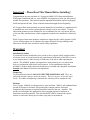
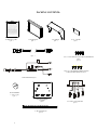
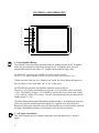
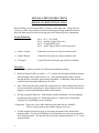
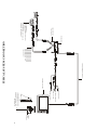
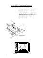
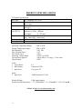
R
AOM681
6.8” FLAT PANEL COLOR OBSERVATION
MONITOR OWNER’S MANUAL
AOM681 Features:
? 6.8” High Performance Color LCD
? Water Resistant Design
? Built-in Audio Speaker with Volume Control
and 12V Trigger
? 2 Camera (A/V) Input with A/B Select Control
? Backlit Controls and Day/Night Picture Modes
for Nighttime Use
? Auto/Manual Power On
? Sun Visor Included
Visit us at http://www.asaelectronics.com
UDIOVOX
PECIALIZED
1
PPLICATIONS, L.L.C.
Important! – Please Read This Manual Before Installing!
Congratulations on your purchase of a Voyager AOM681 LCD Observation Monitor.
With proper installation and use, your AOM681 is designed to provide you with years of
trouble-free operation. This manual contains important information required to properly
install and operate the unit. Please read this manual thoroughly before beginning.
All Voyager Observation products are strictly intended to be installed as a supplement aid
to standard rear-view mirror systems that may already exist in your vehicle. Voyager
observation products are not intended for use as substitutes for rear-view mirror devices,
or for any other standard motor vehicle equipment required to be installed on vehicles by
law.
While Voyager observation products contribute to improving the vehicle operator’s field
of view, these products are no substitute for proper defensive driving techniques and
observance of traffic laws and motor vehicle safety regulations.
Warnings!
Installation Location
It is unlawful in most jurisdictions for a person to drive a motor vehicle equipped with a
television viewer or screen located at any point forward of the back of the driver’s seat or
in any location that is visible, directly or indirectly, to the driver while operating the
vehicle. The AOM681 product is designed to be used primarily as a rear observation
device in conjunction with closed circuit cameras. In any installations where the
AOM681 is used to display television broadcasts or recorded video playback, installation
location must adhere to local laws and regulations.
Tampering
To prevent electrical shock, DO NOT OPEN THE MONITOR CASE. There are
potentially harmful voltages inside the monitor. There are no user serviceable parts
inside. If evidence of tampering is detected, the warranty will be considered void.
Moisture
Your Voyager AOM681 was designed to be water-resistant. While it will withstand short
periods of exposure to moisture, this product does contain sensitive electronic
components and exposure to moisture should be limited by the user / installer. This
product is not designed for applications where constant exposure to moisture or
immersion can be encountered. This unit should NEVER be cleaned with a power
washer or used where direct power washer spray may be encountered.
2
PACKING CONTENTS:
90 DAY/ 12 MONTH LIMITED WARRANTY
Audiovox Specialized Aplications, LLC (the company) warrants to the original retail purchaser of
this product that should this product or any part thereof, under normal use and conditions, be
proven defective in material or workmanship within 90 days from the date of purchase, such
defect(s) will be repaired or replaced (at the company's option) without charge for parts and labor
repair. After the initial 90 day period and for a period of 12 months from the date of original
purchase, the company will supply at no charge a replacement for any defective part(s) but will
charge for the labor to repair the product.
To obtain repair or replacement within the terms of this Warranty, ASA must be called and a return
authorization must be given to reference the product when returned. The product is to be delivered
with proof of waranty coverage (e.g. dated bill of sale), specification of the defect(s), transportation
prepaid, and Return Authorization Number clearly written on the outside of the package. The
product must be returned to ASA for repair unless specified otherwise by ASA.
This warranty does not cover the elimination of externally generated static or noise, to the correction
of antenna problems, to costs incurred for removal or reinstallation of the product, or damage to any
tapes, speakers, accessories, or electrical systems.
This warranty does not apply to any product or part thereof which in the opinion of the company has
been damaged through alteration, improper installation, mishandling, misuse, neglect or accident.
THE EXTENT OF THE COMPANY'S LIABILITY UNDER THIS WARRANTY IS LIMITED TO THE
REPAIR OR REPLACEMENT PROVIDED ABOVE AND, IN NO EVENT SHALL THE COMPANY'S
LIABILITY EXCEED THE PURCHASE PRICE PAID BY THE PURCHASER FOR THE PRODUCT.
This warranty is in lieu of all other express warranties or liabilities, ANY IMPLIED WARRANTIES,
INCLUDING ANY IMPLIED WARRANTY OF MERCHANTABILITY, SHALL BE LIMITED TO THE
DURATION OF THIS WARRANTY. ANY ACTION OR ANY BREACH OF ANY WARRANTY
HEREUNDER INCLUDING ANY IMPLIED WARRANTY OF MERCHANTABILITY MUST BE
BROUGHT WITHIN A PERIOD OF 30 DAYS FROM THE DATE OF PURCHASE. IN NO CASE
SHALL THE COMPANY BE LIABLE FOR ANY CONSEQUENTIAL OR INCIDENTAL DAMAGES
OR BREACH OF THIS OR ANY OTHER WARRANTY, EXPRESS OR IMPLIED, WHATSOEVER.
NO person or representative is authorized to assume for the Company any other than expressed
herein connection of the sale of this product. Some states do not allow limitations on how long an
implied warranty lasts or the exclusion of incidental or consequential damages so the above
limitations or exclusions may not apply to you. This gives you specific legal rights and you may also
have other rights which vary from state to state.
Audiovox Specialized Applications, LLC
WARRANTY CARD
QTY. 1
LCD MONITOR
QTY. 1
SUN SHIELD
QTY. 1
4” X 2” VELCRO
QTY. 1
5’INTERMEDIATE HARNESS
QTY. 1
GND
TRIGGER (+12V)
AUDIO
ACC(+12V)
TRIGGER (+12V)
STANDBY
#8 X ¾” SELF DRILL BLACK SCREWS (HARDWARE
BAG)
QTY.4
#10 X 5/16” PHP THREAD FORMING BLACK
SCREW (HARDWARE BAG) QTY. 4
POWER HARNESS QTY. 1
LCD
POWER PANEL
A/V 1
A/V 1
5
2
1
SPLIT GROMMET
1” O.D. 3/16 I.D.
QTY. 1
STOP
DISTANCE MARKER
STICKER
QTY.1
4” BLACK WIRE TIE
QTY. 4
3
A/V INPUT JUNCTION BOX
QTY.1
CONTROLS AND OPERATION
1
2
3
4
5
5
1. Power/Stand-By Button
The AOM681 has two possible operation modes for turning the unit on/off. In manual
mode, the power button is used to turn the unit on/off. In stand-by mode, the unit
automatically turns on only when 12V is applied to the stand-by trigger wire.
For MANUAL operation, the AOM681 should be wired as follows:
The ACC (+12V) lead (red) should be wired to the ACC feed of the vehicle (switched +12V).
*Please note that if the unit is in “Stand-by On” mode, the Power Button will appear to
have no effect (it will switch from “on” to “on” in this case).
For STAND-BY operation, the AOM681 should be wired as follows:
The ACC (+12V) lead (red) should be wired to the ACC feed of the vehicle (switched
+12V). The Stand-by Trigger (+12V) should be wired to the reverse feed of the vehicle
(+12V when the vehicle is in reverse). The unit will automatically turn on whenever the
standby trigger is +12V.
The power button features dual-illumination (bright and dim). In installations where the
unit is not wired for Stand-by operation and power is applied to the unit, the Power
Button will dimly glow when the unit is off, allowing the user to easily find the control in
low light. Illumination switches to full intensity when the unit is turned on.
2. A/B Input Select Button
This control toggles the active display image back and forth between AV1 and AV2
inputs.
4
3. Day/Night Mode Button This control toggles the unit between “Day” and “Night”
LCD illumination modes. In the “Day” mode, the LCD backlight intensity is at
maximum. In “Night” mode, the LCD backlight is dimmed to a preset level that is more
suitable for low light operation.
4. Picture Adjustment Menu Button
This control accesses an On-Screen-Display (OSD) menu for four LCD picture
adjustments (Brightness, Contrast, Color, and Tint). The first depress of the button
accesses the “Brightness” adjustment. The Volume +/- controls adjust the level, which is
indicated by the bar graph at the bottom of the screen. Each consecutive depress of the
Picture button accesses the adjustment screen for each picture adjustment. If no buttons
are pressed within 6 seconds or controls other than the Picture and Volume buttons are
pressed, the unit will exit the Picture Adjustment mode.
5. Volume +/- Buttons
This 2-button set of controls adjusts the output volume of the built-in audio speaker when
the audio function is enabled *(see typical system connection diagram). The “+” button
increases output volume. The “-“ button decreases output volume. Volume level is
indicated by the OSD bar graph at the bottom of the screen.
These buttons also serve as adjustment controls while in the Picture Adjustment Menu
mode (see above section for details).
*Note: The AOM681 requires +12V to be applied to the “Audio Enable” trigger input in
order to activate the built-in speaker. If no audio output is heard from the speaker
regardless of the volume level adjustment, check this connection.
5
INSTALLATION INSTRUCTIONS
BEFORE YOU BEGIN INSTALLATION:
Before drilling, be sure that no cable or wiring is on the other side. Clamp all wires
securely to reduce the possibility of them being damaged during installation and use.
Keep all cables away from hot or moving parts, and electrically noisy components.
Wiring Definitions:
? Power connection:
Pin 1
Pin 2
Pin 3
Pin 4
ACC +12V (Red)
Standby Trigger (Blue wire)
Ground (Black wire)
Audio Trigger (Blue w/white stripe wire)
? Camera A input:
Connection for camera or camera extension cable
? Camera B input:
Connection for camera or camera extension cable
? LCD panel:
9-pin DIN cable connection: junction box to monitor.
Procedure:
1. Choose the monitor, junction box, and camera mounting locations.
2. Install all required cables in vehicle. A ¾” (19mm) hole should be drilled for passing
cables through vehicle walls, barriers, etc. After the intermediate cable is passed
through the hole, install the split grommet (included). If additional cable protection is
required install convoluted tubing over the cable.
3. After cable/wiring has been routed and components are in place, temporarily make all
system connections and perform a system function check. If system does not operate
properly, see the troubleshooting section of this manual.
4. If using an optional PanaVise? stalk mount (available separately), use the mounting
template provided on page 10. Install the PanaVise? mount to the LCD monitor
using the #10 self-drilling screws (included).
**Important: Do not use screws other than those provided with the AOM681.
Void of warranty and serious product damage will occur.
5. Use the template provided on page 10 for proper placement of the junction box
mounting holes. Use the #8 self-drilling screws (included) to secure the junction box
in the desired location. The junction box can also be mounted using the 2”x 4” velcro
strip (included).
6
6. There are 2 options for connecting the LCD monitor to the junction box. If the
application is such that the monitor is in close proximity to the junction box, the
AOM681 monitor can be connected directly to the junction box. If the junction box
is mounted further from the monitor, use the 5’intermediate cable included with the
AOM681 to connect the monitor to the junction box. If more cable length is needed,
additional 5’lengths of the intermediate cable can be purchased. (See the accessory
list at the back of this manual for part number details.)
7. Connect the 4-pin power harness to vehicle. (See system connection illustration page
8)
8. Plug camera extension cable (available separately P/N CEC25) into AV1 or AV2
input connector on the junction box. Plug observation camera into camera extension
cable.
9. Make sure all cables are routed away from hot or moving parts, and away from sharp
edges. Secure cables with wire ties.
10. For rear observation applications, range marker stickers have been included with this
product. These markers are designed to adhere to your LCD monitor and provide a
reference for gauging distance. See page 9 for illustration showing proper use and
installation of the range markers
7
#10 X 5/16”
TYPE B
SCREWS
B
–
+
A
AOM681 LCD MONITOR
(BLACK) CHASSIS GROUND
(BLUE/WHITE) AUDIO TRIGGER
(RED) +12V SWITCHED
(BLUE) +12V STANDBY TRIGGER
ACCESSORY ITEM
MULTI-AXIS BASES (2 AVAILABLE)
72704 - 4”2-AXIS BASE MOUNT
72706 - 6”3-AXIS BASE MOUNT
ACC (+1 2V)
8510681 5’INTERMEDIATE CABLE
ACCESSORY ITEMS
CEC5 - 5 FT. CAMERA CABLE
CEC15 - 15 FT. CAMERA CABLE
CEC18 - 18 FT. CAMERA CABLE
CEC25 - 25 FT. CAMERA CABLE
CEC50 - 50 FT. CAMERA CABLE
CEC75 - 75 FT. CAMERA CABLE
P OW ER
L CD
PANE L
A/V 1
A/V 2
JUNCTION BOX
#8 X 3/4”SELF
DRILLING SCREWS
ACCESSORY ITEM (2 AVAILABLE)
AOC100B - COLOR CAMERA SWITCHABLE
STD/MIRROR IMAGE
VCC130 - COLOR CAMERA WITH LOW-LIGHT
ENHANCEMENT LED’
s
TYPICAL SYSTEM CONNECTION
TR IGGE R (+1 2V)
STA NDBY
GND
8
T RIGG ER (+ 12V)
AUDIO
REAR OBSERVATION INSTALLATION
DISTANCE MARKER USE/INSTALLATION
-PLACE INDICATOR MARKERS (CONE, BOX ANY
REFERENCE OBJECT HANDY) BEHIND VEHICLE
AS IN FIGURE A.
-PLACE RANGE MARKER DECALS ON SCREEN OF
MONITOR OVER IMAGE OF INDICATOR
MARKERS ON GROUND BEHIND VEHICLE, AS
VIEWED ON THE MONITOR SCREEN.
-THIS GIVES YOU A VISUAL REFERENCE OF
ACTUAL DISTANCE BEHIND VEHICLE, AS
OBJECTS ARE VIEWED.
INDICATOR
MARKERS
1 FT
2 FT
5 FT
WIDTH OF VEHICLE
FIGURE A
5
2
1
STOP
FIGURE B
9
JUNCTION BOX MOUNTING TEMPLATE
SIDE
PANAVISE? MOUNT TEMPLATE
(OPTIONAL ACCESSORY – SEE PAGE 8)
10
TROUBLESHOOTING
SYMPTOM
CAUSE
SOLUTION
No power
No +12V accessory, No
ground, mis-wired/reversed
Replace circuit fuse, monitor has protection
device built-in/reset, check ground connection,
verify power is being supplied
Video/No audio
Blue/white audio trigger wire
not powered, Volume adjust
down
Monitor does not
Blue standby wire not
activate in reverse
powered
Connect to +12V ACC or reverse light circuit,
turn volume adjustment up
Negative/dark
video image
No video/no audio
Low voltage, Brightness
adjustment down
Camera connection
Check voltage power and ground connections,
turn brightness adjustment up
Check camera input selection, connection to
camera and junction box, correct camera
connection/plugged incorrectly
Vehicle battery
drained
+12V ACC (red wire)
connected to vehicle battery
Provide +12V ACC (red wire) power from
switched circuit
Connect to reverse circuit +12V
ACCESSORY LIST
AOC100B – COLOR CAMERA-SWITCHABLE STD/MIRROR IMAGE
VCC130 - COLOR CAMERA W/LOW LIGHT ENHANCEMENT LED’s-MIRROR
IMAGE ONLY
CEC2 – 2 FOOT CAMERA EXTENSION CABLE
CEC15 – 15 FOOT CAMERA EXTENSION CABLE
CEC18 – 18 FOOT CAMERA EXTENSION CABLE
CEC25 – 25 FOOT CAMERA EXTENSION CABLE
CEC50 – 50 FOOT CAMERA EXTENSION CABLE
CEC75 – 75 FOOT CAMERA EXTENSION CABLE
8510681 – 5 FOOT INTERMEDIATE HARNESS
CSW4000 – MANUAL 4 CAMERA SWITCHER
CSW450A – AUTOMATIC 4 CAMERA SWITCHER
FDK681N - FLIP DOWN KIT, AOM681 NEUTRAL
FKD681G – FLIP DOWN KIT, AOM681 GRAY
FDK681PL – FLIP DOWN KIT, AOM681 PEARL
72704 – CELLULAR MOUNT 4” WITH THUMBSCREW
72706 – CELLULAR MOUNT 6” WITH THUMBSCREW
11
PRODUCT SPECIFICATIONS
LCD panel specifications:
Size/Type
6.8” (diagonal) /TFT LCD
Brightness
250 nit (min)
300 nit (typ.)
Contrast Ratio
60 (min)
150 (typ.)
View Angles
Top (12 o’clock):
25?(min)
(@ CR? 10)
Bottom (6 o’clock): 40?(min)
Horizontal:
? 55?(min)
Response Time Rise: 25ms (typ.) ; 50ms (max)
Fall: 30ms (typ.) ; 60ms (max)
Back light Type CCFL
Back light Life
30k hrs (min) ; 40k hrs (typ.)
Operation Temperature Range:
Storage Temperature Range:
Max Humidity:
Max Vibration Force:
Max Shock Force:
Operating Voltage Range:
Current Draw (typical):
Signal System:
-20?C to 65?C
-40?C to 80?C
100? RH
2.5G
100G
10VDC to 16VDC
50mA (Idle); 1.15A (typ) ; 1.25A (max)
NTSC
Video:
? Aspect Ratio:
? Input format:
? Input level:
4:3
Composite NTSC
1Vp-p into 75?
Audio
? Input level:
-10dBV nominal (317mV)
Product Weight:
2.8lbs (approximate)
Product Overall Dimensions: 7 ¾” (197mm)W x 5 ¼” (134mm)H x 1 3/16” (29.5mm)D
Visit us at http://www.asaelectronics.com
12