1
CMP3-L Pyranometer
Revision: 2/09
C o p y r i g h t © 2 0 0 6 - 2 0 0 9
C a m p b e l l S c i e n t i f i c , I n c .
Warranty and Assistance
The CMP3-L PYRANOMETER is warranted by CAMPBELL SCIENTIFIC,
INC. to be free from defects in materials and workmanship under normal use
and service for twelve (12) months from date of shipment unless specified
otherwise. Batteries have no warranty. CAMPBELL SCIENTIFIC, INC.'s
obligation under this warranty is limited to repairing or replacing (at
CAMPBELL SCIENTIFIC, INC.'s option) defective products. The customer
shall assume all costs of removing, reinstalling, and shipping defective
products to CAMPBELL SCIENTIFIC, INC. CAMPBELL SCIENTIFIC,
INC. will return such products by surface carrier prepaid. This warranty shall
not apply to any CAMPBELL SCIENTIFIC, INC. products which have been
subjected to modification, misuse, neglect, accidents of nature, or shipping
damage. This warranty is in lieu of all other warranties, expressed or implied,
including warranties of merchantability or fitness for a particular purpose.
CAMPBELL SCIENTIFIC, INC. is not liable for special, indirect, incidental,
or consequential damages.
Products may not be returned without prior authorization. The following
contact information is for US and International customers residing in countries
served by Campbell Scientific, Inc. directly. Affiliate companies handle
repairs for customers within their territories. Please visit
www.campbellsci.com to determine which Campbell Scientific company
serves your country. To obtain a Returned Materials Authorization (RMA),
contact CAMPBELL SCIENTIFIC, INC., phone (435) 753-2342. After an
applications engineer determines the nature of the problem, an RMA number
will be issued. Please write this number clearly on the outside of the shipping
container. CAMPBELL SCIENTIFIC's shipping address is:
CAMPBELL SCIENTIFIC, INC.
RMA#_____
815 West 1800 North
Logan, Utah 84321-1784
CAMPBELL SCIENTIFIC, INC. does not accept collect calls.
CMP3-L Pyranometer Table of Contents
PDF viewers note: These page numbers refer to the printed version of this document. Use
the Adobe Acrobat® bookmarks tab for links to specific sections.
1. General Description.....................................................1
2. Specifications ..............................................................1
3. Installation....................................................................2
4. Wiring............................................................................4
5. Example Programs ......................................................5
5.1
5.2
5.3
5.4
Input Range...............................................................................................5
Multiplier ..................................................................................................6
Offset ........................................................................................................6
Example Programs....................................................................................7
5.4.1 CR1000 Example Program .............................................................7
5.4.2 CR10X Example Program ..............................................................8
5.5 Output Format Considerations..................................................................9
6. Maintenance ...............................................................10
7. Troubleshooting ........................................................10
Figures
3-1. CMP3-L Pyranometer Attached to CM225 Solar Sensor Mounting Stand3
4-1. CMP3-L Schematic .................................................................................4
Tables
4-1.
4-2.
5-1.
5-2.
Differential Connections to Campbell Scientific Dataloggers ................4
Single-Ended Connections to Campbell Scientific Dataloggers .............5
Multipliers Required for Average Flux Density and Total Fluxes ..........6
Wiring for Example Programs ................................................................7
i
CMP3-L Pyranometer
1. General Description
This manual provides information for interfacing the CMP3-L Pyranometer to
various models of Campbell Scientific dataloggers. The CMP3-L is
manufactured by Kipp & Zonen and then cabled by Campbell Scientific.
Cable length is user specified.
The CMP3-L is shipped with an instruction manual provided by Kipp & Zonen
that contains information concerning the CMP3-L’s construction, spectral
sensitivity, cosine response, and a simple sensor check out procedure.
Included with the sensor and manual is a calibration certificate with the sensor
calibration constant and serial number. Cross check this serial number against
the serial number on your CMP3-L to ensure that the given calibration constant
corresponds to your sensor.
The CMP3-L pyranometer is designed for continuous outdoor use. Due to its
flat spectral sensitivity from 300 to 3000 nm, it can be used in natural sunlight,
under plant canopies, in green houses or buildings, and inverted to measure
reflected solar radiation. Two CMP3-Ls can be used in combination to
measure albedo. The CMP3-L can also be used to measure most types of
artificial light (Xenon lamps, Halogen lamps, etc.).
The CMP3-L pyranometer consists of a thermopile sensor, housing, dome, and
cable. The thermopile is coated with a black absorbent coating. The paint
absorbs the radiation and converts it to heat. The resultant temperature
difference is converted to a voltage by the copper-constantan thermopile. The
thermopile is encapsulated in the housing in such a way that it has a field of
view of 180 degrees and the angular characteristics needed to fulfill the cosine
response requirements.
2. Specifications
The CMP3-L is an ISO Second Class pyranometer. While the worst case
accuracy for daily sums given by Kipp & Zonen is +10%, the typical accuracy
is +5%.
ISO SPECIFICATIONS:
Response Time 95%:
18 seconds
Zero offset due to 200 W/m2 thermal
radiation:
< 15 W m-2
Zero offset due to temperature change
of 5ºK / hr:
< +4 W m-2
Non stability (% change/year):
< + 1%
Non linearity (0 to 1000 W/m2):
< + 2.5%
Directional error (at 80º with
1000 W/m2 beam):
< + 20 W m-2
1
CMP3-L Pyranometer
Temperature Dependence of
sensitivity:
+ 5% (-10º to + 40ºC)
Tilt response (+80º) (at 1000 W/m2):
< + 2%
OTHER SPECIFICATIONS
Expected accuracy for daily sums:
+ 10%
Spectral range (50% points, nm):
310 to 2800 nm
Sensitivity:
5 to 20 μV W-1 m2
Typical signal output for atmospheric
applications:
0 to 15 mV
Impedance:
30 to 100 Ω
Operating Temperature:
-40º to +80ºC
Max. irradiance:
2000 Wm-2
Detector:
Copper-constantan multi junction
thermopile
Level accuracy:
1 degree
DIMENSIONS / SHIPPING DIMENSIONS
CMP3-L:
3 in dia x 4 in / 8x12x4 in
WEIGHT/SHIPPING WEIGHT
CMP3-L:
1.2 lbs / 1.8 lbs
3. Installation
The CMP3-L is usually installed horizontally, but can also be installed at any
angle including an inverted position. In all cases it will measure the flux that is
incident on the surface that is parallel to the sensor surface.
Site the CMP3-L to allow easy access for maintenance while ideally avoiding
any obstructions above the plane of the sensing element. It is important to
mount the CMP3-L such that a shadow will not be cast on it at any time.
If this is not possible, try to choose a site where any obstruction over the
azimuth range between earliest sunrise and latest sunset has an elevation not
exceeding 5°. Diffuse solar radiation is less influenced by obstructions near
the horizon. For instance, an obstruction with an elevation of 5° over the
whole azimuth range of 360° decreases the downward diffuse solar radiation
by only 0.8%.
The sensor should be mounted with the cable pointing towards the nearest
magnetic pole, e.g., in the Northern Hemisphere point the cable toward the
North Pole.
2
CMP3-L Pyranometer
Tools required for installation on a tripod or tower:
Small and medium Phillips screwdrivers
5/16”, 1/2” open end wrenches
5/32” Allen wrench
Tape measure
UV-resistant wire ties
Side-cut pliers
Compass
Step ladder
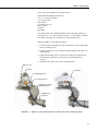
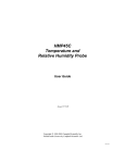
The CM225 Solar Sensor Mounting Stand is used to attach the CMP3-L to a
vertical pipe (1.0 – 2.1” OD) as shown in Figure 3-1. The CMP3-L includes a
base with two levelling screws, bubble level, and mounting screws.
Attach the CMP3-L to the CM225 as follows:
1. Loosely mount the pyranometer on the mounting arm. Do not fully tighten
the two mounting screws.
2. Turn the levelling screws as required to bring the bubble of the spirit level
within the ring.
3. Tighten the mounting screws to secure the assembly in its final position.
Check that the pyranometer is still correctly levelled and adjust as
necessary.
4. Attach the white plastic sun screen to the pyranometer.
Bubble Level
CMP3-L
Sun Shield
(2) Mounting Screws
(3) Leveling Screws
CM225 Solar Sensor
Mounting Stand
CM200 Series
Crossarm
FIGURE 3-1. CMP3-L Pyranometer Attached to CM225 Solar Sensor Mounting Stand
3
CMP3-L Pyranometer
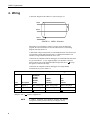
4. Wiring
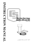
A schematic diagram of the CMP3-L is shown in Figure 4-1.
White
Red
Blue
Black
Black
Shield
FIGURE 4-1. CMP3-L Schematic
When Short Cut for Windows software is used to create the datalogger
program, the sensor should be wired to the channels shown in the wiring
diagram created by Short Cut.
A differential voltage measurement is recommended because it has better noise
rejection than a single-ended measurement. If a differential channel is not
available, a single-ended measurement can be used.
Connections to Campbell Scientific dataloggers for a Differential measurement
are given in Table 4-1. A user supplied jumper wire should be connected
between the low side of the differential input and ground (AG or ) to keep
the signal in common mode range.
Connections to Campbell Scientific dataloggers for a Single-Ended
measurement are given in Table 4-2.
TABLE 4-1. Differential Connections to Campbell Scientific Dataloggers
Color
Description
CR9000(X)
CR5000
CR3000
CR1000
CR800
White
Signal (+)
DIFF Analog High
DIFF Analog High
DIFF Analog High
Black
Signal (-)
*DIFF Analog Low
*DIFF Analog Low
*DIFF Analog Low
Shield
Shield
* Jumper to AG or
NOTE
4
CR510
CR500
CR10(X)
21X
CR7
CR23X
G
with user supplied wire.
A CMP3-L purchased from Campbell Scientific has different
wiring than a CMP3 purchased directly from Kipp & Zonen.
CMP3-L Pyranometer
TABLE 4-2. Single-Ended Connections to Campbell Scientific Dataloggers
Color
Description
CR9000(X)
CR5000
CR3000
CR1000
CR800
White
Signal (+)
Single-Ended Analog
Black
Signal (-)
AG
Shield
Shield
G
CR510
CR500
CR10(X)
21X
CR7
CR23X
Single-Ended Analog
Single-Ended Analog
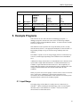
5. Example Programs
This section is for users who write their own datalogger programs. A
datalogger program to measure this sensor can be created using Campbell
Scientific’s Short Cut Program Builder software. You do not need to read this
section to use Short Cut.
Solar radiation can be reported as an average flux density (W m-2) or daily
total flux density (MJ m-2). The appropriate multipliers are listed in Table 5-1.
Programming examples are given for both average and daily total solar
radiation.
The CMP3-L outputs a low level voltage ranging from 0 to a maximum of up
to 20 mV, in natural light, depending on the calibration factor and radiation
level.
A differential voltage measurement is recommended because it has better noise
rejection than a single-ended measurement. If a differential channel is not
available, a single-ended measurement can be used. The acceptability of a
single-ended measurement can be determined by simply comparing the results
of single-ended and differential measurements made under the same
conditions.
Nearby AC power lines, electric pumps, or motors can be a source of electrical
noise. If the sensor or datalogger is located in an electrically noisy
environment, the measurement should be made with the 60 or 50 Hz rejection
integration option as shown in the example programs.
5.1 Input Range
The output voltage of the CMP3-L is usually between 5 and 20 mV per
1000 Wm-2. When estimating the maximum likely value of sensor output a
maximum value of solar radiation of 1100 Wm-2 can be used for field
measurements on a horizontal surface.
5
CMP3-L Pyranometer
Select the input range as follows:
1.
Estimate the maximum expected input voltage by multiplying the
maximum expected irradiance (in Wm-2) by the calibration factor (in
µV/Wm-2). Divide the answer by 1000 to give the maximum in millivolt
units.
2.
Select the smallest input range which is greater than the maximum
expected input voltage. Normally the 50 mV range for the CR23X,
CR5000, CR9000 and CR7, and the 25 mV or 250 mV range for the
CR510, CR10X and CR1000 will be suitable. The exact range will
depend on the sensitivity of your individual sensor and the maximum
expected reading. With some dataloggers an autorange option can be used
if measurement time is not critical.
The parameter code for the input range also specifies the measurement
integration time. The slow or 60 Hz rejection integration gives a more noisefree reading. A fast integration takes less power and allows for faster
throughput.
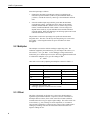
5.2 Multiplier
The multiplier converts the millivolt reading to engineering units. The
calibration supplied by the manufacturer gives the output of the sensor (c) as
microvolts (V x 10-6 ) per Wm-2. As the datalogger voltage measurement
instructions give a default output in mV, the following equation should be used
to calculate the multiplier (m) to give the readings in Wm-2:
m = 1000/c
Other units can be used by adjusting the multiplier as shown in Table 5-1.
TABLE 5-1. Multipliers Required for Flux Density and Total Fluxes
Units
Multipliers
Output Processing
m
Average
m*t*0.000001
Total
kJ m-2
m*t*0.001
Total
cal cm-2
m*t*0.0239*0.001
Total
cal cm-2 min-1
m*1.434*0.001
Average
W
m-2
MJ
m-2
m = calibration factor in Wm-2/mV
t = datalogger program execution interval in seconds
5.3 Offset
The offset will normally be fixed at zero as the sensor should output no
significant signal in dark conditions. In practice, because of the nature of
thermopile detector sensors, there will be some offset in dark conditions;
sometimes this offset can give negative light readings. This offset varies with
several factors, e.g. rate of change of sensor temperature, so it cannot be
removed with a fixed offset. Some users may wish to remove small negative
readings by including code after the measurement instructions that sets
negative readings to zero.
6
CMP3-L Pyranometer
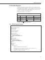
5.4 Example Programs
The following programs measure the CMP3-L every 10 seconds and convert
the mV output to Wm-2 and MJm-2. A sensor calibration of 15.02 µV per Wm2
is used for the example programs. Both programs output an hourly average
flux (Wm-2), and a daily total flux density (MJ m-2).
Wiring for the examples is given in Table 5-2.
TABLE 5-2. Wiring for Example Programs
Color
Description
CR1000
CR10X
White
Signal (+)
DIFF Analog High
DIFF Analog High
Black
Signal (-)
*DIFF Analog Low
*DIFF Analog Low
Shield
Shield
* Jumper to AG or
G
with user supplied wire.
5.4.1 CR1000 Example Program
'CR1000
'Declare Variables and Units
Public Solar_Wm2
Public Solar_MJ
Units Solar_Wm2=W/m²
Units Solar_MJ=MJ/m²
'Hourly Data Table
DataTable(Table1,True,-1)
DataInterval(0,60,Min,10)
Average(1,Solar_Wm2,FP2,False)
EndTable
'Daily Data Table
DataTable(Table2,True,-1)
DataInterval(0,1440,Min,10)
Totalize(1,Solar_MJ,IEEE4,False)
EndTable
'Main Program
BeginProg
Scan(10,Sec,1,0)
'CMP3-L Pyranometer measurement in Wm-2:
'The Multiplier (m) for this example is based upon a sensor calibration (c) of
'15.02 µV/Wm-2, and will be different for each sensor.
'Multiplier (m) = 1000/c = 66.577896.
7
CMP3-L Pyranometer
VoltDiff(Solar_Wm2,1,mV25,1,True,0,_60Hz,66.577896,0) ‘use the 50 mV range for the
CR3000, CR5000 and CR9000
'Set negative readings to zero:
If Solar_Wm2<0 Then Solar_Wm2=0
'Calculate units in MJ, where MJ = m * t * 0.000001. m = Solar_Wm2 from above, and
't = 10 (scan interval)
Solar_MJ=Solar_Wm2*0.00001
'Call Data Tables and Store Data
CallTable(Table1)
CallTable(Table2)
NextScan
EndProg
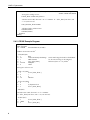
5.4.2 CR10X Example Program
;{CR10X}
*Table 1 Program
01: 10.0000
Execution Interval (seconds)
; CMP3-L measurement in Wm-2
1: Volt (Diff) (P2)
1: 1
2: 23
3: 1
4: 3
5: 66.5778
6: 0
Reps
25 mV 60 Hz Rejection Range
DIFF Channel
Loc [ Solar_Wm2 ]
Multiplier
Offset
;use the 50 mV range for the CR7, 21X and CR23X
;use the 250 mV range for the CR10X if
calibration factor is > 25 µV/Wm-2
; Set negative values to zero
2: If (X<=>F) (P89)
1: 3
X Loc [ Solar_Wm2 ]
2: 4
<
3: 0
F
4: 30
Then Do
3: Z=F x 10^n (P30)
1: 0
F
2: 0
n, Exponent of 10
3: 3
Z Loc [ Solar_Wm2 ]
4: End (P95)
; Calculate units in MJ, where MJ = m * t * 0.000001.
; m = Solar_Wm2 from above, and t = 10 (scan interval).
5: Z=X*F (P37)
1: 3
2: .00001
3: 4
8
X Loc [ Solar_Wm2 ]
F
Z Loc [ Solar_MJ ]
CMP3-L Pyranometer
6: If time is (P92)
1: 0
Minutes (Seconds --) into a
2: 60
Interval (same units as above)
3: 10
Set Output Flag High (Flag 0)
7: Set Active Storage Area (P80)
1: 1
Final Storage Area 1
2: 101
Array ID
8: Real Time (P77)
1: 1220
Year,Day,Hour/Minute (midnight = 2400)
9: Average (P71)
1: 1
Reps
2: 3
Loc [ Solar_Wm2 ]
10: If time is (P92)
1: 0
Minutes (Seconds --) into a
2: 1440
Interval (same units as above)
3: 10
Set Output Flag High (Flag 0)
11: Set Active Storage Area (P80)
1: 1
Final Storage Area 1
2: 102
Array ID
12: Real Time (P77)
1: 1220
Year,Day,Hour/Minute (midnight = 2400)
13: Resolution (P78)
1: 1
High Resolution
14: Totalize (P72)
1: 1
Reps
2: 4
Loc [ Solar_MJ ]
15: Resolution (P78)
1: 0
Low Resolution
5.5 Output Format Considerations
When using the Campbell Scientific floating point data format to store data,
the largest number the datalogger can store in Final Storage is 6999 in low
resolution mode (FP2) and 99999 in high resolution mode (if available). If the
measurement value is totalized, there is some danger of over-ranging the
output limits, as shown in the following example:
Example
Assume that daily total flux is desired, and that the datalogger scan rate is 1
second. With a multiplier that converts the readings to units of kJ m-2 and an
average irradiance of 0.5kWm-2, the maximum low resolution output limit will
be exceeded in less than four hours.
9
CMP3-L Pyranometer
Solution 1 – Change the multiplier in the instruction to (m*0.0001). This will
totalize MJ m-2 instead of kJ m-2.
Solution 2 – Record the average flux density and later multiply the result by
the number of seconds in the output interval to arrive at total flux.
Solution 3 – Record the total flux using the high resolution format. The
drawback to high resolution is that it requires four bytes of memory per data
point, consuming twice as much memory as low resolution. Instruction 78 is
used to switch to high resolution in the Edlog dataloggers.
Dataloggers that are programmed in CRBasic can be programmed to store data
in IEEE4 format which can represent a wider range of numbers so this is not a
consideration for them.
6. Maintenance
Inspect and clean the outer dome at regular intervals, e.g. every week or so.
Clean any accumulated dust, etc. off the dome and pyranometer body using a
soft cloth dampened with water or alcohol. Check that there is no
condensation within the dome.
It is also important to check the data returned from the sensor as it will show
the first indication of a fault. When doing this you should be aware of several
expected phenomena that can cause strange measurements. In particular on
clear, windless nights the outer dome temperature of horizontally placed
pyranometers can fall as low as the dew point temperature of the air, due to
infra-red radiation exchange with the cold sky. (The effective sky temperature
can be 30°C lower than the ground temperature, which results in an infra-red
emission of -150 Wm-2). If this happens, dew, glazed frost or hoar frost can be
precipitated on the top of the outer dome and can stay there for several hours in
the morning. An ice cap on the dome is a strong diffuser and can increase the
pyranometer signal by up to 50% in the first hours after sunrise.
The calibration of the CMP3-L may drift with time and exposure to radiation.
Recalibration every two years is recommended. The sensor should be returned
to Campbell Scientific, the manufacturer, or a calibration lab with facilities to
calibrate radiation sensors.
7. Troubleshooting
Symptom: -9999 or radiation values around 0
10
1.
Check that the sensor is wired to the Differential channel specified by the
measurement instruction.
2.
Verify that the Range code is correct for the datalogger type.
3.
Measure the impedance across the red and blue sensor wires. This should
be around 100 ohms plus the cable resistance (typically 0.1 ohm/m). If
the resistance is very low there may be a short circuit (check the wiring).
Resistances somewhat lower than expected could be due to water ingress
CMP3-L Pyranometer
into the sensor or enclosure connectors. If the resistance is infinite, there
is a broken connection (check the wiring).
4.
Disconnect the sensor cable and check the voltage output from the sensor.
With the sensor located 8” below a 60 W incandescent light bulb the
voltage should be approximately 2.5 mV. No voltage indicates a problem
with the sensor.
Symptom: sensor signal is unrealistically high or low
1.
Check that the right calibration factor has been properly entered into the
datalogger program. Please note that each sensor has its own individual
calibration factor.
2.
Check the condition of the sensor cable.
Symptom: sensor signal shows unexpected variations
1.
Check for the presence of strong sources of electromagnetic radiation
(radar, radio etc.)
2.
Check the condition and the connection of the sensor shield wire.
3.
Check the condition of the sensor cable.
11
CMP3-L Pyranometer
12
This is a blank page.
Campbell Scientific Companies
Campbell Scientific, Inc. (CSI)
815 West 1800 North
Logan, Utah 84321
UNITED STATES
www.campbellsci.com
[email protected]
Campbell Scientific Africa Pty. Ltd. (CSAf)
PO Box 2450
Somerset West 7129
SOUTH AFRICA
www.csafrica.co.za
[email protected]
Campbell Scientific Australia Pty. Ltd. (CSA)
PO Box 444
Thuringowa Central
QLD 4812 AUSTRALIA
www.campbellsci.com.au
[email protected]
Campbell Scientific do Brazil Ltda. (CSB)
Rua Luisa Crapsi Orsi, 15 Butantã
CEP: 005543-000 São Paulo SP BRAZIL
www.campbellsci.com.br
[email protected]
Campbell Scientific Canada Corp. (CSC)
11564 - 149th Street NW
Edmonton, Alberta T5M 1W7
CANADA
www.campbellsci.ca
[email protected]
Campbell Scientific Ltd. (CSL)
Campbell Park
80 Hathern Road
Shepshed, Loughborough LE12 9GX
UNITED KINGDOM
www.campbellsci.co.uk
[email protected]
Campbell Scientific Ltd. (France)
Miniparc du Verger - Bat. H
1, rue de Terre Neuve - Les Ulis
91967 COURTABOEUF CEDEX
FRANCE
www.campbellsci.fr
[email protected]
Campbell Scientific Spain, S. L.
Psg. Font 14, local 8
08013 Barcelona
SPAIN
www.campbellsci.es
[email protected]
Please visit www.campbellsci.com to obtain contact information for your local US or International representative.